EP3379014A1 - Glasartikel - Google Patents
Glasartikel Download PDFInfo
- Publication number
- EP3379014A1 EP3379014A1 EP16866438.1A EP16866438A EP3379014A1 EP 3379014 A1 EP3379014 A1 EP 3379014A1 EP 16866438 A EP16866438 A EP 16866438A EP 3379014 A1 EP3379014 A1 EP 3379014A1
- Authority
- EP
- European Patent Office
- Prior art keywords
- coverage area
- glass plate
- film thickness
- glass
- functional film
- Prior art date
- Legal status (The legal status is an assumption and is not a legal conclusion. Google has not performed a legal analysis and makes no representation as to the accuracy of the status listed.)
- Granted
Links
Images


Classifications
-
- E—FIXED CONSTRUCTIONS
- E05—LOCKS; KEYS; WINDOW OR DOOR FITTINGS; SAFES
- E05F—DEVICES FOR MOVING WINGS INTO OPEN OR CLOSED POSITION; CHECKS FOR WINGS; WING FITTINGS NOT OTHERWISE PROVIDED FOR, CONCERNED WITH THE FUNCTIONING OF THE WING
- E05F11/00—Man-operated mechanisms for operating wings, including those which also operate the fastening
- E05F11/38—Man-operated mechanisms for operating wings, including those which also operate the fastening for sliding windows, e.g. vehicle windows, to be opened or closed by vertical movement
- E05F11/382—Man-operated mechanisms for operating wings, including those which also operate the fastening for sliding windows, e.g. vehicle windows, to be opened or closed by vertical movement for vehicle windows
- E05F11/385—Fixing of window glass to the carrier of the operating mechanism
-
- B—PERFORMING OPERATIONS; TRANSPORTING
- B60—VEHICLES IN GENERAL
- B60J—WINDOWS, WINDSCREENS, NON-FIXED ROOFS, DOORS, OR SIMILAR DEVICES FOR VEHICLES; REMOVABLE EXTERNAL PROTECTIVE COVERINGS SPECIALLY ADAPTED FOR VEHICLES
- B60J1/00—Windows; Windscreens; Accessories therefor
- B60J1/004—Mounting of windows
- B60J1/006—Mounting of windows characterised by fixation means such as clips, adhesive, etc.
-
- C—CHEMISTRY; METALLURGY
- C03—GLASS; MINERAL OR SLAG WOOL
- C03C—CHEMICAL COMPOSITION OF GLASSES, GLAZES OR VITREOUS ENAMELS; SURFACE TREATMENT OF GLASS; SURFACE TREATMENT OF FIBRES OR FILAMENTS MADE FROM GLASS, MINERALS OR SLAGS; JOINING GLASS TO GLASS OR OTHER MATERIALS
- C03C17/00—Surface treatment of glass, not in the form of fibres or filaments, by coating
- C03C17/006—Surface treatment of glass, not in the form of fibres or filaments, by coating with materials of composite character
- C03C17/008—Surface treatment of glass, not in the form of fibres or filaments, by coating with materials of composite character comprising a mixture of materials covered by two or more of the groups C03C17/02, C03C17/06, C03C17/22 and C03C17/28
- C03C17/009—Mixtures of organic and inorganic materials, e.g. ormosils and ormocers
-
- C—CHEMISTRY; METALLURGY
- C03—GLASS; MINERAL OR SLAG WOOL
- C03C—CHEMICAL COMPOSITION OF GLASSES, GLAZES OR VITREOUS ENAMELS; SURFACE TREATMENT OF GLASS; SURFACE TREATMENT OF FIBRES OR FILAMENTS MADE FROM GLASS, MINERALS OR SLAGS; JOINING GLASS TO GLASS OR OTHER MATERIALS
- C03C17/00—Surface treatment of glass, not in the form of fibres or filaments, by coating
- C03C17/28—Surface treatment of glass, not in the form of fibres or filaments, by coating with organic material
-
- E—FIXED CONSTRUCTIONS
- E05—LOCKS; KEYS; WINDOW OR DOOR FITTINGS; SAFES
- E05F—DEVICES FOR MOVING WINGS INTO OPEN OR CLOSED POSITION; CHECKS FOR WINGS; WING FITTINGS NOT OTHERWISE PROVIDED FOR, CONCERNED WITH THE FUNCTIONING OF THE WING
- E05F11/00—Man-operated mechanisms for operating wings, including those which also operate the fastening
- E05F11/38—Man-operated mechanisms for operating wings, including those which also operate the fastening for sliding windows, e.g. vehicle windows, to be opened or closed by vertical movement
-
- C—CHEMISTRY; METALLURGY
- C03—GLASS; MINERAL OR SLAG WOOL
- C03C—CHEMICAL COMPOSITION OF GLASSES, GLAZES OR VITREOUS ENAMELS; SURFACE TREATMENT OF GLASS; SURFACE TREATMENT OF FIBRES OR FILAMENTS MADE FROM GLASS, MINERALS OR SLAGS; JOINING GLASS TO GLASS OR OTHER MATERIALS
- C03C2217/00—Coatings on glass
- C03C2217/40—Coatings comprising at least one inhomogeneous layer
- C03C2217/43—Coatings comprising at least one inhomogeneous layer consisting of a dispersed phase in a continuous phase
- C03C2217/44—Coatings comprising at least one inhomogeneous layer consisting of a dispersed phase in a continuous phase characterized by the composition of the continuous phase
- C03C2217/445—Organic continuous phases
-
- C—CHEMISTRY; METALLURGY
- C03—GLASS; MINERAL OR SLAG WOOL
- C03C—CHEMICAL COMPOSITION OF GLASSES, GLAZES OR VITREOUS ENAMELS; SURFACE TREATMENT OF GLASS; SURFACE TREATMENT OF FIBRES OR FILAMENTS MADE FROM GLASS, MINERALS OR SLAGS; JOINING GLASS TO GLASS OR OTHER MATERIALS
- C03C2217/00—Coatings on glass
- C03C2217/40—Coatings comprising at least one inhomogeneous layer
- C03C2217/43—Coatings comprising at least one inhomogeneous layer consisting of a dispersed phase in a continuous phase
- C03C2217/46—Coatings comprising at least one inhomogeneous layer consisting of a dispersed phase in a continuous phase characterized by the dispersed phase
- C03C2217/47—Coatings comprising at least one inhomogeneous layer consisting of a dispersed phase in a continuous phase characterized by the dispersed phase consisting of a specific material
- C03C2217/475—Inorganic materials
-
- C—CHEMISTRY; METALLURGY
- C03—GLASS; MINERAL OR SLAG WOOL
- C03C—CHEMICAL COMPOSITION OF GLASSES, GLAZES OR VITREOUS ENAMELS; SURFACE TREATMENT OF GLASS; SURFACE TREATMENT OF FIBRES OR FILAMENTS MADE FROM GLASS, MINERALS OR SLAGS; JOINING GLASS TO GLASS OR OTHER MATERIALS
- C03C2217/00—Coatings on glass
- C03C2217/40—Coatings comprising at least one inhomogeneous layer
- C03C2217/43—Coatings comprising at least one inhomogeneous layer consisting of a dispersed phase in a continuous phase
- C03C2217/46—Coatings comprising at least one inhomogeneous layer consisting of a dispersed phase in a continuous phase characterized by the dispersed phase
- C03C2217/48—Coatings comprising at least one inhomogeneous layer consisting of a dispersed phase in a continuous phase characterized by the dispersed phase having a specific function
-
- E—FIXED CONSTRUCTIONS
- E05—LOCKS; KEYS; WINDOW OR DOOR FITTINGS; SAFES
- E05F—DEVICES FOR MOVING WINGS INTO OPEN OR CLOSED POSITION; CHECKS FOR WINGS; WING FITTINGS NOT OTHERWISE PROVIDED FOR, CONCERNED WITH THE FUNCTIONING OF THE WING
- E05F11/00—Man-operated mechanisms for operating wings, including those which also operate the fastening
- E05F11/38—Man-operated mechanisms for operating wings, including those which also operate the fastening for sliding windows, e.g. vehicle windows, to be opened or closed by vertical movement
- E05F11/44—Man-operated mechanisms for operating wings, including those which also operate the fastening for sliding windows, e.g. vehicle windows, to be opened or closed by vertical movement operated by one or more lifting arms
- E05F11/445—Man-operated mechanisms for operating wings, including those which also operate the fastening for sliding windows, e.g. vehicle windows, to be opened or closed by vertical movement operated by one or more lifting arms for vehicle windows
-
- E—FIXED CONSTRUCTIONS
- E05—LOCKS; KEYS; WINDOW OR DOOR FITTINGS; SAFES
- E05F—DEVICES FOR MOVING WINGS INTO OPEN OR CLOSED POSITION; CHECKS FOR WINGS; WING FITTINGS NOT OTHERWISE PROVIDED FOR, CONCERNED WITH THE FUNCTIONING OF THE WING
- E05F11/00—Man-operated mechanisms for operating wings, including those which also operate the fastening
- E05F11/53—Man-operated mechanisms for operating wings, including those which also operate the fastening for sliding windows, e.g. vehicle windows, to be opened or closed by horizontal movement
- E05F11/535—Man-operated mechanisms for operating wings, including those which also operate the fastening for sliding windows, e.g. vehicle windows, to be opened or closed by horizontal movement for vehicle windows
-
- E—FIXED CONSTRUCTIONS
- E05—LOCKS; KEYS; WINDOW OR DOOR FITTINGS; SAFES
- E05Y—INDEXING SCHEME ASSOCIATED WITH SUBCLASSES E05D AND E05F, RELATING TO CONSTRUCTION ELEMENTS, ELECTRIC CONTROL, POWER SUPPLY, POWER SIGNAL OR TRANSMISSION, USER INTERFACES, MOUNTING OR COUPLING, DETAILS, ACCESSORIES, AUXILIARY OPERATIONS NOT OTHERWISE PROVIDED FOR, APPLICATION THEREOF
- E05Y2600/00—Mounting or coupling arrangements for elements provided for in this subclass
- E05Y2600/50—Mounting methods; Positioning
- E05Y2600/52—Toolless
- E05Y2600/526—Gluing or cementing
Definitions
- the present invention relates to a glass article having a glass plate, a functional film provided on one of principal surfaces of the glass plate, and a holder provided in the glass plate.
- a method for providing an automobile window glass with a holder in order to mount the automobile window glass on a lifting and lowering device to lift and lower the automobile window glass for example, see Patent Reference 2.
- a film thickness of the functional film on a lower edge side is larger than a film thickness of the functional film on an upper edge side of a glass plate when the window glass is installed in the vehicle. Accordingly, the film thicknesses of the functional film are different in a height direction of the glass plate, particularly, the film thickness of the functional film on the lower edge side being large, and thus there is a possibility that a failure occurs such as in adhesiveness between the functional film and the glass plate when the glass plate is provided with a holder.
- Patent Reference 2 A method for providing the holder in the automobile window glass is described in Patent Reference 2.
- Patent Reference 2 does not describe a relationship between a shape of the functional film formed on the automobile window glass and the holder, that is, what shape of the functional film makes the functional film hard to be peeled from the automobile window glass when the holder is to be mounted, and such a problem is not considered at all.
- An object of the present invention is to provide a glass article capable of suppressing peeling of a functional film when a holder is mounted on a glass plate provided with a functional film.
- the present invention is a glass article which has: a glass plate having a contour shape having an upper edge and a lower edge; a functional film formed on at least one of principal surfaces of the glass plate; and a holder having a recessed portion into which the lower edge of the glass plate is fitted, wherein the functional film has a first coverage area and a second coverage area, the second coverage area being formed in a manner to cover the principal surface extending from the upper edge toward the lower edge of the glass plate, the first coverage area being formed on a lower side of the second coverage area, along the lower edge, and a maximum film thickness of the first coverage area being smaller than a maximum film thickness of the second coverage area, and the holder is provided on a lower edge side of the glass plate, within the first coverage area of functional film, via an adhesive in the recessed portion
- Fig. 1 is a side view illustrating one of examples of a glass article of the present invention.
- the glass article of the present invention has a glass plate 1, a functional film 6 formed on at least one of principal surfaces of the glass plate, and a holder 2 which supports a lower edge of the glass plate and has a recessed portion into which the lower edge of the glass plate 1 is fitted.
- the functional film is not limited to a film absorbing ultraviolet ray or a film absorbing ultraviolet ray and infrared ray and may be an antifogging film, a water-repellent film, or the like, for example.
- the glass plate 1 has a contour shape having an upper edge A and a lower edge B.
- the glass plate 1 is used as a glass plate for a window of an automobile vehicle, for example, as a glass plate for a window of a front door or a rear door
- the glass plate 1 is a curved or flat glass plate whose schematic shape is almost rectangular.
- the curved glass plate there is usually used a curved glass plate with a concave surface on an indoor side and a convex surface on an outdoor side of the automobile vehicle.
- the functional film is the film absorbing ultraviolet ray or film absorbing the ultraviolet ray and the infrared ray
- the functional film is preferably formed on the concave surface on the indoor side of the automobile vehicle.
- the functional film 6 provided on the glass plate 1 has a first coverage area 4 and a second coverage area 5 from the lower edge toward the upper edge of the glass plate 1, and is provided in a manner that a maximum film thickness of the second coverage area 5 is larger than a maximum film thickness of the first coverage area 4.
- Fig. 2 is a side view illustrating another one of the examples of the glass article of the present invention.
- the functional film may have a form in which a second coverage area gradually increases from a lower edge side toward an upper edge side of a glass plate, or a second coverage area may have almost the same film thickness from an upper edge side toward a lower edge side of a glass plate.
- the second coverage area 5 is preferably formed on a principal surface on an indoor side of the glass plate, and to cover a main area of the principal surface which extends from the upper edge toward the lower edge of the glass plate.
- the main area of the principal surface is an area corresponding to an opening portion of the window in a case of the automobile vehicle.
- the first coverage area is preferably formed on the surface on the indoor side of the glass plate, on a lower side of the second coverage area along the lower edge.
- the glass plate is a window glass mounted openably and closably by being lifted and lowered in a vertical direction in the opening portion of the window of the automobile vehicle
- the main area of the second coverage area is provided to be placed in an opening area of the opening portion and that the main area of the first coverage area is provided to be placed outside the opening area below the opening portion.
- a maximum film thickness of the first coverage area is smaller than a maximum film thickness of the second coverage area.
- a difference between the maximum film thickness and a minimum film thickness in the first coverage area is preferably smaller than a difference between the maximum film thickness and a minimum film thickness in the second coverage area (that is, a film thickness difference in the second coverage area).
- the film thickness of the first coverage area and the film thickness of the second coverage area may be each uniform. Also in such a case, as described above, the maximum film thickness of the first coverage area is smaller than the maximum film thickness of the second coverage area.
- the holder is provided in the first coverage area in which the difference between the maximum film thickness and the minimum film thickness is small (that is, the film thickness is more uniform) and whose film thickness is smaller.
- the holder is provided in a manner not to straddle a boundary region between the first coverage area and the second coverage area, since peeling of the functional film from the glass plate can be suppressed when the holder is mounted as described above.
- Formation of the functional film on a glass plate surface can be attained by applying a coating solution being a liquid composition described later on the glass plate surface and performing a curing processing.
- the glass plate on which the coating solution is applied is held with the coated surface upward, a part of the coating solution in a coated area positioned on the lower edge side of the glass plate and having a certain width from the lower edge side toward the upper edge side is removed by using a blade or the like to obtain a thinner film, and thereafter, the coating solution is cured to form the functional film.
- a width of the first coverage area formed below the second coverage area of the functional film that is, the width of the first coverage area from the lower edge toward the upper edge of the glass plate, is not limited in particular. More preferably, as described above, in a case where the glass plate is the window glass mounted openably and closably by being lifted and lowered in the vertical direction in the opening portion of the window of the automobile vehicle, it is preferable that, when the glass plate is lifted to close the opening portion, the main area of the first coverage area is provided to be positioned on the lower edge side of the window which is zoned below the opening portion (that is, outside the opening area of the opening portion of the window).
- the main area of the first coverage area is an area corresponding to a position at which the holder is mounted, and outside the opening area on the lower side of the opening portion in the glass plate.
- the main area of the first coverage area may straddle the area positioned on the lower edge side of the window which is zoned on the lower area of the opening portion and an area positioned outside the opening area on the lower side of the opening portion, in the glass plate.
- a material of the holder is not limited in particular.
- a resin for example, there can be used one whose major constituent is a polybutylene terephthalate resin, a polyethylene terephthalate resin, or a polyamide resin.
- Fig. 3 is a perspective view illustrating an example of a holder applied to the glass article of the present invention.
- a holder for a vehicle window glass to be mounted on a driving unit which vertically moves the glass article of the present invention in an opening portion of a window or a door for an automobile vehicle.
- a holder 2 has a main body portion 12 having a recessed portion 11 which fits a glass plate (not illustrated) therein to sandwich it, and a leg portion 13 to be mounted on the driving unit which lifts and lowers the glass plate in the vertical direction.
- projecting portions 14 for stemming, to prevent running over of an adhesive infused into the recessed portion are provided on both end sides of the groove-shaped recessed portion 11 of the main body portion 12 in a manner to project toward inside of the recessed portion 11.
- Fig. 4 is a schematic configuration diagram illustrating a window portion of an automobile vehicle having a lifting and lowering device to vertically lift and lower the glass article for the automobile vehicle as an example of the present invention.
- a window glass plate 20 applied as a window glass of a front door or a rear door for an automobile vehicle is vertically lifted and lowered along a window frame 22 around an opening portion of the window by a lifting and lowering device 21, as illustrated in Fig. 4 .
- the lifting and lowering device 21 of the example illustrated in Fig. 4 is an arm type regulator and is basically constitute by two arms 23 and 24, a lifting and lowering rail 25, and a fixed rail 27.
- a broken line C in Fig. 4 schematically illustrates a position of a lower end of the opening portion of the window of the automobile vehicle.
- the two arms 23 and 24 are coupled with each other rotatably around a fulcrum 26 as an axis.
- the lifting and lowering rail 25, extending in a horizontal direction is a rail capable of moving up and down in relation to a vehicle door. Upper ends of the arms 23 and 24 are both mounted on the lifting and lowering rail 25 slidably in the horizontal direction.
- the fixed rail 27, extending in the horizontal direction is a rail fixed to the vehicle door. A lower end of the arm 23 is mounted on the fixed rail 27 slidably in the horizontal direction, and a lower end of the arm 24 is connected to a gear 28 of the regulator.
- the lifting and lowering device is not limited to the arm type regulator and may be a wire type regulator and the like.
- the window glass plate 20 illustrated in Fig. 4 has two holders 2 in a lower edge thereof.
- the holder 2 into a recessed portion of which the lower edge of the glass plate 20 is fitted, is bonded to the window glass plate 20 via an adhesive in the recessed portion of the holder 2.
- a leg portion (corresponding to the leg portion 13 in Fig. 3 ) of the holder 2 is mounted on the lifting and lowering rail 25 of the lifting and lowering device 21.
- the window glass plate 20 is coupled with the lifting and lowering rail 25 via the holder 2. Therefore, the window glass plate 20 is integrally lifted and lowered by up and down of the lifting and lowering rail 25 of the lifting and lowering device 21.
- the holder is installed in the glass plate via the adhesive.
- the adhesive a polyurethane based adhesive or a silicon based adhesive can be cited.
- the polyurethane based adhesive is preferable among the above.
- a proper amount of adhesive is applied to the recessed portion of the holder. Then, a lower portion of the glass plate is pushed into the recessed portion of the holder in a manner that the recessed portion of the holder to which the adhesive has been applied is fitted into the first coverage area of a lower edge area of the glass plate, to thereby install the holder in the glass plate.
- the glass article in which the holder is installed in the glass plate via the adhesive is let to stand as it is or put into a heating furnace or a drying furnace, to thereby cure the adhesive between the holder and the glass plate.
- the adhesive is cured, the holder and the glass plate are bonded via the adhesive, so that the holder and the glass plate are fixed.
- the holder is mounted on the glass plate.
- the holder is preferably mounted in a manner to cover the first coverage area of the functional film formed on one of the principal surfaces of the glass plate, from the lower edge side of the glass plate. It suffices that the holder covers at least a part of the first coverage area of the functional film, and the holder may cover the whole first coverage area depending on a shape of the holder. In other words, the holder is provided within the first coverage area. As described above, it is preferable, in view of film peeling, that the holder does not reach the second coverage area by straddling the boundary area between the first coverage area and the second coverage area.
- the glass article of the present invention preferably further satisfies either one of following (1) and (2). It is more preferable in particular that both (1) and (2) are satisfied in view of attainment of both ultraviolet absorbing ability and abrasion resistance.
- the ultraviolet transmittance Tuv 1 [%] measured based on ISO-9050 (year 1990) is preferably 2.0[%] or less and more preferably 1.5[%] or less
- Tuv 2 [%] after the accelerated weathering test is preferably 3.5[%] or less and more preferably 3.0[%] or less
- the accelerated weathering test being the test in which the portion where Tuv[%] is 1.0[%] in the second coverage area of the glass article is left for 1000 hours in the super xenon weather meter (SX75 by Suga Test Instruments Co., Ltd.) whose condition is set as 150W/m 2 (300 to 400 nm) in irradiance, 83 °C in black panel temperature, and 50 RH% in humidity.
- the glass article has a sufficient ultraviolet absorbing ability in a broad range in the glass surface and exhibits a sufficient weather resistance when the glass article is practically used as an automobile window glass.
- the haze value (H 1 ) in the maximum film thickness portion of the second coverage area is preferably 0.5[%] or less and more preferably 0.3[%] or less before the abrasion test of 1000 rotation to the surface of the functional film of the glass article of the present invention by the CS-10F abrasion wheel in accordance with JIS-R3212 (year 1998) by using the Taber abrasion tester, and the haze value (H 2 ) after the abrasion test is preferably 4.0[%] or less and more preferably 3.0[%] or less.
- the abrasion resistance is high, so that significant visibility deterioration can be prevented.
- a material of the glass plate usable in the present invention is not limited in particular and there can be cited inorganic glass such as soda lime glass (for example, float plate glass, heat absorbing plate glass, ultraviolet absorbing plate glass, heat absorbing and ultraviolet absorbing plate glass, and so on), borosilicate glass, non-alkali glass, and quartz glass, and organic glass such as polycarbonate resin and acrylic resin.
- the inorganic glass is more preferable. It is more preferable that such a glass plate, when used as a window glass for an automobile vehicle, is used as tempered glass having been subjected to tempering or laminated glass having been subjected to laminating.
- the liquid composition used for forming the functional film of the present invention is one capable of forming a coating film having a necessary function.
- a liquid composition composed of an ultraviolet absorbent (a), a dispersing agent (c), a binder component (e), and a liquid medium (f).
- the liquid composition may further contain an infrared absorbent (b), a chelating agent (d) capable of forming a complex with the infrared absorbent (b), and a silica fine particle (g) for improving abrasion resistance of the functional film.
- a method for forming the functional film of the present invention there can be cited a method which includes (A) a process of applying the liquid composition as the coating solution on the glass plate to thereby form an applied film, and (B) a process of removing the organic solvent from the applied film and curing the above-described binder component (e) to thereby form the coating film.
- the liquid composition is applied on the glass plate to thereby form the applied film.
- a common application method such as spin coating, dip coating, spray coating, flow coating, or die coating can be used.
- the flow coating can be suitably used in particular in a case of a glass plate having a curved surface shape.
- the glass plate on which the coating solution is applied is held with a coated surface upward, and a part of the coating solution in a coated area positioned on the lower edge side of the glass plate and having a certain width from the lower edge side toward the upper edge side is removed by using a blade or the like, to thereby make a thinner film area.
- the area having been made to the thinner film by using the blade or the like becomes the first coverage area of the functional film and the area where the coating solution is not removed becomes the second coverage area of the functional film.
- the process of removing the organic solvent from the applied film and curing the binder component (e) is performed to thereby form the coating film.
- the applied film of the coating solution described above contains the volatile organic solvent or the like, and thus, after the applied film is formed by the coating solution, first, the volatile component is removed by evaporation. Removal of the volatile component is preferably performed by heating and/or pressure-reduced drying.
- the binder component (e) is cured.
- This reaction can be performed at a normal temperature or under heating.
- a cured product for example, a silicon oxide-based matrix
- an upper limit of a heating temperature thereof is preferably 220°C, and particularly preferably 210°C.
- a lower limit of the heating temperature thereof is not limited in particular.
- the lower limit of the heating temperature is preferably 60°C and more preferably 80°C. Therefore, the heating temperature is preferably 60 to 220°C and more preferably 80 to 210°C.
- a heating time is preferably a few minutes to a few hours, though depending on the coating solution used for formation of the coating film.
- an upper edge side non-coverage area of a predetermined width may be provided in an area along an upper edge of a window glass plate, the width corresponding to a width of a part housed in a window glass plate housing portion of an upper frame of an opening portion of the door when the window glass plate is lifted and the window is closed in the automobile door.
- Example 1 to Example 4 are examples while Example 5 and Example 6 are comparative examples.
- the present invention is not limited to the following description.
- Silylated ultraviolet absorbent (11) 4-(2- hydroxyl-3-(3-(trimethoxysilyl) propoxy) propoxy)-2,2',4'- trihydroxybenzophenone which is synthesized in a preparation example below.
- ITO ultra-fine particle manufactured by Mitsubishi Materials Corporation (20 nm in average primary particle size, 55 nm in average dispersed particle size), hereinafter, onveniently abbreviated to "ITO".
- DISPERBYK-190 manufactured by BYK Chemie Japan K.K., 40 mass% aqueous solution of dispersing agent of 10 mgKOH/g in acid value and 2200 in molecular weight, hereinafter, conveniently abbreviated to "BYK190".
- NONPOL PMA-50W manufactured by NOF CORPORATION, maleic acid polymer aqueous solution of an aqueous solution with 40 to 48 mass% solid content, having both function as a chelating agent and function as acid, hereinafter, conveniently abbreviated to "PMA-50W”.
- SR-SEP manufactured by Sakamoto Yakuhin Kogyo Co., Ltd., sorbitol-based polyglycidylether.
- Methanol silica sol manufactured by Nissan Chemical Industries, Ltd., colloidal silica where silicon oxide fine particles (30 mass%) with an average primary particle size of 10 to 20 nm are dispersed in methanol.
- IPA-ST manufactured by Nissan Chemical Industries, Ltd., colloidal silica where silicon oxide fine particles (30 mass%) with an average primary particle size of 10 to 15 nm are dispersed in isopropyl alcohol.
- kind of glass there was used a high heat-absorbing green glass (UVFL manufactured by Asahi Glass Co., Ltd), having a plate thickness of 3.5 mm and a size (height 540 mm, width 880 mm).
- UVFL manufactured by Asahi Glass Co., Ltd
- the liquid composition 1 was applied to a concave surface of the glass plate by a flow coating method.
- the coating solution was able to be applied without coating omission while liquid splitting was suppressed. Besides, flowing-out of the coating solution to a convex surface did not occur.
- the glass plate on which the coating solution was applied was held with the concave surface upward, and thereafter, from a lower edge toward an upper edge of the concave surface of the glass plate, a part of the coating solution in a certain area (a lower edge area with a width of 4 cm from the lower edge toward the upper edge) is removed by using a blade.
- the glass plate was loaded onto a conveyer with the concave surface downward and sent to a heating furnace to be dried, whereby on the concave surface of the glass plate there was formed a functional film having a first coverage area having a first film thickness and a second coverage area having a second film thickness whose maximum film thickness is larger than the first film thickness. After taken out from the heating furnace, the glass plate was conveyed with the concave surface thereof upward.
- a holder to whose recessed portion a polyurethane-based adhesive is applied was pushed from a lower portion of the glass plate in a manner to cover a part of the first coverage area of the functional film. Thereafter, the glass plate with the holder was put into a drying furnace to cure the adhesive. Thereby, a glass article was fabricated.
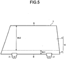
- Fig. 5 is a front view illustrating the glass article fabricated in Example 1.
- a width W-2 of the film in the second coverage area 5 formed in a main area of a principal surface of the glass plate 1 which extends from the upper edge A toward the lower edge B of the glass plate 1 is 50 cm
- a width W-1 of the film in the first coverage area 4 formed on a lower side of the second coverage area 5 along the lower edge B is 4 cm
- the holders 2 were provided within the area of the first coverage area 4.
- Table 1 lists a maximum film thickness and a minimum film thickness of the second coverage area 5 and a maximum film thickness and a minimum film thickness of the first coverage area 4 of the functional film 6.
- an area of the maximum film thickness of the second coverage area 5 of the functional film 6 is an area adjacent to the first coverage area 4 along the lower edge of the second coverage area 5, while an area of the minimum film thickness of the second coverage area 5 is an area along the upper edge A of the glass plate 1.
- an area of the maximum film thickness of the first coverage area 4 is an area along the lower edge B of the glass plate 1 since the film thickness of the first coverage area 4 is almost uniform in this example.
- Positions and widths of the first coverage area and the second coverage area, the maximum film thickness and the minimum film thickness of the second coverage area 5, the maximum film thickness and the minimum film thickness of the first coverage area 4, and so on which are described above are the same also in Examples 2 to 4.
- the maximum film thickness of the first coverage area is preferably 1.0 ⁇ m or less and more preferably 0.5 ⁇ m or less.
- a boundary line portion between the first coverage area and the second coverage area is placed at a lower end of an opening portion of a window when the glass article is mounted on the window of an automobile vehicle.
- the liquid composition 1 was applied to a concave surface of a glass plate by a flow coating method.
- the coating solution was able to be applied without coating omission while liquid splitting was suppressed. Besides, flowing-out of the coating solution to a convex surface did not occur.
- the glass plate on which the coating solution was applied was held with the concave surface upward, and thereafter, from a lower edge toward an upper edge of the concave surface of the glass plate, a part of the coating solution in a certain area (a lower edge area with a width of 4 cm from the lower edge toward the upper edge) was removed by using a blade.
- the glass plate was loaded onto a conveyer with the concave surface downward and sent to a heating furnace to be dried, whereby on the concave surface of the glass plate there was formed a functional film having a first coverage area having a first film thickness and a second coverage area having a second film thickness whose maximum film thickness is larger than the first film thickness. After taken out from the heating furnace, the glass plate was conveyed with the concave surface thereof upward.
- the liquid composition 3 was applied to a concave surface of a glass plate by a flow coating method.
- the coating solution was able to be applied without coating omission while liquid splitting was suppressed. Besides, flowing-out of the coating solution to a convex surface did not occur.
- the glass plate on which the coating solution was applied was held with the concave surface upward, and thereafter, from a lower edge toward an upper edge of the concave surface of the glass plate, a part of the coating solution in a certain area (a lower edge area with a width of 4 cm from the lower edge toward the upper edge) was removed by using a blade.
- the glass plate was loaded onto a conveyer with the concave surface downward and sent to a heating furnace to be dried, whereby on the concave surface of the glass plate there was formed a functional film having a first coverage area having a first film thickness and a second coverage area having a second film thickness whose maximum film thickness is larger than the first film thickness. After taken out from the heating furnace, the glass plate was conveyed with the concave surface thereof upward.
- a holder to whose recessed portion a polyurethane-based adhesive is applied was pushed from a lower portion of the glass plate in a manner to cover a part of the first coverage area of the functional film. Thereafter, the glass plate with the holder was put into a drying furnace to cure the adhesive. Thereby, a glass article was fabricated.
- the liquid composition 4 was applied to a concave surface of a glass plate by a flow coating method.
- the coating solution was able to be applied without coating omission while liquid splitting was suppressed. Besides, flowing-out of the coating solution to a convex surface did not occur.
- the glass plate on which the coating solution was applied was held with the concave surface upward, and thereafter, from a lower edge toward an upper edge of the concave surface of the glass plate, a part of the coating solution in a certain area (a lower edge area with a width of 4 cm from the lower edge toward the upper edge) was removed by using a blade.
- the glass plate was loaded onto a conveyer with the concave surface downward and sent to a heating furnace to be dried, whereby on the concave surface of the glass plate there was formed a functional film having a first coverage area having a first film thickness and a second coverage area having a second film thickness whose maximum film thickness is larger than the first film thickness. After taken out from the heating furnace, the glass plate was conveyed with the concave surface thereof upward.
- a holder to whose recessed portion a polyurethane-based adhesive is applied was pushed from a lower portion of the glass plate in a manner to cover a part of the first coverage area of the functional film. Thereafter, the glass plate with the holder was put into a drying furnace to cure the adhesive. Thereby, a glass article was fabricated.
- the liquid composition 1 was applied to a concave surface of a glass plate by a flow coating method.
- the coating solution was able to be applied without coating omission while liquid splitting was suppressed. Besides, flowing-out of the coating solution to a convex surface did not occur.
- the glass plate on which the coating solution was applied was held with the concave surface upward, and thereafter, loaded onto a conveyer with the concave surface downward and sent to a heating furnace to be dried, whereby a functional film was formed on the concave surface of the glass plate. After taken out from the heating furnace, the glass plate was conveyed with the concave surface thereof upward.
- the formed functional film was held with the concave surface upward in relation to the glass plate on which the coating solution was applied, and thereafter, a part of the coating solution in a certain area was not removed from a lower edge toward an upper edge of the glass plate by using a blade, so that there exists neither a first coverage area having a first film thickness nor a second coverage area having a second film thickness whose maximum film thickness is larger than the first film thickness as in Example 1 to Example 4.
- a holder to whose recessed portion a polyurethane-based adhesive is applied was pushed from a lower portion of the glass plate in a manner to cover a part of the functional film. Thereafter, the glass plate with the holder was put into a drying furnace to cure the adhesive. Thereby, a glass article was fabricated.
- a film thickness of a holder mounting portion thereof is about 10000 nm, which is larger than film thicknesses of the first coverage areas of Examples 1 to 4, and non-uniformity of film thicknesses was found in a surface.
- the liquid composition 6 was applied to a concave surface of a glass plate by a flow coating method.
- the coating solution was able to be applied without coating omission while liquid splitting was suppressed. Besides, flowing-out of the coating solution to a convex surface did not occur.
- the glass plate to which the coating solution was applied was held with the concave surface upward, and thereafter, loaded onto a conveyer with the concave surface downward and sent to a heating furnace to be dried, whereby a functional film was formed on the concave surface of the glass plate. After taken out from the heating furnace, the glass plate was conveyed with the concave surface thereof upward.
- Example 4 In the formed functional film, similar to in Example 5, a part of the coating solution in a certain area was not removed from a lower edge toward an upper edge of the glass plate by using a blade or the like, so that there exists neither a first coverage area having a first film thickness nor a second coverage area having a second film thickness whose maximum film thickness is larger than the first film thickness, as in Example 1 to Example 4.
- a holder to whose recessed portion a polyurethane-based adhesive is applied was pushed from a lower portion of the glass plate in a manner to cover a part of the functional film. Thereafter, the glass plate with the holder was put into a drying furnace to cure the adhesive. Thereby, a glass article was fabricated.
- a film thickness of a holder mounting portion thereof is about 10000 nm, which is larger than film thicknesses of the first coverage areas of Examples 1 to 4, and non-uniformity of film thickness was found in a surface.
- the glass plate with the holder was put into the drying furnace to cure the adhesive, and thereafter, the glass article was obtained. Subsequently, existence or absence of peeling of the functional film from the glass plate was visually confirmed. Evaluation criteria are listed below.
- Example 1 to Example 6 Each of the glass articles obtained in Example 1 to Example 6 was subjected to the accelerated weathering test in which the glass article was left for 1000 hours in the super xenon weather meter (SX75 by Suga Test Instruments Co., Ltd.) whose condition was set as 150W/m 2 (300 to 400 nm) in irradiance, 83 °C in black panel temperature, and 50 RH% in humidity.
- SX75 super xenon weather meter
- Example 1 to Example 6 Each of the glass articles obtained in Example 1 to Example 6 was subjected to the abrasion test of 1000 rotation by the CS-10F abrasion wheel in accordance with JIS-R3212 (year 1998).
- spectral characteristics of the minimum film thickness portion of the second coverage area and another portion of the second coverage area of the functional film before the accelerated weathering test were measured by using a spectrophotometer (U-4100 manufactured by Hitachi, Ltd.), and ultraviolet transmittances (Tuv[%]) were calculated based on ISO-9050 (year 1990) respectively.
- the ultraviolet transmittance of the minimum film thickness portion of the second coverage area was defined as Tuv 1 [%].
- the portion whose Tuv[%] was 1.0[%] in the second coverage area of the functional film before the accelerated weathering test was subjected to the accelerated weathering test the spectral characteristic was measured by using the spectrophotometer (U-4100 manufactured by Hitachi, Ltd.) after the test, and the ultraviolet transmittance (Tuv[%]) was calculated based on ISO-9050 (year 1990).
- the ultraviolet transmittance after the test was defined as Tuv 2 [%].
- the haze values[%] of the maximum film thickness portion of the second coverage area of the functional film before and after the Taber abrasion test were measured by a haze meter (Haze Gard Plus manufactured by BYK-Gardner).
- the haze value of the maximum film thickness portion in the second coverage area before the test was defined as H 1 [%]
- the haze value of that portion after the test was defined as H 2 [%]
- Table 1 shows that peeling of the functional film from the glass plate did not occur in each of Example 1 to Example 4. Further, Tuv 1 was 3.0% or less, Tuv 2 after the accelerated weathering test was 4.0% or less, H 1 before the Taber abrasion test was 1.0% or less, and ⁇ H before and after the Taber abrasion test was 5.0% or less.
- Example 6 the haze value was unmeasurable due to peeling of the functional film from the glass plate after the Taber abrasion test.
- a glass article of the present invention has both excellent ultraviolet absorbing ability and abrasion resistance. Therefore, the glass article of the present invention can be applied to a window glass for a vehicle of an automobile or the like, a window glass for a construction material mounted on a structure such as a building, and the like.
Landscapes
- Chemical & Material Sciences (AREA)
- Engineering & Computer Science (AREA)
- Life Sciences & Earth Sciences (AREA)
- Chemical Kinetics & Catalysis (AREA)
- General Chemical & Material Sciences (AREA)
- Geochemistry & Mineralogy (AREA)
- Materials Engineering (AREA)
- Organic Chemistry (AREA)
- Inorganic Chemistry (AREA)
- Composite Materials (AREA)
- Mechanical Engineering (AREA)
- Surface Treatment Of Glass (AREA)
Applications Claiming Priority (2)
| Application Number | Priority Date | Filing Date | Title |
|---|---|---|---|
| JP2015227439 | 2015-11-20 | ||
| PCT/JP2016/084265 WO2017086438A1 (ja) | 2015-11-20 | 2016-11-18 | ガラス物品 |
Publications (3)
| Publication Number | Publication Date |
|---|---|
| EP3379014A1 true EP3379014A1 (de) | 2018-09-26 |
| EP3379014A4 EP3379014A4 (de) | 2019-07-24 |
| EP3379014B1 EP3379014B1 (de) | 2021-04-21 |
Family
ID=58718999
Family Applications (1)
| Application Number | Title | Priority Date | Filing Date |
|---|---|---|---|
| EP16866438.1A Active EP3379014B1 (de) | 2015-11-20 | 2016-11-18 | Glasartikel |
Country Status (5)
| Country | Link |
|---|---|
| US (1) | US10576808B2 (de) |
| EP (1) | EP3379014B1 (de) |
| JP (1) | JP6717320B2 (de) |
| CN (1) | CN108291420B (de) |
| WO (1) | WO2017086438A1 (de) |
Families Citing this family (5)
| Publication number | Priority date | Publication date | Assignee | Title |
|---|---|---|---|---|
| JP7147484B2 (ja) * | 2017-12-08 | 2022-10-05 | Agc株式会社 | ホルダ付きウインドウガラス及びその製造方法 |
| JP7080726B2 (ja) * | 2018-05-22 | 2022-06-06 | 日本板硝子株式会社 | ガラス積層体 |
| JP7607494B2 (ja) * | 2020-03-31 | 2024-12-27 | 日本板硝子株式会社 | 自動車用窓ガラス |
| CN116056925A (zh) * | 2020-08-07 | 2023-05-02 | 旭硝子欧洲玻璃公司 | 包括窗户保持器的车辆窗户 |
| JP7719380B2 (ja) * | 2020-10-07 | 2025-08-06 | Agc株式会社 | 車両用ガラス及びその製造方法 |
Family Cites Families (15)
| Publication number | Priority date | Publication date | Assignee | Title |
|---|---|---|---|---|
| JPS5733197A (en) | 1980-07-29 | 1982-02-23 | Toyo Umpanki Co Ltd | Method of adjusting pneumatic pressure of front wheel in front wheel six wheel type forklift |
| US4987699A (en) * | 1989-08-24 | 1991-01-29 | Gold Peter N | Mounting for an automotive window panel |
| US5765310A (en) * | 1996-10-01 | 1998-06-16 | Gold; Peter N. | Frangible vehicle window panel mounting bracket |
| JP3473833B2 (ja) * | 1999-07-01 | 2003-12-08 | セントラル硝子株式会社 | 自動車用部分撥水ガラスおよびその製造方法 |
| US6044589A (en) * | 1999-09-14 | 2000-04-04 | Saturn Corporation | Motor vehicle window mounting apparatus |
| US6170197B1 (en) * | 1999-10-08 | 2001-01-09 | Delphi Technologies, Inc. | Window regulator mechanism |
| KR100487073B1 (ko) * | 2001-10-16 | 2005-05-03 | 가부시키가이샤 니프코 | 유리홀더 및 유리장착방법 |
| US7340861B2 (en) * | 2003-12-18 | 2008-03-11 | Chrysler Llc | Integrated laminated glass attachment plate |
| JP4933780B2 (ja) * | 2006-01-17 | 2012-05-16 | 日本板硝子株式会社 | 車両用窓ガラス及びその製造方法 |
| JP4529922B2 (ja) * | 2006-03-09 | 2010-08-25 | 株式会社ファルテック | 車両用窓組立体の製造方法および窓ガラスホルダー |
| JP5071075B2 (ja) * | 2007-11-29 | 2012-11-14 | 旭硝子株式会社 | 車両用ガラス板ホルダ及びホルダ付き車両用ガラス板 |
| WO2012107968A1 (ja) * | 2011-02-07 | 2012-08-16 | 日本板硝子株式会社 | 紫外線遮蔽能を有するガラス物品および紫外線遮蔽膜形成用微粒子分散組成物 |
| JP5733197B2 (ja) * | 2011-12-22 | 2015-06-10 | 旭硝子株式会社 | 塗膜付き自動車用窓ガラスおよびその製造方法 |
| JP5867529B2 (ja) * | 2014-03-04 | 2016-02-24 | 旭硝子株式会社 | 被膜付き自動車用窓ガラス |
| JP7147484B2 (ja) * | 2017-12-08 | 2022-10-05 | Agc株式会社 | ホルダ付きウインドウガラス及びその製造方法 |
-
2016
- 2016-11-18 WO PCT/JP2016/084265 patent/WO2017086438A1/ja not_active Ceased
- 2016-11-18 EP EP16866438.1A patent/EP3379014B1/de active Active
- 2016-11-18 JP JP2017551946A patent/JP6717320B2/ja active Active
- 2016-11-18 CN CN201680067589.4A patent/CN108291420B/zh active Active
-
2018
- 2018-04-09 US US15/948,067 patent/US10576808B2/en active Active
Also Published As
| Publication number | Publication date |
|---|---|
| EP3379014A4 (de) | 2019-07-24 |
| EP3379014B1 (de) | 2021-04-21 |
| JP6717320B2 (ja) | 2020-07-01 |
| CN108291420B (zh) | 2020-08-07 |
| US10576808B2 (en) | 2020-03-03 |
| JPWO2017086438A1 (ja) | 2018-09-06 |
| WO2017086438A1 (ja) | 2017-05-26 |
| US20180222291A1 (en) | 2018-08-09 |
| CN108291420A (zh) | 2018-07-17 |
Similar Documents
| Publication | Publication Date | Title |
|---|---|---|
| US10576808B2 (en) | Glass article | |
| EP2431433B1 (de) | Beschichtungsflüssigkeit zur formung eines ultraviolettstrahlung absorbierenden films und ultraviolettstrahlung absorbierender glasartikel | |
| EP3156227B1 (de) | Transparenter artikel mit beschlagschutzbeschichtung | |
| US8299169B2 (en) | Coating fluid applicable by hand for sol-gel film formation | |
| EP2674403A1 (de) | Glasartikel mit uv-strahlenabschirmung und mikropartikeldispergierte zusammensetzung zur herstellung einer uv-strahlenabschirmungsfolie | |
| US8216670B2 (en) | Heat ray shielding glass for vehicle and process for producing the same | |
| EP1949978B1 (de) | Verfahren zur herstellung von basismaterial zur bildung eines wärmeschutzfilms | |
| US7771831B2 (en) | Infrared shielding film-coated glass plate and process for its production | |
| CN101346318B (zh) | 车辆窗玻璃及其制造方法 | |
| US7754335B2 (en) | Vehicle window glass and process for manufacturing the same | |
| JP6625609B2 (ja) | 透明物品とその製造方法、及びそれに用いる膜形成溶液 | |
| KR101916503B1 (ko) | 발수성 박막용 조성물, 이를 이용한 발수성 박막 및 그 제조방법 | |
| JP2011136846A (ja) | 紫外線遮蔽能を有するガラス物品 | |
| JP7827059B2 (ja) | ガラス積層体とその製造方法 | |
| CN113260598A (zh) | 紫外线遮蔽玻璃 | |
| JP7484786B2 (ja) | ガラス積層体とその製造方法 | |
| JP2024030759A (ja) | ガラス積層体とその製造方法 | |
| EP3587370A1 (de) | Verfahren zur herstellung von farbbeschichtetem flachglas | |
| JP2008255192A (ja) | 防曇性被膜形成塗布液、防曇性被膜及び防曇性被膜の形成方法 | |
| JP2024066990A (ja) | ガラス積層体とその製造方法 | |
| JP2024113661A (ja) | ガラス積層体 | |
| CN113840727A (zh) | 具有防晒涂层的交通工具装配玻璃 | |
| JP2010120838A (ja) | 吸水性の薄膜及び該薄膜を含む表示装置用カバーガラス | |
| KR20190033173A (ko) | 발수성이 우수하고 uv 경화가 가능한 박막용 조성물 및 이로부터 제조된 발수성 박막 |
Legal Events
| Date | Code | Title | Description |
|---|---|---|---|
| STAA | Information on the status of an ep patent application or granted ep patent |
Free format text: STATUS: THE INTERNATIONAL PUBLICATION HAS BEEN MADE |
|
| PUAI | Public reference made under article 153(3) epc to a published international application that has entered the european phase |
Free format text: ORIGINAL CODE: 0009012 |
|
| STAA | Information on the status of an ep patent application or granted ep patent |
Free format text: STATUS: REQUEST FOR EXAMINATION WAS MADE |
|
| 17P | Request for examination filed |
Effective date: 20180419 |
|
| AK | Designated contracting states |
Kind code of ref document: A1 Designated state(s): AL AT BE BG CH CY CZ DE DK EE ES FI FR GB GR HR HU IE IS IT LI LT LU LV MC MK MT NL NO PL PT RO RS SE SI SK SM TR |
|
| AX | Request for extension of the european patent |
Extension state: BA ME |
|
| DAV | Request for validation of the european patent (deleted) | ||
| DAX | Request for extension of the european patent (deleted) | ||
| A4 | Supplementary search report drawn up and despatched |
Effective date: 20190621 |
|
| RIC1 | Information provided on ipc code assigned before grant |
Ipc: C03C 17/00 20060101AFI20190614BHEP Ipc: E05F 11/38 20060101ALN20190614BHEP Ipc: E05F 11/44 20060101ALI20190614BHEP |
|
| RIC1 | Information provided on ipc code assigned before grant |
Ipc: E05F 11/38 20060101ALN20190723BHEP Ipc: C03C 17/00 20060101AFI20190723BHEP Ipc: E05F 11/44 20060101ALI20190723BHEP |
|
| REG | Reference to a national code |
Ref country code: DE Ref legal event code: R079 Ref document number: 602016056659 Country of ref document: DE Free format text: PREVIOUS MAIN CLASS: E05F0011380000 Ipc: C03C0017000000 |
|
| GRAP | Despatch of communication of intention to grant a patent |
Free format text: ORIGINAL CODE: EPIDOSNIGR1 |
|
| STAA | Information on the status of an ep patent application or granted ep patent |
Free format text: STATUS: GRANT OF PATENT IS INTENDED |
|
| RIC1 | Information provided on ipc code assigned before grant |
Ipc: C03C 17/00 20060101AFI20201112BHEP Ipc: E05F 11/44 20060101ALI20201112BHEP Ipc: E05F 11/38 20060101ALN20201112BHEP |
|
| RIC1 | Information provided on ipc code assigned before grant |
Ipc: C03C 17/00 20060101AFI20201113BHEP Ipc: E05F 11/44 20060101ALI20201113BHEP Ipc: E05F 11/38 20060101ALN20201113BHEP |
|
| INTG | Intention to grant announced |
Effective date: 20201202 |
|
| GRAS | Grant fee paid |
Free format text: ORIGINAL CODE: EPIDOSNIGR3 |
|
| GRAA | (expected) grant |
Free format text: ORIGINAL CODE: 0009210 |
|
| STAA | Information on the status of an ep patent application or granted ep patent |
Free format text: STATUS: THE PATENT HAS BEEN GRANTED |
|
| AK | Designated contracting states |
Kind code of ref document: B1 Designated state(s): AL AT BE BG CH CY CZ DE DK EE ES FI FR GB GR HR HU IE IS IT LI LT LU LV MC MK MT NL NO PL PT RO RS SE SI SK SM TR |
|
| REG | Reference to a national code |
Ref country code: GB Ref legal event code: FG4D |
|
| REG | Reference to a national code |
Ref country code: CH Ref legal event code: EP |
|
| REG | Reference to a national code |
Ref country code: DE Ref legal event code: R096 Ref document number: 602016056659 Country of ref document: DE Ref country code: IE Ref legal event code: FG4D |
|
| REG | Reference to a national code |
Ref country code: AT Ref legal event code: REF Ref document number: 1384465 Country of ref document: AT Kind code of ref document: T Effective date: 20210515 |
|
| REG | Reference to a national code |
Ref country code: LT Ref legal event code: MG9D |
|
| REG | Reference to a national code |
Ref country code: AT Ref legal event code: MK05 Ref document number: 1384465 Country of ref document: AT Kind code of ref document: T Effective date: 20210421 |
|
| REG | Reference to a national code |
Ref country code: NL Ref legal event code: MP Effective date: 20210421 |
|
| PG25 | Lapsed in a contracting state [announced via postgrant information from national office to epo] |
Ref country code: FI Free format text: LAPSE BECAUSE OF FAILURE TO SUBMIT A TRANSLATION OF THE DESCRIPTION OR TO PAY THE FEE WITHIN THE PRESCRIBED TIME-LIMIT Effective date: 20210421 Ref country code: LT Free format text: LAPSE BECAUSE OF FAILURE TO SUBMIT A TRANSLATION OF THE DESCRIPTION OR TO PAY THE FEE WITHIN THE PRESCRIBED TIME-LIMIT Effective date: 20210421 Ref country code: NL Free format text: LAPSE BECAUSE OF FAILURE TO SUBMIT A TRANSLATION OF THE DESCRIPTION OR TO PAY THE FEE WITHIN THE PRESCRIBED TIME-LIMIT Effective date: 20210421 Ref country code: BG Free format text: LAPSE BECAUSE OF FAILURE TO SUBMIT A TRANSLATION OF THE DESCRIPTION OR TO PAY THE FEE WITHIN THE PRESCRIBED TIME-LIMIT Effective date: 20210721 Ref country code: AT Free format text: LAPSE BECAUSE OF FAILURE TO SUBMIT A TRANSLATION OF THE DESCRIPTION OR TO PAY THE FEE WITHIN THE PRESCRIBED TIME-LIMIT Effective date: 20210421 Ref country code: HR Free format text: LAPSE BECAUSE OF FAILURE TO SUBMIT A TRANSLATION OF THE DESCRIPTION OR TO PAY THE FEE WITHIN THE PRESCRIBED TIME-LIMIT Effective date: 20210421 |
|
| PG25 | Lapsed in a contracting state [announced via postgrant information from national office to epo] |
Ref country code: GR Free format text: LAPSE BECAUSE OF FAILURE TO SUBMIT A TRANSLATION OF THE DESCRIPTION OR TO PAY THE FEE WITHIN THE PRESCRIBED TIME-LIMIT Effective date: 20210722 Ref country code: IS Free format text: LAPSE BECAUSE OF FAILURE TO SUBMIT A TRANSLATION OF THE DESCRIPTION OR TO PAY THE FEE WITHIN THE PRESCRIBED TIME-LIMIT Effective date: 20210821 Ref country code: LV Free format text: LAPSE BECAUSE OF FAILURE TO SUBMIT A TRANSLATION OF THE DESCRIPTION OR TO PAY THE FEE WITHIN THE PRESCRIBED TIME-LIMIT Effective date: 20210421 Ref country code: PL Free format text: LAPSE BECAUSE OF FAILURE TO SUBMIT A TRANSLATION OF THE DESCRIPTION OR TO PAY THE FEE WITHIN THE PRESCRIBED TIME-LIMIT Effective date: 20210421 Ref country code: NO Free format text: LAPSE BECAUSE OF FAILURE TO SUBMIT A TRANSLATION OF THE DESCRIPTION OR TO PAY THE FEE WITHIN THE PRESCRIBED TIME-LIMIT Effective date: 20210721 Ref country code: PT Free format text: LAPSE BECAUSE OF FAILURE TO SUBMIT A TRANSLATION OF THE DESCRIPTION OR TO PAY THE FEE WITHIN THE PRESCRIBED TIME-LIMIT Effective date: 20210823 Ref country code: RS Free format text: LAPSE BECAUSE OF FAILURE TO SUBMIT A TRANSLATION OF THE DESCRIPTION OR TO PAY THE FEE WITHIN THE PRESCRIBED TIME-LIMIT Effective date: 20210421 Ref country code: SE Free format text: LAPSE BECAUSE OF FAILURE TO SUBMIT A TRANSLATION OF THE DESCRIPTION OR TO PAY THE FEE WITHIN THE PRESCRIBED TIME-LIMIT Effective date: 20210421 |
|
| REG | Reference to a national code |
Ref country code: DE Ref legal event code: R097 Ref document number: 602016056659 Country of ref document: DE |
|
| PG25 | Lapsed in a contracting state [announced via postgrant information from national office to epo] |
Ref country code: SK Free format text: LAPSE BECAUSE OF FAILURE TO SUBMIT A TRANSLATION OF THE DESCRIPTION OR TO PAY THE FEE WITHIN THE PRESCRIBED TIME-LIMIT Effective date: 20210421 Ref country code: SM Free format text: LAPSE BECAUSE OF FAILURE TO SUBMIT A TRANSLATION OF THE DESCRIPTION OR TO PAY THE FEE WITHIN THE PRESCRIBED TIME-LIMIT Effective date: 20210421 Ref country code: EE Free format text: LAPSE BECAUSE OF FAILURE TO SUBMIT A TRANSLATION OF THE DESCRIPTION OR TO PAY THE FEE WITHIN THE PRESCRIBED TIME-LIMIT Effective date: 20210421 Ref country code: CZ Free format text: LAPSE BECAUSE OF FAILURE TO SUBMIT A TRANSLATION OF THE DESCRIPTION OR TO PAY THE FEE WITHIN THE PRESCRIBED TIME-LIMIT Effective date: 20210421 Ref country code: DK Free format text: LAPSE BECAUSE OF FAILURE TO SUBMIT A TRANSLATION OF THE DESCRIPTION OR TO PAY THE FEE WITHIN THE PRESCRIBED TIME-LIMIT Effective date: 20210421 Ref country code: ES Free format text: LAPSE BECAUSE OF FAILURE TO SUBMIT A TRANSLATION OF THE DESCRIPTION OR TO PAY THE FEE WITHIN THE PRESCRIBED TIME-LIMIT Effective date: 20210421 Ref country code: RO Free format text: LAPSE BECAUSE OF FAILURE TO SUBMIT A TRANSLATION OF THE DESCRIPTION OR TO PAY THE FEE WITHIN THE PRESCRIBED TIME-LIMIT Effective date: 20210421 |
|
| PLBE | No opposition filed within time limit |
Free format text: ORIGINAL CODE: 0009261 |
|
| STAA | Information on the status of an ep patent application or granted ep patent |
Free format text: STATUS: NO OPPOSITION FILED WITHIN TIME LIMIT |
|
| 26N | No opposition filed |
Effective date: 20220124 |
|
| PG25 | Lapsed in a contracting state [announced via postgrant information from national office to epo] |
Ref country code: IS Free format text: LAPSE BECAUSE OF FAILURE TO SUBMIT A TRANSLATION OF THE DESCRIPTION OR TO PAY THE FEE WITHIN THE PRESCRIBED TIME-LIMIT Effective date: 20210821 Ref country code: AL Free format text: LAPSE BECAUSE OF FAILURE TO SUBMIT A TRANSLATION OF THE DESCRIPTION OR TO PAY THE FEE WITHIN THE PRESCRIBED TIME-LIMIT Effective date: 20210421 |
|
| PG25 | Lapsed in a contracting state [announced via postgrant information from national office to epo] |
Ref country code: MC Free format text: LAPSE BECAUSE OF FAILURE TO SUBMIT A TRANSLATION OF THE DESCRIPTION OR TO PAY THE FEE WITHIN THE PRESCRIBED TIME-LIMIT Effective date: 20210421 |
|
| REG | Reference to a national code |
Ref country code: CH Ref legal event code: PL |
|
| GBPC | Gb: european patent ceased through non-payment of renewal fee |
Effective date: 20211118 |
|
| PG25 | Lapsed in a contracting state [announced via postgrant information from national office to epo] |
Ref country code: LU Free format text: LAPSE BECAUSE OF NON-PAYMENT OF DUE FEES Effective date: 20211118 Ref country code: IT Free format text: LAPSE BECAUSE OF FAILURE TO SUBMIT A TRANSLATION OF THE DESCRIPTION OR TO PAY THE FEE WITHIN THE PRESCRIBED TIME-LIMIT Effective date: 20210421 Ref country code: BE Free format text: LAPSE BECAUSE OF NON-PAYMENT OF DUE FEES Effective date: 20211130 |
|
| REG | Reference to a national code |
Ref country code: BE Ref legal event code: MM Effective date: 20211130 |
|
| PG25 | Lapsed in a contracting state [announced via postgrant information from national office to epo] |
Ref country code: LI Free format text: LAPSE BECAUSE OF NON-PAYMENT OF DUE FEES Effective date: 20211130 Ref country code: CH Free format text: LAPSE BECAUSE OF NON-PAYMENT OF DUE FEES Effective date: 20211130 |
|
| PG25 | Lapsed in a contracting state [announced via postgrant information from national office to epo] |
Ref country code: IE Free format text: LAPSE BECAUSE OF NON-PAYMENT OF DUE FEES Effective date: 20211118 Ref country code: GB Free format text: LAPSE BECAUSE OF NON-PAYMENT OF DUE FEES Effective date: 20211118 |
|
| PG25 | Lapsed in a contracting state [announced via postgrant information from national office to epo] |
Ref country code: FR Free format text: LAPSE BECAUSE OF NON-PAYMENT OF DUE FEES Effective date: 20211130 |
|
| PG25 | Lapsed in a contracting state [announced via postgrant information from national office to epo] |
Ref country code: HU Free format text: LAPSE BECAUSE OF FAILURE TO SUBMIT A TRANSLATION OF THE DESCRIPTION OR TO PAY THE FEE WITHIN THE PRESCRIBED TIME-LIMIT; INVALID AB INITIO Effective date: 20161118 |
|
| PG25 | Lapsed in a contracting state [announced via postgrant information from national office to epo] |
Ref country code: CY Free format text: LAPSE BECAUSE OF FAILURE TO SUBMIT A TRANSLATION OF THE DESCRIPTION OR TO PAY THE FEE WITHIN THE PRESCRIBED TIME-LIMIT Effective date: 20210421 |
|
| PGFP | Annual fee paid to national office [announced via postgrant information from national office to epo] |
Ref country code: DE Payment date: 20231121 Year of fee payment: 8 |
|
| PG25 | Lapsed in a contracting state [announced via postgrant information from national office to epo] |
Ref country code: MK Free format text: LAPSE BECAUSE OF FAILURE TO SUBMIT A TRANSLATION OF THE DESCRIPTION OR TO PAY THE FEE WITHIN THE PRESCRIBED TIME-LIMIT Effective date: 20210421 |
|
| PG25 | Lapsed in a contracting state [announced via postgrant information from national office to epo] |
Ref country code: MT Free format text: LAPSE BECAUSE OF FAILURE TO SUBMIT A TRANSLATION OF THE DESCRIPTION OR TO PAY THE FEE WITHIN THE PRESCRIBED TIME-LIMIT Effective date: 20210421 |
|
| REG | Reference to a national code |
Ref country code: DE Ref legal event code: R119 Ref document number: 602016056659 Country of ref document: DE |
|
| PG25 | Lapsed in a contracting state [announced via postgrant information from national office to epo] |
Ref country code: DE Free format text: LAPSE BECAUSE OF NON-PAYMENT OF DUE FEES Effective date: 20250603 |
|
| PG25 | Lapsed in a contracting state [announced via postgrant information from national office to epo] |
Ref country code: TR Free format text: LAPSE BECAUSE OF FAILURE TO SUBMIT A TRANSLATION OF THE DESCRIPTION OR TO PAY THE FEE WITHIN THE PRESCRIBED TIME-LIMIT Effective date: 20210421 |