EP3378617B1 - Granulate enthaltend ein fluorharz, deren verwendung sowie verfahren zur herstellung eines stromkabels damit - Google Patents
Granulate enthaltend ein fluorharz, deren verwendung sowie verfahren zur herstellung eines stromkabels damit Download PDFInfo
- Publication number
- EP3378617B1 EP3378617B1 EP17741377.0A EP17741377A EP3378617B1 EP 3378617 B1 EP3378617 B1 EP 3378617B1 EP 17741377 A EP17741377 A EP 17741377A EP 3378617 B1 EP3378617 B1 EP 3378617B1
- Authority
- EP
- European Patent Office
- Prior art keywords
- pellets
- fluororesin
- groups
- pellet
- cylinder
- Prior art date
- Legal status (The legal status is an assumption and is not a legal conclusion. Google has not performed a legal analysis and makes no representation as to the accuracy of the status listed.)
- Active
Links
Images

Classifications
-
- B—PERFORMING OPERATIONS; TRANSPORTING
- B29—WORKING OF PLASTICS; WORKING OF SUBSTANCES IN A PLASTIC STATE IN GENERAL
- B29B—PREPARATION OR PRETREATMENT OF THE MATERIAL TO BE SHAPED; MAKING GRANULES OR PREFORMS; RECOVERY OF PLASTICS OR OTHER CONSTITUENTS OF WASTE MATERIAL CONTAINING PLASTICS
- B29B9/00—Making granules
- B29B9/02—Making granules by dividing preformed material
- B29B9/06—Making granules by dividing preformed material in the form of filamentary material, e.g. combined with extrusion
-
- C—CHEMISTRY; METALLURGY
- C08—ORGANIC MACROMOLECULAR COMPOUNDS; THEIR PREPARATION OR CHEMICAL WORKING-UP; COMPOSITIONS BASED THEREON
- C08F—MACROMOLECULAR COMPOUNDS OBTAINED BY REACTIONS ONLY INVOLVING CARBON-TO-CARBON UNSATURATED BONDS
- C08F214/00—Copolymers of compounds having one or more unsaturated aliphatic radicals, each having only one carbon-to-carbon double bond, and at least one being terminated by a halogen
- C08F214/18—Monomers containing fluorine
- C08F214/28—Hexyfluoropropene
- C08F214/282—Hexyfluoropropene with fluorinated vinyl ethers
-
- B—PERFORMING OPERATIONS; TRANSPORTING
- B29—WORKING OF PLASTICS; WORKING OF SUBSTANCES IN A PLASTIC STATE IN GENERAL
- B29B—PREPARATION OR PRETREATMENT OF THE MATERIAL TO BE SHAPED; MAKING GRANULES OR PREFORMS; RECOVERY OF PLASTICS OR OTHER CONSTITUENTS OF WASTE MATERIAL CONTAINING PLASTICS
- B29B9/00—Making granules
- B29B9/16—Auxiliary treatment of granules
-
- B—PERFORMING OPERATIONS; TRANSPORTING
- B29—WORKING OF PLASTICS; WORKING OF SUBSTANCES IN A PLASTIC STATE IN GENERAL
- B29B—PREPARATION OR PRETREATMENT OF THE MATERIAL TO BE SHAPED; MAKING GRANULES OR PREFORMS; RECOVERY OF PLASTICS OR OTHER CONSTITUENTS OF WASTE MATERIAL CONTAINING PLASTICS
- B29B11/00—Making preforms
- B29B11/06—Making preforms by moulding the material
- B29B11/10—Extrusion moulding
-
- B—PERFORMING OPERATIONS; TRANSPORTING
- B29—WORKING OF PLASTICS; WORKING OF SUBSTANCES IN A PLASTIC STATE IN GENERAL
- B29B—PREPARATION OR PRETREATMENT OF THE MATERIAL TO BE SHAPED; MAKING GRANULES OR PREFORMS; RECOVERY OF PLASTICS OR OTHER CONSTITUENTS OF WASTE MATERIAL CONTAINING PLASTICS
- B29B9/00—Making granules
- B29B9/12—Making granules characterised by structure or composition
-
- B—PERFORMING OPERATIONS; TRANSPORTING
- B29—WORKING OF PLASTICS; WORKING OF SUBSTANCES IN A PLASTIC STATE IN GENERAL
- B29C—SHAPING OR JOINING OF PLASTICS; SHAPING OF MATERIAL IN A PLASTIC STATE, NOT OTHERWISE PROVIDED FOR; AFTER-TREATMENT OF THE SHAPED PRODUCTS, e.g. REPAIRING
- B29C48/00—Extrusion moulding, i.e. expressing the moulding material through a die or nozzle which imparts the desired form; Apparatus therefor
- B29C48/03—Extrusion moulding, i.e. expressing the moulding material through a die or nozzle which imparts the desired form; Apparatus therefor characterised by the shape of the extruded material at extrusion
- B29C48/06—Rod-shaped
-
- B—PERFORMING OPERATIONS; TRANSPORTING
- B29—WORKING OF PLASTICS; WORKING OF SUBSTANCES IN A PLASTIC STATE IN GENERAL
- B29C—SHAPING OR JOINING OF PLASTICS; SHAPING OF MATERIAL IN A PLASTIC STATE, NOT OTHERWISE PROVIDED FOR; AFTER-TREATMENT OF THE SHAPED PRODUCTS, e.g. REPAIRING
- B29C48/00—Extrusion moulding, i.e. expressing the moulding material through a die or nozzle which imparts the desired form; Apparatus therefor
- B29C48/15—Extrusion moulding, i.e. expressing the moulding material through a die or nozzle which imparts the desired form; Apparatus therefor incorporating preformed parts or layers, e.g. extrusion moulding around inserts
- B29C48/154—Coating solid articles, i.e. non-hollow articles
-
- C—CHEMISTRY; METALLURGY
- C08—ORGANIC MACROMOLECULAR COMPOUNDS; THEIR PREPARATION OR CHEMICAL WORKING-UP; COMPOSITIONS BASED THEREON
- C08L—COMPOSITIONS OF MACROMOLECULAR COMPOUNDS
- C08L27/00—Compositions of homopolymers or copolymers of compounds having one or more unsaturated aliphatic radicals, each having only one carbon-to-carbon double bond, and at least one being terminated by a halogen; Compositions of derivatives of such polymers
- C08L27/02—Compositions of homopolymers or copolymers of compounds having one or more unsaturated aliphatic radicals, each having only one carbon-to-carbon double bond, and at least one being terminated by a halogen; Compositions of derivatives of such polymers not modified by chemical after-treatment
- C08L27/12—Compositions of homopolymers or copolymers of compounds having one or more unsaturated aliphatic radicals, each having only one carbon-to-carbon double bond, and at least one being terminated by a halogen; Compositions of derivatives of such polymers not modified by chemical after-treatment containing fluorine atoms
- C08L27/18—Homopolymers or copolymers or tetrafluoroethene
-
- H—ELECTRICITY
- H01—ELECTRIC ELEMENTS
- H01B—CABLES; CONDUCTORS; INSULATORS; SELECTION OF MATERIALS FOR THEIR CONDUCTIVE, INSULATING OR DIELECTRIC PROPERTIES
- H01B13/00—Apparatus or processes specially adapted for manufacturing conductors or cables
-
- H—ELECTRICITY
- H01—ELECTRIC ELEMENTS
- H01B—CABLES; CONDUCTORS; INSULATORS; SELECTION OF MATERIALS FOR THEIR CONDUCTIVE, INSULATING OR DIELECTRIC PROPERTIES
- H01B13/00—Apparatus or processes specially adapted for manufacturing conductors or cables
- H01B13/06—Insulating conductors or cables
- H01B13/14—Insulating conductors or cables by extrusion
- H01B13/147—Feeding of the insulating material
-
- H—ELECTRICITY
- H01—ELECTRIC ELEMENTS
- H01B—CABLES; CONDUCTORS; INSULATORS; SELECTION OF MATERIALS FOR THEIR CONDUCTIVE, INSULATING OR DIELECTRIC PROPERTIES
- H01B13/00—Apparatus or processes specially adapted for manufacturing conductors or cables
- H01B13/06—Insulating conductors or cables
- H01B13/14—Insulating conductors or cables by extrusion
- H01B13/148—Selection of the insulating material therefor
-
- H—ELECTRICITY
- H01—ELECTRIC ELEMENTS
- H01B—CABLES; CONDUCTORS; INSULATORS; SELECTION OF MATERIALS FOR THEIR CONDUCTIVE, INSULATING OR DIELECTRIC PROPERTIES
- H01B3/00—Insulators or insulating bodies characterised by the insulating materials; Selection of materials for their insulating or dielectric properties
- H01B3/18—Insulators or insulating bodies characterised by the insulating materials; Selection of materials for their insulating or dielectric properties mainly consisting of organic substances
- H01B3/30—Insulators or insulating bodies characterised by the insulating materials; Selection of materials for their insulating or dielectric properties mainly consisting of organic substances plastics; resins; waxes
- H01B3/42—Insulators or insulating bodies characterised by the insulating materials; Selection of materials for their insulating or dielectric properties mainly consisting of organic substances plastics; resins; waxes polyesters; polyethers; polyacetals
-
- H—ELECTRICITY
- H01—ELECTRIC ELEMENTS
- H01B—CABLES; CONDUCTORS; INSULATORS; SELECTION OF MATERIALS FOR THEIR CONDUCTIVE, INSULATING OR DIELECTRIC PROPERTIES
- H01B3/00—Insulators or insulating bodies characterised by the insulating materials; Selection of materials for their insulating or dielectric properties
- H01B3/18—Insulators or insulating bodies characterised by the insulating materials; Selection of materials for their insulating or dielectric properties mainly consisting of organic substances
- H01B3/30—Insulators or insulating bodies characterised by the insulating materials; Selection of materials for their insulating or dielectric properties mainly consisting of organic substances plastics; resins; waxes
- H01B3/44—Insulators or insulating bodies characterised by the insulating materials; Selection of materials for their insulating or dielectric properties mainly consisting of organic substances plastics; resins; waxes vinyl resins; acrylic resins
- H01B3/443—Insulators or insulating bodies characterised by the insulating materials; Selection of materials for their insulating or dielectric properties mainly consisting of organic substances plastics; resins; waxes vinyl resins; acrylic resins from vinylhalogenides or other halogenoethylenic compounds
- H01B3/445—Insulators or insulating bodies characterised by the insulating materials; Selection of materials for their insulating or dielectric properties mainly consisting of organic substances plastics; resins; waxes vinyl resins; acrylic resins from vinylhalogenides or other halogenoethylenic compounds from vinylfluorides or other fluoroethylenic compounds
-
- B—PERFORMING OPERATIONS; TRANSPORTING
- B29—WORKING OF PLASTICS; WORKING OF SUBSTANCES IN A PLASTIC STATE IN GENERAL
- B29B—PREPARATION OR PRETREATMENT OF THE MATERIAL TO BE SHAPED; MAKING GRANULES OR PREFORMS; RECOVERY OF PLASTICS OR OTHER CONSTITUENTS OF WASTE MATERIAL CONTAINING PLASTICS
- B29B9/00—Making granules
- B29B9/16—Auxiliary treatment of granules
- B29B2009/161—Absorbing, i.e. introducing a gas, a liquid or a solid material into the granules
-
- B—PERFORMING OPERATIONS; TRANSPORTING
- B29—WORKING OF PLASTICS; WORKING OF SUBSTANCES IN A PLASTIC STATE IN GENERAL
- B29C—SHAPING OR JOINING OF PLASTICS; SHAPING OF MATERIAL IN A PLASTIC STATE, NOT OTHERWISE PROVIDED FOR; AFTER-TREATMENT OF THE SHAPED PRODUCTS, e.g. REPAIRING
- B29C48/00—Extrusion moulding, i.e. expressing the moulding material through a die or nozzle which imparts the desired form; Apparatus therefor
- B29C48/25—Component parts, details or accessories; Auxiliary operations
- B29C48/30—Extrusion nozzles or dies
- B29C48/32—Extrusion nozzles or dies with annular openings, e.g. for forming tubular articles
- B29C48/34—Cross-head annular extrusion nozzles, i.e. for simultaneously receiving moulding material and the preform to be coated
-
- B—PERFORMING OPERATIONS; TRANSPORTING
- B29—WORKING OF PLASTICS; WORKING OF SUBSTANCES IN A PLASTIC STATE IN GENERAL
- B29L—INDEXING SCHEME ASSOCIATED WITH SUBCLASS B29C, RELATING TO PARTICULAR ARTICLES
- B29L2031/00—Other particular articles
- B29L2031/34—Electrical apparatus, e.g. sparking plugs or parts thereof
- B29L2031/3406—Components, e.g. resistors
Definitions
- the invention relates to fluororesin pellets.
- the invention also relates to electric wires formed using the pellets, and methods for producing electric wires using the pellets.
- Fluororesin pellets are used in many cases as materials for producing molded articles of a fluororesin in terms of handleability.
- Patent Literature 1 aims to provide a method for producing an insulated thin electric wire. This method enables insulated extrusion and coating with a very low amount of a material attached. In this method, the pellets have a size of 1.5 mm or smaller and the extruder has a screw outer diameter of 20 mm or smaller.
- Patent Literature 2 discloses cylindrical or elliptic cylindrical mini-pellets of a tetrafluoroethylene/perfluoroalkyl vinyl ether copolymer (PFA) which is a resin material for rotational molding. This material may suffer no metal contamination and can be sufficient in terms of the quality and performance of rotationally molded articles.
- PFA tetrafluoroethylene/perfluoroalkyl vinyl ether copolymer
- Patent Literature 3 discloses that fluororesin pellets are adjusted to have an average particle size of 1.0 to 5.0 mm in consideration of the handleability during production of fluororesin molded articles using fluororesin pellets.
- Patent Literature 4 relates to a method for producing an insulated electric cable with high foaming degree by using a foaming liquid containing water.
- a thermally melted resin placed under a pressure over the atmospheric pressure is mixed with water-containing foaming liquid having a boiling point lower than the melting point of the resin and the resin mixed with the foaming liquid is extruded while coating a conductor so that the resin mixture is released from pressure and subjected to forming.
- Patent Literature 5 describes a tetrafluoroethylene/hexafluoropropylene copolymer having an improved moldability in melt extrusion molding.
- the improved moldability gives rise to significant reduction of defects in high-speed extrusion coating of an electrical wire.
- the tetrafluoroethylene/hexafluoropropylene copolymer is obtained by polymerization of at least tetrafluoroethylene and hexafluoropropylene selected from the group consisting of tetrafluoroethylene, hexafluoropropylene and a third monomer, without mixing with a resin which has a melting point with a difference of 20°C or more from the melting point of the tetrafluoroethylene/hexafluoropropylene copolymer.
- Electric wire coating materials are required to have moldability into small-diameter electric wires and moldability into thin-wall electric wires.
- a slight variation in diameter of electric wires during molding inevitably affects the final physical properties of electric wires.
- the molding needs to be more stable than ever.
- Electric wire coating materials are also required to have better wire diameter stability and capacitance stability than conventional materials.
- fluororesin pellets are fed into a cylinder of an extruder from a hopper and molten in the cylinder, and then the molten fluororesin is extruded through a die onto a core wire that is delivered from the back of the die, whereby a coating layer is formed.
- the invention aims to provide novel pellets exhibiting high fluidity in a hopper of an extruder and are capable of forming a coating layer having good wire diameter stability and capacitance stability even when used for rapid molding of electric wire coating.
- the pellets satisfy that the major axis D 1 is 1.6 mm or longer and the minor axis D 2 is 1.6 mm or longer.
- the pellets preferably satisfy that the heights L have a standard deviation of 0.3 mm or smaller.
- the pellets preferably include not more than 100 pellets having an irregular shape for each 100 g of the pellets.
- the pellets preferably include 10 mass% or less of pellets containing bubbles therein for each 100 g of the pellets.
- 300 g of the pellets are discharged within 9.2 seconds in a pellet fluidity test.
- Each pellet preferably has a substantially spheroidal shape, a substantially cylindrical shape, or a substantially elliptic cylindrical shape.
- the fluororesin preferably contains 120 or less groups in total selected from -COOH, -COOCH 3 , -CH 2 OH, -COF, -CONH 2 , and -CF 2 H for each 1 ⁇ 10 6 carbon atoms.
- the invention also relates to use of the pellets for forming a coating layer disposed around a core wire of an electric wire, as claimed in claim 8.
- the invention also relates to a method according claim 9 for producing an electric wire including a core wire and a coating layer using an extruder provided with a cylinder, a screw contained in the cylinder, a die attached to a tip of the cylinder, and a hopper configured to feed pellets into the cylinder.
- the method includes: preparing the pellets; pouring the pellets into the hopper; feeding the pellets from the hopper into the cylinder; melting the pellets in the cylinder to form a molten fluororesin; and extruding the molten fluororesin through the die to form the coating layer on the core wire.
- the pellets of the invention have the aforementioned configuration, and thus have excellent fluidity in a hopper of an extruder.
- Use of the pellets of the invention as material for coating an electric wire enables production of an electric wire that includes a coating layer having good wire diameter stability and capacitance stability at high productivity.
- the electric wire of the invention has the aforementioned configuration, and thus has excellent wire diameter stability and capacitance stability.
- the method for producing an electric wire of the invention has the aforementioned configuration, and thus enables production of an electric wire having excellent wire diameter stability and capacitance stability at high productivity.
- Fig. 1 is a schematic view of the pellets placed on a horizontal surface and observed in the direction normal to the horizontal surface.
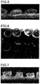
- Fig. 4 and Fig. 6 are pictures of the pellets of the invention placed on a horizontal surface taken in the direction normal to the horizontal surface.
- the pellets include a pellet 11 having a substantially circular outline and pellets 12 each having a substantially elliptic outline.
- the major axis D 1 and the minor axis D 2 are as shown in Fig. 1 .
- the major axis D 1 and the minor axis D 2 are the same length. Even when the lengths thereof are the same, the terms "major axis” and “minor axis” are used herein as a matter of convenience.
- the major axis D 1 and the minor axis D 2 can be determined by randomly selecting 20 g of pellets, placing them on a horizontal surface, measuring the major axis and minor axis of each pellet, and averaging the values.
- the above measurement needs to be performed such that the pellets are placed in such a manner that they neither roll nor fall even on a solid, smooth horizontal surface.
- the pellets are placed in such a manner that they neither roll nor fall even on a solid, smooth horizontal surface.
- the whole shape of a pellet is a substantially cylindrical shape and the pellet is placed on a horizontal surface with a side thereof in contact with the surface, it may stop moving. Still, the pellet will roll or fall when a weak vibration is applied.
- Such a manner of placement is inappropriate and the pellets need to be placed in a stable manner before the measurement.
- the pellets when the pellets each have a substantially cylindrical shape, the pellets may be poured into a stainless steel vat and a strong vibration may be applied to the vat, so that all the pellets are brought into contact with the surface by their bottoms and are placed in a stable manner, and subsequently the measurement may be performed.
- the pellets each have a major axis D 1 of 3.1 mm or shorter and a minor axis D 2 of 3.1 mm or shorter.
- the major axis D 1 is preferably shorter than 3.1 mm, more preferably 3.0 mm or shorter, while 1.6 mm or longer, preferably 1.7 mm or longer.
- the minor axis D 2 is preferably shorter than 3.1 mm, more preferably 3.0 mm or shorter, while 1.6 mm or longer, preferably 1.7 mm or longer.
- the pellets each having a major axis D 1 and a minor axis D 2 within the above respective ranges can have much better fluidity, and can provide an electric wire that includes a coating layer having much better wire diameter stability and capacitance stability at much higher productivity.
- Fig. 2 and Fig. 3 are schematic views of the pellets placed on a horizontal surface and observed in the horizontal direction.
- Fig. 5 and Fig. 7 are pictures of the pellets of the invention placed on a horizontal surface taken in the horizontal direction.
- Each pellet may have any outline observed in the horizontal direction, and may have a substantially elliptic shape as shown in Fig. 2 or may have a substantially rectangular or trapezoidal shape as shown in Fig. 3 . Still, as mentioned later, since each pellet satisfies the above formula (1), the length (width) in the horizontal direction is necessarily greater than the height.
- the height L refers to the length from the horizontal surface to the highest point. Similar to the case of the major axis D 1 and minor axis D 2 , the height L can be determined by randomly selecting 20 g of pellets, placing them on a horizontal surface, measuring the height L of each pellet, and averaging the values. A suitable numerical range of the height L is automatically determined from the formula (1) to be mentioned later.
- the pellets preferably satisfy that the heights L have a standard deviation of 0.3 mm or smaller.
- the standard deviation is more preferably 0.2 mm or smaller.
- the standard deviation can be calculated from the measurement results obtained by randomly selecting 20 g of pellets, placing them on a horizontal surface, and measuring the height L of each pellet.
- the upper limit of (D 1 + D 2 )/2L is preferably 2.4, while the lower limit thereof is preferably 2.0.
- each pellet may be a substantially spheroidal shape, a substantially cylindrical shape, or a substantially elliptic cylindrical shape.
- the pellets preferably satisfy that in a pellet fluidity test, 300 g of the pellets are discharged within 9.2 seconds, more preferably within 8.9 seconds.
- the pellets having high fluidity to the extent that 300 g of the pellets are discharged within 9.2 seconds, preferably within 8.9 seconds, can provide a coating layer having much better wire diameter stability and capacitance stability at much higher productivity.
- the pellet fluidity test will be described in detail below in the section of EXAMPLES.
- the pellets of the invention are fluororesin pellets.
- the fluororesin may contain an end group such as -CF 3 or -CF 2 H in at least one of the polymer main chain or a polymer side chain and may be any one, and is preferably a fluorinated one.
- a non-fluorinated fluororesin may contain a thermally and electrically unstable end group (hereinafter, such an end group is also referred to as an "unstable end group”) such as -COOH, -COOCH 3 , -CH 2 OH, -COF, or -CONH 2 .
- -COOH thermally and electrically unstable end group
- -COOCH 3 such as -CH 2 OH, -COF, or -CONH 2
- fluorination can reduce such unstable end groups.
- a fluorinated fluororesin allows the pellets to have much higher fluidity.
- the fluororesin preferably contains a small number of unstable end groups or no unstable end group.
- the total number of the unstable end groups is preferably 120 or less for each 1 ⁇ 10 6 carbon atoms.
- the total number of the above five unstable end groups and -CF 2 H end groups i.e. the total number of -COOH, -COOCH 3 , -CH 2 OH, -COF, -CONH 2 , and -CF 2 H, in the fluororesin is 120 or less for each 1 ⁇ 10 6 carbon atoms. Such a total number within this range can lead to significantly excellent fluidity. If the total number exceeds 120, molding defects may occur.
- the number of unstable end groups is more preferably 50 or less, still more preferably 20 or less, most preferably 10 or less.
- the number of unstable end groups herein is a value determined by infrared absorption spectrometry. Neither the unstable end groups nor the -CF 2 H end groups may be present, and all the end groups may be -CF 3 .
- the fluorination can be achieved by bringing a non-fluorinated fluororesin into contact with a fluorine-containing compound.
- fluorine-containing compound examples thereof include fluorine radical sources that generate fluorine radicals under fluorination conditions.
- fluorine radical sources include F 2 gas, CoF 3 , AgF 2 , UF 6 , OF 2 , N 2 F 2 , CF 3 OF, and halogen fluorides (e.g., IF 5 , ClF 3 ).
- the fluorine radical source such as F 2 gas may have a fluorine content of 100%. Still, in order to ensure the safety, it is preferably diluted with inert gas to 5 to 50 mass%, more preferably 15 to 30 mass%.
- inert gas examples include nitrogen gas, helium gas, and argon gas. From the economic viewpoint, nitrogen gas is preferred.
- any fluorination conditions may be used, and a fluororesin in a molten state may be brought into contact with a fluorine-containing compound.
- the fluorination can be performed at a temperature that is not higher than the melting point of the fluororesin, preferably at 20°C to 220°C, more preferably 100°C to 200°C.
- the fluorination is typically performed for 1 to 30 hours, preferably 5 to 25 hours.
- the fluorination is preferably achieved by bringing a non-fluorinated fluororesin into contact with fluorine gas (F 2 gas).
- the fluororesin preferably has a melt flow rate (MFR) of 0.1 to 100 g/10 min.
- MFR melt flow rate
- the MFR is more preferably 20 to 100 g/10 min, still more preferably 20 to 60 g/10 min, particularly preferably 35 to 45 g/10 min.
- the MFR is a value determined in accordance with ASTM D-1238 or JIS K7210 using a die having a diameter of 2.1 mm and a length of 8 mm at a 5-kg load and 372°C.
- the fluororesin preferably has a melting point of 140°C to 320°C, more preferably 160°C or higher, still more preferably 200°C or higher.
- the melting point is the temperature corresponding to the maximum value on a heat-of-fusion curve obtained at a temperature-increasing rate of 10°C/min using a differential scanning calorimeter (DSC).
- the fluororesin is preferably a melt-fabricable fluororesin.
- the fluororesin is preferably a perfluororesin.
- fluororesin examples include tetrafluoroethylene (TFE)/hexafluoropropylene (HFP) copolymers, TFE/perfluoro(alkyl vinyl ether) (PAVE) copolymers, polychlorotrifluoroethylene (PCTFE), and TFE/CTFE/PAVE copolymers.
- PAVE perfluoro(methyl vinyl ether) (PMVE), perfluoro(ethyl vinyl ether) (PEVE), and perfluoro(propyl vinyl ether) (PPVE).
- PMVE perfluoro(methyl vinyl ether)
- PEVE perfluoro(ethyl vinyl ether)
- PPVE perfluoro(propyl vinyl ether)
- Preferred is PPVE. One of these or two or more of these may be used.
- the fluororesin may further contain a polymerized unit based on an additional monomer in an amount that does not impair the essential characteristics of the fluororesin.
- the additional monomer may be selected from TFE, HFP, perfluoro(alkyl vinyl ether), perfluoro(alkyl allyl ether) and others as appropriate.
- the perfluoroalkyl group constituting the additional monomer preferably contains 1 to 10 carbon atoms.
- the fluororesin is preferably at least one selected from the group consisting of TFE/HFP copolymers and TFE/PAVE copolymers, more preferably a TFE/HFP copolymer, because they have excellent heat resistance. Two or more of the fluororesins may be used in combination.
- the fluororesin is also preferably a perfluororesin because it has much better electric properties.
- the fluororesin is particularly preferably a copolymer containing 93 to 80 mass% of a TFE unit and 7 to 20 mass% of a HFP unit or a copolymer containing 92 to 75 mass% of a TFE unit, 7 to 20 mass% of a HFP unit, and 0.1 to 5 mass% of a PAVE unit.
- the fluororesin can be synthesized by polymerizing a monomer by a common polymerization technique, such as emulsion polymerization, suspension polymerization, solution polymerization, bulk polymerization, or gas-phase polymerization. In the polymerization reaction, a chain-transfer agent such as methanol may be used in some cases.
- the fluororesin may be produced by polymerization and isolation without a metal-ion-containing reagent.
- the fluororesin preferably contains less than 50 ppm of an alkali metal.
- the amount of the alkali metal is preferably less than about 25 ppm, more preferably less than about 10 ppm, most preferably less than about 5 ppm.
- the fluororesin obtained by a production method including polymerization and isolation without an alkali metal contains an alkali metal in an amount within the above range.
- the amount of the alkali metal is measured by an ashing method.
- the ashing method is performed as follows. As for elements other than potassium, 2 g of a sample is mixed with 2 g of a 0.2 mass% aqueous solution of potassium sulfate and about 2 g of methanol, and the mixture is heated at 580°C for 30 minutes so that the resin is burnt out. The residue is washed twice using 20 ml of 0.1 N hydrochloric acid (10 ml ⁇ 2), and the 0.1 N hydrochloric acid used for the washing is subjected to measurement using an atomic absorption spectrophotometer (Z-8100 polarized Zeeman atomic absorption spectrophotometer, Hitachi High-Technologies Corp.). As for potassium, the ashing method is performed under the same conditions except that the 0.2 mass% aqueous solution of potassium sulfate is replaced by a 0.2 mass% aqueous solution of sodium sulfate.
- the pellets may contain any known additives such as fillers and stabilizers.
- the fillers include graphite, carbon fiber, coke, silica, zinc oxide, magnesium oxide, tin oxide, antimony oxide, calcium carbonate, magnesium carbonate, glass, talc, mica, mica, aluminum nitride, calcium phosphate, sericite, diatomite, silicon nitride, fine silica, alumina, zirconia, quartz powder, kaolin, bentonite, and titanium oxide.
- the fillers may be in any form, such as in the form of fibers, needles, powder, particles, or beads.
- the pellets may further contain components such as boron nitride, polyatomic anion-containing inorganic salts, and sulfonic acids and salts thereof.
- the pellets containing these components can suitably be used for forming a coating layer containing bubbles to be mentioned later.
- Examples of the sulfonic acids and salts thereof include F(CF 2 ) n CH 2 CH 2 SO 3 M and F(CF 2 ) n SO 3 M, wherein n is an integer of 2 to 12, M is H, NH 4 , or an alkaline earth metal.
- polyatomic anion-containing inorganic salts examples include those disclosed in US 4,764,538 B , and calcium tetraborate is preferred.
- the pellets may also contain additives such as fillers (e.g., glass fiber, glass powder, asbestos fiber), reinforcing agents, stabilizers, lubricants, and pigments.
- fillers e.g., glass fiber, glass powder, asbestos fiber
- reinforcing agents e.g., glass fiber, glass powder, asbestos fiber
- stabilizers e.g., glass fiber, glass powder, asbestos fiber
- the pellets of the invention can be produced by a production method including melt-molding a fluororesin obtainable by a known polymerization technique. Any molding methods, including any conventionally known methods, may be used. An example is a method in which a fluororesin is melt-extruded using a single-screw extruder, a twin-screw extruder, a tandem extruder, or the like, and then the extrudate is cut into pellets with a predetermined length.
- the melt-extruding temperature needs to be adjusted depending on the melt viscosity and production method of the fluororesin. The temperature preferably ranges from the melting point of the fluororesin + 20°C to the melting point of the fluororesin + 140°C.
- the fluororesin may be cut by any method, and any conventionally known method may be used, such as a strand cut technique, a hot cut technique, an underwater cut technique, or a sheet cut technique.
- the resulting pellets may be processed by bringing the pellets into contact with hot water at 30°C to 200°C, water vapor at 100°C to 200°C, or hot air at 40°C to 200°C.
- the production method may further include fluorinating the fluororesin.
- the fluorination may be performed by bringing the pellets obtained by melt-molding into contact with the fluorine-containing compound, by bringing the fluororesin before the melt-molding into contact with the fluorine-containing compound, or by bringing the fluororesin into contact with the fluorine-containing compound multiple times before and after the melt-molding.
- the fluororesin to be in contact with the fluorine-containing compound may be in any form, such as powder, flakes, or pellets.
- the melt-molding may generate the above unstable end group, and thus the fluorination is preferably performed by bringing the pellets obtained by melt-molding into contact with the fluorine-containing compound in consideration of production efficiency and fluidity.
- the shape specific to the invention can be obtained by adjusting factors such as the rate of feeding the materials to an extruder, the rotational speed of a screw, the number of die holes, the diameter of each hole, and the rotational frequency of a cutter.
- the major axis and minor axis of the pellets can be adjusted by changing the diameter of the holes while maintaining the material feed rate and the number of die holes.
- the height (thickness) of the pellets can be adjusted by changing the rotational frequency of a cutter while maintaining the material feed rate and the number of die holes.
- the pellets may include pellets having an irregular shape, but the number thereof is preferably 100 or less for each 100 g of the pellets.
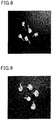
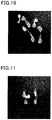
- Figs. 8 to 11 are pictures of pellets having an irregular shape.
- the pellets shown in Fig. 8 and Fig. 9 each have a whisker extending from the pellet body, so that the whole shape of each pellet is irregular.
- the whiskers may drop off the pellet bodies to be pellet scraps when the pellets are transferred from a hopper into a cylinder, possibly preventing formation of a coating layer having good wire diameter stability and capacitance stability.
- pellets shown in Fig. 10 two or more pieces of fluororesin having a usual pellet size are linked directly or via a whisker to form a mass, so that the whole shape of each pellet is irregular.
- Pellets having such a shape may prevent smooth transfer from a hopper into a cylinder, and the whiskers may drop off when the pellets are transferred, possibly preventing formation of a coating layer having good wire diameter stability and capacitance stability.
- the pellets shown in Fig. 11 have whiskers, burrs, projections, or other defects, and thus have rough edges, so that the whole shape of each pellet is irregular. Pellets having such a shape may prevent smooth transfer from a hopper into a cylinder, and the whiskers or burrs may drop off when the pellets are transferred, possibly preventing formation of a coating layer having good wire diameter stability and capacitance stability.
- the number of pellets having an irregular shape can be determined by randomly selecting 100 g of the pellets and visually counting the number of pellets having an irregular shape.
- the pellets may include pellets containing bubbles therein, but the weight proportion of such pellets is preferably 10 mass% or less for each 100 g of the pellets. Such pellets are not preferred because they may prevent formation of a coating layer having good wire diameter stability and capacitance stability.
- the number of pellets containing bubbles therein can be determined by randomly selecting 100 g of the pellets and visually counting the number of pellets containing bubbles therein.
- the pellets having an irregular shape can be reduced by feeding fluororesin powder stably into an extruder during production of the pellets using the extruder, for example.
- the present invention also relates to an electric wire including a core wire and a coating layer disposed around the core wire and formed from the pellets.
- the core wire may be formed from a metal conductive material such as copper or aluminum.
- the core wire preferably has a diameter of 0.02 to 3 mm.
- the diameter of the core wire is more preferably 0.04 mm or greater, still more preferably 0.05 mm or greater, particularly preferably 0.1 mm or greater.
- the diameter of the core wire is more preferably 2 mm or smaller.
- the coating layer of the electric wire preferably has a thickness of 0.1 to 3.0 mm.
- the thickness of the coating layer is also preferably 2.0 mm or smaller.
- the core wire examples include American wire gauge No. 46 (AWG-46) (solid copper wire having a diameter of 40 ⁇ m), AWG-26 (solid copper wire having a diameter of 404 ⁇ m), AWG-24 (solid copper wire having a diameter of 510 ⁇ m), and AWG-22 (solid copper wire having a diameter of 635 ⁇ m).
- AWG-46 solid copper wire having a diameter of 40 ⁇ m
- AWG-26 solid copper wire having a diameter of 404 ⁇ m
- AWG-24 solid copper wire having a diameter of 510 ⁇ m
- AWG-22 solid copper wire having a diameter of 635 ⁇ m.
- the coating layer may contain bubbles, and the bubbles are preferably distributed uniformly in the coating layer.
- the bubbles may have any average bubble diameter.
- the average bubble diameter is preferably 60 ⁇ m or smaller, more preferably 45 ⁇ m or smaller, still more preferably 35 pm or smaller, further more preferably 30 ⁇ m or smaller, particularly preferably 25 pm or smaller, still further more preferably 23 pm or smaller.
- the average bubble diameter is also preferably 0.1 pm or greater, more preferably 1 pm or greater.
- the average bubble diameter can be determined by taking an electron micrograph of the cross section of the electric wire, processing the image and calculating the diameter of each bubble, and averaging the diameters.
- the coating layer may have an expansion rate of 20% or higher.
- the expansion rate is more preferably 30% or higher, still more preferably 33% or higher, further more preferably 35% or higher.
- the upper limit thereof may be any value, and may be 80%, for example.
- the upper limit of the expansion rate may be 60%.
- the expansion rate is a value determined by ⁇ (specific gravity of fluororesin) - (specific gravity of coating layer) ⁇ /(specific gravity of fluororesin) ⁇ 100.
- the expansion rate can be adjusted as appropriate in accordance with the intended use by, for example, adjusting the amount of gas introduced in an extruder to be mentioned later or by selecting the type of gas to be dissolved.
- the electric wire may further include a different layer between the core wire and the coating layer, and may further include a different layer (outer layer) around the coating layer.
- the electric wire may have a bilayer structure (skin-foam) including a non-foamed layer between the core wire and the coating layer; a bilayer structure (foam-skin) including a non-foamed layer as an outer layer; or a trilayer structure (skin-foam-skin) including a non-foamed layer covering the outer layer of the above skin-foam structure.
- the non-foamed layer of the electric wire may be any layer, and may be a resin layer formed from resin such as a TFE/HFP copolymer, a TFE/PAVE copolymer, a TFE/ethylene copolymer, a vinylidene fluoride-based polymer, a polyolefin resin such as polyethylene (PE), or polyvinyl chloride (PVC).
- resin such as a TFE/HFP copolymer, a TFE/PAVE copolymer, a TFE/ethylene copolymer, a vinylidene fluoride-based polymer, a polyolefin resin such as polyethylene (PE), or polyvinyl chloride (PVC).
- the electric wire may be used as any of cables connecting a computer and its peripheral, such as a LAN cable.
- the electric wire may be produced by, for example, a method for producing an electric wire including a core wire and a coating layer using an extruder provided with a cylinder, a screw contained in the cylinder, a die attached to a tip of the cylinder, and a hopper configured to feed pellets into the cylinder, the method including preparing the pellets; pouring the pellets into the hopper; feeding the pellets from the hopper to the cylinder; melting the pellets in the cylinder to form a molten fluororesin; and extruding the molten fluororesin through the die to form the coating layer on the core wire.
- the coating layer containing bubbles can also be formed by introducing gas into the molten fluororesin inside the cylinder.
- the gas include chlorodifluoromethane, nitrogen, carbon dioxide, and mixtures of any of these gases.
- the gas may be introduced as pressurized gas into the molten fluororesin inside the extruder, or may be generated by mixing a chemical blowing agent into the molten fluororesin. The gas dissolves in the molten fluororesin inside the extruder.
- the material used was a dispersion obtained by emulsion polymerization with ammonium persulfate used as a polymerization initiator.
- TFE tetrafluoroethylene
- HFP hexafluoropropylene
- PPVE perfluoro(propyl vinyl ether)
- the die has a diameter of 2.5 mm and has four holes.
- the material was fed at a rate of 15 kg/h with a screw rotational frequency of 200 rpm.
- the temperature of the polymer extruded from the die was adjusted to 375°C.
- the rotational frequency of a double blade cutter was 2270 rpm. Thereby, polymer pellets were obtained.
- the polymer pellets were further brought into contact with 20 vol% fluorine gas diluted with nitrogen gas at 180°C for 24 hours.
- the MFR was determined using about 6 g of a sample and a melt index tester in conformity with ASTM D1238-98 or JIS K7210 with a die having a diameter of 2.1 mm and a length of 8 mm at 372°C and a 5-kg load (the sum of a piston and a weight).
- the melting point was determined from the corresponding peak of a heat-of-fusion curve obtained by thermal analysis at a temperature-increasing rate of 10°C/min using a differential scanning calorimeter RDC220 (Seiko Instruments Inc.) in conformity with ASTM D-4591.
- the pellets were rolled using a hydraulic press into a film having a thickness of about 0.3 mm, and this film was analyzed using FT-IR Spectrometer 1760 X (PerkinElmer).
- a difference spectrum from a standard sample (a sample sufficiently fluorinated to the extent that the spectra before and after the fluorination show substantially no difference) was obtained and the absorbance of each peak was read.
- correction coefficients (K) of the respective unstable end groups are as follows.
- 19 F-NMR was performed using a nuclear magnetic resonance device AC300 (Bruker BioSpin) at a measurement temperature of the melting point of the fluororesin + 20°C.
- the number of -CF 2 H end groups was determined from the integrated value of the peaks derived from the presence of -CF 2 H groups and the integrated value of the other peaks.
- the sum of the number of the unstable end groups and the number of -CF 2 H end groups is expressed as "the number of unstable end groups" in Tables 1 to 3.
- a hopper of an apparent density tester (standard JIS K6891 or 6892) was used. First, 300 g of the resulting pellets were fed into the hopper. The cover of outlet was pulled off, and the period of time until the pellets entirely flowed out was measured. The measurement was performed four times, and the average value thereof was calculated.
- the wire diameter stability and capacitance stability of an electric wire were evaluated.
- the core wire used (prepared by twisting together seven tin-plated copper wires having a diameter of 0.064 mm) had an outer diameter of 0.192 mm, and the outer diameter of the resulting electric wire was set to 0.312 mm.
- the temperature conditions were as follows: cylinder zone C1 (270°C); cylinder zone C2 (325°C); cylinder zone C3 (365°C); neck zone (375°C); head zone (385°C); die zone (390°C).
- the core-wire pre-heating temperature was set to 200°C.
- An electric wire was produced with a molten-cone length in molding of 20 mm, and the wire diameter stability and capacitance stability of the electric wire were evaluated.
- the wire diameter stability and the capacitance stability were evaluated as follows.
- the outer diameter (OD) was measured along 500 m of the electric wire at a drawing rate of 200 m/min using an outer diameter meter (LS-9006M, Keyence Corp.).
- the wire diameter stability was calculated as a process capability index (Cp).
- the Cp value was analyzed from the outer diameter data obtained using NR-500 and NR-HA08 (Keyence Corp.) with the upper limit (USL) set to 0.005 mm higher than the coated electric wire diameter (0.312 mm) and the lower limit (LSL) set to 0.005 mm lower than the coated electric wire diameter.
- the capacitance was measured for three hours using a capacitance measurement system CAPAC HS (ZUMBACH electronic AG), and the capacitance stability was calculated as a process capability index (Cp).
- the Cp value was analyzed from the outer diameter data obtained with the upper limit (USL) set to +1.0 (pF/m) and the lower limit (LSL) set to - 1.0 (pF/m).
- Pellets were obtained by the same procedure as in Example 1 except that the diameter of the die (die size), the number of die holes, the feed rate, the rotational frequency of the screw, the polymer temperature at the die outlet, and the rotational speed of the cutter blades in pelletization were changed as shown in Table 1, and the molding of electric wire coating was evaluated.
- Pellets were obtained by the same procedure as in Example 1 except that the amount of ammonium persulfate in emulsion polymerization was changed, and the molding of electric wire coating was evaluated.
- Pellets were obtained by the same procedure as in Example 1 except that the amount of ammonium persulfate in emulsion polymerization was changed.
- the molding of electric wire coating was evaluated in the same manner as in Example 1 except that the extrusion temperatures for molding of electric wire coating were changed as follows: cylinder zone C1 (280°C), cylinder zone C2 (335°C), cylinder zone C3 (375°C), neck zone (385°C), head zone (395°C), and die zone (400°C).
- Pellets were obtained by the same procedure as in Example 1 except that the fluororesin used contained a tetrafluoroethylene (TFE) unit and a hexafluoropropylene (HFP) unit and had a melting point of 256°C.
- the molding of electric wire coating was evaluated in the same manner as in Example 1 except that the extrusion temperatures for molding of electric wire coating were changed as follows: cylinder zone C1 (290°C), cylinder zone C2 (345°C), cylinder zone C3 (385°C), neck zone (395°C), head zone (405°C), and die zone (410°C).
- Pellets were obtained by the same procedure as in Example 8 except that the amount of ammonium persulfate in emulsion polymerization was changed.
- the molding of electric wire coating was evaluated in the same manner as in Example 1 except that the extrusion temperatures for molding of electric wire coating were changed as follows: cylinder zone C1 (280°C), cylinder zone C2 (335°C), cylinder zone C3 (375°C), neck zone (385°C), head zone (395°C), and die zone (400°C).
- TFE tetrafluoroethylene
- the molding of electric wire coating was evaluated in the same manner as in Example 1 except that the extrusion temperatures for molding of electric wire coating were changed as follows: cylinder zone C1 (280°C), cylinder zone C2 (335°C), cylinder zone C3 (375°C), neck zone (385°C), head zone (395°C), and die zone (400°C).
- Pellets were obtained by the same procedure as in Example 1 except that the diameter of the die (die size), the number of die holes, the feed rate, the rotational frequency of the screw, the polymer temperature at the die outlet, and the rotational speed of the cutter blades in pelletization were changed as shown in Table 2, and the molding of electric wire coating was evaluated in the same manner as in Example 1.
- Pellets were obtained under the pelletization conditions shown in Table 2 with the amount of ammonium persulfate in emulsion polymerization changed.
- the molding of electric wire coating was evaluated in the same manner as in Example 7.
- Pellets were obtained by the same procedure as in Example 8 except that the rotational speed of the cutter blades in pelletization was changed as shown in Table 2, and the molding of electric wire coating was evaluated.
- Pellets were obtained by the same procedure as in Example 9 except that the diameter of the die and the rotational speed of the cutter blades in pelletization were changed as shown in Table 2, and the molding of electric wire coating was evaluated.
- Example 10 Pellets were obtained by the same procedure as in Example 10 except that the rotational speed of the cutter blades in pelletization was changed as shown in Table 2, and the molding of electric wire coating was evaluated. [Table 1] Example 1 Example 2 Example 3 Example 4 Example 5 Example 6 Example 7 Example 8 Example 9 Example 10 Production conditions Melting point offluororesln °c 260 260 260 260 260 260 256 256 300 Pellet extrusion conditions Die size mm 2.5 2.1 1.5 2.5 2.5 2.5 2.5 2.5 2.5 2.5 2.5 2.5 2.5 2.5 2.5 2.5 2.5 2.5 2.5 2.5 2.5 2.5 2.5 2.5 2.5 2.5 2.5 2.5 2.5 2.5 2.5 Number of die holes - 4 7 20 4 4 4 4 4 4 Feed rate kg/hr 15 15 15 15 15 15 15 15 15 15 15 15 Rotational frequency of screw rpm 200 200 200 200 200 200 200 200 200 200 200 200 200 200 200 200 200 200 200 200 200 200 200 200 Polymer temperature at die outlet °c 375 375 375 375 375 375 375 375 375 375 375 375 375 375 375 375 375 375
- Example 11 Production conditions Melting point of fluororesin °C 260 Pellet extrusion conditions Die size mm 2.5 Number of die holes - 4 Feed rate kg/hr 15 Rotational frequency of screw rpm 200 Polymer temperature at die outlet °c 375 Rotational speed of cutter blades rpm 2270 Fluorination Not performed Physical properties of fluororesin Melting point °c 260 MFR g/10 min 36 Number of unstable end groups Groups 580 Evaluation of pellets Pellets Major axis D 1 mm 3.0 Minor axis D 2 mm 3.0 Height (thickness) L mm 1.4 (D 1 + D 2 )/2L - 2.2 Height (thickness) (deviation) mm 0.10 PCI pcs/100 g 2 Weight proportion of foamed pellets mass% 3 Result of pellet fluidity test sec 9.
Landscapes
- Engineering & Computer Science (AREA)
- Mechanical Engineering (AREA)
- Manufacturing & Machinery (AREA)
- Chemical & Material Sciences (AREA)
- Medicinal Chemistry (AREA)
- Health & Medical Sciences (AREA)
- Chemical Kinetics & Catalysis (AREA)
- Polymers & Plastics (AREA)
- Organic Chemistry (AREA)
- Spectroscopy & Molecular Physics (AREA)
- Physics & Mathematics (AREA)
- Processing And Handling Of Plastics And Other Materials For Molding In General (AREA)
- Extrusion Moulding Of Plastics Or The Like (AREA)
- Processes Specially Adapted For Manufacturing Cables (AREA)
- Treatments Of Macromolecular Shaped Articles (AREA)
- Manufacture Of Porous Articles, And Recovery And Treatment Of Waste Products (AREA)
- Processes Of Treating Macromolecular Substances (AREA)
- Insulated Conductors (AREA)
Claims (9)
- Pellets, umfassend ein Fluorharz,
wobei jedes der Pellets, wenn es auf einer horizontalen Oberfläche angeordnet ist, einen im Wesentlichen kreisförmigen Umriss (11) oder einen im Wesentlichen elliptischen Umriss (12) aufweist und eine Hauptachse D1 von 3,1 mm oder kürzer und eine Nebenachse D2 von 3,1 mm oder kürzer aufweist, wenn es in der Richtung senkrecht zur horizontalen Oberfläche betrachtet wird, dadurch gekennzeichnet, dass
die Hauptachse D1 1,6 mm oder länger ist und die Nebenachse D2 1,6 mm oder länger ist und die Pellets die folgende Formel (1) erfüllen:
- Pellets gemäß Anspruch 1,
wobei die Höhen L eine Standardabweichung von 0,3 mm oder kleiner aufweisen. - Pellets gemäß Anspruch 1 oder 2,
wobei die Pellets nicht mehr als 100 Pellets mit einer unregelmäßigen Form je 100 g der Pellets enthalten, und wobei die Anzahl der Pellets mit einer unregelmäßigen Form bestimmt wird, indem beliebige 100 g der Pellets ausgewählt werden und die Anzahl der unten aufgeführten Pellets durch visuelles Zählen bestimmt wird:
(a) Pellets mit einem Haarkristall ("whisker"); (b) Pellets, die aus zwei oder mehreren miteinander verbundenen Fluorharzstücken gebildet sind; und (c) Pellets mit einer unregelmäßigen Form. - Pellets gemäß einem der Ansprüche 1 bis 3,
wobei die Pellets 10 Massen-% oder weniger an Pellets enthalten, die Blasen enthalten, je 100 g der Pellets, und wobei der Gewichtsanteil der Pellets, die Blasen enthalten, wie folgt gemessen wird: 100 g der erhaltenen Pellets werden gewogen, Pellets, die Blasen enthalten, werden gesammelt und gewogen, und anschließend wird der Gewichtsanteil der Pellets, die Blasen enthalten, bestimmt. - Pellets gemäß einem der Ansprüche 1 bis 4,
wobei 300 g der Pellets innerhalb von 9,2 Sekunden in einem Pellet-Fluiditätstest ausgetragen werden, wobei der Pellet-Fluiditätstest wie folgt durchgeführt wird: 300 g Pellets werden in einen Trichter eines Schüttdichteprüfgeräts nach JIS K 6891 oder JIS K 6892 gegeben, der Deckel des Auslasses wird abgezogen und die Zeitspanne bis zum vollständigen Ausfließen der Pellets wird gemessen, wobei die Messung viermal durchgeführt wird und der Mittelwert davon berechnet wird. - Pellets gemäß einem der Ansprüche 1 bis 5,
wobei jedes Pellet eine im Wesentlichen kugelige Form, eine im Wesentlichen zylindrische Form oder eine im Wesentlichen elliptisch zylindrische Form aufweist. - Pellets gemäß einem der Ansprüche 1 bis 6,
wobei das Fluorharz insgesamt 120 oder weniger Gruppen, ausgewählt aus -COOH, -COOCH3, -CH2OH, -COF, -CONH2 und -CF2H, je 1 × 10⁶ Kohlenstoffatome enthält, wobei die Anzahl der Gruppen wie folgt bestimmt wird:(a) die Pellets werden mit einer hydraulischen Presse zu einem Film mit einer Dicke von etwa 0,3 mm gerollt, und dieser Film wird mit einem FT-IR-Spektrometer analysiert,
ein Differenzspektrum von einer wie in der Beschreibung beschriebenen Standardprobe wird erhalten und die Absorption von jedem Peak wird abgelesen, und die Anzahl der Gruppen je 1 × 10⁶ Kohlenstoffatome wird durch die folgende Formel berechnet:Anzahl der Gruppen je 1 × 10⁶ Kohlenstoffatome = (I × K)/twobei I für die Absorption steht, K für einen Korrekturkoeffizienten steht und t für eine Filmdicke in mm steht, unddie Korrekturkoeffizienten (K) der jeweiligen Gruppen wie folgt lauten:-COF (1884 cm-1): 405-COOH (1813 cm-1, 1775 cm-1): 455-COOCH3 (1795 cm-1): 355-CONH2 (3438 cm-1): 480-CH2OH (3648 cm-1): 2325(b) die Anzahl der -CF2H-Gruppen wird bestimmt, indem ein 19F-NMR bei einer Messtemperatur des Schmelzpunktes des Fluorharzes + 20°C gemessen wird, wobei die Anzahl der -CF2H-Gruppen aus dem integrierten Wert der Peaks, die sich von der Anwesenheit von -CF2H-Gruppen ableiten, und dem integrierten Wert der anderen Peaks bestimmt wird; und(c) die Summe der in (a) bestimmten Anzahl der Gruppen und der in (b) bestimmten Anzahl der -CF2H-Gruppen wird als Anzahl der Gruppen bestimmt. - Verwendung der wie in einem der Ansprüche 1 bis 7 definierten Pellets zur Bildung einer Überzugsschicht, die um einen Kerndraht eines elektrischen Drahtes angeordnet ist.
- Verfahren zur Herstellung eines elektrischen Drahts, der einen Kerndraht und eine Überzugsschicht enthält, unter Verwendung eines Extruders, der mit einem Zylinder, einer in dem Zylinder enthaltenen Schnecke, einer an einer Spitze des Zylinders angebrachten Düse und einem Trichter, der zur Zuführung von Pellets in den Zylinder konfiguriert ist, versehen ist, wobei das Verfahren umfasst:Herstellen der wie in einem der Ansprüche 1 bis 7 definierten Pellets;Gießen der Pellets in den Trichter;Zuführen der Pellets aus dem Trichter in den Zylinder;Schmelzen der Pellets in dem Zylinder, um ein geschmolzenes Fluorharz zu bilden; undExtrudieren des geschmolzenen Fluorharzes durch die Düse, um die Überzugsschicht auf dem Kerndraht zu bilden.
Priority Applications (1)
| Application Number | Priority Date | Filing Date | Title |
|---|---|---|---|
| EP21150203.4A EP3825087B1 (de) | 2016-01-18 | 2017-01-17 | Granulate enthaltend ein fluorharz, deren verwendung, sowie verfahren zur herstellung eines stromkabels damit |
Applications Claiming Priority (2)
| Application Number | Priority Date | Filing Date | Title |
|---|---|---|---|
| JP2016007360 | 2016-01-18 | ||
| PCT/JP2017/001404 WO2017126499A1 (ja) | 2016-01-18 | 2017-01-17 | フッ素樹脂のペレット、電線及びその製造方法 |
Related Child Applications (2)
| Application Number | Title | Priority Date | Filing Date |
|---|---|---|---|
| EP21150203.4A Division EP3825087B1 (de) | 2016-01-18 | 2017-01-17 | Granulate enthaltend ein fluorharz, deren verwendung, sowie verfahren zur herstellung eines stromkabels damit |
| EP21150203.4A Division-Into EP3825087B1 (de) | 2016-01-18 | 2017-01-17 | Granulate enthaltend ein fluorharz, deren verwendung, sowie verfahren zur herstellung eines stromkabels damit |
Publications (3)
| Publication Number | Publication Date |
|---|---|
| EP3378617A1 EP3378617A1 (de) | 2018-09-26 |
| EP3378617A4 EP3378617A4 (de) | 2019-07-24 |
| EP3378617B1 true EP3378617B1 (de) | 2021-02-24 |
Family
ID=59362713
Family Applications (2)
| Application Number | Title | Priority Date | Filing Date |
|---|---|---|---|
| EP21150203.4A Active EP3825087B1 (de) | 2016-01-18 | 2017-01-17 | Granulate enthaltend ein fluorharz, deren verwendung, sowie verfahren zur herstellung eines stromkabels damit |
| EP17741377.0A Active EP3378617B1 (de) | 2016-01-18 | 2017-01-17 | Granulate enthaltend ein fluorharz, deren verwendung sowie verfahren zur herstellung eines stromkabels damit |
Family Applications Before (1)
| Application Number | Title | Priority Date | Filing Date |
|---|---|---|---|
| EP21150203.4A Active EP3825087B1 (de) | 2016-01-18 | 2017-01-17 | Granulate enthaltend ein fluorharz, deren verwendung, sowie verfahren zur herstellung eines stromkabels damit |
Country Status (6)
| Country | Link |
|---|---|
| US (1) | US12122863B2 (de) |
| EP (2) | EP3825087B1 (de) |
| JP (1) | JP6213691B2 (de) |
| KR (1) | KR101867260B1 (de) |
| CN (2) | CN110437565B (de) |
| WO (1) | WO2017126499A1 (de) |
Families Citing this family (4)
| Publication number | Priority date | Publication date | Assignee | Title |
|---|---|---|---|---|
| JP2019051652A (ja) * | 2017-09-15 | 2019-04-04 | ダイキン工業株式会社 | 電線の製造方法 |
| JP7317668B2 (ja) | 2019-10-30 | 2023-07-31 | 住友化学株式会社 | 樹脂ペレット及び樹脂ペレットの製造方法 |
| KR20230045044A (ko) | 2020-08-03 | 2023-04-04 | 다이킨 고교 가부시키가이샤 | 발포 성형용 조성물, 발포 성형체, 전선, 발포 성형체의 제조 방법 및 전선의 제조 방법 |
| WO2024135735A1 (ja) | 2022-12-20 | 2024-06-27 | ダイキン工業株式会社 | 発泡成形用組成物、発泡成形体、発泡電線、発泡成形体の製造方法、電線の製造方法及び車載ネットワークケーブル |
Family Cites Families (17)
| Publication number | Priority date | Publication date | Assignee | Title |
|---|---|---|---|---|
| US4764538A (en) | 1987-12-16 | 1988-08-16 | E. I. Du Pont De Nemours And Company | Foam nucleation system for fluoropolymers |
| US5265507A (en) * | 1989-07-31 | 1993-11-30 | Kuraray Co., Ltd. | Process for producing pellets |
| JPH03233815A (ja) * | 1989-08-18 | 1991-10-17 | Fujikura Ltd | 発泡絶縁電線の製造方法 |
| ATE135488T1 (de) | 1989-08-18 | 1996-03-15 | Fujikura Ltd | Verfahren zur herstellung eines schaumisolierten elektrischen drahtes |
| JP2556149B2 (ja) | 1989-10-06 | 1996-11-20 | 日立電線株式会社 | 細径薄肉絶縁電線の製造方法 |
| US5688449A (en) * | 1995-10-02 | 1997-11-18 | Nitech Corporation | Method of forming and extruding an additive-coated resin composition |
| JP4068755B2 (ja) * | 1999-03-30 | 2008-03-26 | 帝人化成株式会社 | 熱可塑性樹脂組成物ペレットの製造方法及び該ペレットから成形された成形品 |
| JP2001113541A (ja) * | 1999-10-20 | 2001-04-24 | Yodogawa Kasei Kk | 回転成形用樹脂材料および回転成形方法 |
| JP4394362B2 (ja) * | 2003-03-11 | 2010-01-06 | 日本ポリプロ株式会社 | 樹脂ペレットの製造方法 |
| CN101163739B (zh) | 2005-05-18 | 2010-12-29 | 大金工业株式会社 | 氟树脂组合物和电线 |
| US9012580B2 (en) * | 2008-02-15 | 2015-04-21 | Daikin Industries, Ltd. | Tetrafluoroethylene/hexafluoropropylene copolymer and the production method thereof, and electrical wire |
| JP5418593B2 (ja) * | 2009-06-30 | 2014-02-19 | ダイキン工業株式会社 | 組成物及びその製造方法、並びに、粉体塗料、ペレット、樹脂成形品、及び電線 |
| CN103635517B (zh) * | 2011-07-05 | 2016-08-17 | 旭硝子株式会社 | 氟树脂颗粒的处理方法 |
| JP2014058625A (ja) | 2012-09-18 | 2014-04-03 | Hitachi Metals Ltd | 発泡樹脂成形体、発泡絶縁電線及びケーブル並びに発泡樹脂成形体の製造方法 |
| CN104955892B (zh) * | 2013-01-24 | 2019-03-12 | 大金工业株式会社 | 组合物以及发泡成型体和电线的制造方法 |
| WO2015053025A1 (ja) * | 2013-10-10 | 2015-04-16 | レジノカラー工業株式会社 | マスターバッチ、マスターバッチ群、マスターバッチの製造方法及び合成樹脂成形品 |
| KR101642575B1 (ko) * | 2014-07-04 | 2016-07-26 | 박현우 | 조사가교 불소고무 컴파운드를 이용한 절연전선 |
-
2017
- 2017-01-17 EP EP21150203.4A patent/EP3825087B1/de active Active
- 2017-01-17 CN CN201910812072.9A patent/CN110437565B/zh active Active
- 2017-01-17 KR KR1020187007202A patent/KR101867260B1/ko active Active
- 2017-01-17 CN CN201780003153.3A patent/CN108025456B/zh active Active
- 2017-01-17 US US16/061,512 patent/US12122863B2/en active Active
- 2017-01-17 JP JP2017005950A patent/JP6213691B2/ja active Active
- 2017-01-17 WO PCT/JP2017/001404 patent/WO2017126499A1/ja not_active Ceased
- 2017-01-17 EP EP17741377.0A patent/EP3378617B1/de active Active
Non-Patent Citations (1)
| Title |
|---|
| None * |
Also Published As
| Publication number | Publication date |
|---|---|
| EP3378617A4 (de) | 2019-07-24 |
| JP6213691B2 (ja) | 2017-10-18 |
| US20200262952A1 (en) | 2020-08-20 |
| CN110437565B (zh) | 2021-11-09 |
| WO2017126499A1 (ja) | 2017-07-27 |
| EP3825087B1 (de) | 2023-03-01 |
| CN108025456A (zh) | 2018-05-11 |
| CN110437565A (zh) | 2019-11-12 |
| KR20180031794A (ko) | 2018-03-28 |
| EP3378617A1 (de) | 2018-09-26 |
| CN108025456B (zh) | 2019-09-27 |
| KR101867260B1 (ko) | 2018-06-12 |
| JP2017128119A (ja) | 2017-07-27 |
| EP3825087A1 (de) | 2021-05-26 |
| US12122863B2 (en) | 2024-10-22 |
Similar Documents
| Publication | Publication Date | Title |
|---|---|---|
| EP2185648B1 (de) | Fluor-harz-zusammensetzung und isolierter elektrodraht | |
| EP2949701B1 (de) | Zusammensetzung und vorrichtung zur herstellung von schaumformmaterial und elektrischer draht | |
| CN105980426B (zh) | 四氟乙烯/六氟丙烯系共聚物和电线 | |
| EP2949700B1 (de) | Zusammensetzung und vorrichtung zur herstellung von schaumformmaterial und elektrischer draht | |
| JP2013126760A (ja) | 溶融ペレットの製造方法、及び、電線の製造方法 | |
| EP1887040A1 (de) | Fluorharzzusammensetzung und elektrischer draht | |
| EP3378617B1 (de) | Granulate enthaltend ein fluorharz, deren verwendung sowie verfahren zur herstellung eines stromkabels damit | |
| US20240268020A1 (en) | Composition, circuit board, and method for producing composition |
Legal Events
| Date | Code | Title | Description |
|---|---|---|---|
| STAA | Information on the status of an ep patent application or granted ep patent |
Free format text: STATUS: THE INTERNATIONAL PUBLICATION HAS BEEN MADE |
|
| PUAI | Public reference made under article 153(3) epc to a published international application that has entered the european phase |
Free format text: ORIGINAL CODE: 0009012 |
|
| STAA | Information on the status of an ep patent application or granted ep patent |
Free format text: STATUS: REQUEST FOR EXAMINATION WAS MADE |
|
| 17P | Request for examination filed |
Effective date: 20180618 |
|
| AK | Designated contracting states |
Kind code of ref document: A1 Designated state(s): AL AT BE BG CH CY CZ DE DK EE ES FI FR GB GR HR HU IE IS IT LI LT LU LV MC MK MT NL NO PL PT RO RS SE SI SK SM TR |
|
| AX | Request for extension of the european patent |
Extension state: BA ME |
|
| DAV | Request for validation of the european patent (deleted) | ||
| DAX | Request for extension of the european patent (deleted) | ||
| A4 | Supplementary search report drawn up and despatched |
Effective date: 20190626 |
|
| RIC1 | Information provided on ipc code assigned before grant |
Ipc: B29B 11/10 20060101ALI20190619BHEP Ipc: B29B 9/16 20060101AFI20190619BHEP Ipc: B29B 9/14 20060101ALN20190619BHEP Ipc: B29B 9/06 20060101ALN20190619BHEP Ipc: B29C 48/154 20190101ALI20190619BHEP Ipc: B29K 27/12 20060101ALN20190619BHEP Ipc: B29B 9/12 20060101ALI20190619BHEP Ipc: H01B 13/00 20060101ALI20190619BHEP |
|
| STAA | Information on the status of an ep patent application or granted ep patent |
Free format text: STATUS: EXAMINATION IS IN PROGRESS |
|
| 17Q | First examination report despatched |
Effective date: 20200428 |
|
| REG | Reference to a national code |
Ref country code: DE Ref legal event code: R079 Ref document number: 602017033288 Country of ref document: DE Free format text: PREVIOUS MAIN CLASS: B29B0009060000 Ipc: B29B0009160000 |
|
| RIC1 | Information provided on ipc code assigned before grant |
Ipc: B29B 9/12 20060101ALI20200803BHEP Ipc: B29B 9/16 20060101AFI20200803BHEP Ipc: H01B 13/14 20060101ALI20200803BHEP Ipc: B29B 9/06 20060101ALI20200803BHEP Ipc: B29C 48/34 20190101ALN20200803BHEP Ipc: B29B 9/14 20060101ALN20200803BHEP Ipc: B29C 48/154 20190101ALI20200803BHEP |
|
| GRAP | Despatch of communication of intention to grant a patent |
Free format text: ORIGINAL CODE: EPIDOSNIGR1 |
|
| STAA | Information on the status of an ep patent application or granted ep patent |
Free format text: STATUS: GRANT OF PATENT IS INTENDED |
|
| INTG | Intention to grant announced |
Effective date: 20201006 |
|
| GRAS | Grant fee paid |
Free format text: ORIGINAL CODE: EPIDOSNIGR3 |
|
| GRAA | (expected) grant |
Free format text: ORIGINAL CODE: 0009210 |
|
| STAA | Information on the status of an ep patent application or granted ep patent |
Free format text: STATUS: THE PATENT HAS BEEN GRANTED |
|
| AK | Designated contracting states |
Kind code of ref document: B1 Designated state(s): AL AT BE BG CH CY CZ DE DK EE ES FI FR GB GR HR HU IE IS IT LI LT LU LV MC MK MT NL NO PL PT RO RS SE SI SK SM TR |
|
| REG | Reference to a national code |
Ref country code: CH Ref legal event code: EP |
|
| REG | Reference to a national code |
Ref country code: DE Ref legal event code: R096 Ref document number: 602017033288 Country of ref document: DE |
|
| REG | Reference to a national code |
Ref country code: AT Ref legal event code: REF Ref document number: 1363883 Country of ref document: AT Kind code of ref document: T Effective date: 20210315 |
|
| REG | Reference to a national code |
Ref country code: IE Ref legal event code: FG4D |
|
| REG | Reference to a national code |
Ref country code: NL Ref legal event code: FP |
|
| REG | Reference to a national code |
Ref country code: LT Ref legal event code: MG9D |
|
| PG25 | Lapsed in a contracting state [announced via postgrant information from national office to epo] |
Ref country code: LT Free format text: LAPSE BECAUSE OF FAILURE TO SUBMIT A TRANSLATION OF THE DESCRIPTION OR TO PAY THE FEE WITHIN THE PRESCRIBED TIME-LIMIT Effective date: 20210224 Ref country code: BG Free format text: LAPSE BECAUSE OF FAILURE TO SUBMIT A TRANSLATION OF THE DESCRIPTION OR TO PAY THE FEE WITHIN THE PRESCRIBED TIME-LIMIT Effective date: 20210524 Ref country code: GR Free format text: LAPSE BECAUSE OF FAILURE TO SUBMIT A TRANSLATION OF THE DESCRIPTION OR TO PAY THE FEE WITHIN THE PRESCRIBED TIME-LIMIT Effective date: 20210525 Ref country code: HR Free format text: LAPSE BECAUSE OF FAILURE TO SUBMIT A TRANSLATION OF THE DESCRIPTION OR TO PAY THE FEE WITHIN THE PRESCRIBED TIME-LIMIT Effective date: 20210224 Ref country code: FI Free format text: LAPSE BECAUSE OF FAILURE TO SUBMIT A TRANSLATION OF THE DESCRIPTION OR TO PAY THE FEE WITHIN THE PRESCRIBED TIME-LIMIT Effective date: 20210224 Ref country code: PT Free format text: LAPSE BECAUSE OF FAILURE TO SUBMIT A TRANSLATION OF THE DESCRIPTION OR TO PAY THE FEE WITHIN THE PRESCRIBED TIME-LIMIT Effective date: 20210624 Ref country code: NO Free format text: LAPSE BECAUSE OF FAILURE TO SUBMIT A TRANSLATION OF THE DESCRIPTION OR TO PAY THE FEE WITHIN THE PRESCRIBED TIME-LIMIT Effective date: 20210524 |
|
| REG | Reference to a national code |
Ref country code: AT Ref legal event code: MK05 Ref document number: 1363883 Country of ref document: AT Kind code of ref document: T Effective date: 20210224 |
|
| PG25 | Lapsed in a contracting state [announced via postgrant information from national office to epo] |
Ref country code: RS Free format text: LAPSE BECAUSE OF FAILURE TO SUBMIT A TRANSLATION OF THE DESCRIPTION OR TO PAY THE FEE WITHIN THE PRESCRIBED TIME-LIMIT Effective date: 20210224 Ref country code: LV Free format text: LAPSE BECAUSE OF FAILURE TO SUBMIT A TRANSLATION OF THE DESCRIPTION OR TO PAY THE FEE WITHIN THE PRESCRIBED TIME-LIMIT Effective date: 20210224 Ref country code: PL Free format text: LAPSE BECAUSE OF FAILURE TO SUBMIT A TRANSLATION OF THE DESCRIPTION OR TO PAY THE FEE WITHIN THE PRESCRIBED TIME-LIMIT Effective date: 20210224 Ref country code: SE Free format text: LAPSE BECAUSE OF FAILURE TO SUBMIT A TRANSLATION OF THE DESCRIPTION OR TO PAY THE FEE WITHIN THE PRESCRIBED TIME-LIMIT Effective date: 20210224 |
|
| PG25 | Lapsed in a contracting state [announced via postgrant information from national office to epo] |
Ref country code: IS Free format text: LAPSE BECAUSE OF FAILURE TO SUBMIT A TRANSLATION OF THE DESCRIPTION OR TO PAY THE FEE WITHIN THE PRESCRIBED TIME-LIMIT Effective date: 20210624 |
|
| PG25 | Lapsed in a contracting state [announced via postgrant information from national office to epo] |
Ref country code: EE Free format text: LAPSE BECAUSE OF FAILURE TO SUBMIT A TRANSLATION OF THE DESCRIPTION OR TO PAY THE FEE WITHIN THE PRESCRIBED TIME-LIMIT Effective date: 20210224 Ref country code: CZ Free format text: LAPSE BECAUSE OF FAILURE TO SUBMIT A TRANSLATION OF THE DESCRIPTION OR TO PAY THE FEE WITHIN THE PRESCRIBED TIME-LIMIT Effective date: 20210224 Ref country code: SM Free format text: LAPSE BECAUSE OF FAILURE TO SUBMIT A TRANSLATION OF THE DESCRIPTION OR TO PAY THE FEE WITHIN THE PRESCRIBED TIME-LIMIT Effective date: 20210224 Ref country code: AT Free format text: LAPSE BECAUSE OF FAILURE TO SUBMIT A TRANSLATION OF THE DESCRIPTION OR TO PAY THE FEE WITHIN THE PRESCRIBED TIME-LIMIT Effective date: 20210224 |
|
| REG | Reference to a national code |
Ref country code: DE Ref legal event code: R097 Ref document number: 602017033288 Country of ref document: DE |
|
| PG25 | Lapsed in a contracting state [announced via postgrant information from national office to epo] |
Ref country code: RO Free format text: LAPSE BECAUSE OF FAILURE TO SUBMIT A TRANSLATION OF THE DESCRIPTION OR TO PAY THE FEE WITHIN THE PRESCRIBED TIME-LIMIT Effective date: 20210224 Ref country code: SK Free format text: LAPSE BECAUSE OF FAILURE TO SUBMIT A TRANSLATION OF THE DESCRIPTION OR TO PAY THE FEE WITHIN THE PRESCRIBED TIME-LIMIT Effective date: 20210224 Ref country code: DK Free format text: LAPSE BECAUSE OF FAILURE TO SUBMIT A TRANSLATION OF THE DESCRIPTION OR TO PAY THE FEE WITHIN THE PRESCRIBED TIME-LIMIT Effective date: 20210224 |
|
| PLBE | No opposition filed within time limit |
Free format text: ORIGINAL CODE: 0009261 |
|
| STAA | Information on the status of an ep patent application or granted ep patent |
Free format text: STATUS: NO OPPOSITION FILED WITHIN TIME LIMIT |
|
| PG25 | Lapsed in a contracting state [announced via postgrant information from national office to epo] |
Ref country code: ES Free format text: LAPSE BECAUSE OF FAILURE TO SUBMIT A TRANSLATION OF THE DESCRIPTION OR TO PAY THE FEE WITHIN THE PRESCRIBED TIME-LIMIT Effective date: 20210224 Ref country code: AL Free format text: LAPSE BECAUSE OF FAILURE TO SUBMIT A TRANSLATION OF THE DESCRIPTION OR TO PAY THE FEE WITHIN THE PRESCRIBED TIME-LIMIT Effective date: 20210224 |
|
| 26N | No opposition filed |
Effective date: 20211125 |
|
| PG25 | Lapsed in a contracting state [announced via postgrant information from national office to epo] |
Ref country code: SI Free format text: LAPSE BECAUSE OF FAILURE TO SUBMIT A TRANSLATION OF THE DESCRIPTION OR TO PAY THE FEE WITHIN THE PRESCRIBED TIME-LIMIT Effective date: 20210224 |
|
| PG25 | Lapsed in a contracting state [announced via postgrant information from national office to epo] |
Ref country code: IS Free format text: LAPSE BECAUSE OF FAILURE TO SUBMIT A TRANSLATION OF THE DESCRIPTION OR TO PAY THE FEE WITHIN THE PRESCRIBED TIME-LIMIT Effective date: 20210624 |
|
| PG25 | Lapsed in a contracting state [announced via postgrant information from national office to epo] |
Ref country code: MC Free format text: LAPSE BECAUSE OF FAILURE TO SUBMIT A TRANSLATION OF THE DESCRIPTION OR TO PAY THE FEE WITHIN THE PRESCRIBED TIME-LIMIT Effective date: 20210224 |
|
| REG | Reference to a national code |
Ref country code: CH Ref legal event code: PL |
|
| REG | Reference to a national code |
Ref country code: BE Ref legal event code: MM Effective date: 20220131 |
|
| PG25 | Lapsed in a contracting state [announced via postgrant information from national office to epo] |
Ref country code: LU Free format text: LAPSE BECAUSE OF NON-PAYMENT OF DUE FEES Effective date: 20220117 |
|
| PG25 | Lapsed in a contracting state [announced via postgrant information from national office to epo] |
Ref country code: BE Free format text: LAPSE BECAUSE OF NON-PAYMENT OF DUE FEES Effective date: 20220131 |
|
| PG25 | Lapsed in a contracting state [announced via postgrant information from national office to epo] |
Ref country code: LI Free format text: LAPSE BECAUSE OF NON-PAYMENT OF DUE FEES Effective date: 20220131 Ref country code: CH Free format text: LAPSE BECAUSE OF NON-PAYMENT OF DUE FEES Effective date: 20220131 |
|
| PG25 | Lapsed in a contracting state [announced via postgrant information from national office to epo] |
Ref country code: IE Free format text: LAPSE BECAUSE OF NON-PAYMENT OF DUE FEES Effective date: 20220117 |
|
| P01 | Opt-out of the competence of the unified patent court (upc) registered |
Effective date: 20230525 |
|
| PG25 | Lapsed in a contracting state [announced via postgrant information from national office to epo] |
Ref country code: HU Free format text: LAPSE BECAUSE OF FAILURE TO SUBMIT A TRANSLATION OF THE DESCRIPTION OR TO PAY THE FEE WITHIN THE PRESCRIBED TIME-LIMIT; INVALID AB INITIO Effective date: 20170117 |
|
| PG25 | Lapsed in a contracting state [announced via postgrant information from national office to epo] |
Ref country code: MK Free format text: LAPSE BECAUSE OF FAILURE TO SUBMIT A TRANSLATION OF THE DESCRIPTION OR TO PAY THE FEE WITHIN THE PRESCRIBED TIME-LIMIT Effective date: 20210224 Ref country code: CY Free format text: LAPSE BECAUSE OF FAILURE TO SUBMIT A TRANSLATION OF THE DESCRIPTION OR TO PAY THE FEE WITHIN THE PRESCRIBED TIME-LIMIT Effective date: 20210224 |
|
| PG25 | Lapsed in a contracting state [announced via postgrant information from national office to epo] |
Ref country code: MT Free format text: LAPSE BECAUSE OF FAILURE TO SUBMIT A TRANSLATION OF THE DESCRIPTION OR TO PAY THE FEE WITHIN THE PRESCRIBED TIME-LIMIT Effective date: 20210224 |
|
| PGFP | Annual fee paid to national office [announced via postgrant information from national office to epo] |
Ref country code: NL Payment date: 20241213 Year of fee payment: 9 |
|
| PGFP | Annual fee paid to national office [announced via postgrant information from national office to epo] |
Ref country code: GB Payment date: 20241128 Year of fee payment: 9 |
|
| PGFP | Annual fee paid to national office [announced via postgrant information from national office to epo] |
Ref country code: FR Payment date: 20241209 Year of fee payment: 9 |
|
| PGFP | Annual fee paid to national office [announced via postgrant information from national office to epo] |
Ref country code: DE Payment date: 20241203 Year of fee payment: 9 |
|
| PGFP | Annual fee paid to national office [announced via postgrant information from national office to epo] |
Ref country code: IT Payment date: 20241210 Year of fee payment: 9 |
|
| PG25 | Lapsed in a contracting state [announced via postgrant information from national office to epo] |
Ref country code: TR Free format text: LAPSE BECAUSE OF FAILURE TO SUBMIT A TRANSLATION OF THE DESCRIPTION OR TO PAY THE FEE WITHIN THE PRESCRIBED TIME-LIMIT Effective date: 20210224 |