EP3377716B1 - Dispositif de structure déployable d'abri - Google Patents
Dispositif de structure déployable d'abri Download PDFInfo
- Publication number
- EP3377716B1 EP3377716B1 EP16812985.6A EP16812985A EP3377716B1 EP 3377716 B1 EP3377716 B1 EP 3377716B1 EP 16812985 A EP16812985 A EP 16812985A EP 3377716 B1 EP3377716 B1 EP 3377716B1
- Authority
- EP
- European Patent Office
- Prior art keywords
- arm
- structure device
- adjustable
- arms
- uprights
- Prior art date
- Legal status (The legal status is an assumption and is not a legal conclusion. Google has not performed a legal analysis and makes no representation as to the accuracy of the status listed.)
- Active
Links
Images


Classifications
-
- E—FIXED CONSTRUCTIONS
- E04—BUILDING
- E04H—BUILDINGS OR LIKE STRUCTURES FOR PARTICULAR PURPOSES; SWIMMING OR SPLASH BATHS OR POOLS; MASTS; FENCING; TENTS OR CANOPIES, IN GENERAL
- E04H15/00—Tents or canopies, in general
- E04H15/32—Parts, components, construction details, accessories, interior equipment, specially adapted for tents, e.g. guy-line equipment, skirts, thresholds
- E04H15/34—Supporting means, e.g. frames
- E04H15/44—Supporting means, e.g. frames collapsible, e.g. breakdown type
- E04H15/48—Supporting means, e.g. frames collapsible, e.g. breakdown type foldable, i.e. having pivoted or hinged means
- E04H15/50—Supporting means, e.g. frames collapsible, e.g. breakdown type foldable, i.e. having pivoted or hinged means lazy-tongs type
-
- E—FIXED CONSTRUCTIONS
- E04—BUILDING
- E04H—BUILDINGS OR LIKE STRUCTURES FOR PARTICULAR PURPOSES; SWIMMING OR SPLASH BATHS OR POOLS; MASTS; FENCING; TENTS OR CANOPIES, IN GENERAL
- E04H15/00—Tents or canopies, in general
- E04H15/32—Parts, components, construction details, accessories, interior equipment, specially adapted for tents, e.g. guy-line equipment, skirts, thresholds
- E04H15/34—Supporting means, e.g. frames
- E04H15/44—Supporting means, e.g. frames collapsible, e.g. breakdown type
- E04H15/46—Supporting means, e.g. frames collapsible, e.g. breakdown type telescoping and foldable
-
- E—FIXED CONSTRUCTIONS
- E04—BUILDING
- E04H—BUILDINGS OR LIKE STRUCTURES FOR PARTICULAR PURPOSES; SWIMMING OR SPLASH BATHS OR POOLS; MASTS; FENCING; TENTS OR CANOPIES, IN GENERAL
- E04H15/00—Tents or canopies, in general
- E04H15/32—Parts, components, construction details, accessories, interior equipment, specially adapted for tents, e.g. guy-line equipment, skirts, thresholds
- E04H15/58—Closures; Awnings; Sunshades
-
- G—PHYSICS
- G01—MEASURING; TESTING
- G01S—RADIO DIRECTION-FINDING; RADIO NAVIGATION; DETERMINING DISTANCE OR VELOCITY BY USE OF RADIO WAVES; LOCATING OR PRESENCE-DETECTING BY USE OF THE REFLECTION OR RERADIATION OF RADIO WAVES; ANALOGOUS ARRANGEMENTS USING OTHER WAVES
- G01S17/00—Systems using the reflection or reradiation of electromagnetic waves other than radio waves, e.g. lidar systems
- G01S17/86—Combinations of lidar systems with systems other than lidar, radar or sonar, e.g. with direction finders
-
- G—PHYSICS
- G01—MEASURING; TESTING
- G01S—RADIO DIRECTION-FINDING; RADIO NAVIGATION; DETERMINING DISTANCE OR VELOCITY BY USE OF RADIO WAVES; LOCATING OR PRESENCE-DETECTING BY USE OF THE REFLECTION OR RERADIATION OF RADIO WAVES; ANALOGOUS ARRANGEMENTS USING OTHER WAVES
- G01S17/00—Systems using the reflection or reradiation of electromagnetic waves other than radio waves, e.g. lidar systems
- G01S17/88—Lidar systems specially adapted for specific applications
- G01S17/89—Lidar systems specially adapted for specific applications for mapping or imaging
-
- G—PHYSICS
- G01—MEASURING; TESTING
- G01S—RADIO DIRECTION-FINDING; RADIO NAVIGATION; DETERMINING DISTANCE OR VELOCITY BY USE OF RADIO WAVES; LOCATING OR PRESENCE-DETECTING BY USE OF THE REFLECTION OR RERADIATION OF RADIO WAVES; ANALOGOUS ARRANGEMENTS USING OTHER WAVES
- G01S17/00—Systems using the reflection or reradiation of electromagnetic waves other than radio waves, e.g. lidar systems
- G01S17/88—Lidar systems specially adapted for specific applications
- G01S17/93—Lidar systems specially adapted for specific applications for anti-collision purposes
- G01S17/933—Lidar systems specially adapted for specific applications for anti-collision purposes of aircraft or spacecraft
-
- G—PHYSICS
- G01—MEASURING; TESTING
- G01S—RADIO DIRECTION-FINDING; RADIO NAVIGATION; DETERMINING DISTANCE OR VELOCITY BY USE OF RADIO WAVES; LOCATING OR PRESENCE-DETECTING BY USE OF THE REFLECTION OR RERADIATION OF RADIO WAVES; ANALOGOUS ARRANGEMENTS USING OTHER WAVES
- G01S7/00—Details of systems according to groups G01S13/00, G01S15/00, G01S17/00
- G01S7/48—Details of systems according to groups G01S13/00, G01S15/00, G01S17/00 of systems according to group G01S17/00
- G01S7/481—Constructional features, e.g. arrangements of optical elements
- G01S7/4811—Constructional features, e.g. arrangements of optical elements common to transmitter and receiver
- G01S7/4813—Housing arrangements
-
- G—PHYSICS
- G05—CONTROLLING; REGULATING
- G05D—SYSTEMS FOR CONTROLLING OR REGULATING NON-ELECTRIC VARIABLES
- G05D1/00—Control of position, course, altitude or attitude of land, water, air or space vehicles, e.g. using automatic pilots
- G05D1/10—Simultaneous control of position or course in three dimensions
- G05D1/101—Simultaneous control of position or course in three dimensions specially adapted for aircraft
- G05D1/102—Simultaneous control of position or course in three dimensions specially adapted for aircraft specially adapted for vertical take-off of aircraft
-
- G—PHYSICS
- G01—MEASURING; TESTING
- G01S—RADIO DIRECTION-FINDING; RADIO NAVIGATION; DETERMINING DISTANCE OR VELOCITY BY USE OF RADIO WAVES; LOCATING OR PRESENCE-DETECTING BY USE OF THE REFLECTION OR RERADIATION OF RADIO WAVES; ANALOGOUS ARRANGEMENTS USING OTHER WAVES
- G01S13/00—Systems using the reflection or reradiation of radio waves, e.g. radar systems; Analogous systems using reflection or reradiation of waves whose nature or wavelength is irrelevant or unspecified
- G01S13/88—Radar or analogous systems specially adapted for specific applications
- G01S13/93—Radar or analogous systems specially adapted for specific applications for anti-collision purposes
- G01S13/933—Radar or analogous systems specially adapted for specific applications for anti-collision purposes of aircraft or spacecraft
- G01S13/935—Radar or analogous systems specially adapted for specific applications for anti-collision purposes of aircraft or spacecraft for terrain-avoidance
Definitions
- the present invention is in the field of deployable structure devices intended to serve as shelter or tent.
- Such a shelter is generally made of a metal structure covered at least in the upper part by a covering element forming a roof, such as a tarpaulin. Said structure is provided deployable, allowing the shelter to pass from a folded position, for storage and transport, to an extended position forming a shelter, and vice versa. In the deployed position, the shelter generally has a polyhedral shape, preferably rectangular parallelepiped surmounted by the covering element.
- a shelter structure comprising a plurality of telescopic uprights, each having a plurality of sections slidably mounted longitudinally vertically relative to one another.
- These amounts support at their upper portion a skeleton forming a mesh and composed, in the longitudinal direction, of several spars movably connected together, on the one hand, along their length, in particular their center, through joints of chisel type and, secondly, at their ends through pivoting articulation, giving the assembly a global pantograph shape, which can fold and unfold in the manner of an accordion.
- the ends of some longitudinal members are connected to the upper sections of the uprights through pivot points.
- some pivot points of the ends of the longitudinal members slide along the upper portions of the corresponding amounts.
- the skeleton has a similar frame, in braces, connecting sleepers, with a similar deformable geometry.
- the skeleton has a specific shape, with inner boxes, shaped in deformable polyhedra, in particular parallelograms, especially with diamond faces and triangles.
- This skeleton has at least one symmetry along a vertical axis orthogonal to the longitudinal direction of the structure, then allowing the passage of the folded position where the amounts are brought closer to each other, to the deployed position of the shelter, and vice versa, by deformation of said boxes.
- Such shelters with simple slope remain limited in number, in particular because of their limited use and their impossibility to be refolded optimally. Indeed, such shelters have an asymmetrical structure, raised to the front. This elevation leads to an inclination of the skeleton and its asymmetry making the folding of the shelter impossible or complex, through tedious manipulations, to obtain a folded structure within a volume of larger size compared to a conventional shelter. Shelters with simple slope are then often constituted by a removable and non-collapsible structure. In addition, the slope of the roof of such a shelter is determined according to the length of the side members, making it impossible to change its degree of inclination.
- the invention specifically relates to a shelter whose covering element has a single slope, extending in a decreasing manner, from the front to the rear of the shelter or vice versa, or even from one side to the other.
- a shelter has a skeleton shaped pantograph.
- the purpose of the invention is to propose a shelter allowing, from a structure with a skeleton shaped as a pantograph allowing the unfolding and folding of the shelter, to obtain an inclination of the slope of the cover element.
- the degree of this slope can be modified according to the implantation, or even the climatic conditions.
- each spar having an adjustable length, preferably at least two, from an elongated position to a shortened position, and vice versa, through intermediate positions.
- the longitudinally adjustable aspect of each spar is provided telescopically, by sliding segments constituting the spars and adapted means which they are equipped.
- each spar deforms the geometry of the entire structure, tilting each amount to which it is connected. Because of the telescopic nature of each amount, it is then possible to increase or decrease its height and thus rectify its inclination relative to the vertical, to straighten the entire structure and raise one of its sides, conferring the desired single slope to the roof. By operating inversely, it is possible to return to a classical form of structure, allowing confined folding within the same space as a classical structure.
- the subject of the invention is a deployable shelter structure device, comprising uprights supporting in the upper part a deformable skeleton comprising mobile spars consisting of at least one pair of scissors-articulated arms connected through points of contact. pivoting to uprights whose pivot point, connecting to the upper end of the upright the end of an arm being fixed, while the other lower pivot point being located lower and slidably mounted along said upright slidably connecting this end to the end of the other arm.
- Such a device is characterized in that at least one arm of a pair of arms of the longitudinal members is provided longitudinally adjustable through means of lengthening and shortening of its length.
- At least one arm is longitudinally adjustable at a first end of a spar and at least one arm, depending on the case of the same pair or not, at the opposite end of this spar is also adjustable longitudinally through means of elongation and shortening.
- said elongation and shortening means may be telescopic, through sliding segments constituting each adjustable arm.
- Said elongation and shortening means may comprise means for indexing the length of each adjustable arm to the levels of elongated and shortened end positions, or even in intermediate positions.
- each adjustable arm may comprise a sheath, on the one hand, slidably mounted externally relative to a main segment of said adjustable arm and, on the other hand, secured to a pivot point (or point of articulation) at the level of an amount.
- Said sleeve can be secured to the pivot point through a distal segment attached to one end of said sleeve and rotatably mounted through said pivot point (or a point of rotation).
- Said indexing means may be fixedly mounted on said sheath and may comprise a lug cooperating by insertion through orifices arranged vis-a-vis and along said main segment.
- At least two amounts can be provided telescopic, to adjust their length and straighten the structure.
- the present invention relates to a structural device 1 intended to serve as shelter or tent.
- Said structure 1 comprises uprights 2 supporting in the upper part a skeleton 3.
- the structure 1 is intended to receive a cover covering element 4, then forming the roof. Therefore, the cover thus covered has a generally polyhedral shape.
- the shelter is rectangular in shape and has four uprights 2.
- the shelter may have another shape, including hexagonal or octagonal base, then having a greater number of amounts 2.
- Said device 1 is provided deployable, capable of passing from a folded position to an extended position, and vice versa.
- the skeleton 3 is provided deformable. In particular, it consists of elements articulated together, allowing a deformation of the geometry of the entire structure 1, to move from a folded position to the deployed position, through intermediate positions, and vice versa .
- said skeleton 3 comprises movable spars 5.
- the skeleton 3 may include sleepers 50 provided also movable, articulated similarly to the longitudinal members 5, to form a transverse reinforcement braces.
- a spar 5 consists of at least one pair of arms 5a, 5b, articulated in scissors.
- these arms 5a, 5b are connected substantially in their middle through a hinge 6 with horizontal or substantially horizontal axis of rotation.
- the mobility of the spars 5 is obtained through scissor joints 6 of his or her pairs of arms.
- a spar 5 may consist of a succession of such pairs of arms 5a, 5b articulated in a chisel. At least one end of each arm 5a; 5b of a first pair is connected to the concordant end of an arm 5b; 5a of the following pair, this by means of pivoting joints 7, in particular in the form of a rod 70.
- the mobility of the beams 5 is obtained at least with the uprights 2 through pivot points 8; 80 with the arms 5a, 5b.
- This junction is made at the opposite ends of the longitudinal members 5.
- the pivot point 8 located at the upper end of the upright 2 and connecting thereto the end of the arm, as appropriate, 5b or 5a, is fixed.
- another lower pivot point 80 is located lower and is slidably mounted along said upright 2. This lower pivot point 80 therefore slidably connects to this upright 2 the end of the arm, as the case may be, 5a or 5b.
- the arms 5a are connected through the lower pivot points 80 on these uprights 2 and slide vertically, ensuring the deformation of the Skeleton 3 for a good folding of the whole.
- the translation in sliding can be carried out in particular by means of a carriage on which is mounted the lower pivoting point 80, said carriage sliding within a rail, in particular constituted by a slide formed within said amount 2.
- This carriage can be locked relative to the upright 2 in several positions, especially in the up position when the structure is deployed.
- the skeleton 3 may comprise crosspieces 50 provided also movable and formed of one or more pairs of arms 5c, 5d articulated in a chisel manner similar to those of the longitudinal members 5.
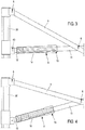
- the mobility of the longitudinal members 5 can also be obtained with these crosspieces 50 at the points of articulation 800. More particularly at such a point of articulation 800, an end of one of the arms 5c, 5d of a pair corresponding to a crosspiece 50, is cooperating, in an articulated manner, in a substantially perpendicular direction and through a suitable connecting piece, in particular in the form of a cross, with one end of one arm, as the case 5a , 5b, of a pair of arms of a spar 5, forming a cross mesh. This configuration is visible on the figure 1 .
- the structure 1 makes it possible to obtain an inclination of the covering element 4.
- the degree of the slope obtained can be adjusted, in particular according to predefined angles.
- At least one of the arms 5a, 5b of a pair of arms of a spar 5 is provided longitudinally adjustable through means 9 of elongation and shortening of its length.
- an arm of a spar 5 can be elongated or shortened, inducing a change in the shape of the structure 1, conferring asymmetry with respect to a transverse vertical median plane.
- At least one arm 5a is longitudinally adjustable at a first end 60 of a spar 5 and at least one arm 5b, as the case may be of the same pair or not, at the opposite end 61 of this spar 5 is also adjustable longitudinally.
- This adjustment in length of the adjustable arms 5a, 5b can be obtained through means 9 adapted elongation and shortening.
- At least each spar 5 located at the lateral ends of the structure 1 comprise arms 5a, 5b provided with means 9 of elongation and shortening.
- the elongation of the arms 5b at the end 61 of the longitudinal members 5 induced inclination amounts 2b side of the same end 61. While a shortening of the arms 5a on the side of the first end 60 of the side members 5 induces a tilting of the amount 2a in the same direction. In order to straighten the amounts 2a and 2b, it is necessary, essentially, to extend the amounts 2a to the left of the structure 1. This results in the slope of the cover element 4.
- each amount 2 can be advantageously provided deployable.
- each upright 2 can be provided telescopically.
- an amount 2 comprises at least two sections 20, inside and outside, sliding relative to each other to move from a retracted position during the folding of the structure 1, to a deployed position during deployment of said structure 1 and vice versa.
- each arm 5a, 5b of a spar 5 equipped with means 9 is preferably located on either side, at the ends of the skeleton 3, along the longitudinal edges of the structure 1. Therefore, the means 9 connect the arms, as the case 5a or 5b, the uprights 2 at the lower pivot points 80, as well as at the hinge points 800 of the arms 5c, 5d of the cross members 50 of the crossbeam.
- the means 9 make it possible to increase or decrease the length at the end equipped with the adjustable arms 5a, 5b.
- said elongation and shortening means 9 are telescopic, through sliding segments constituting each adjustable arm 5a, 5b.
- each adjustable arm 5a, 5b comprise at a distal end 12 a sleeve 10, on the one hand, slidably mounted externally relative to a main segment 11 of said adjustable arm 5a, 5b and, secondly, secured to a pivot point 80 or a point of articulation 800.
- this sleeve 10 is secured at one of its ends to the pivot point 80 (or a point of articulation 800).
- said lengthening and shortening means 9 comprise means 13 indexing the length of each adjustable arm 5a, 5b at positions, preferably but not exclusively, extreme elongated and shortened, or advantageously also in intermediate positions.
- said lengthening and shortening means 9 comprise means 13 indexing the length of each adjustable arm 5a, 5b at positions, preferably but not exclusively, extreme elongated and shortened, or advantageously also in intermediate positions.
- all means 9 may not be equipped with indexing.
- only the means 9 secured to the uprights 2 have indexing means 13, while the others, connected to the transverse frame provided crosspieces 50 in crosspieces, do not necessarily have, optionally being able to slide freely. Therefore, only the means 9 connected to the uprights 2 are used for indexing and locking.
- said indexing means 13 are fixedly mounted at the opposite end of said sheath 10, in particular via a piece secured around the sheath 10. They comprise a lug 14 cooperating with insertion through openings 15 formed vis-à-vis and along said main segment 11. This lug 14 is mounted in translation within a complementarily shaped housing.
- the lug 14 may also be provided with elastic return means, the pushing in a translational movement to an insertion position and locking.
- gripping means 16 adapted, then to slide the main segment of the adjustable arm 5a, 5b relative to the sheath 10 until a hole 15 is found opposite said lug 14 and that the latter comes to be pushed automatically to engage.
- Each orifice 15 then makes it possible to adjust a particular position and inclination of the slope of the device 1.
- the orifices 15 may be spaced at regular intervals or not.
- indexing means 13 may take various embodiments intended to immobilize in a given position the length of an adjustable arm 5a, 5b, such as pin, spring leaf with ball, screw nut system, etc. ...
- the displacement of the sections 20 of each upright 2 can also be indexed to block vertically in several positions, preferably a low position where the sections 20 are fully retracted, an extreme position of maximum deployment in which the frame is raised, but also at least an intermediate position in which the frame is horizontal.
- the indexing of the positions along the uprights 2 may advantageously correspond to the indexing of the means 9 at the level of the orifices 15.
- the angle of the slope may be indexed according to determined angular values, ranging from 1 to 45 degrees, preferably at least 5 degrees, in intervals of 1 to 5 degrees.
- the structure device 1 makes it possible quickly and simply to give a slope to a shelter, from a skeleton 3 shaped in pantographs, as well as braces, by means of the elongation and the shortening of certain adjustable arms 5a, 5b of its longitudinal members 5, while retaining the geometry necessary for optimum folding of such a structure 1.
- variable length of at least one spar 5, preferably several allows the deformation of the parallelograms of the skeleton 3, conferring on the latter, as the case may be, a regularity necessary for the folding of said structure 1 or, unlike, after deployment, an irregularity to print on the roof inclination desired. From this inclination and the telescopic nature of the or uprights 2, follows the inclination, with respect to the horizontal, of the roof, in a direction of said structure 1, preferably the longitudinal direction.
- the invention can be adapted to the levels of crosspieces and the transverse mesh in crosspieces, in order to impart an inclination in the transverse direction of the structure 1.
Landscapes
- Engineering & Computer Science (AREA)
- Architecture (AREA)
- Physics & Mathematics (AREA)
- Remote Sensing (AREA)
- Radar, Positioning & Navigation (AREA)
- General Physics & Mathematics (AREA)
- Structural Engineering (AREA)
- Civil Engineering (AREA)
- Computer Networks & Wireless Communication (AREA)
- Electromagnetism (AREA)
- Aviation & Aerospace Engineering (AREA)
- Automation & Control Theory (AREA)
- Tents Or Canopies (AREA)
Applications Claiming Priority (3)
| Application Number | Priority Date | Filing Date | Title |
|---|---|---|---|
| FR1561007A FR3043710A1 (fr) | 2015-11-16 | 2015-11-16 | Structure deployable a toit a une pente |
| FR1654227A FR3043709B1 (fr) | 2015-11-16 | 2016-05-12 | Structure deployable a toit a une pente |
| PCT/FR2016/052965 WO2017085398A1 (fr) | 2015-11-16 | 2016-11-16 | Dispositif de structure deployable d'abri |
Publications (2)
| Publication Number | Publication Date |
|---|---|
| EP3377716A1 EP3377716A1 (fr) | 2018-09-26 |
| EP3377716B1 true EP3377716B1 (fr) | 2019-08-07 |
Family
ID=70738241
Family Applications (1)
| Application Number | Title | Priority Date | Filing Date |
|---|---|---|---|
| EP16812985.6A Active EP3377716B1 (fr) | 2015-11-16 | 2016-11-16 | Dispositif de structure déployable d'abri |
Country Status (5)
| Country | Link |
|---|---|
| US (1) | US10662667B2 (enExample) |
| EP (1) | EP3377716B1 (enExample) |
| JP (1) | JP6949303B2 (enExample) |
| FR (1) | FR3043709B1 (enExample) |
| WO (1) | WO2017085398A1 (enExample) |
Families Citing this family (4)
| Publication number | Priority date | Publication date | Assignee | Title |
|---|---|---|---|---|
| US11220835B2 (en) | 2019-10-08 | 2022-01-11 | Shelterlogic Corp. | Pop-up canopy |
| US11889828B2 (en) | 2020-04-06 | 2024-02-06 | Jeremiah Banfield | Hunting blind |
| CN111762331B (zh) * | 2020-06-09 | 2021-10-15 | 福建通图信息技术有限公司 | 一种无人机防护用对拉型遮护装置 |
| CN114876276B (zh) * | 2022-03-29 | 2023-11-14 | 中国铁建重工集团股份有限公司 | 一种天幕工作装置 |
Family Cites Families (18)
| Publication number | Priority date | Publication date | Assignee | Title |
|---|---|---|---|---|
| JPS53133409U (enExample) * | 1977-03-29 | 1978-10-23 | ||
| US4607656A (en) * | 1983-09-26 | 1986-08-26 | Carter Mark C | Quick erection collapsible shelter |
| US5085398A (en) * | 1988-10-19 | 1992-02-04 | Holcomb Grove R | Adjustable form brace |
| FI86796C (fi) * | 1990-02-13 | 1992-10-26 | Ahlstroem Oy | Anordning foer lutning av liggunderlag i sjukhussaeng |
| JPH0514433U (ja) * | 1991-08-06 | 1993-02-26 | 有限会社井口商店 | 蛇腹式膜体構造物 |
| US6206020B1 (en) * | 1998-08-14 | 2001-03-27 | James P. Lynch | Collapsible canopy framework and structure with articulating scissor assemblies |
| US6141934A (en) * | 1998-12-07 | 2000-11-07 | World Shelters, Inc. | Folding frame system with foldable leg assembly and method of erecting a folding frame system |
| KR100365016B1 (ko) * | 1999-10-09 | 2002-12-16 | 주식회사 이드림텍 | 절첩식 텐트 |
| US6772780B2 (en) * | 2002-03-04 | 2004-08-10 | Roy Justin Price | Collapsible frame |
| AT6563U1 (de) * | 2002-12-23 | 2003-12-29 | Expotrade Group Handelsges M B | Zelt |
| US7533498B2 (en) * | 2004-02-18 | 2009-05-19 | World Shelters, Inc. | Mechanically deployable expandable and collapsible structure and method for deploying a structure |
| DE102004053669A1 (de) * | 2004-11-03 | 2006-05-04 | Röder Zelt- und Veranstaltungsservice GmbH | Zelt mit variabler Form |
| FR2893653B1 (fr) * | 2005-11-18 | 2008-01-11 | Vitabri Sa | Montant telescopique pour structure pliable et telle structure |
| US8662096B2 (en) * | 2007-02-27 | 2014-03-04 | Vitabri, Societe Anonyme | Folding structure that can be unfolded and refolded quickly |
| FR2913043B1 (fr) * | 2007-02-27 | 2010-11-12 | Vitabri | Structure pliable a developpement et repliement rapide. |
| WO2010006344A1 (en) * | 2008-06-11 | 2010-01-14 | Sunsmart Products (Pty) Ltd | Collapsible self-supporting fabric shelter |
| US7703469B2 (en) * | 2008-06-13 | 2010-04-27 | Paxdanz, Llc | Portable adjustable shade structure |
| KR20130096950A (ko) * | 2012-02-23 | 2013-09-02 | 신재기 | 접철식 캐노피 프레임 및 이를 이용한 캐노피 |
-
2016
- 2016-05-12 FR FR1654227A patent/FR3043709B1/fr not_active Expired - Fee Related
- 2016-11-16 US US15/776,665 patent/US10662667B2/en active Active
- 2016-11-16 JP JP2018525381A patent/JP6949303B2/ja active Active
- 2016-11-16 EP EP16812985.6A patent/EP3377716B1/fr active Active
- 2016-11-16 WO PCT/FR2016/052965 patent/WO2017085398A1/fr not_active Ceased
Non-Patent Citations (1)
| Title |
|---|
| None * |
Also Published As
| Publication number | Publication date |
|---|---|
| US20180328073A1 (en) | 2018-11-15 |
| FR3043709B1 (fr) | 2019-11-08 |
| JP6949303B2 (ja) | 2021-10-13 |
| EP3377716A1 (fr) | 2018-09-26 |
| US10662667B2 (en) | 2020-05-26 |
| FR3043709A1 (fr) | 2017-05-19 |
| JP2019500519A (ja) | 2019-01-10 |
| WO2017085398A1 (fr) | 2017-05-26 |
Similar Documents
| Publication | Publication Date | Title |
|---|---|---|
| EP3377716B1 (fr) | Dispositif de structure déployable d'abri | |
| AT5165U1 (de) | Freiarmschirm | |
| EP0433195A1 (fr) | Mur d'escalade artificiel transportable | |
| WO2008104645A1 (fr) | Structure pliable a deploiement et repliement rapides | |
| US20100230208A1 (en) | Convertible multipurpose ladder stabilizers | |
| FR2557909A1 (fr) | Abri leger en forme de tente. | |
| EP1948889B1 (fr) | Montant telescopique pour structure pliable et telle structure | |
| CA2414173A1 (fr) | Grue avec fleche articulee | |
| EP3011119B1 (fr) | Dispositif d'aménagement d'abri démontable et/ou pliable | |
| EP2806097A1 (fr) | Marchepied muni de roues escamotables, dont une roue avant montée basculante avec commande manuelle | |
| EP2078819A1 (fr) | Escabeau avec plateforme rabattable et jambes d'appui écartables | |
| EP3030731B1 (fr) | Dispositif de structure de couverture exterieure d'un abri | |
| CA2720809A1 (fr) | Dispositif permettant de reduire la prise au vent de la toile de protection d'un parasol ou autre abri | |
| FR2987354A1 (fr) | Dispositif de structure depliable et repliable de type mat telescopique | |
| FR3043710A1 (fr) | Structure deployable a toit a une pente | |
| EP0300939A2 (fr) | Dispositif de déploiement et escamotage en faux-plafond d'une literie ou similaire | |
| DE10003663C2 (de) | Zusammenlegbarer und transportabler Freizeitstuhl | |
| EP2725141A2 (fr) | Membre articulé comportant un outil de traitement de parois et véhicule de traitement de parois d'un ouvrage | |
| FR2672925A1 (fr) | Abri leger repliable. | |
| FR3049973A1 (fr) | Abri, notamment pergola bioclimatique, a modularite de luminosite perfectionnee | |
| WO1998004796A1 (fr) | Abri pliable equipe de poutres articulees a parallelogrammes deformables | |
| WO2013076123A1 (fr) | Tribune télescopique, motorisée, déplaçable | |
| EP3743660A1 (fr) | Structure de cadres articules déployables sur des rails | |
| FR2634701A1 (fr) | Plate-forme roulante de transport, de montage et de demontage d'une structure de couverture deployable | |
| FR3035570A3 (fr) | Modele de pare-soleil |
Legal Events
| Date | Code | Title | Description |
|---|---|---|---|
| STAA | Information on the status of an ep patent application or granted ep patent |
Free format text: STATUS: UNKNOWN |
|
| STAA | Information on the status of an ep patent application or granted ep patent |
Free format text: STATUS: THE INTERNATIONAL PUBLICATION HAS BEEN MADE |
|
| PUAI | Public reference made under article 153(3) epc to a published international application that has entered the european phase |
Free format text: ORIGINAL CODE: 0009012 |
|
| STAA | Information on the status of an ep patent application or granted ep patent |
Free format text: STATUS: REQUEST FOR EXAMINATION WAS MADE |
|
| 17P | Request for examination filed |
Effective date: 20180419 |
|
| AK | Designated contracting states |
Kind code of ref document: A1 Designated state(s): AL AT BE BG CH CY CZ DE DK EE ES FI FR GB GR HR HU IE IS IT LI LT LU LV MC MK MT NL NO PL PT RO RS SE SI SK SM TR |
|
| AX | Request for extension of the european patent |
Extension state: BA ME |
|
| DAV | Request for validation of the european patent (deleted) | ||
| DAX | Request for extension of the european patent (deleted) | ||
| GRAP | Despatch of communication of intention to grant a patent |
Free format text: ORIGINAL CODE: EPIDOSNIGR1 |
|
| STAA | Information on the status of an ep patent application or granted ep patent |
Free format text: STATUS: GRANT OF PATENT IS INTENDED |
|
| INTG | Intention to grant announced |
Effective date: 20190416 |
|
| GRAS | Grant fee paid |
Free format text: ORIGINAL CODE: EPIDOSNIGR3 |
|
| GRAA | (expected) grant |
Free format text: ORIGINAL CODE: 0009210 |
|
| STAA | Information on the status of an ep patent application or granted ep patent |
Free format text: STATUS: THE PATENT HAS BEEN GRANTED |
|
| AK | Designated contracting states |
Kind code of ref document: B1 Designated state(s): AL AT BE BG CH CY CZ DE DK EE ES FI FR GB GR HR HU IE IS IT LI LT LU LV MC MK MT NL NO PL PT RO RS SE SI SK SM TR |
|
| REG | Reference to a national code |
Ref country code: GB Ref legal event code: FG4D Free format text: NOT ENGLISH |
|
| REG | Reference to a national code |
Ref country code: CH Ref legal event code: EP Ref country code: AT Ref legal event code: REF Ref document number: 1164121 Country of ref document: AT Kind code of ref document: T Effective date: 20190815 |
|
| REG | Reference to a national code |
Ref country code: DE Ref legal event code: R096 Ref document number: 602016018367 Country of ref document: DE |
|
| REG | Reference to a national code |
Ref country code: IE Ref legal event code: FG4D Free format text: LANGUAGE OF EP DOCUMENT: FRENCH |
|
| REG | Reference to a national code |
Ref country code: NL Ref legal event code: MP Effective date: 20190807 |
|
| REG | Reference to a national code |
Ref country code: LT Ref legal event code: MG4D |
|
| PG25 | Lapsed in a contracting state [announced via postgrant information from national office to epo] |
Ref country code: FI Free format text: LAPSE BECAUSE OF FAILURE TO SUBMIT A TRANSLATION OF THE DESCRIPTION OR TO PAY THE FEE WITHIN THE PRESCRIBED TIME-LIMIT Effective date: 20190807 Ref country code: LT Free format text: LAPSE BECAUSE OF FAILURE TO SUBMIT A TRANSLATION OF THE DESCRIPTION OR TO PAY THE FEE WITHIN THE PRESCRIBED TIME-LIMIT Effective date: 20190807 Ref country code: HR Free format text: LAPSE BECAUSE OF FAILURE TO SUBMIT A TRANSLATION OF THE DESCRIPTION OR TO PAY THE FEE WITHIN THE PRESCRIBED TIME-LIMIT Effective date: 20190807 Ref country code: NL Free format text: LAPSE BECAUSE OF FAILURE TO SUBMIT A TRANSLATION OF THE DESCRIPTION OR TO PAY THE FEE WITHIN THE PRESCRIBED TIME-LIMIT Effective date: 20190807 Ref country code: NO Free format text: LAPSE BECAUSE OF FAILURE TO SUBMIT A TRANSLATION OF THE DESCRIPTION OR TO PAY THE FEE WITHIN THE PRESCRIBED TIME-LIMIT Effective date: 20191107 Ref country code: BG Free format text: LAPSE BECAUSE OF FAILURE TO SUBMIT A TRANSLATION OF THE DESCRIPTION OR TO PAY THE FEE WITHIN THE PRESCRIBED TIME-LIMIT Effective date: 20191107 Ref country code: PT Free format text: LAPSE BECAUSE OF FAILURE TO SUBMIT A TRANSLATION OF THE DESCRIPTION OR TO PAY THE FEE WITHIN THE PRESCRIBED TIME-LIMIT Effective date: 20191209 Ref country code: SE Free format text: LAPSE BECAUSE OF FAILURE TO SUBMIT A TRANSLATION OF THE DESCRIPTION OR TO PAY THE FEE WITHIN THE PRESCRIBED TIME-LIMIT Effective date: 20190807 |
|
| REG | Reference to a national code |
Ref country code: AT Ref legal event code: MK05 Ref document number: 1164121 Country of ref document: AT Kind code of ref document: T Effective date: 20190807 |
|
| PG25 | Lapsed in a contracting state [announced via postgrant information from national office to epo] |
Ref country code: IS Free format text: LAPSE BECAUSE OF FAILURE TO SUBMIT A TRANSLATION OF THE DESCRIPTION OR TO PAY THE FEE WITHIN THE PRESCRIBED TIME-LIMIT Effective date: 20191207 Ref country code: ES Free format text: LAPSE BECAUSE OF FAILURE TO SUBMIT A TRANSLATION OF THE DESCRIPTION OR TO PAY THE FEE WITHIN THE PRESCRIBED TIME-LIMIT Effective date: 20190807 Ref country code: GR Free format text: LAPSE BECAUSE OF FAILURE TO SUBMIT A TRANSLATION OF THE DESCRIPTION OR TO PAY THE FEE WITHIN THE PRESCRIBED TIME-LIMIT Effective date: 20191108 Ref country code: RS Free format text: LAPSE BECAUSE OF FAILURE TO SUBMIT A TRANSLATION OF THE DESCRIPTION OR TO PAY THE FEE WITHIN THE PRESCRIBED TIME-LIMIT Effective date: 20190807 Ref country code: LV Free format text: LAPSE BECAUSE OF FAILURE TO SUBMIT A TRANSLATION OF THE DESCRIPTION OR TO PAY THE FEE WITHIN THE PRESCRIBED TIME-LIMIT Effective date: 20190807 Ref country code: AL Free format text: LAPSE BECAUSE OF FAILURE TO SUBMIT A TRANSLATION OF THE DESCRIPTION OR TO PAY THE FEE WITHIN THE PRESCRIBED TIME-LIMIT Effective date: 20190807 |
|
| PG25 | Lapsed in a contracting state [announced via postgrant information from national office to epo] |
Ref country code: TR Free format text: LAPSE BECAUSE OF FAILURE TO SUBMIT A TRANSLATION OF THE DESCRIPTION OR TO PAY THE FEE WITHIN THE PRESCRIBED TIME-LIMIT Effective date: 20190807 |
|
| PG25 | Lapsed in a contracting state [announced via postgrant information from national office to epo] |
Ref country code: IT Free format text: LAPSE BECAUSE OF FAILURE TO SUBMIT A TRANSLATION OF THE DESCRIPTION OR TO PAY THE FEE WITHIN THE PRESCRIBED TIME-LIMIT Effective date: 20190807 Ref country code: RO Free format text: LAPSE BECAUSE OF FAILURE TO SUBMIT A TRANSLATION OF THE DESCRIPTION OR TO PAY THE FEE WITHIN THE PRESCRIBED TIME-LIMIT Effective date: 20190807 Ref country code: DK Free format text: LAPSE BECAUSE OF FAILURE TO SUBMIT A TRANSLATION OF THE DESCRIPTION OR TO PAY THE FEE WITHIN THE PRESCRIBED TIME-LIMIT Effective date: 20190807 Ref country code: EE Free format text: LAPSE BECAUSE OF FAILURE TO SUBMIT A TRANSLATION OF THE DESCRIPTION OR TO PAY THE FEE WITHIN THE PRESCRIBED TIME-LIMIT Effective date: 20190807 Ref country code: AT Free format text: LAPSE BECAUSE OF FAILURE TO SUBMIT A TRANSLATION OF THE DESCRIPTION OR TO PAY THE FEE WITHIN THE PRESCRIBED TIME-LIMIT Effective date: 20190807 Ref country code: PL Free format text: LAPSE BECAUSE OF FAILURE TO SUBMIT A TRANSLATION OF THE DESCRIPTION OR TO PAY THE FEE WITHIN THE PRESCRIBED TIME-LIMIT Effective date: 20190807 |
|
| PG25 | Lapsed in a contracting state [announced via postgrant information from national office to epo] |
Ref country code: SM Free format text: LAPSE BECAUSE OF FAILURE TO SUBMIT A TRANSLATION OF THE DESCRIPTION OR TO PAY THE FEE WITHIN THE PRESCRIBED TIME-LIMIT Effective date: 20190807 Ref country code: SK Free format text: LAPSE BECAUSE OF FAILURE TO SUBMIT A TRANSLATION OF THE DESCRIPTION OR TO PAY THE FEE WITHIN THE PRESCRIBED TIME-LIMIT Effective date: 20190807 Ref country code: IS Free format text: LAPSE BECAUSE OF FAILURE TO SUBMIT A TRANSLATION OF THE DESCRIPTION OR TO PAY THE FEE WITHIN THE PRESCRIBED TIME-LIMIT Effective date: 20200224 Ref country code: CZ Free format text: LAPSE BECAUSE OF FAILURE TO SUBMIT A TRANSLATION OF THE DESCRIPTION OR TO PAY THE FEE WITHIN THE PRESCRIBED TIME-LIMIT Effective date: 20190807 |
|
| REG | Reference to a national code |
Ref country code: DE Ref legal event code: R097 Ref document number: 602016018367 Country of ref document: DE |
|
| PLBE | No opposition filed within time limit |
Free format text: ORIGINAL CODE: 0009261 |
|
| STAA | Information on the status of an ep patent application or granted ep patent |
Free format text: STATUS: NO OPPOSITION FILED WITHIN TIME LIMIT |
|
| PG2D | Information on lapse in contracting state deleted |
Ref country code: IS |
|
| PG25 | Lapsed in a contracting state [announced via postgrant information from national office to epo] |
Ref country code: MC Free format text: LAPSE BECAUSE OF FAILURE TO SUBMIT A TRANSLATION OF THE DESCRIPTION OR TO PAY THE FEE WITHIN THE PRESCRIBED TIME-LIMIT Effective date: 20190807 Ref country code: LU Free format text: LAPSE BECAUSE OF NON-PAYMENT OF DUE FEES Effective date: 20191116 |
|
| 26N | No opposition filed |
Effective date: 20200603 |
|
| PG25 | Lapsed in a contracting state [announced via postgrant information from national office to epo] |
Ref country code: SI Free format text: LAPSE BECAUSE OF FAILURE TO SUBMIT A TRANSLATION OF THE DESCRIPTION OR TO PAY THE FEE WITHIN THE PRESCRIBED TIME-LIMIT Effective date: 20190807 |
|
| PG25 | Lapsed in a contracting state [announced via postgrant information from national office to epo] |
Ref country code: IE Free format text: LAPSE BECAUSE OF NON-PAYMENT OF DUE FEES Effective date: 20191116 |
|
| PG25 | Lapsed in a contracting state [announced via postgrant information from national office to epo] |
Ref country code: CY Free format text: LAPSE BECAUSE OF FAILURE TO SUBMIT A TRANSLATION OF THE DESCRIPTION OR TO PAY THE FEE WITHIN THE PRESCRIBED TIME-LIMIT Effective date: 20190807 |
|
| PG25 | Lapsed in a contracting state [announced via postgrant information from national office to epo] |
Ref country code: HU Free format text: LAPSE BECAUSE OF FAILURE TO SUBMIT A TRANSLATION OF THE DESCRIPTION OR TO PAY THE FEE WITHIN THE PRESCRIBED TIME-LIMIT; INVALID AB INITIO Effective date: 20161116 Ref country code: MT Free format text: LAPSE BECAUSE OF FAILURE TO SUBMIT A TRANSLATION OF THE DESCRIPTION OR TO PAY THE FEE WITHIN THE PRESCRIBED TIME-LIMIT Effective date: 20190807 |
|
| PG25 | Lapsed in a contracting state [announced via postgrant information from national office to epo] |
Ref country code: MK Free format text: LAPSE BECAUSE OF FAILURE TO SUBMIT A TRANSLATION OF THE DESCRIPTION OR TO PAY THE FEE WITHIN THE PRESCRIBED TIME-LIMIT Effective date: 20190807 |
|
| PGFP | Annual fee paid to national office [announced via postgrant information from national office to epo] |
Ref country code: DE Payment date: 20241206 Year of fee payment: 9 |
|
| PGFP | Annual fee paid to national office [announced via postgrant information from national office to epo] |
Ref country code: BE Payment date: 20241126 Year of fee payment: 9 |
|
| PGFP | Annual fee paid to national office [announced via postgrant information from national office to epo] |
Ref country code: GB Payment date: 20241127 Year of fee payment: 9 |
|
| PGFP | Annual fee paid to national office [announced via postgrant information from national office to epo] |
Ref country code: FR Payment date: 20241125 Year of fee payment: 9 |
|
| PGFP | Annual fee paid to national office [announced via postgrant information from national office to epo] |
Ref country code: CH Payment date: 20241201 Year of fee payment: 9 |
|
| REG | Reference to a national code |
Ref country code: CH Ref legal event code: U11 Free format text: ST27 STATUS EVENT CODE: U-0-0-U10-U11 (AS PROVIDED BY THE NATIONAL OFFICE) Effective date: 20251201 |