EP3377716B1 - Dispositif de structure déployable d'abri - Google Patents
Dispositif de structure déployable d'abri Download PDFInfo
- Publication number
- EP3377716B1 EP3377716B1 EP16812985.6A EP16812985A EP3377716B1 EP 3377716 B1 EP3377716 B1 EP 3377716B1 EP 16812985 A EP16812985 A EP 16812985A EP 3377716 B1 EP3377716 B1 EP 3377716B1
- Authority
- EP
- European Patent Office
- Prior art keywords
- arm
- structure device
- adjustable
- arms
- uprights
- Prior art date
- Legal status (The legal status is an assumption and is not a legal conclusion. Google has not performed a legal analysis and makes no representation as to the accuracy of the status listed.)
- Active
Links
- 238000004904 shortening Methods 0.000 claims description 22
- 238000003780 insertion Methods 0.000 claims description 4
- 230000037431 insertion Effects 0.000 claims description 4
- 230000003247 decreasing effect Effects 0.000 description 3
- 229910003460 diamond Inorganic materials 0.000 description 1
- 239000010432 diamond Substances 0.000 description 1
- 238000006073 displacement reaction Methods 0.000 description 1
- 238000002513 implantation Methods 0.000 description 1
- 230000001939 inductive effect Effects 0.000 description 1
- 239000002184 metal Substances 0.000 description 1
- 230000002787 reinforcement Effects 0.000 description 1
Images


Classifications
-
- E—FIXED CONSTRUCTIONS
- E04—BUILDING
- E04H—BUILDINGS OR LIKE STRUCTURES FOR PARTICULAR PURPOSES; SWIMMING OR SPLASH BATHS OR POOLS; MASTS; FENCING; TENTS OR CANOPIES, IN GENERAL
- E04H15/00—Tents or canopies, in general
- E04H15/32—Parts, components, construction details, accessories, interior equipment, specially adapted for tents, e.g. guy-line equipment, skirts, thresholds
- E04H15/34—Supporting means, e.g. frames
- E04H15/44—Supporting means, e.g. frames collapsible, e.g. breakdown type
- E04H15/48—Supporting means, e.g. frames collapsible, e.g. breakdown type foldable, i.e. having pivoted or hinged means
- E04H15/50—Supporting means, e.g. frames collapsible, e.g. breakdown type foldable, i.e. having pivoted or hinged means lazy-tongs type
-
- E—FIXED CONSTRUCTIONS
- E04—BUILDING
- E04H—BUILDINGS OR LIKE STRUCTURES FOR PARTICULAR PURPOSES; SWIMMING OR SPLASH BATHS OR POOLS; MASTS; FENCING; TENTS OR CANOPIES, IN GENERAL
- E04H15/00—Tents or canopies, in general
- E04H15/32—Parts, components, construction details, accessories, interior equipment, specially adapted for tents, e.g. guy-line equipment, skirts, thresholds
- E04H15/34—Supporting means, e.g. frames
- E04H15/44—Supporting means, e.g. frames collapsible, e.g. breakdown type
- E04H15/46—Supporting means, e.g. frames collapsible, e.g. breakdown type telescoping and foldable
-
- E—FIXED CONSTRUCTIONS
- E04—BUILDING
- E04H—BUILDINGS OR LIKE STRUCTURES FOR PARTICULAR PURPOSES; SWIMMING OR SPLASH BATHS OR POOLS; MASTS; FENCING; TENTS OR CANOPIES, IN GENERAL
- E04H15/00—Tents or canopies, in general
- E04H15/32—Parts, components, construction details, accessories, interior equipment, specially adapted for tents, e.g. guy-line equipment, skirts, thresholds
- E04H15/58—Closures; Awnings; Sunshades
-
- G—PHYSICS
- G01—MEASURING; TESTING
- G01S—RADIO DIRECTION-FINDING; RADIO NAVIGATION; DETERMINING DISTANCE OR VELOCITY BY USE OF RADIO WAVES; LOCATING OR PRESENCE-DETECTING BY USE OF THE REFLECTION OR RERADIATION OF RADIO WAVES; ANALOGOUS ARRANGEMENTS USING OTHER WAVES
- G01S17/00—Systems using the reflection or reradiation of electromagnetic waves other than radio waves, e.g. lidar systems
- G01S17/86—Combinations of lidar systems with systems other than lidar, radar or sonar, e.g. with direction finders
-
- G—PHYSICS
- G01—MEASURING; TESTING
- G01S—RADIO DIRECTION-FINDING; RADIO NAVIGATION; DETERMINING DISTANCE OR VELOCITY BY USE OF RADIO WAVES; LOCATING OR PRESENCE-DETECTING BY USE OF THE REFLECTION OR RERADIATION OF RADIO WAVES; ANALOGOUS ARRANGEMENTS USING OTHER WAVES
- G01S17/00—Systems using the reflection or reradiation of electromagnetic waves other than radio waves, e.g. lidar systems
- G01S17/88—Lidar systems specially adapted for specific applications
- G01S17/89—Lidar systems specially adapted for specific applications for mapping or imaging
-
- G—PHYSICS
- G01—MEASURING; TESTING
- G01S—RADIO DIRECTION-FINDING; RADIO NAVIGATION; DETERMINING DISTANCE OR VELOCITY BY USE OF RADIO WAVES; LOCATING OR PRESENCE-DETECTING BY USE OF THE REFLECTION OR RERADIATION OF RADIO WAVES; ANALOGOUS ARRANGEMENTS USING OTHER WAVES
- G01S17/00—Systems using the reflection or reradiation of electromagnetic waves other than radio waves, e.g. lidar systems
- G01S17/88—Lidar systems specially adapted for specific applications
- G01S17/93—Lidar systems specially adapted for specific applications for anti-collision purposes
- G01S17/933—Lidar systems specially adapted for specific applications for anti-collision purposes of aircraft or spacecraft
-
- G—PHYSICS
- G01—MEASURING; TESTING
- G01S—RADIO DIRECTION-FINDING; RADIO NAVIGATION; DETERMINING DISTANCE OR VELOCITY BY USE OF RADIO WAVES; LOCATING OR PRESENCE-DETECTING BY USE OF THE REFLECTION OR RERADIATION OF RADIO WAVES; ANALOGOUS ARRANGEMENTS USING OTHER WAVES
- G01S7/00—Details of systems according to groups G01S13/00, G01S15/00, G01S17/00
- G01S7/48—Details of systems according to groups G01S13/00, G01S15/00, G01S17/00 of systems according to group G01S17/00
- G01S7/481—Constructional features, e.g. arrangements of optical elements
- G01S7/4811—Constructional features, e.g. arrangements of optical elements common to transmitter and receiver
- G01S7/4813—Housing arrangements
-
- G—PHYSICS
- G05—CONTROLLING; REGULATING
- G05D—SYSTEMS FOR CONTROLLING OR REGULATING NON-ELECTRIC VARIABLES
- G05D1/00—Control of position, course, altitude or attitude of land, water, air or space vehicles, e.g. using automatic pilots
- G05D1/10—Simultaneous control of position or course in three dimensions
- G05D1/101—Simultaneous control of position or course in three dimensions specially adapted for aircraft
- G05D1/102—Simultaneous control of position or course in three dimensions specially adapted for aircraft specially adapted for vertical take-off of aircraft
-
- G—PHYSICS
- G01—MEASURING; TESTING
- G01S—RADIO DIRECTION-FINDING; RADIO NAVIGATION; DETERMINING DISTANCE OR VELOCITY BY USE OF RADIO WAVES; LOCATING OR PRESENCE-DETECTING BY USE OF THE REFLECTION OR RERADIATION OF RADIO WAVES; ANALOGOUS ARRANGEMENTS USING OTHER WAVES
- G01S13/00—Systems using the reflection or reradiation of radio waves, e.g. radar systems; Analogous systems using reflection or reradiation of waves whose nature or wavelength is irrelevant or unspecified
- G01S13/88—Radar or analogous systems specially adapted for specific applications
- G01S13/93—Radar or analogous systems specially adapted for specific applications for anti-collision purposes
- G01S13/933—Radar or analogous systems specially adapted for specific applications for anti-collision purposes of aircraft or spacecraft
- G01S13/935—Radar or analogous systems specially adapted for specific applications for anti-collision purposes of aircraft or spacecraft for terrain-avoidance
Definitions
- the present invention is in the field of deployable structure devices intended to serve as shelter or tent.
- Such a shelter is generally made of a metal structure covered at least in the upper part by a covering element forming a roof, such as a tarpaulin. Said structure is provided deployable, allowing the shelter to pass from a folded position, for storage and transport, to an extended position forming a shelter, and vice versa. In the deployed position, the shelter generally has a polyhedral shape, preferably rectangular parallelepiped surmounted by the covering element.
- a shelter structure comprising a plurality of telescopic uprights, each having a plurality of sections slidably mounted longitudinally vertically relative to one another.
- These amounts support at their upper portion a skeleton forming a mesh and composed, in the longitudinal direction, of several spars movably connected together, on the one hand, along their length, in particular their center, through joints of chisel type and, secondly, at their ends through pivoting articulation, giving the assembly a global pantograph shape, which can fold and unfold in the manner of an accordion.
- the ends of some longitudinal members are connected to the upper sections of the uprights through pivot points.
- some pivot points of the ends of the longitudinal members slide along the upper portions of the corresponding amounts.
- the skeleton has a similar frame, in braces, connecting sleepers, with a similar deformable geometry.
- the skeleton has a specific shape, with inner boxes, shaped in deformable polyhedra, in particular parallelograms, especially with diamond faces and triangles.
- This skeleton has at least one symmetry along a vertical axis orthogonal to the longitudinal direction of the structure, then allowing the passage of the folded position where the amounts are brought closer to each other, to the deployed position of the shelter, and vice versa, by deformation of said boxes.
- Such shelters with simple slope remain limited in number, in particular because of their limited use and their impossibility to be refolded optimally. Indeed, such shelters have an asymmetrical structure, raised to the front. This elevation leads to an inclination of the skeleton and its asymmetry making the folding of the shelter impossible or complex, through tedious manipulations, to obtain a folded structure within a volume of larger size compared to a conventional shelter. Shelters with simple slope are then often constituted by a removable and non-collapsible structure. In addition, the slope of the roof of such a shelter is determined according to the length of the side members, making it impossible to change its degree of inclination.
- the invention specifically relates to a shelter whose covering element has a single slope, extending in a decreasing manner, from the front to the rear of the shelter or vice versa, or even from one side to the other.
- a shelter has a skeleton shaped pantograph.
- the purpose of the invention is to propose a shelter allowing, from a structure with a skeleton shaped as a pantograph allowing the unfolding and folding of the shelter, to obtain an inclination of the slope of the cover element.
- the degree of this slope can be modified according to the implantation, or even the climatic conditions.
- each spar having an adjustable length, preferably at least two, from an elongated position to a shortened position, and vice versa, through intermediate positions.
- the longitudinally adjustable aspect of each spar is provided telescopically, by sliding segments constituting the spars and adapted means which they are equipped.
- each spar deforms the geometry of the entire structure, tilting each amount to which it is connected. Because of the telescopic nature of each amount, it is then possible to increase or decrease its height and thus rectify its inclination relative to the vertical, to straighten the entire structure and raise one of its sides, conferring the desired single slope to the roof. By operating inversely, it is possible to return to a classical form of structure, allowing confined folding within the same space as a classical structure.
- the subject of the invention is a deployable shelter structure device, comprising uprights supporting in the upper part a deformable skeleton comprising mobile spars consisting of at least one pair of scissors-articulated arms connected through points of contact. pivoting to uprights whose pivot point, connecting to the upper end of the upright the end of an arm being fixed, while the other lower pivot point being located lower and slidably mounted along said upright slidably connecting this end to the end of the other arm.
- Such a device is characterized in that at least one arm of a pair of arms of the longitudinal members is provided longitudinally adjustable through means of lengthening and shortening of its length.
- At least one arm is longitudinally adjustable at a first end of a spar and at least one arm, depending on the case of the same pair or not, at the opposite end of this spar is also adjustable longitudinally through means of elongation and shortening.
- said elongation and shortening means may be telescopic, through sliding segments constituting each adjustable arm.
- Said elongation and shortening means may comprise means for indexing the length of each adjustable arm to the levels of elongated and shortened end positions, or even in intermediate positions.
- each adjustable arm may comprise a sheath, on the one hand, slidably mounted externally relative to a main segment of said adjustable arm and, on the other hand, secured to a pivot point (or point of articulation) at the level of an amount.
- Said sleeve can be secured to the pivot point through a distal segment attached to one end of said sleeve and rotatably mounted through said pivot point (or a point of rotation).
- Said indexing means may be fixedly mounted on said sheath and may comprise a lug cooperating by insertion through orifices arranged vis-a-vis and along said main segment.
- At least two amounts can be provided telescopic, to adjust their length and straighten the structure.
- the present invention relates to a structural device 1 intended to serve as shelter or tent.
- Said structure 1 comprises uprights 2 supporting in the upper part a skeleton 3.
- the structure 1 is intended to receive a cover covering element 4, then forming the roof. Therefore, the cover thus covered has a generally polyhedral shape.
- the shelter is rectangular in shape and has four uprights 2.
- the shelter may have another shape, including hexagonal or octagonal base, then having a greater number of amounts 2.
- Said device 1 is provided deployable, capable of passing from a folded position to an extended position, and vice versa.
- the skeleton 3 is provided deformable. In particular, it consists of elements articulated together, allowing a deformation of the geometry of the entire structure 1, to move from a folded position to the deployed position, through intermediate positions, and vice versa .
- said skeleton 3 comprises movable spars 5.
- the skeleton 3 may include sleepers 50 provided also movable, articulated similarly to the longitudinal members 5, to form a transverse reinforcement braces.
- a spar 5 consists of at least one pair of arms 5a, 5b, articulated in scissors.
- these arms 5a, 5b are connected substantially in their middle through a hinge 6 with horizontal or substantially horizontal axis of rotation.
- the mobility of the spars 5 is obtained through scissor joints 6 of his or her pairs of arms.
- a spar 5 may consist of a succession of such pairs of arms 5a, 5b articulated in a chisel. At least one end of each arm 5a; 5b of a first pair is connected to the concordant end of an arm 5b; 5a of the following pair, this by means of pivoting joints 7, in particular in the form of a rod 70.
- the mobility of the beams 5 is obtained at least with the uprights 2 through pivot points 8; 80 with the arms 5a, 5b.
- This junction is made at the opposite ends of the longitudinal members 5.
- the pivot point 8 located at the upper end of the upright 2 and connecting thereto the end of the arm, as appropriate, 5b or 5a, is fixed.
- another lower pivot point 80 is located lower and is slidably mounted along said upright 2. This lower pivot point 80 therefore slidably connects to this upright 2 the end of the arm, as the case may be, 5a or 5b.
- the arms 5a are connected through the lower pivot points 80 on these uprights 2 and slide vertically, ensuring the deformation of the Skeleton 3 for a good folding of the whole.
- the translation in sliding can be carried out in particular by means of a carriage on which is mounted the lower pivoting point 80, said carriage sliding within a rail, in particular constituted by a slide formed within said amount 2.
- This carriage can be locked relative to the upright 2 in several positions, especially in the up position when the structure is deployed.
- the skeleton 3 may comprise crosspieces 50 provided also movable and formed of one or more pairs of arms 5c, 5d articulated in a chisel manner similar to those of the longitudinal members 5.
- the mobility of the longitudinal members 5 can also be obtained with these crosspieces 50 at the points of articulation 800. More particularly at such a point of articulation 800, an end of one of the arms 5c, 5d of a pair corresponding to a crosspiece 50, is cooperating, in an articulated manner, in a substantially perpendicular direction and through a suitable connecting piece, in particular in the form of a cross, with one end of one arm, as the case 5a , 5b, of a pair of arms of a spar 5, forming a cross mesh. This configuration is visible on the figure 1 .
- the structure 1 makes it possible to obtain an inclination of the covering element 4.
- the degree of the slope obtained can be adjusted, in particular according to predefined angles.
- At least one of the arms 5a, 5b of a pair of arms of a spar 5 is provided longitudinally adjustable through means 9 of elongation and shortening of its length.
- an arm of a spar 5 can be elongated or shortened, inducing a change in the shape of the structure 1, conferring asymmetry with respect to a transverse vertical median plane.
- At least one arm 5a is longitudinally adjustable at a first end 60 of a spar 5 and at least one arm 5b, as the case may be of the same pair or not, at the opposite end 61 of this spar 5 is also adjustable longitudinally.
- This adjustment in length of the adjustable arms 5a, 5b can be obtained through means 9 adapted elongation and shortening.
- At least each spar 5 located at the lateral ends of the structure 1 comprise arms 5a, 5b provided with means 9 of elongation and shortening.
- the elongation of the arms 5b at the end 61 of the longitudinal members 5 induced inclination amounts 2b side of the same end 61. While a shortening of the arms 5a on the side of the first end 60 of the side members 5 induces a tilting of the amount 2a in the same direction. In order to straighten the amounts 2a and 2b, it is necessary, essentially, to extend the amounts 2a to the left of the structure 1. This results in the slope of the cover element 4.
- each amount 2 can be advantageously provided deployable.
- each upright 2 can be provided telescopically.
- an amount 2 comprises at least two sections 20, inside and outside, sliding relative to each other to move from a retracted position during the folding of the structure 1, to a deployed position during deployment of said structure 1 and vice versa.
- each arm 5a, 5b of a spar 5 equipped with means 9 is preferably located on either side, at the ends of the skeleton 3, along the longitudinal edges of the structure 1. Therefore, the means 9 connect the arms, as the case 5a or 5b, the uprights 2 at the lower pivot points 80, as well as at the hinge points 800 of the arms 5c, 5d of the cross members 50 of the crossbeam.
- the means 9 make it possible to increase or decrease the length at the end equipped with the adjustable arms 5a, 5b.
- said elongation and shortening means 9 are telescopic, through sliding segments constituting each adjustable arm 5a, 5b.
- each adjustable arm 5a, 5b comprise at a distal end 12 a sleeve 10, on the one hand, slidably mounted externally relative to a main segment 11 of said adjustable arm 5a, 5b and, secondly, secured to a pivot point 80 or a point of articulation 800.
- this sleeve 10 is secured at one of its ends to the pivot point 80 (or a point of articulation 800).
- said lengthening and shortening means 9 comprise means 13 indexing the length of each adjustable arm 5a, 5b at positions, preferably but not exclusively, extreme elongated and shortened, or advantageously also in intermediate positions.
- said lengthening and shortening means 9 comprise means 13 indexing the length of each adjustable arm 5a, 5b at positions, preferably but not exclusively, extreme elongated and shortened, or advantageously also in intermediate positions.
- all means 9 may not be equipped with indexing.
- only the means 9 secured to the uprights 2 have indexing means 13, while the others, connected to the transverse frame provided crosspieces 50 in crosspieces, do not necessarily have, optionally being able to slide freely. Therefore, only the means 9 connected to the uprights 2 are used for indexing and locking.
- said indexing means 13 are fixedly mounted at the opposite end of said sheath 10, in particular via a piece secured around the sheath 10. They comprise a lug 14 cooperating with insertion through openings 15 formed vis-à-vis and along said main segment 11. This lug 14 is mounted in translation within a complementarily shaped housing.
- the lug 14 may also be provided with elastic return means, the pushing in a translational movement to an insertion position and locking.
- gripping means 16 adapted, then to slide the main segment of the adjustable arm 5a, 5b relative to the sheath 10 until a hole 15 is found opposite said lug 14 and that the latter comes to be pushed automatically to engage.
- Each orifice 15 then makes it possible to adjust a particular position and inclination of the slope of the device 1.
- the orifices 15 may be spaced at regular intervals or not.
- indexing means 13 may take various embodiments intended to immobilize in a given position the length of an adjustable arm 5a, 5b, such as pin, spring leaf with ball, screw nut system, etc. ...
- the displacement of the sections 20 of each upright 2 can also be indexed to block vertically in several positions, preferably a low position where the sections 20 are fully retracted, an extreme position of maximum deployment in which the frame is raised, but also at least an intermediate position in which the frame is horizontal.
- the indexing of the positions along the uprights 2 may advantageously correspond to the indexing of the means 9 at the level of the orifices 15.
- the angle of the slope may be indexed according to determined angular values, ranging from 1 to 45 degrees, preferably at least 5 degrees, in intervals of 1 to 5 degrees.
- the structure device 1 makes it possible quickly and simply to give a slope to a shelter, from a skeleton 3 shaped in pantographs, as well as braces, by means of the elongation and the shortening of certain adjustable arms 5a, 5b of its longitudinal members 5, while retaining the geometry necessary for optimum folding of such a structure 1.
- variable length of at least one spar 5, preferably several allows the deformation of the parallelograms of the skeleton 3, conferring on the latter, as the case may be, a regularity necessary for the folding of said structure 1 or, unlike, after deployment, an irregularity to print on the roof inclination desired. From this inclination and the telescopic nature of the or uprights 2, follows the inclination, with respect to the horizontal, of the roof, in a direction of said structure 1, preferably the longitudinal direction.
- the invention can be adapted to the levels of crosspieces and the transverse mesh in crosspieces, in order to impart an inclination in the transverse direction of the structure 1.
Landscapes
- Engineering & Computer Science (AREA)
- Architecture (AREA)
- Physics & Mathematics (AREA)
- Remote Sensing (AREA)
- Radar, Positioning & Navigation (AREA)
- General Physics & Mathematics (AREA)
- Structural Engineering (AREA)
- Civil Engineering (AREA)
- Computer Networks & Wireless Communication (AREA)
- Electromagnetism (AREA)
- Aviation & Aerospace Engineering (AREA)
- Automation & Control Theory (AREA)
- Tents Or Canopies (AREA)
Description
- La présente invention entre dans le domaine des dispositifs de structures déployables destinées à servir d'abri ou tente.
- Un tel abri est généralement constitué d'une structure métallique recouverte au moins en partie supérieure par un élément de couverture formant un toit, telle une bâche. Ladite structure est prévue déployable, autorisant l'abri à passer d'une position repliée, en vue de son stockage et de son transport, vers une position déployée formant un abri, et inversement. En position déployée, l'abri présente globalement une forme de polyèdre, préférentiellement parallélépipédique rectangle surmontée de l'élément de couverture.
- Plus avant, il est connu, notamment par les documents
DE-20320097-U etWO 2007/057604 une structure d'abri comprenant plusieurs montants télescopiques, chacun comportant plusieurs tronçons montés en coulissement longitudinalement, verticalement, les uns par rapport aux autres. Ces montants supportent au niveau de leur tronçon supérieur un squelette formant un maillage et composé, dans le sens longitudinal, de plusieurs longerons reliés entre eux de façon mobile, d'une part, sur leur longueur, notamment leur centre, au travers d'articulations de type ciseau et, d'autre part, à leurs extrémités au travers d'articulation en pivotement, donnant à l'ensemble une forme globale de pantographe, pouvant se replier et se déplier à la manière d'un accordéon. Les extrémités de certains longerons sont reliées aux tronçons supérieurs des montants au travers de points de pivotement. De plus, certains points de pivotement des extrémités des longerons coulissent le long des tronçons supérieurs des montants correspondants. - Transversalement, le squelette possède une ossature similaire, en croisillons, reliant des traverses, avec une géométrie déformable semblable.
- Ainsi, le squelette présente une forme spécifique, avec des caissons intérieurs, conformés en polyèdres déformables, en particulier des parallélogrammes, notamment avec des faces en losanges et en triangles. Ce squelette présente au moins une symétrie selon un axe vertical orthogonal au sens longitudinal de la structure, autorisant alors le passage de la position repliée où les montants sont rapprochés les uns des autres, vers la position déployée de l'abri, et inversement, par déformation desdits caissons.
- S'il est courant que d'équiper ces abris d'une toiture en forme pointue, de forme tronconique, dans certains cas, il est préféré une toiture à pente unique, notamment à pente décroissante de l'avant vers l'arrière.
- Toutefois, de tels abris à simple pente restent limités en nombre, notamment en raison de leur utilisation restreinte et de leur impossibilité à être repliés de façon optimale. En effet, de tels abris présentent une structure asymétrique, surélevée vers l'avant. Cette surélévation entraîne une inclinaison du squelette et son asymétrie rendant le repliement de l'abri impossible ou bien complexe, au travers de manipulations fastidieuses, pour obtenir une structure repliée au sein d'un volume de taille supérieure par rapport à un abri classique. Les abris à simple pente sont alors souvent constitués par une structure démontable et non pliable. En outre, la pente de la toiture d'un tel abri est déterminée en fonction de la longueur des longerons, rendant impossible la modification de son degré d'inclinaison.
- L'invention vise spécifiquement un abri dont l'élément de couverture présente une seule pente, s'étendant de façon décroissante, depuis l'avant vers l'arrière de l'abri ou inversement, voire d'un côté vers l'autre. Un tel abri présente un squelette conformé en pantographe.
- Dans ce cadre, l'invention a pour but de proposer un abri permettant, à partir d'une structure avec un squelette conformé en pantographe autorisant le déploiement et le repliement de l'abri, d'obtenir une inclinaison de la pente de l'élément de couverture.
- De plus, le degré de cette pente peut être modifié en fonction de l'implantation, voire des conditions climatiques.
- Pour ce faire, il a été imaginé de prévoir au moins un longeron possédant une longueur ajustable, de préférence au moins deux, depuis une position allongée vers une position raccourcie, et inversement, au travers de positions intermédiaires. De préférence, l'aspect longitudinalement ajustable de chaque longeron est prévu de façon télescopique, par coulissement de segments constituant les longerons et les moyens adaptés dont ils sont équipés.
- Dès lors, en allongeant ou raccourcissant la longueur devenue ajustable de chaque longeron, on déforme la géométrie de l'ensemble de la structure, inclinant chaque montant auquel il est relié. Du fait du caractère télescopique de chaque montant, il est alors possible d'augmenter ou diminuer sa hauteur et ainsi de rectifier son inclinaison par rapport à la verticale, afin de redresser l'ensemble de la structure et surélever un de ses côtés, conférant la pente unique souhaitée à la toiture. En opérant inversement, il est possible de revenir à une forme classique de structure, autorisant le repliement confiné au sein d'un même espace qu'une structure classique.
- Ainsi, l'invention a pour objet un dispositif de structure déployable d'abri, comprenant des montants supportant en partie supérieure un squelette déformable comprenant des longerons mobiles constitués d'au moins une paire de bras articulés en ciseaux et reliés au travers de points de pivotement à des montants dont le point de pivotement, reliant à l'extrémité supérieure du montant l'extrémité d'un bras étant fixe, tandis que l'un autre point inférieur de pivotement étant situé plus bas et monté coulissant le long dudit montant en reliant de manière coulissante à ce montant l'extrémité de l'autre bras.
- Un tel dispositif se caractérise par le fait qu'au moins un bras d'une paire de bras des longerons est prévu ajustable longitudinalement au travers de moyens d'allongement et de raccourcissement de sa longueur.
- De préférence, au moins un bras est ajustable longitudinalement à une première extrémité d'un longeron et au moins un bras, selon le cas d'une même paire ou non, à l'extrémité opposée de ce longeron est également ajustable longitudinalement au travers de moyens d'allongement et de raccourcissement.
- Selon des caractéristiques additionnelles, lesdits moyens d'allongement et de raccourcissement peuvent être télescopiques, au travers de segments coulissants constituant chaque bras ajustable.
- Lesdits moyens d'allongement et de raccourcissement peuvent comprendre des moyens d'indexage de la longueur de chaque bras ajustable aux niveaux de positions extrêmes allongée et raccourcie, voire dans des positions intermédiaires.
- Ainsi, en allongeant ou raccourcissant les bras ajustables entre plusieurs positions extrêmes, voire intermédiaires, il est possible de régler le degré d'inclinaison de la pente obtenue au niveau de la toiture.
- Selon le mode préférentiel de réalisation, les moyens d'allongement et de raccourcissement de chaque bras ajustable peuvent comprendre un fourreau, d'une part, monté coulissant extérieurement par rapport à un segment principal dudit bras ajustable et, d'autre part, rendu solidaire d'un point de pivotement (ou d'un point d'articulation) au niveau d'un montant.
- Ledit fourreau peut être rendu solidaire du point de pivotement au travers d'un segment distal fixé à une extrémité dudit fourreau et monté en rotation au travers dudit point de pivotement (ou d'un point de rotation).
- Lesdits moyens d'indexage peuvent être montés fixes sur ledit fourreau et peuvent comprendre un ergot coopérant par insertion au travers d'orifices ménagés en vis-à-vis et le long dudit segment principal.
- En outre, au moins deux montants peuvent être prévus télescopique, permettant d'ajuster leur longueur et de redresser la structure.
- D'autres caractéristiques et avantages de l'invention ressortiront de la description détaillée qui va suivre des modes de réalisation de l'invention, en référence aux figures annexées dans lesquelles :
- la
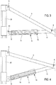
figure 1 représente schématiquement une vue en perspective d'un mode préférentiel, non limitatif, de réalisation d'un dispositif de structure selon l'invention, montrant une surélévation des montants avant, situés à gauche, conférant une pente décroissante depuis la gauche vers la droite de la figure ; - la
figure 2 représente schématiquement une vue de côté montrant un longeron du squelette de la structure, avec les bras ajustable dans une longueur intermédiaire en vue du repliement de ladite structure; - la
figure 3 représente schématiquement, partiellement et en transparence un détail d'un des bras ajustables de lafigure 2 , en position raccourcie ; - la
figure 4 représente schématiquement un détail similaire à lafigure 3 , montrant en transparence une position allongée intermédiaire d'un bras ajustable ; - les
figures 5, 6, 7 et 8 représentent schématiquement des vue de côté d'un dispositif de structure selon l'invention au cours de quatre étapes successives, réciproquement en position repliée de ladite structure pour son stockage et son transport, en position déployée dans laquelle le toit est droit, dans une première position d'allongement des bras ajustables provoquant l'inclinaison des montants et enfin dans une position redressée par ajustement de la longueur desdits montants pour conférer la pente à ladite toiture ; - la
figure 9 représente schématiquement une vue en perspective et en transparence d'un mode particulier de réalisation des moyens d'allongement et de raccourcissement d'un bras ajustable ; et - la
figure 10 représente schématiquement une vue en coupe transversale des moyens d'indexation de lafigure 9 . - La présente invention concerne un dispositif de structure 1 destinée à servir d'abri ou tente.
- Ladite structure 1 comprend des montants 2 supportant en partie supérieure un squelette 3. La structure 1 est destinée à recevoir en recouvrement un élément de couverture 4, formant alors la toiture. Dès lors, l'abri ainsi recouvert présente une forme globalement polyédrique.
- Selon le mode préférentiel de réalisation représenté sur la
figure 1 , l'abri est de forme rectangulaire et possède quatre montants 2. - Selon d'autres modes de réalisations, non représentés, l'abri peut avoir une autre forme, notamment à base hexagonale ou octogonale, comportant alors un plus grand nombre de montants 2.
- Ledit dispositif 1 est prévu déployable, susceptible de passer d'une position repliée vers une position déployée, et inversement. A cet effet, le squelette 3 est prévu déformable. En particulier, il est constitué d'éléments articulés entre eux, autorisant une déformation de la géométrie de l'ensemble de la structure 1, en vue de passer d'une position repliée vers la position déployée, au travers de positions intermédiaires, et inversement.
- Pour ce faire, longitudinalement, ledit squelette 3 comprend des longerons 5 mobiles. En outre, transversalement, le squelette 3 peut comprendre des traverses 50 prévues elles aussi mobiles, articulée de façon similaire aux longerons 5, pour former une armature transversale en croisillons.
- Plus particulièrement, un longeron 5 est constitué d'au moins une paire de bras 5a, 5b, articulés en ciseaux. Ainsi, ces bras 5a, 5b sont reliés, sensiblement en leur milieu au travers d'une articulation 6 à axe de rotation horizontal ou sensiblement horizontal.
- A ce titre, d'une part, la mobilité des longerons 5 est obtenue au travers d'articulations en ciseaux 6 de sa ou ses paires de bras.
- Comme illustré dans les figures, un longeron 5 peut être constitué d'une succession de telles paires de bras 5a, 5b articulés en ciseau. Au moins une extrémité de chaque bras 5a ; 5b d'une première paire est reliée à l'extrémité concordante d'un bras 5b ; 5a de la paire suivante, ceci par l'intermédiaire d'articulations en pivotement 7, notamment sous forme d'une biellette 70.
- D'autre part, la mobilité des longerons 5 est obtenue au moins avec les montants 2 au travers de points de pivotement 8 ; 80 avec les bras 5a, 5b. Cette jonction s'effectue au niveau des extrémités opposées des longerons 5. Selon l'invention, le point de pivotement 8, se situant à l'extrémité supérieure du montant 2 et reliant à cette dernière l'extrémité du bras, selon le cas, 5b ou 5a, est fixe. Tandis qu'un autre point inférieur de pivotement 80 est situé plus bas et est monté coulissant le long dudit montant 2. Ce point inférieur de pivotement 80 relie par conséquent de manière coulissante à ce montant 2 l'extrémité du bras, selon le cas, 5a ou 5b.
- Ainsi, lors des phases de repliement et déploiement, aux extrémités 60, 61 des longerons 5, les bras 5a, selon le cas 5b, sont reliés au travers des points inférieurs de pivotement 80 sur ces montants 2 et coulissent verticalement, assurant la déformation du squelette 3 pour un bon repliement de l'ensemble.
- On notera que la translation en coulissement peut s'opérer notamment par l'intermédiaire d'un chariot sur lequel est monté le point inférieur de pivotement 80, ledit chariot glissant au sein d'un rail, notamment constitué par une glissière ménagée au sein dudit montant 2. Ce chariot peut être verrouillé par rapport au montant 2 en plusieurs positions, en particulier en position haute lorsque la structure est déployée.
- Les articulations 6 et 7, ainsi que les points 8 et 80 sont particulièrement visibles sur la
figure 2 . - En outre, transversalement et comme indiqué plus haut, le squelette 3 peut comprendre des traverses 50 prévues elles aussi mobiles et formées d'une ou plusieurs paires de bras 5c, 5d articulés en ciseau de façon similaire à ceux des longerons 5.
- La mobilité des longerons 5 peut aussi être obtenue avec ces traverses 50 aux niveaux de points d'articulation 800. Plus particulièrement au niveau d'un tel point d'articulation 800, une extrémité d'un des bras 5c, 5d d'une paire correspondant à une traverse 50, vient coopérer, de manière articulée, dans une direction sensiblement perpendiculaire et au travers d'une pièce de jonction adaptée, notamment sous forme d'un croisillon, avec une extrémité d'un des bras, selon le cas 5a, 5b, d'une paire de bras d'un longeron 5, en formant un maillage croisé. Cette configuration est visible sur la
figure 1 . - Selon une caractéristique essentielle de la présente invention, la structure 1 permet d'obtenir une inclinaison de l'élément de couverture 4. De plus, le degré de la pente obtenu peut être réglé, notamment selon des angles prédéfinis.
- Pour ce faire, au moins un des bras 5a, 5b d'une paire de bras d'un longeron 5 est prévu ajustable longitudinalement au travers de moyens 9 d'allongement et de raccourcissement de sa longueur. En d'autres termes, un bras d'un longeron 5 peut être allongé ou raccourci, induisant un changement de la forme de la structure 1, conférant une asymétrie par rapport à un plan médian verticale transversal.
- De préférence, selon le mode préférentiel de réalisation, comme visible sur la
figure 2 , au moins un bras 5a est ajustable longitudinalement à une première extrémité 60 d'un longeron 5 et au moins un bras 5b, selon le cas d'une même paire ou non, à l'extrémité opposée 61 de ce longeron 5 est également ajustable longitudinalement. Cet ajustement en longueur des bras ajustable 5a, 5b est susceptible d'être obtenu au travers de moyens 9 d'allongement et de raccourcissement adaptés. - Dans un mode bien particulier de réalisation, au moins chaque longeron 5 situés aux extrémités latérales de la structure 1 comprennent des bras 5a, 5b pourvus de moyens 9 d'allongement et de raccourcissement.
- Dès lors, comme visible sur l'exemple de la
figure 7 , l'allongement des bras 5b à l'extrémité 61 des longerons 5 induit une inclinaison des montants 2b du côté de cette même extrémité 61. Tandis qu'un raccourcissement des bras 5a du côté de la première extrémité 60 de ces longerons 5 induit une inclinaison des montant 2a dans la même direction. Afin de redresser les montant 2a et 2b, il est nécessaire, essentiellement, d'allonger les montants 2a situés à gauche la structure 1. Il en découle la pente de l'élément de couverture 4. - On peut également souhaiter, une fois les montants 2a, 2b repositionnés verticalement, de rehausser la structure 1. Ceci peut être obtenu en augmentant la hauteur de tous les montants 2a, 2b, comme visible sur la
figure 8 . - Dans ce but, chaque montant 2 peut être avantageusement prévu déployable. Selon ce mode préférentiel, chaque montant 2 peut être prévu télescopique. En particulier, un montant 2 comprend au moins deux tronçons 20, intérieur et extérieur, coulissant l'un par rapport à l'autre pour passer d'une position escamotée lors du repliement de la structure 1, vers une position déployée lors du déploiement de ladite structure 1 et inversement.
- Par ailleurs, chaque bras 5a, 5b d'un longeron 5 équipé des moyens 9 est préférentiellement situé de part et d'autre, aux extrémités du squelette 3, le long des bords longitudinaux de la structure 1. Dès lors, les moyens 9 relient les bras, selon le cas 5a ou 5b, aux montants 2 aux niveaux des points inférieurs de pivotement 80, ainsi qu'au niveau des points d'articulation 800 des bras 5c, 5d des traverses 50 de l'ossature en croisillons.
- Comme visible sur les
figures 3 et 4 , les moyens 9 permettent d'augmenter ou de diminuer la longueur au niveau de l'extrémité équipée des bras ajustable 5a, 5b. - Plus particulièrement, selon le mode préférentiel de réalisation, lesdits moyens d'allongement et de raccourcissement 9 sont télescopiques, au travers de segments coulissants constituant chaque bras ajustable 5a, 5b.
- Plus avant, de façon non limitative, les moyens d'allongement et de raccourcissement 9 de chaque bras ajustable 5a, 5b comprennent à une extrémité distale 12 un fourreau 10, d'une part, monté coulissant extérieurement par rapport à un segment principal 11 dudit bras ajustable 5a, 5b et, d'autre part, rendu solidaire d'un point de pivotement 80 ou d'un point d'articulation 800.
- Plus précisément, ce fourreau 10 est rendu solidaire à l'une de ses extrémités du point de pivotement 80 (ou d'un point d'articulation 800).
- Ainsi, comme visible sur la
figure 4 , il est possible de coulisser en translation le segment principal 11 pour l'écarter ou selon le cas le rapprocher l'extrémité distal 12, créant un espace d'une longueur donnée correspondant à l'allongement ou au raccourcissement souhaité du bras ajustable 5a, 5b. - Selon un mode de réalisation préférentiel, lesdits moyens d'allongement et de raccourcissement 9 comprennent des moyens 13 d'indexage de la longueur de chaque bras ajustable 5a, 5b au niveau de positions, préférentiellement mais non exclusivement, extrêmes allongée et raccourcie, voire avantageusement aussi dans des positions intermédiaires. Ainsi, il est possible de régler et de bloquer la longueur de chaque bras 5a, 5b, donc d'un longeron 5.
- Toutefois, tous les moyens 9 peuvent ne pas être équipés d'indexation. En particulier, seuls les moyens 9 solidarisés aux montants 2 possèdent des moyens d'indexage 13, tandis que les autres, reliés à l'ossature transversale munie des traverses 50 en croisillons, n'en possèdent pas nécessairement, pouvant éventuellement coulisser librement. Dès lors, seuls les moyens 9 reliés aux montants 2 servent à l'indexage et au verrouillage.
- Selon encore un mode préférentiel de réalisation, comme visible sur les
figures 9 et 10 , lesdits moyens d'indexage 13 sont montés fixes à l'extrémité opposée dudit fourreau 10, notamment par l'intermédiaire d'une pièce solidarisée autour du fourreau 10. Ils comprennent un ergot 14 coopérant par insertion au travers d'orifices 15 ménagés en vis-à-vis et le long dudit segment principal 11. Cet ergot 14 est monté en translation au sein d'un logement conformé complémentairement. - L'ergot 14 peut aussi être équipé de moyens de rappel élastique, le repoussant dans un mouvement de translation vers une position d'insertion et de verrouillage. Ainsi, il suffit de tirer l'ergot 14, par l'intermédiaire de moyens de préhension 16 adaptés, puis de coulisser le segment principal du bras ajustable 5a, 5b par rapport au fourreau 10 jusqu'à ce qu'un orifice 15 se retrouve en face dudit ergot 14 et que ce dernier vienne être repoussé automatiquement pour s'y enclencher. Chaque orifice 15 permet alors de régler une position et une inclinaison particulière de la pente du dispositif 1.
- Les orifices 15 peuvent être espacés à intervalles réguliers ou non.
- On comprendra que ces moyens d'indexage 13 peuvent prendre diverses formes de réalisation ayant pour but d'immobiliser dans un positon donnée la longueur d'un bras ajustable 5a, 5b, telles que goupille, lame ressort avec bille, système vis écrou, etc...
- En outre, le déplacement des tronçons 20 de chaque montant 2 peut être lui aussi indexé permettant de les bloquer verticalement selon plusieurs positions, de préférence une position basse où les tronçons 20 sont entièrement escamotés, une position extrême de déploiement maximal dans laquelle l'ossature est surélevée, mais aussi au moins une position intermédiaire dans laquelle l'ossature est horizontale. L'indexage des positions le long des montants 2 peut avantageusement correspondre à l'indexage des moyens 9 au niveau des orifices 15.
- Préférentiellement, l'angle de la pente peut être indexée selon des valeurs angulaires déterminée, allant de 1 à 45 degrés, préférentiellement au moins 5 degrés, par intervalle de 1 à 5 degrés.
- Ainsi, le dispositif de structure 1 selon l'invention permet de rapidement et simplement conférer une pente à un abri, à partir d'un squelette 3 conformé en pantographes, ainsi que des croisillons, au moyen de l'allongement et du raccourcissement de certains des bras ajustables 5a, 5b de ses longerons 5, tout en conservant la géométrie nécessaire au repliement optimal d'une telle structure 1.
- En d'autres termes, la longueur variable d'au moins un longeron 5, de préférence plusieurs, permet la déformation des parallélogrammes du squelette 3, conférant à ce dernier, selon le cas, une régularité nécessaire au repliement de ladite structure 1 ou, contrairement, après déploiement, une irrégularité permettant d'imprimer à la toiture l'inclinaison souhaitée. De cette inclinaison et du caractère télescopique du ou des montants 2, en découle l'inclinaison, par rapport à l'horizontal, de la toiture, selon un sens de ladite structure 1, de préférence le sens longitudinal.
- De la même façon, l'invention peut être adaptée aux niveaux des traverses et du maillage transversal en croisillons, afin de conférer une inclinaison dans le sens transversal de la structure 1.
Claims (10)
- Dispositif de structure (1) déployable d'abri, comprenant des montants (2) supportant en partie supérieure un squelette (3) déformable comprenant des longerons (5) mobiles constitués d'au moins une paire de bras (5a, 5b) articulés en ciseaux et reliés au travers de points de pivotement (8 ; 80) à des montants (2), dont le point de pivotement (8), reliant à l'extrémité supérieure du montant (2) l'extrémité du bras, selon le cas, (5b ou 5a), étant fixe, tandis que l'un autre point inférieur de pivotement (80) étant situé plus bas et monté coulissant le long dudit montant (2) en reliant de manière coulissante à ce montant (2) l'extrémité du bras, selon le cas, (5a ou 5b) ; caractérisé par le fait qu'au moins un bras (5a, 5b) d'une paire de bras d'un longeron (5) est prévu ajustable longitudinalement au travers de moyens (9) d'allongement et de raccourcissement de sa longueur.
- Dispositif de structure (1) selon la revendication 1, caractérisé par le fait qu'au moins un bras (5a) est ajustable longitudinalement à une première extrémité (60) d'un longeron (5) et au moins un bras (5b), selon le cas d'une même paire ou non, à l'extrémité opposée (61) de ce longeron (5) est également ajustable longitudinalement, au travers de moyens (9) d'allongement et de raccourcissement.
- Dispositif de structure (1) selon l'une quelconque des revendications précédentes, caractérisé par le fait que lesdits moyens (9) d'allongement et de raccourcissement sont télescopiques, au travers de segments coulissants (10, 11) constituant chaque bras ajustable (5a, 5b).
- Dispositif de structure (1) selon la revendication 2 ou 3, caractérisé par le fait que lesdits moyens (9) d'allongement et de raccourcissement comprennent des moyens d'indexage (13) de la longueur de chaque bras ajustable (5a, 5b), notamment aux niveaux de positions extrêmes allongée et raccourcie.
- Dispositif de structure selon la revendication 3, caractérisé par le fait que les moyens (9) d'allongement et de raccourcissement de chaque bras ajustable (5a, 5b) comprennent un fourreau (10), d'une part, monté coulissant extérieurement par rapport à un segment principal (11) dudit bras ajustable (5a, 5b) et, d'autre part, rendu solidaire d'un point de pivotement (80) au niveau d'au moins un montant (2) .
- Dispositif de structure (1) selon la revendication 5, caractérisé par le fait que ledit fourreau (10) est rendu solidaire du point de pivotement (80).
- Dispositif de structure (1) selon la revendication 6, caractérisé par le fait que lesdits moyens d'indexage (13) sont montés fixes sur ledit fourreau (10) et comprennent un ergot (14) coopérant par insertion au travers d'orifices (15) ménagés en vis-à-vis et le long dudit segment principal (11).
- Dispositif de structure (1) selon l'une quelconque des revendications précédentes, caractérisé par le fait qu'au moins deux montants (2) disposés d'un même côté de la structure (1) et auxquels sont fixé par les points de pivotement (8 ; 80) de l'extrémité (60) d'un longeron (5) sont prévus télescopique.
- Dispositif de structure (1) selon l'une quelconque des revendications précédentes, caractérisé par le fait que tous les montants (2) sont prévus télescopique.
- Dispositif de structure (1) selon l'une quelconque des revendications précédentes, caractérisé par le fait que le squelette (3) comprend des traverses (50) prévues mobiles et formées d'une ou plusieurs paires de bras (5c, 5d) articulés en ciseau de façon similaire à ceux des longerons (5) coopérant avec les traverses (50) aux niveaux de points d'articulation (800).
Applications Claiming Priority (3)
| Application Number | Priority Date | Filing Date | Title |
|---|---|---|---|
| FR1561007A FR3043710A1 (fr) | 2015-11-16 | 2015-11-16 | Structure deployable a toit a une pente |
| FR1654227A FR3043709B1 (fr) | 2015-11-16 | 2016-05-12 | Structure deployable a toit a une pente |
| PCT/FR2016/052965 WO2017085398A1 (fr) | 2015-11-16 | 2016-11-16 | Dispositif de structure deployable d'abri |
Publications (2)
| Publication Number | Publication Date |
|---|---|
| EP3377716A1 EP3377716A1 (fr) | 2018-09-26 |
| EP3377716B1 true EP3377716B1 (fr) | 2019-08-07 |
Family
ID=70738241
Family Applications (1)
| Application Number | Title | Priority Date | Filing Date |
|---|---|---|---|
| EP16812985.6A Active EP3377716B1 (fr) | 2015-11-16 | 2016-11-16 | Dispositif de structure déployable d'abri |
Country Status (5)
| Country | Link |
|---|---|
| US (1) | US10662667B2 (fr) |
| EP (1) | EP3377716B1 (fr) |
| JP (1) | JP6949303B2 (fr) |
| FR (1) | FR3043709B1 (fr) |
| WO (1) | WO2017085398A1 (fr) |
Families Citing this family (4)
| Publication number | Priority date | Publication date | Assignee | Title |
|---|---|---|---|---|
| US11220835B2 (en) | 2019-10-08 | 2022-01-11 | Shelterlogic Corp. | Pop-up canopy |
| US11889828B2 (en) * | 2020-04-06 | 2024-02-06 | Jeremiah Banfield | Hunting blind |
| CN111762331B (zh) * | 2020-06-09 | 2021-10-15 | 福建通图信息技术有限公司 | 一种无人机防护用对拉型遮护装置 |
| CN114876276B (zh) * | 2022-03-29 | 2023-11-14 | 中国铁建重工集团股份有限公司 | 一种天幕工作装置 |
Family Cites Families (15)
| Publication number | Priority date | Publication date | Assignee | Title |
|---|---|---|---|---|
| JPS53133409U (fr) * | 1977-03-29 | 1978-10-23 | ||
| US4607656A (en) * | 1983-09-26 | 1986-08-26 | Carter Mark C | Quick erection collapsible shelter |
| US5085398A (en) * | 1988-10-19 | 1992-02-04 | Holcomb Grove R | Adjustable form brace |
| FI86796C (fi) * | 1990-02-13 | 1992-10-26 | Ahlstroem Oy | Anordning foer lutning av liggunderlag i sjukhussaeng |
| US6206020B1 (en) * | 1998-08-14 | 2001-03-27 | James P. Lynch | Collapsible canopy framework and structure with articulating scissor assemblies |
| US6141934A (en) * | 1998-12-07 | 2000-11-07 | World Shelters, Inc. | Folding frame system with foldable leg assembly and method of erecting a folding frame system |
| AT6563U1 (de) * | 2002-12-23 | 2003-12-29 | Expotrade Group Handelsges M B | Zelt |
| US7533498B2 (en) * | 2004-02-18 | 2009-05-19 | World Shelters, Inc. | Mechanically deployable expandable and collapsible structure and method for deploying a structure |
| DE102004053669A1 (de) * | 2004-11-03 | 2006-05-04 | Röder Zelt- und Veranstaltungsservice GmbH | Zelt mit variabler Form |
| FR2893653B1 (fr) * | 2005-11-18 | 2008-01-11 | Vitabri Sa | Montant telescopique pour structure pliable et telle structure |
| US8662096B2 (en) * | 2007-02-27 | 2014-03-04 | Vitabri, Societe Anonyme | Folding structure that can be unfolded and refolded quickly |
| FR2913043B1 (fr) * | 2007-02-27 | 2010-11-12 | Vitabri | Structure pliable a developpement et repliement rapide. |
| WO2010006344A1 (fr) * | 2008-06-11 | 2010-01-14 | Sunsmart Products (Pty) Ltd | Abri en tissu auto-portant pliable |
| US7703469B2 (en) * | 2008-06-13 | 2010-04-27 | Paxdanz, Llc | Portable adjustable shade structure |
| KR20130096950A (ko) * | 2012-02-23 | 2013-09-02 | 신재기 | 접철식 캐노피 프레임 및 이를 이용한 캐노피 |
-
2016
- 2016-05-12 FR FR1654227A patent/FR3043709B1/fr not_active Expired - Fee Related
- 2016-11-16 US US15/776,665 patent/US10662667B2/en active Active
- 2016-11-16 JP JP2018525381A patent/JP6949303B2/ja active Active
- 2016-11-16 WO PCT/FR2016/052965 patent/WO2017085398A1/fr active Application Filing
- 2016-11-16 EP EP16812985.6A patent/EP3377716B1/fr active Active
Non-Patent Citations (1)
| Title |
|---|
| None * |
Also Published As
| Publication number | Publication date |
|---|---|
| JP6949303B2 (ja) | 2021-10-13 |
| EP3377716A1 (fr) | 2018-09-26 |
| WO2017085398A1 (fr) | 2017-05-26 |
| JP2019500519A (ja) | 2019-01-10 |
| FR3043709A1 (fr) | 2017-05-19 |
| FR3043709B1 (fr) | 2019-11-08 |
| US20180328073A1 (en) | 2018-11-15 |
| US10662667B2 (en) | 2020-05-26 |
Similar Documents
| Publication | Publication Date | Title |
|---|---|---|
| EP3377716B1 (fr) | Dispositif de structure déployable d'abri | |
| EP1948889B1 (fr) | Montant telescopique pour structure pliable et telle structure | |
| AT5165U1 (de) | Freiarmschirm | |
| WO1991008806A1 (fr) | Mur d'escalade artificiel transportable | |
| EP2118408A1 (fr) | Structure pliable a deploiement et repliement rapides | |
| US20100230208A1 (en) | Convertible multipurpose ladder stabilizers | |
| FR2557909A1 (fr) | Abri leger en forme de tente. | |
| CA2414173A1 (fr) | Grue avec fleche articulee | |
| EP2806097B1 (fr) | Marchepied muni de roues escamotables, dont une roue avant montée basculante avec commande manuelle | |
| EP3011119B1 (fr) | Dispositif d'aménagement d'abri démontable et/ou pliable | |
| FR2987354A1 (fr) | Dispositif de structure depliable et repliable de type mat telescopique | |
| FR3043710A1 (fr) | Structure deployable a toit a une pente | |
| EP3030731B1 (fr) | Dispositif de structure de couverture exterieure d'un abri | |
| EP0300939A2 (fr) | Dispositif de déploiement et escamotage en faux-plafond d'une literie ou similaire | |
| CA2720809A1 (fr) | Dispositif permettant de reduire la prise au vent de la toile de protection d'un parasol ou autre abri | |
| WO1998004796A1 (fr) | Abri pliable equipe de poutres articulees a parallelogrammes deformables | |
| WO2013076123A1 (fr) | Tribune télescopique, motorisée, déplaçable | |
| FR3035570A3 (fr) | Modele de pare-soleil | |
| FR2634701A1 (fr) | Plate-forme roulante de transport, de montage et de demontage d'une structure de couverture deployable | |
| FR2672925A1 (fr) | Abri leger repliable. | |
| DE202023105525U1 (de) | Freiarm-Standschirm, insbesondere für Sonnen- und Regenschutz | |
| BE897210A (fr) | Fauteuil roulant repliable pour invalides | |
| FR3101088A1 (fr) | Echafaudage | |
| WO2019145630A1 (fr) | Structure de cadres articules déployables sur des rails | |
| DE202017002869U1 (de) | Sitzmöbel mit einem in Bezug auf ein Lehnenteil klappbaren Sitzteil |
Legal Events
| Date | Code | Title | Description |
|---|---|---|---|
| STAA | Information on the status of an ep patent application or granted ep patent |
Free format text: STATUS: UNKNOWN |
|
| STAA | Information on the status of an ep patent application or granted ep patent |
Free format text: STATUS: THE INTERNATIONAL PUBLICATION HAS BEEN MADE |
|
| PUAI | Public reference made under article 153(3) epc to a published international application that has entered the european phase |
Free format text: ORIGINAL CODE: 0009012 |
|
| STAA | Information on the status of an ep patent application or granted ep patent |
Free format text: STATUS: REQUEST FOR EXAMINATION WAS MADE |
|
| 17P | Request for examination filed |
Effective date: 20180419 |
|
| AK | Designated contracting states |
Kind code of ref document: A1 Designated state(s): AL AT BE BG CH CY CZ DE DK EE ES FI FR GB GR HR HU IE IS IT LI LT LU LV MC MK MT NL NO PL PT RO RS SE SI SK SM TR |
|
| AX | Request for extension of the european patent |
Extension state: BA ME |
|
| DAV | Request for validation of the european patent (deleted) | ||
| DAX | Request for extension of the european patent (deleted) | ||
| GRAP | Despatch of communication of intention to grant a patent |
Free format text: ORIGINAL CODE: EPIDOSNIGR1 |
|
| STAA | Information on the status of an ep patent application or granted ep patent |
Free format text: STATUS: GRANT OF PATENT IS INTENDED |
|
| INTG | Intention to grant announced |
Effective date: 20190416 |
|
| GRAS | Grant fee paid |
Free format text: ORIGINAL CODE: EPIDOSNIGR3 |
|
| GRAA | (expected) grant |
Free format text: ORIGINAL CODE: 0009210 |
|
| STAA | Information on the status of an ep patent application or granted ep patent |
Free format text: STATUS: THE PATENT HAS BEEN GRANTED |
|
| AK | Designated contracting states |
Kind code of ref document: B1 Designated state(s): AL AT BE BG CH CY CZ DE DK EE ES FI FR GB GR HR HU IE IS IT LI LT LU LV MC MK MT NL NO PL PT RO RS SE SI SK SM TR |
|
| REG | Reference to a national code |
Ref country code: GB Ref legal event code: FG4D Free format text: NOT ENGLISH |
|
| REG | Reference to a national code |
Ref country code: CH Ref legal event code: EP Ref country code: AT Ref legal event code: REF Ref document number: 1164121 Country of ref document: AT Kind code of ref document: T Effective date: 20190815 |
|
| REG | Reference to a national code |
Ref country code: DE Ref legal event code: R096 Ref document number: 602016018367 Country of ref document: DE |
|
| REG | Reference to a national code |
Ref country code: IE Ref legal event code: FG4D Free format text: LANGUAGE OF EP DOCUMENT: FRENCH |
|
| REG | Reference to a national code |
Ref country code: NL Ref legal event code: MP Effective date: 20190807 |
|
| REG | Reference to a national code |
Ref country code: LT Ref legal event code: MG4D |
|
| PG25 | Lapsed in a contracting state [announced via postgrant information from national office to epo] |
Ref country code: FI Free format text: LAPSE BECAUSE OF FAILURE TO SUBMIT A TRANSLATION OF THE DESCRIPTION OR TO PAY THE FEE WITHIN THE PRESCRIBED TIME-LIMIT Effective date: 20190807 Ref country code: LT Free format text: LAPSE BECAUSE OF FAILURE TO SUBMIT A TRANSLATION OF THE DESCRIPTION OR TO PAY THE FEE WITHIN THE PRESCRIBED TIME-LIMIT Effective date: 20190807 Ref country code: HR Free format text: LAPSE BECAUSE OF FAILURE TO SUBMIT A TRANSLATION OF THE DESCRIPTION OR TO PAY THE FEE WITHIN THE PRESCRIBED TIME-LIMIT Effective date: 20190807 Ref country code: NL Free format text: LAPSE BECAUSE OF FAILURE TO SUBMIT A TRANSLATION OF THE DESCRIPTION OR TO PAY THE FEE WITHIN THE PRESCRIBED TIME-LIMIT Effective date: 20190807 Ref country code: NO Free format text: LAPSE BECAUSE OF FAILURE TO SUBMIT A TRANSLATION OF THE DESCRIPTION OR TO PAY THE FEE WITHIN THE PRESCRIBED TIME-LIMIT Effective date: 20191107 Ref country code: BG Free format text: LAPSE BECAUSE OF FAILURE TO SUBMIT A TRANSLATION OF THE DESCRIPTION OR TO PAY THE FEE WITHIN THE PRESCRIBED TIME-LIMIT Effective date: 20191107 Ref country code: PT Free format text: LAPSE BECAUSE OF FAILURE TO SUBMIT A TRANSLATION OF THE DESCRIPTION OR TO PAY THE FEE WITHIN THE PRESCRIBED TIME-LIMIT Effective date: 20191209 Ref country code: SE Free format text: LAPSE BECAUSE OF FAILURE TO SUBMIT A TRANSLATION OF THE DESCRIPTION OR TO PAY THE FEE WITHIN THE PRESCRIBED TIME-LIMIT Effective date: 20190807 |
|
| REG | Reference to a national code |
Ref country code: AT Ref legal event code: MK05 Ref document number: 1164121 Country of ref document: AT Kind code of ref document: T Effective date: 20190807 |
|
| PG25 | Lapsed in a contracting state [announced via postgrant information from national office to epo] |
Ref country code: IS Free format text: LAPSE BECAUSE OF FAILURE TO SUBMIT A TRANSLATION OF THE DESCRIPTION OR TO PAY THE FEE WITHIN THE PRESCRIBED TIME-LIMIT Effective date: 20191207 Ref country code: ES Free format text: LAPSE BECAUSE OF FAILURE TO SUBMIT A TRANSLATION OF THE DESCRIPTION OR TO PAY THE FEE WITHIN THE PRESCRIBED TIME-LIMIT Effective date: 20190807 Ref country code: GR Free format text: LAPSE BECAUSE OF FAILURE TO SUBMIT A TRANSLATION OF THE DESCRIPTION OR TO PAY THE FEE WITHIN THE PRESCRIBED TIME-LIMIT Effective date: 20191108 Ref country code: RS Free format text: LAPSE BECAUSE OF FAILURE TO SUBMIT A TRANSLATION OF THE DESCRIPTION OR TO PAY THE FEE WITHIN THE PRESCRIBED TIME-LIMIT Effective date: 20190807 Ref country code: LV Free format text: LAPSE BECAUSE OF FAILURE TO SUBMIT A TRANSLATION OF THE DESCRIPTION OR TO PAY THE FEE WITHIN THE PRESCRIBED TIME-LIMIT Effective date: 20190807 Ref country code: AL Free format text: LAPSE BECAUSE OF FAILURE TO SUBMIT A TRANSLATION OF THE DESCRIPTION OR TO PAY THE FEE WITHIN THE PRESCRIBED TIME-LIMIT Effective date: 20190807 |
|
| PG25 | Lapsed in a contracting state [announced via postgrant information from national office to epo] |
Ref country code: TR Free format text: LAPSE BECAUSE OF FAILURE TO SUBMIT A TRANSLATION OF THE DESCRIPTION OR TO PAY THE FEE WITHIN THE PRESCRIBED TIME-LIMIT Effective date: 20190807 |
|
| PG25 | Lapsed in a contracting state [announced via postgrant information from national office to epo] |
Ref country code: IT Free format text: LAPSE BECAUSE OF FAILURE TO SUBMIT A TRANSLATION OF THE DESCRIPTION OR TO PAY THE FEE WITHIN THE PRESCRIBED TIME-LIMIT Effective date: 20190807 Ref country code: RO Free format text: LAPSE BECAUSE OF FAILURE TO SUBMIT A TRANSLATION OF THE DESCRIPTION OR TO PAY THE FEE WITHIN THE PRESCRIBED TIME-LIMIT Effective date: 20190807 Ref country code: DK Free format text: LAPSE BECAUSE OF FAILURE TO SUBMIT A TRANSLATION OF THE DESCRIPTION OR TO PAY THE FEE WITHIN THE PRESCRIBED TIME-LIMIT Effective date: 20190807 Ref country code: EE Free format text: LAPSE BECAUSE OF FAILURE TO SUBMIT A TRANSLATION OF THE DESCRIPTION OR TO PAY THE FEE WITHIN THE PRESCRIBED TIME-LIMIT Effective date: 20190807 Ref country code: AT Free format text: LAPSE BECAUSE OF FAILURE TO SUBMIT A TRANSLATION OF THE DESCRIPTION OR TO PAY THE FEE WITHIN THE PRESCRIBED TIME-LIMIT Effective date: 20190807 Ref country code: PL Free format text: LAPSE BECAUSE OF FAILURE TO SUBMIT A TRANSLATION OF THE DESCRIPTION OR TO PAY THE FEE WITHIN THE PRESCRIBED TIME-LIMIT Effective date: 20190807 |
|
| PG25 | Lapsed in a contracting state [announced via postgrant information from national office to epo] |
Ref country code: SM Free format text: LAPSE BECAUSE OF FAILURE TO SUBMIT A TRANSLATION OF THE DESCRIPTION OR TO PAY THE FEE WITHIN THE PRESCRIBED TIME-LIMIT Effective date: 20190807 Ref country code: SK Free format text: LAPSE BECAUSE OF FAILURE TO SUBMIT A TRANSLATION OF THE DESCRIPTION OR TO PAY THE FEE WITHIN THE PRESCRIBED TIME-LIMIT Effective date: 20190807 Ref country code: IS Free format text: LAPSE BECAUSE OF FAILURE TO SUBMIT A TRANSLATION OF THE DESCRIPTION OR TO PAY THE FEE WITHIN THE PRESCRIBED TIME-LIMIT Effective date: 20200224 Ref country code: CZ Free format text: LAPSE BECAUSE OF FAILURE TO SUBMIT A TRANSLATION OF THE DESCRIPTION OR TO PAY THE FEE WITHIN THE PRESCRIBED TIME-LIMIT Effective date: 20190807 |
|
| REG | Reference to a national code |
Ref country code: DE Ref legal event code: R097 Ref document number: 602016018367 Country of ref document: DE |
|
| PLBE | No opposition filed within time limit |
Free format text: ORIGINAL CODE: 0009261 |
|
| STAA | Information on the status of an ep patent application or granted ep patent |
Free format text: STATUS: NO OPPOSITION FILED WITHIN TIME LIMIT |
|
| PG2D | Information on lapse in contracting state deleted |
Ref country code: IS |
|
| PG25 | Lapsed in a contracting state [announced via postgrant information from national office to epo] |
Ref country code: MC Free format text: LAPSE BECAUSE OF FAILURE TO SUBMIT A TRANSLATION OF THE DESCRIPTION OR TO PAY THE FEE WITHIN THE PRESCRIBED TIME-LIMIT Effective date: 20190807 Ref country code: LU Free format text: LAPSE BECAUSE OF NON-PAYMENT OF DUE FEES Effective date: 20191116 |
|
| 26N | No opposition filed |
Effective date: 20200603 |
|
| PG25 | Lapsed in a contracting state [announced via postgrant information from national office to epo] |
Ref country code: SI Free format text: LAPSE BECAUSE OF FAILURE TO SUBMIT A TRANSLATION OF THE DESCRIPTION OR TO PAY THE FEE WITHIN THE PRESCRIBED TIME-LIMIT Effective date: 20190807 |
|
| PG25 | Lapsed in a contracting state [announced via postgrant information from national office to epo] |
Ref country code: IE Free format text: LAPSE BECAUSE OF NON-PAYMENT OF DUE FEES Effective date: 20191116 |
|
| PG25 | Lapsed in a contracting state [announced via postgrant information from national office to epo] |
Ref country code: CY Free format text: LAPSE BECAUSE OF FAILURE TO SUBMIT A TRANSLATION OF THE DESCRIPTION OR TO PAY THE FEE WITHIN THE PRESCRIBED TIME-LIMIT Effective date: 20190807 |
|
| PG25 | Lapsed in a contracting state [announced via postgrant information from national office to epo] |
Ref country code: HU Free format text: LAPSE BECAUSE OF FAILURE TO SUBMIT A TRANSLATION OF THE DESCRIPTION OR TO PAY THE FEE WITHIN THE PRESCRIBED TIME-LIMIT; INVALID AB INITIO Effective date: 20161116 Ref country code: MT Free format text: LAPSE BECAUSE OF FAILURE TO SUBMIT A TRANSLATION OF THE DESCRIPTION OR TO PAY THE FEE WITHIN THE PRESCRIBED TIME-LIMIT Effective date: 20190807 |
|
| PG25 | Lapsed in a contracting state [announced via postgrant information from national office to epo] |
Ref country code: MK Free format text: LAPSE BECAUSE OF FAILURE TO SUBMIT A TRANSLATION OF THE DESCRIPTION OR TO PAY THE FEE WITHIN THE PRESCRIBED TIME-LIMIT Effective date: 20190807 |
|
| PGFP | Annual fee paid to national office [announced via postgrant information from national office to epo] |
Ref country code: GB Payment date: 20231129 Year of fee payment: 8 |
|
| PGFP | Annual fee paid to national office [announced via postgrant information from national office to epo] |
Ref country code: FR Payment date: 20231117 Year of fee payment: 8 Ref country code: DE Payment date: 20231130 Year of fee payment: 8 Ref country code: CH Payment date: 20231202 Year of fee payment: 8 |
|
| PGFP | Annual fee paid to national office [announced via postgrant information from national office to epo] |
Ref country code: BE Payment date: 20231129 Year of fee payment: 8 |