EP3376572A1 - Oxidfeststoffbatterie - Google Patents
Oxidfeststoffbatterie Download PDFInfo
- Publication number
- EP3376572A1 EP3376572A1 EP18157917.8A EP18157917A EP3376572A1 EP 3376572 A1 EP3376572 A1 EP 3376572A1 EP 18157917 A EP18157917 A EP 18157917A EP 3376572 A1 EP3376572 A1 EP 3376572A1
- Authority
- EP
- European Patent Office
- Prior art keywords
- solid electrolyte
- layer
- solid
- active material
- oxide
- Prior art date
- Legal status (The legal status is an assumption and is not a legal conclusion. Google has not performed a legal analysis and makes no representation as to the accuracy of the status listed.)
- Granted
Links
Images


Classifications
-
- H—ELECTRICITY
- H01—ELECTRIC ELEMENTS
- H01M—PROCESSES OR MEANS, e.g. BATTERIES, FOR THE DIRECT CONVERSION OF CHEMICAL ENERGY INTO ELECTRICAL ENERGY
- H01M6/00—Primary cells; Manufacture thereof
- H01M6/14—Cells with non-aqueous electrolyte
- H01M6/18—Cells with non-aqueous electrolyte with solid electrolyte
- H01M6/185—Cells with non-aqueous electrolyte with solid electrolyte with oxides, hydroxides or oxysalts as solid electrolytes
-
- H—ELECTRICITY
- H01—ELECTRIC ELEMENTS
- H01M—PROCESSES OR MEANS, e.g. BATTERIES, FOR THE DIRECT CONVERSION OF CHEMICAL ENERGY INTO ELECTRICAL ENERGY
- H01M10/00—Secondary cells; Manufacture thereof
- H01M10/05—Accumulators with non-aqueous electrolyte
- H01M10/052—Li-accumulators
-
- H—ELECTRICITY
- H01—ELECTRIC ELEMENTS
- H01M—PROCESSES OR MEANS, e.g. BATTERIES, FOR THE DIRECT CONVERSION OF CHEMICAL ENERGY INTO ELECTRICAL ENERGY
- H01M10/00—Secondary cells; Manufacture thereof
- H01M10/05—Accumulators with non-aqueous electrolyte
- H01M10/052—Li-accumulators
- H01M10/0525—Rocking-chair batteries, i.e. batteries with lithium insertion or intercalation in both electrodes; Lithium-ion batteries
-
- H—ELECTRICITY
- H01—ELECTRIC ELEMENTS
- H01M—PROCESSES OR MEANS, e.g. BATTERIES, FOR THE DIRECT CONVERSION OF CHEMICAL ENERGY INTO ELECTRICAL ENERGY
- H01M10/00—Secondary cells; Manufacture thereof
- H01M10/05—Accumulators with non-aqueous electrolyte
- H01M10/056—Accumulators with non-aqueous electrolyte characterised by the materials used as electrolytes, e.g. mixed inorganic/organic electrolytes
- H01M10/0561—Accumulators with non-aqueous electrolyte characterised by the materials used as electrolytes, e.g. mixed inorganic/organic electrolytes the electrolyte being constituted of inorganic materials only
- H01M10/0562—Solid materials
-
- H—ELECTRICITY
- H01—ELECTRIC ELEMENTS
- H01M—PROCESSES OR MEANS, e.g. BATTERIES, FOR THE DIRECT CONVERSION OF CHEMICAL ENERGY INTO ELECTRICAL ENERGY
- H01M10/00—Secondary cells; Manufacture thereof
- H01M10/05—Accumulators with non-aqueous electrolyte
- H01M10/058—Construction or manufacture
-
- H—ELECTRICITY
- H01—ELECTRIC ELEMENTS
- H01M—PROCESSES OR MEANS, e.g. BATTERIES, FOR THE DIRECT CONVERSION OF CHEMICAL ENERGY INTO ELECTRICAL ENERGY
- H01M10/00—Secondary cells; Manufacture thereof
- H01M10/05—Accumulators with non-aqueous electrolyte
- H01M10/058—Construction or manufacture
- H01M10/0585—Construction or manufacture of accumulators having only flat construction elements, i.e. flat positive electrodes, flat negative electrodes and flat separators
-
- H—ELECTRICITY
- H01—ELECTRIC ELEMENTS
- H01M—PROCESSES OR MEANS, e.g. BATTERIES, FOR THE DIRECT CONVERSION OF CHEMICAL ENERGY INTO ELECTRICAL ENERGY
- H01M4/00—Electrodes
- H01M4/02—Electrodes composed of, or comprising, active material
- H01M4/04—Processes of manufacture in general
- H01M4/0402—Methods of deposition of the material
- H01M4/0407—Methods of deposition of the material by coating on an electrolyte layer
-
- H—ELECTRICITY
- H01—ELECTRIC ELEMENTS
- H01M—PROCESSES OR MEANS, e.g. BATTERIES, FOR THE DIRECT CONVERSION OF CHEMICAL ENERGY INTO ELECTRICAL ENERGY
- H01M4/00—Electrodes
- H01M4/02—Electrodes composed of, or comprising, active material
- H01M4/04—Processes of manufacture in general
- H01M4/0471—Processes of manufacture in general involving thermal treatment, e.g. firing, sintering, backing particulate active material, thermal decomposition, pyrolysis
-
- H—ELECTRICITY
- H01—ELECTRIC ELEMENTS
- H01M—PROCESSES OR MEANS, e.g. BATTERIES, FOR THE DIRECT CONVERSION OF CHEMICAL ENERGY INTO ELECTRICAL ENERGY
- H01M4/00—Electrodes
- H01M4/02—Electrodes composed of, or comprising, active material
- H01M4/04—Processes of manufacture in general
- H01M4/049—Manufacturing of an active layer by chemical means
- H01M4/0497—Chemical precipitation
-
- H—ELECTRICITY
- H01—ELECTRIC ELEMENTS
- H01M—PROCESSES OR MEANS, e.g. BATTERIES, FOR THE DIRECT CONVERSION OF CHEMICAL ENERGY INTO ELECTRICAL ENERGY
- H01M4/00—Electrodes
- H01M4/02—Electrodes composed of, or comprising, active material
- H01M4/13—Electrodes for accumulators with non-aqueous electrolyte, e.g. for lithium-accumulators; Processes of manufacture thereof
- H01M4/134—Electrodes based on metals, Si or alloys
-
- H—ELECTRICITY
- H01—ELECTRIC ELEMENTS
- H01M—PROCESSES OR MEANS, e.g. BATTERIES, FOR THE DIRECT CONVERSION OF CHEMICAL ENERGY INTO ELECTRICAL ENERGY
- H01M4/00—Electrodes
- H01M4/02—Electrodes composed of, or comprising, active material
- H01M4/13—Electrodes for accumulators with non-aqueous electrolyte, e.g. for lithium-accumulators; Processes of manufacture thereof
- H01M4/139—Processes of manufacture
- H01M4/1395—Processes of manufacture of electrodes based on metals, Si or alloys
-
- H—ELECTRICITY
- H01—ELECTRIC ELEMENTS
- H01M—PROCESSES OR MEANS, e.g. BATTERIES, FOR THE DIRECT CONVERSION OF CHEMICAL ENERGY INTO ELECTRICAL ENERGY
- H01M4/00—Electrodes
- H01M4/02—Electrodes composed of, or comprising, active material
- H01M4/36—Selection of substances as active materials, active masses, active liquids
- H01M4/38—Selection of substances as active materials, active masses, active liquids of elements or alloys
- H01M4/386—Silicon or alloys based on silicon
-
- H—ELECTRICITY
- H01—ELECTRIC ELEMENTS
- H01M—PROCESSES OR MEANS, e.g. BATTERIES, FOR THE DIRECT CONVERSION OF CHEMICAL ENERGY INTO ELECTRICAL ENERGY
- H01M2300/00—Electrolytes
- H01M2300/0017—Non-aqueous electrolytes
- H01M2300/0065—Solid electrolytes
- H01M2300/0068—Solid electrolytes inorganic
- H01M2300/0071—Oxides
-
- H—ELECTRICITY
- H01—ELECTRIC ELEMENTS
- H01M—PROCESSES OR MEANS, e.g. BATTERIES, FOR THE DIRECT CONVERSION OF CHEMICAL ENERGY INTO ELECTRICAL ENERGY
- H01M2300/00—Electrolytes
- H01M2300/0088—Composites
- H01M2300/0094—Composites in the form of layered products, e.g. coatings
-
- H—ELECTRICITY
- H01—ELECTRIC ELEMENTS
- H01M—PROCESSES OR MEANS, e.g. BATTERIES, FOR THE DIRECT CONVERSION OF CHEMICAL ENERGY INTO ELECTRICAL ENERGY
- H01M4/00—Electrodes
- H01M4/02—Electrodes composed of, or comprising, active material
- H01M4/04—Processes of manufacture in general
- H01M4/0402—Methods of deposition of the material
- H01M4/0421—Methods of deposition of the material involving vapour deposition
- H01M4/0423—Physical vapour deposition
- H01M4/0426—Sputtering
-
- Y—GENERAL TAGGING OF NEW TECHNOLOGICAL DEVELOPMENTS; GENERAL TAGGING OF CROSS-SECTIONAL TECHNOLOGIES SPANNING OVER SEVERAL SECTIONS OF THE IPC; TECHNICAL SUBJECTS COVERED BY FORMER USPC CROSS-REFERENCE ART COLLECTIONS [XRACs] AND DIGESTS
- Y02—TECHNOLOGIES OR APPLICATIONS FOR MITIGATION OR ADAPTATION AGAINST CLIMATE CHANGE
- Y02E—REDUCTION OF GREENHOUSE GAS [GHG] EMISSIONS, RELATED TO ENERGY GENERATION, TRANSMISSION OR DISTRIBUTION
- Y02E60/00—Enabling technologies; Technologies with a potential or indirect contribution to GHG emissions mitigation
- Y02E60/10—Energy storage using batteries
-
- Y—GENERAL TAGGING OF NEW TECHNOLOGICAL DEVELOPMENTS; GENERAL TAGGING OF CROSS-SECTIONAL TECHNOLOGIES SPANNING OVER SEVERAL SECTIONS OF THE IPC; TECHNICAL SUBJECTS COVERED BY FORMER USPC CROSS-REFERENCE ART COLLECTIONS [XRACs] AND DIGESTS
- Y02—TECHNOLOGIES OR APPLICATIONS FOR MITIGATION OR ADAPTATION AGAINST CLIMATE CHANGE
- Y02P—CLIMATE CHANGE MITIGATION TECHNOLOGIES IN THE PRODUCTION OR PROCESSING OF GOODS
- Y02P70/00—Climate change mitigation technologies in the production process for final industrial or consumer products
- Y02P70/50—Manufacturing or production processes characterised by the final manufactured product
Definitions
- the disclosure relates to an oxide all-solid-state battery excellent in lithium ion conductivity and joint strength between an anode active material layer and solid electrolyte layer thereof.
- An all-solid-state battery is such a battery that the cathode, the anode and the electrolyte layer present between the electrodes are all solid.
- an oxide all-solid-state battery comprising an oxide solid electrolyte is advantageous in that it is easy to handle in the air compared to a sulfide all-solid-state battery that may produce hydrogen sulfide.
- Li-La-Zr-O-based solid electrolyte i.e., a garnet-type oxide solid electrolyte
- a carbon anode has been used as the anode of an all-solid-state battery.
- the theoretical capacity of the carbon anode is only 372 mAhg -1 . Therefore, to increase the anode capacity, various kinds of anode materials have been developed. Of them, a silicon anode has attracted attention since, when it is sufficiently lithiated (Li 22 Si 5 ), the theoretical capacity is as high as 4200 mAhg -1 .
- oxide solid electrolytes For example, a perovskite-type oxide solid electrolyte such as (Li, La)TiO 3 and a nasicon-type oxide solid electrolyte such as Li(Al, Ti)(PO 4 ) 3 are known as oxide solid electrolytes. They contain elements such as Ti and Ga. The reduction potentials of Ti and Ga are higher than the potential of the silicon anode. Therefore, in oxide all-solid-state batteries comprising such oxide solid electrolytes, the silicon anode cannot be used since the oxide solid electrolytes cause reductive decomposition.
- the garnet-type oxide solid electrolyte since the reduction potential of the garnet-type oxide solid electrolyte is lower than the potential of the silicon anode, the garnet-type oxide solid electrolyte can be used in an oxide all-solid-state battery in combination with the silicon anode.
- Patent Literature 1 discloses a lithium battery comprising a solid electrolyte layer which comprises Li, La, Zr, Al, Si and O, which has a garnet-type structure, and which is a sintered body. Also in Patent Literature 1, there is a description of the use of Si as an anode active material.
- Patent Literature 1 Japanese Patent Application Laid-Open No. 2012-018792
- Patent Literature 1 an experimental example of producing a battery by combining a garnet-type oxide solid electrolyte with an anode active material containing Si, is not disclosed. This is considered to be because the production or charge and discharge of the battery is difficult in the prior art due to the following reasons.
- silicon particles are a very hard substance. Therefore, it is difficult to dispose such silicon particles and a solid electrolyte with securing a sufficient contact area therebetween.
- the garnet-type oxide solid electrolyte generally has a high sintering temperature of 1,200°C. Meanwhile, silicon itself has an oxidation temperature of about 700°C. When silicon is oxidized, it is converted into silicon oxide (SiO 2 ). A battery containing such SiO 2 cannot be charged and discharged. Therefore, when the garnet-type oxide solid electrolyte and silicon are tried to be joined by sintering them, SiO 2 is produced before they are joined. Therefore, a joined body thus obtained cannot be used as a battery material.
- An object of the disclosed embodiments is to provide an oxide all-solid-state battery excellent in lithium ion conductivity and joint strength between the anode active material layer and solid electrolyte layer thereof.
- an oxide all-solid-state battery comprising a cathode active material layer, an anode active material layer mainly comprising silicon, and a solid electrolyte layer disposed between the cathode active material layer and the anode active material layer, wherein the solid electrolyte layer is a layer mainly comprising a garnet-type oxide solid electrolyte sintered body represented by the following formula (1): Formula (1): (Li x-3y-z , E y , H z )L ⁇ M ⁇ O ⁇ where E is at least one kind of element selected from the group consisting of Al and Ga; L is at least one kind of element selected from the group consisting of an alkaline-earth metal element and a lanthanoid element; M is at least one kind of element selected from a transition element that can be six-coordinated with oxygen and typical elements in the Groups 12 to 15; x, y and z are real numbers that satisfy 5 ⁇ x-3y-z ⁇ 7,
- the solid electrolyte interface layer may comprise a Si element, an O element and a Li element.
- An average thickness of the solid electrolyte interface layer may be 1 nm or more and 800 nm or less.
- the anode active material layer may be an amorphous layer mainly comprising silicon.
- a method for producing the above-described oxide all-solid-state battery comprising the steps of: attaching a liquid silicon material to at least a part of a surface of the garnet-type oxide solid electrolyte represented by the formula (1), and heating the garnet-type oxide solid electrolyte to which the liquid silicon material is attached, in an inert atmosphere and a temperature condition of 400°C or more and 500°C or less.
- the oxide all-solid-state battery according to the disclosed embodiments comprises the specific solid electrolyte interface layer between the anode active material layer mainly comprising silicon and the solid electrolyte layer mainly comprising the garnet-type oxide solid electrolyte sintered body. Therefore, excellent lithium ion conductivity and joint strength can be obtained between the anode active material layer and the solid electrolyte layer. According to the production method of the disclosed embodiments, joining of the anode active material layer and the solid electrolyte layer, which has been impossible until now, can be achieved by using the liquid silicon material.
- the oxide all-solid-state battery according to the disclosed embodiments is an oxide all-solid-state battery comprising a cathode active material layer, an anode active material layer mainly comprising silicon, and a solid electrolyte layer disposed between the cathode active material layer and the anode active material layer, wherein the solid electrolyte layer is a layer mainly comprising a garnet-type oxide solid electrolyte sintered body represented by the following formula (1): Formula (1): (Li x-3y-z , E y , H z )L ⁇ M ⁇ O ⁇ where E is at least one kind of element selected from the group consisting of Al and Ga; L is at least one kind of element selected from the group consisting of an alkaline-earth metal element and a lanthanoid element; M is at least one kind of element selected from a transition element that can be six-coordinated with oxygen and typical elements in the Groups 12 to 15; x, y and z are real numbers that satisfy 5 ⁇ x
- FIG. 1 is a view of an example of the layer structure of the oxide all-solid-state battery according to the disclosed embodiments, and it is also a schematic sectional view of the oxide all-solid-state battery cut in the laminating direction.
- the thicknesses of the layers of the disclosed embodiments are not limited to those shown in FIG. 1 .
- An oxide all-solid-state battery 100 comprises a cathode active material layer 1, an anode active material layer 2, and a solid electrolyte layer 3 disposed between the cathode active material layer 1 and the anode active material layer 2.
- the oxide all-solid-state battery comprises a solid electrolyte interface layer 4 between the anode active material layer 2 and the solid electrolyte layer 3.
- a cathode current collector may be provided on a side of the cathode active material layer 1, which is opposite to the side facing the solid electrolyte layer 3.
- An anode current collector may be provided on a side of the anode active material layer 2, which is opposite to the side facing the solid electrolyte layer 3.
- the anode active material layer is not particularly limited, as long as it is a layer mainly comprising silicon.
- mainly comprising silicon means that silicon represents the largest of all elements contained in the anode active material layer. More specifically, silicon atoms account for more than 50 atm% of all atoms contained in the anode active material layer.
- the anode active material layer, the solid electrolyte interface layer and the solid electrolyte layer are strongly joined; therefore, it is sometimes difficult to differentiate between the layers by a section thereof.
- the layers can be differentiated by checking the element distribution of each layer by line analysis, which is an elemental analysis method, using energy dispersive X-ray spectroscopy (EDX) with a scanning electron microscope (SEM) (hereinafter it may be referred to as SEM-EDX) (see (b) shown in FIG. 5 ). It can be said that, as a result of this elemental analysis, a part where the Si element is relatively heavily detected, is the anode active material layer.
- line analysis which is an elemental analysis method, using energy dispersive X-ray spectroscopy (EDX) with a scanning electron microscope (SEM) (hereinafter it may be referred to as SEM-EDX) (see (b) shown in FIG. 5 ).
- the whole of the part where the Si element is present is the anode active material layer.
- the boundary between the anode active material layer and the anode current collector can be determined as the part where the Si element is present and where the element derived from the anode current collector (such as gold) accounts for the largest proportion. More specifically, a region where it is difficult to differentiate between the anode active material layer and the anode current collector, is divided by the boundary.
- a region where the Si element is more than a certain level and accounts for a large proportion can be determined as the anode active material layer, and a region where the element derived from the anode current collector is more than a certain level and accounts for a large proportion, can be determined as the anode current collector.
- the boundary between the two layers can be determined as a part where the Si element is present and where the element derived from the solid electrolyte interface layer (such as oxygen) accounts for the largest proportion. More specifically, a region where it is difficult to differentiate between the anode active material layer and the solid electrolyte interface layer, is divided by the boundary. Then, a region where the Si element is more than a certain level and accounts for a large proportion, is determined as the anode active material layer, and a region where the element derived from the solid electrolyte interface layer is more than a certain level and accounts for a large proportion, can be determined as the solid electrolyte interface layer.
- the anode active material layer can be an amorphous layer mainly comprising silicon.
- the amorphous layer means a layer in which atoms do not form a crystal having a regular and periodical arrangement and are solid.
- the anode active material layer can be an amorphous silicon layer.
- the average thickness of the anode active material layer can be 0.1 ⁇ m or more and 100 ⁇ m or less. It is preferably 1 ⁇ m or more and 50 ⁇ m or less, and more preferably 2 ⁇ m or more and 10 ⁇ m or less.
- a sufficient discharge capacity may not be obtained.
- the capacity utilization rate of the anode may decrease.
- the thickness is a value obtained by measuring the thicknesses of 3 to 10 points of the layer by means of an electron microscope, etc., and averaging the results (measured thicknesses).
- the solid electrolyte layer is a layer mainly comprising the garnet-type oxide solid electrolyte sintered body (hereinafter, it may be simply referred to as "sintered body") represented by the following formula (1): Formula (1): (Li x-3y-z , E y , H z )L ⁇ M ⁇ O ⁇
- garnet-type oxide solid electrolyte sintered body mainly comprising the garnet-type oxide solid electrolyte sintered body
- the garnet-type oxide solid electrolyte sintered body represented by the formula (1) accounts for more than 50% by mass of the total mass of the solid electrolyte layer.
- the composition ratio (x-3y-z) of the lithium shown in the above formula (1) is a real number in a range of from 5 to 7. Since the composition ratio of the lithium is in this range, the lithium ion conductivity of the solid electrolyte layer can be kept high.
- the composition ratio of the lithium is more than 7, the crystal structure of the sintered body changes from a cubic structure to a tetragonal structure and impairs crystallite symmetry. As a result, the lithium ion conductivity of the solid electrolyte layer is considered to deteriorate.
- the composition ratio of the lithium is less than 5, the lithium is less likely to enter the crystal structure of the sintered body and results in a decrease in lithium occupancy. As a result, the lithium ion conductivity of the solid electrolyte layer is considered to decrease.
- the element L in the formula (1) is not particularly limited, as long as it is at least one kind of element selected from an alkaline-earth metal element and a lanthanoid element. Whichever element is selected, the difference in the crystal structure of the sintered body is small, and the resulting sintered body obtains excellent ion conductivity.
- the alkaline-earth metal element examples include, but are not limited to, Ca, Sr, Ba and Ra.
- the element L La is preferred since better ion conductivity is obtained.
- composition ratio of the element L (the real number ⁇ in the formula (1)) is a real number of 2.5 or more and 3.5 or less.
- the element M in the formula (1) is not particularly limited, as long as it is at least one kind of element selected from a transition element that can be six-coordinated with oxygen and typical elements in the Groups 12 to 15. Whichever element is selected, the difference in the crystal structure of the sintered body is small, and the resulting sintered body obtains excellent ion conductivity.
- the element M is preferably Sc, Y, Ti, Zr, Hf, V, Nb, Ta, Cr, Mo, W, Mn, Fe, Co, Ni, Cu, Zn, Cd, Al, Ga, Ge, Sn, Sb, Bi, etc.
- the element M is more preferably at least one kind of element selected from the group consisting of Zr, Nb and Ta. This is because, since these elements has a relatively large ionic radius, a contraction in crystal lattice can be suppressed and, as a result, a deterioration in lithium ion conductivity can be suppressed.
- the element M is still more preferably at least one element selected from Zr and Nb.
- composition ratio of the element M (the real number ⁇ in the formula (1)) is a real number of 1.5 or more and 2.5 or less.
- the sintered body can contain at least one element selected from Al and Ga as the element E.
- the composition ratio of the element E the real number y in the formula (1)
- the crystal structure of the sintered body can be stable.
- the sintered body can contain a proton.
- the composition ratio of the proton (the real number z in the formula (1)) is less than 2.0. As long as the proton is in the range of the composition ratio, the difference in the crystal structure of the sintered body is small, and the sintered body can be obtained by heating at lower heating temperature than ever before.
- composition ratio of oxygen atoms (the real number ⁇ in the formula (1)) is a real number of 11 or more and 13 or less.
- examples include, but are not limited to, Li 6.75 La 3 Zr 1.75 Nb 0.25 O 12 , Li 6.4 La 3 Zr 1.4 Nb 0.6 O 12 , Li 6.5 La 3 Zr 1.7 Nb 0.3 O 12 , (Li 6.2 Al 0.2 ) La 3 Zr 1.7 Nb 0.3 O 12 , (Li 6.2 Ga 0.2 )La 3 Zn 1.7 Nb 0.3 O 12 , and Li 5.4 H 1.4 La 3 Zn 1.7 Nb 0.3 O 12 .
- the crystallinity of the sintered body is not particularly limited and can be any one of monocrystalline, polycrystalline and amorphous.
- the average thickness of the solid electrolyte layer is not particularly limited, as long as it is a thickness in a range that is generally selected as the average thickness of the solid electrolyte layer of an all-solid-state battery.
- the average thickness of the solid electrolyte layer can be 0.1 ⁇ m or more and 100 ⁇ m or less. It is preferably 1 ⁇ m or more and 50 ⁇ m or less, and more preferably 2 ⁇ m or more and 30 ⁇ m or less.
- the solid electrolyte layer In the case of differentiating the solid electrolyte layer by, for example, line analysis (an elemental analysis method) using SEM-EDX, a part where O, the element L (such as La) and the element M (such as Zr) are heavily detected, can be said to be the solid electrolyte layer. However, it cannot be said that the whole of the part where these elements are heavily present is the solid electrolyte layer.
- the solid electrolyte layer and the solid electrolyte interface layer can be differentiated from each other by the presence and absence of the Si element.
- a part where the Si element is present can be determined as the solid electrolyte interface layer, and a part where the Si element is not present can be determined as the solid electrolyte layer.
- the solid electrolyte interface layer comprises at least a Si element and an O element. These two kinds of elements can be confirmed by, for example, elemental analysis using SEM-EDX.
- the solid electrolyte interface layer may be such a layer that oxygen is diffused in silicon.
- the solid electrolyte interface layer can further comprise a Li element.
- a Li element By containing the Li element, the lithium ion conductivity between the solid electrolyte layer and the anode active material layer is increased and enables excellent charge and discharge of a battery.
- the Li element in the solid electrolyte interface layer can be confirmed by, for example, a known measurement method such as micro X-ray or secondary ion mass spectrometry (SIMS).
- the solid electrolyte interface layer was confirmed to have a crystal structure that the anode active material layer and the solid electrolyte layer do not have.
- the crystal structure of the solid electrolyte interface layer can be confirmed by X-ray diffractometry (XRD). Since the solid electrolyte interface layer is a very thin layer, it is difficult to cut out only the solid electrolyte interface layer for use in XRD. Therefore, in general, the laminate comprising at least the anode active material layer, the solid electrolyte interface layer and the solid electrolyte layer is subjected to XRD measurement.
- XRD measurement conditions are as follows, for example:
- the position of each peak may have a slight margin.
- the allowable margin is a margin of ⁇ 0.5° of the value of 2 ⁇ .
- ⁇ 0.5° means the allowable range of the margin of the value of 2 ⁇ .
- the average thickness of the solid electrolyte interface layer can be 1 nm or more and 1,000 nm or less. It is preferably 10 nm or more and 900 nm or less, and more preferably 200 nm or more and 800 nm or less.
- the joint strength between the anode active material layer and the solid electrolyte layer may be weak.
- the solid electrolyte interface layer is too thick, the distance between the anode active material layer and the solid electrolyte layer is increased and may result in an increase in battery resistance.
- the solid electrolyte interface layer two materials that are absolutely different in properties, that is, metal (silicon) and ceramics (the garnet-type oxide solid electrolyte sintered body) are joined by the solid electrolyte interface layer.
- the joint strength is much higher than a joint strength in a laminate obtained by forming a silicon active material layer on the surface of a garnet-type oxide solid electrolyte by a gas phase method (the below-described Reference Example 1).
- the solid electrolyte interface layer has excellent ion conductivity and is effective in decreasing the electrical resistance of an interface between the anode active material layer and the solid electrolyte layer.
- the solid electrolyte interface layer In the case of differentiating the solid electrolyte interface layer by, for example, line analysis (an elemental analysis method) using SEM-EDX, a part where O and Si are relatively heavily detected and the element L (such as La) and the element M (such as Zr) are slightly detected, can be said to be the solid electrolyte interface layer.
- the whole of the part where these elements are present is the solid electrolyte interface layer.
- the boundary between the two layers can be determined as the part where the Si element is present and where the element derived from the solid electrolyte interface layer (such as oxygen) accounts for the largest proportion.
- the solid electrolyte layer and the solid electrolyte interface layer can be differentiated from each other by the presence and absence of the Si element.
- the cathode active material layer is not particularly limited, as long as it is a layer containing a cathode active material.
- the cathode active material is not particularly limited, as long as it releases lithium ions at the time of discharge, when it is used in combination with the anode active material layer.
- examples include, but are not limited to, a lithium metal, LiCoO 2 , LiMnO 2 , Li 2 NiMn 3 O 8 , LiVO 2 , LiCrO 2 , LiFePO 4 , LiCoPO 4 , LiNiO 2 , and LiNi 1/3 Co 1/3 Mn 1/3 O 2 .
- the cathode active material layer can contain an electroconductive material, a solid electrolyte material, a binder, etc.
- examples include, but are not limited to, SUS, aluminum, nickel, iron, titanium and carbon. Of them, SUS is preferred.
- examples include, but are not limited to, gold, SUS, copper, nickel and carbon. Of them, gold is preferred.
- the thickness, shape and so on of the cathode and anode current collectors can be appropriately selected, depending on the intended application, etc., of the oxide all-solid-state battery.
- the production method is a method for producing the above-described oxide all-solid-state battery, the method comprising the steps of: attaching a liquid silicon material to at least a part of a surface of the garnet-type oxide solid electrolyte represented by the formula (1), and heating the garnet-type oxide solid electrolyte to which the liquid silicon material is attached, in an inert atmosphere and a temperature condition of 400°C or more and 500°C or less.
- the production method according to the disclosed embodiments comprises (1) the step of attaching the liquid silicon material to the garnet-type oxide solid electrolyte and (2) the heating step.
- the production method according to the disclosed embodiments is not limited to these two steps.
- it can comprise a step of synthesizing the garnet-type oxide solid electrolyte before the step (1). It can further comprise other steps after the step (2), such as a step of forming the cathode active material layer on the sintered body and a step of providing current collectors.
- the garnet-type oxide solid electrolyte used as a raw material is not particularly limited, as long as it contains the composition represented by the above formula (1).
- the garnet-type oxide solid electrolyte can be synthesized in advance before the step (1) and then used in the step (1), or a commercially-available garnet-type oxide solid electrolyte can be used in the step (1).
- the garnet-type oxide solid electrolyte can be synthesized by a solid phase reaction method, for example.
- examples include, but are not limited to, Li 6.75 La 3 Zr 1.75 Nb 0.25 O 12 , Li 6.4 La 3 Zr 1.4 Nb 0.6 O 12 , Li 6.5 La 3 Zr 1.7 Nb 0.3 O 12 , (Li 6.2 Al 0.2 )La 3 Zn 1.7 Nb 0.3 O 12 , (Li 6.2 Ga 0.2 )La 3 Zr 1.7 Nb 0.3 O 12 , and Li 5.4 H 1.4 La 3 Zr 1.7 Nb 0.3 O 12 .
- the crystallinity of the garnet-type oxide solid electrolyte is not particularly limited and can be any one of monocrystalline, polycrystalline and amorphous.
- the "liquid silicon material” means a liquid containing at least one selected from the group consisting of a low-order silane compound, a low-order silane composition, a high-order silane compound and a high-order silane composition.
- the low-order silane compound means a silane or halogenated silane compound with a relatively small molecular weight.
- the low-order silane compound is preferably one that is in a gas or liquid state at normal temperature and under normal pressure.
- the low-order silane compound is preferably a silane or halogenated silane compound containing one or more cyclic structures per molecule.
- silane compound selected from the group consisting of a compound represented by the following formula (i) and a compound represented by the following formula (ii): Formula (i) : Si i X 2i Formula (ii) : Si j X 2j-2 where X is a hydrogen atom or a halogen atom; i is an integer of from 3 to 8; and j is an integer of from 4 to 14.
- the below-described high-order silane compound is obtained by polymerizing a low-order silane compound.
- the low-order silane compound examples include, but are not limited to, a low-order silane compound that can be polymerized into a high-order silane compound by light irradiation, electron beam irradiation, heating, etc.
- a low-order silane compound that can be changed into a high-order silane compound by light irradiation (especially by ultraviolet irradiation) (that is, a photopolymerizable low-order silane compound).
- the ultraviolet light applied to the low-order silane compound is preferably a light at a wavelength that can certainly polymerize the low-order silane compound.
- the wavelength is preferably in a range of from 200 to 500 nm, and more preferably from 254 to 420 nm. By using ultraviolet light with such a wavelength range, the low-order silane compound can be certainly polymerized.
- the irradiation intensity of the ultraviolet light is not particularly limited. It is preferably in a range of from about 0.1 to 5,000 mW/cm 2 , and more preferably in a range of from about 0.5 to 3,000 mW/cm 2 .
- the ultraviolet irradiation time is not particularly limited. It is preferably about 10 seconds to 20 hours, and more preferably about 5 minutes to 10 hours.
- the compound represented by the formula (i) is a silane or halogenated silane compound containing one cyclic structure per molecule.
- the compound represented by the formula (ii) is a silane or halogenated silane compound containing two cyclic structures per molecule.
- examples include, but are not limited to, cyclotrisilane, cyclotetrasilane, cyclopentasilane, cyclohexasilane and cycloheptasilane.
- examples include, but are not limited to, 1,1'-bicyclobutasilane, 1,1'-bicyclopentasilane, 1,1'-bicyclohexasilane, 1,1'-bicycloheptasilane, 1,1'-cyclobutasilylcyclopentasilane, 1,1'-cyclobutasilylcyclohexasilane, 1,1'-cyclobutasilylcycloheptasilane, 1,1'-cyclopentasilylcyclohexasilane, 1,1'-cyclopentasilylcycloheptasilane, 1,1'-cyclohexasilylcycloheptasilane, spiro[2.2]pentasilane, spiro[3.3]heptasilane, spiro[4.4]nonasilane, spiro[4.5]decasilane, spiro[4.6
- Part or all of the hydrogen atoms of the compounds can be each substituted with a SiH 3 group or halogen atom.
- "i" in the formula (i) is preferably an integer of from 3 to 7
- "j" in the formula (ii) is preferably an integer of from 4 to 7.
- These compounds can be used alone or in combination of two or more.
- These low-order silane compounds are highly photosensitive compounds that enables efficient photopolymerization. It is particularly preferable to use at least one selected from the group consisting of cyclotetrasilane, cyclopentasilane, cyclohexasilane and cycloheptasilane, from the viewpoint of easy synthesis and purification.
- the low-order silane compound can contain a silane compound not containing a cyclic structure (e.g., pentasilane, hexasilane, heptasilane, polydihydrosilane), a modified silane compound modified by a metal atom (e.g., boron atom, phosphorus atom, aluminum atom) or the like, etc., as long as the photopolymerization process by the ultraviolet irradiation is not disturbed.
- a silane compound not containing a cyclic structure e.g., pentasilane, hexasilane, heptasilane, polydihydrosilane
- a modified silane compound modified by a metal atom e.g., boron atom, phosphorus atom, aluminum atom
- the content of the silane compound not containing a cyclic structure, the modified silane compound or the like preferably accounts for 30% by mass or less, and more preferably 15% by mass, of the total amount of the low-order silane compound and the silane compound not containing a cyclic structure, the modified silane compound or the like.
- the low-order silane composition means a liquid containing the low-order silane compound, or it means the low-order silane compound itself.
- the low-order silane composition can also contain a solvent as a diluent.
- the solvent is not particularly limited.
- examples include, but are not limited to, decalin, tetralin, benzene, methylnaphthalene, pentane, hexane, heptane, octane, nonane, decane, undecane, dodecane, tridecane, tetradecane, pentadecane, hexadecane, toluene, xylene, trimethylbenzene, cyclopentane, cyclopentene, cyclohexane, cyclohexene, cycloheptane, cycloheptene, cyclooctane, cyclooctene, cyclononane, cyclononene, and mixtures thereof.
- the low-order silane composition can further contain other additive, as long as the effect of the disclosed embodiments is not diminished.
- other additive examples include, but are not limited to, a dopant source.
- examples include, but are not limited to, a substance containing a group IIIB element in the periodic table, and a substance containing a group VB element in the periodic table (e.g., phosphorus, boron, arsenic). Since the high-order silane composition of the disclosed embodiments contains such a substance, an amorphous or polycrystalline silicon with which the elements are doped, can be obtained.
- examples include, but are not limited to, substances provided in Japanese Patent Application Laid-Open No. 2000-31066 .
- the concentration of the dopant source in the low-order silane composition is appropriately selected, depending on the dopant concentration finally required of the thus-obtained amorphous or polycrystalline silicon.
- the high-order silane compound means a polymer compound having an element ratio represented by the general formula SiX m (where X is a hydrogen atom or halogen atom, and m is a number of from 1 to 3). In the general formula, m is preferably from 1.5 to 2.5.
- the polymerization degree of the high-order silane compound is the average value of the numbers (n's) of silicon atoms contained in the molecules of the high-order silane compound. It is preferably 5 or more, and more preferably 8 or more.
- the polymerization degree (the average value of the n's) can be obtained by calculation, as a value obtained by dividing the weight average value of absolute molecular amounts (the weight average absolute molecular amount) measured by a gel permeation chromatography multi-angle laser light scattering (GPC-MALLS) method, by the formula weight of SiX 2 (X means the same as that in the above-mentioned formula).
- the method for producing the high-order silane compound is not particularly limited.
- the high-order silane compound can be obtained by using the above-described low-order silane compound, which is a precursor of the high-order silane compound, as a starting raw material, and polymerizing the low-order silane compound.
- the high-order silane compound can contain a small amount of low-order silane compound, as long as it is kept in a liquid or solid state at normal temperature and under normal pressure.
- the low-order silane compound examples include, but are not limited to, the above-mentioned low-order silane compounds.
- the content of the low-order silane compound preferably accounts for 50% by mass or less, and more preferably 20% by mass or less, of the total amount of the high-order silane compound and the low-order silane compound.
- the high-order silane compound can contain the above-mentioned silane compound not containing a cyclic structure, the above-mentioned modified silane compound, etc., as long as the photopolymerization process by the ultraviolet irradiation is not disturbed.
- the content of the silane compound not containing a cyclic structure, the modified silane compound or the like preferably accounts for 30% by mass or less, and more preferably 15% by mass or less, of the total amount of the high-order silane compound and the silane compound not containing a cyclic structure, the modified silane compound or the like.
- the high-order silane composition means a liquid containing the high-order silane compound, or it means the high-order silane compound itself.
- the high-order silane composition can also contain a solvent as a diluent.
- the solvent examples include, but are not limited to, the above-exemplified solvents that can be used in the low-order silane composition.
- the high-order silane composition can further contain other additive, as long as the effect of the disclosed embodiments is not diminished.
- other additive examples include, but are not limited to, the above-mentioned dopant source.
- the concentration of the solute (the low-order or high-order silane compound) in the low-order or high-order silane composition can be controlled depending on the thickness of the target anode active material layer.
- the concentration of the solute can be from about 1 to 80% by mass.
- the concentration of the solute is more than 80% by mass, the high-order silane compound or, among the low-order silane compounds, a high-molecular-weight one is likely to precipitate, and it may be difficult to form the anode active material layer uniform in thickness.
- the viscosity of the liquid silicon material can be controlled depending on the thickness of the target anode active material layer.
- the viscosity of the liquid silicon material can be from 0.5 to 100 mPa ⁇ s.
- the viscosity of the liquid silicon material is smaller than 0.5 mPa ⁇ s, it may be difficult to attach the liquid silicon material to the surface of the garnet-type oxide solid electrolyte.
- the viscosity of the liquid silicon material is more than 100 mPa ⁇ s, it may be difficult to form the anode active material layer uniform in thickness.
- a surface tension controlling material can be added to the liquid silicon material.
- the material examples include, but are not limited to, a fluorine-based material, a silicone-based material and a non-ionic material.
- the non-ionic surface tension controlling material is effective in increasing the garnet-type oxide solid electrolyte wetting property (wettability) of the liquid silicon material, increasing the smoothness of the anode active material layer thus formed, and preventing the anode active material layer thus formed from surface roughening.
- An advantage of the use of the liquid silicon material is such that the contact area between a silicon anode and the garnet-type oxide solid electrolyte can be freely controlled, and the joint strength between the materials can be increased higher than ever before.
- the two materials are in point contact with each other and results in a small contact area. Also in this case, the joint strength between the two materials is small; therefore, the silicon particles are readily detached from the garnet-type oxide solid electrolyte.
- a silicon layer is formed on the surface of the garnet-type oxide solid electrolyte by a gas phase method (e.g., a sputtering method)
- a gas phase method e.g., a sputtering method
- the contact area can be obtained by the gas phase method.
- the silicon layer is simply disposed on the surface of the garnet-type oxide solid electrolyte. Therefore, even in this case, the joint strength is weak, and the silicon layer is readily detached from the surface of the garnet-type oxide solid electrolyte.
- the gas phase method is not a practical battery production method since it is a time-consuming, costly method.
- the contact area between the materials can be efficiently obtained.
- the contact area can be readily changed, and there is no upper limit to the contact area. Since the solid electrolyte interface layer is formed through the below-described heating step, the joint strength between the garnet-type oxide solid electrolyte sintered body and the anode active material layer is increased much higher than ever before.
- the use of the liquid silicon material is better than the use of the silicon particles and the gas phase method.
- the part to which the liquid silicon material is attached is not particularly limited, as long as it is at least a part of the surface of the garnet-type oxide solid electrolyte. By controlling the area of the part to which the liquid silicon material is attached, the area of the thus-obtained anode active material layer can be readily changed.
- the garnet-type oxide solid electrolyte to which the liquid silicon material is attached is heated in an inert atmosphere.
- the "inert atmosphere” means the presence of a gas that is, when heated, inactive with respect to both the liquid silicon material and the garnet-type oxide solid electrolyte.
- the inert atmosphere examples include, but are not limited to, an argon atmosphere and a nitrogen atmosphere.
- the heating temperature is from 400°C or more and 500°C or less, preferably 400°C or more and 480°C or less, and more preferably 400°C or more and 450°C or less. As just described, by decreasing the heating temperature lower than ever before, the silicon-containing anode active material layer and the garnet-type oxide solid electrolyte can be sintered together.
- the heating temperature is less than 400°C, the joining of the silicon and the garnet-type oxide solid electrolyte is not sufficiently facilitated, and the solid electrolyte interface layer is insufficiently formed.
- the heating temperature is more than 500°C, the silicon in the liquid silicon material is oxidized into silicon dioxide and makes it impossible to charge and discharge a battery.
- the heating temperature is too high, a solid electrolyte interface layer is crystallized too much and changed into a layer with a different crystal structure.
- the heating time is 5 minutes or more and 3 hours or less, for example.
- the garnet-type oxide solid electrolyte to which the liquid silicon material is attached By heating the garnet-type oxide solid electrolyte to which the liquid silicon material is attached, not only the anode active material layer derived from the silicon in the liquid silicon material is formed, but also the solid electrolyte interface layer is formed between the anode active material layer and the garnet-type oxide solid electrolyte.
- the solid electrolyte interface layer is considered to be formed by a chemical reaction between the liquid silicon material and the garnet-type oxide solid electrolyte.
- the solid electrolyte interface layer provides excellent joint strength and lithium ion conductivity to the interface between the anode active material layer and the garnet-type oxide solid electrolyte sintered body. Therefore, an oxide all-solid-state battery thus obtained obtains excellent charge and discharge properties.
- the cathode active material layer can be formed on the surface of the sintered body after the step (2).
- examples include, but are not limited to, the above-described cathode active materials.
- examples include, but are not limited to, a thermal deposition method.
- An anode current collector can be formed on a surface of the anode active material layer formed by the step (2).
- the material for the anode current collector examples include, but are not limited to, the above-mentioned materials such as gold.
- the method for forming the anode current collector examples include, but are not limited to, an electron beam evaporation method.
- a cathode current collector can be formed on a surface of the cathode active material layer.
- the material for the cathode current collector examples include, but are not limited to, the above-mentioned materials such as SUS.
- LLZ an oxide solid electrolyte
- the bulk polycrystal of the LLZ immersed in the liquid silicon material was sintered for 30 minutes in an argon atmosphere and a temperature condition of 400°C, thereby producing a Si-LLZ sintered body.
- Gold was deposited on a Si side of the Si-LLZ sintered body by an electron beam evaporation method, thereby forming a gold electrode (an anode current collector).
- Lithium was thermally deposited on the opposite side to the side where the Si was present of the Si-LLZ sintered body, thereby forming a lithium electrode (a cathode active material layer).
- An oxide all-solid-state battery of Example 1 was produced by the above steps, the battery having the layer structure of Au-Si-LLZ-Li.
- a bulk polycrystal of a LLZ was prepared in the same manner as Example 1.
- a silicon powder was placed on one side of the bulk polycrystal of the LLZ, thereby producing a Si-LLZ laminate.
- the Si-LLZ laminate was heated at 600°C to produce a sintered body.
- an anode current collector and a cathode active material layer were formed in the same manner as Example 1, thereby producing an oxide all-solid-state battery of Comparative Example 1, the battery having the layer structure of Au-Si-LLZ-Li.
- the Si side of the Si-LLZ laminate used in Comparative Example 1 was lightly scratched. As a result, the Si was readily detached from the LLZ. Therefore, for the Si-LLZ laminate, it was confirmed that the silicon particles do not have a physical or chemical bond with the LLZ.
- a bulk polycrystal of a LLZ was prepared in the same manner as Example 1.
- a silicon layer was formed on one side of the bulk polycrystal of the LLZ by a sputtering method.
- an anode current collector and a cathode active material layer were formed in the same manner as Example 1, thereby forming an oxide all-solid-state battery of Reference Example 1, the battery having the layer structure of Au-Si-LLZ-Li.
- the Si side of the Si-LLZ laminate used in Reference Example 1 was lightly scratched. As a result, the Si was readily detached from the LLZ. Therefore, for the Si-LLZ laminate, it was confirmed that the silicon layer does not have a physical or chemical bond with the LLZ.
- a bulk polycrystal of a LLZ was prepared in the same manner as Example 1.
- Example 1 a lithium electrode was formed on one side of the bulk polycrystal of the LLZ in the same manner as Example 1. Another lithium electrode was formed on the other side of the bulk polycrystal of the LLZ in the same manner as Example 1.
- An oxide all-solid-state battery (a symmetric cell) of Reference Example 2 was produced by the above steps, the battery having the layer structure of Li-LLZ-Li.
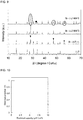
- X-ray diffraction (XRD) measurement was carried out on the LLZ used in Example 1 and the Si-LLZ sintered body produced in Example 1.
- the measurement conditions are as follows.
- FIG. 2 is a view showing a XRD spectrum of the LLZ and that of the Si-LLZ sintered body.
- the XRD spectrum on the upper side is that of the Si-LLZ sintered body
- the XRD spectrum on the lower side is that of the LLZ.
- peaks common to both of the spectra are connected with a dashed line.
- a peak assigned to a silicon crystal is indicated by a black rhombus
- a peak presumed to be assigned to the solid electrolyte interface (SEI) layer is indicated by a white circle.
- SEI solid electrolyte interface
- X-ray diffraction (XRD) measurement was carried out on the LLZ used in Comparative Example 1 and the Si-LLZ laminate produced in Comparative Example 1.
- the measurement conditions are the same as those of Example 1.
- the measurement temperature was changed to room temperature (15 to 30°C), 600°C and 800°C.
- FIG. 9 is a view showing, from down to up, a XRD spectrum of the LLZ, a XRD spectrum of the Si-LLZ laminate at room temperature (Si-LLZ r. t.), a XRD spectrum of the Si-LLZ laminate at a measurement temperature of 600°C (Si-LLZ 600°C), and a XRD spectrum of the Si-LLZ laminate at a measurement temperature of 800°C (Si-LLZ 800°C).
- a black upside-down triangle above the spectrum of the Si-LLZ r. t. corresponds to the peak indicated by the black rhombus shown in FIG. 2 and indicates a peak assigned to a silicon crystal.
- a charge-discharge test of the oxide all-solid-state batteries of Example 1 and Reference Example 1 was carried out in the following conditions.
- impedance measurement was carried out at potentials of 0.3 V, 0.2 V and 0.1 V (vs. Li + /Li).
- Devices and conditions used in the charge-discharge test and impedance measurement are as follows:
- the Si-LLZ laminate is heated at 600°C, the Si turns into SiO 2 (quartz glass) and, as a result, the anode cannot be charged and discharged.
- FIG. 6 is a Nyquist diagram showing the results of the impedance measurement of the oxide all-solid-state battery (symmetric cell) of Reference Example 2.
- the oxide all-solid-state battery of Reference Example 2 is a symmetric cell, there are two possible resistance components: the resistance component of the LLZ and the resistance component of the Li-LLZ interface. It is known that a resistance component of 0.5 MHz or more is the resistance component of the LLZ. Therefore, as a result of considering the measurement results shown in FIG. 6 and the sectional area of the lithium in the symmetric cell, it is clear that the frequency characteristic of the Li-LLZ interface of Reference Example 2 is in a range of from 100 Hz to 0.5 MHz, and the resistance thereof is about 150 ⁇ cm 2 .
- FIG. 7 shows charge and discharge curves of the oxide all-solid-state battery of Reference Example 1.
- solid lines indicate the results of the first charge and discharge
- dashed lines indicate the results of the second charge and discharge.
- FIGS. 8A, 8B and 8C are Nyquist diagrams showing the results of the impedance measurement of the oxide all-solid-state battery of Reference Example 1 at 0.3 V (vs. Li + /Li), 0.2 V (vs. Li + /Li), and 0.1 V (vs. Li + /Li), respectively.
- the resistance component of the LLZ For the oxide all-solid-state battery of Reference Example 1, there are three possible resistance components: the resistance component of the LLZ, the resistance component of the Li-LLZ interface, and the resistance component of the Si-LLZ interface. From the results shown in FIG. 6 , it is clear that a resistance component of 0.5 MHz or more is the resistance component of the LLZ, and a resistance component in a range of from 100 Hz to 0.5 MHz is the resistance component of the Li-LLZ interface. Therefore, the frequency characteristic of the Si-LLZ interface is presumed to be in a range of from 1 to 100 Hz.
- the frequency characteristic of the Li-LLZ interface of Reference Example 1 is in a range of from 1 to 100 Hz, and the resistance thereof is about 150 ⁇ cm 2 .
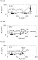
- FIG. 3 shows charge and discharge curves of the oxide all-solid-state battery of Example 1.
- a curve on the lower side indicates a charge curve
- a curve on the upper side indicates a discharge curve
- FIGS. 4A, 4B and 4C are Nyquist diagrams showing the results of the impedance measurement of the oxide all-solid-state battery of Example 1 at 0.3 V (vs. Li + /Li), 0.2 V (vs. Li + /Li) and 0.1 V (vs. Li + /Li), respectively.
- a point of 0.3 V, that of 0.2 V and that of 0.1 V in FIG. 3 correspond to FIG. 4A.
- FIG. 4B and FIG. 4C respectively.
- the oxide all-solid-state battery of Example 1 illustrates almost the same charge and discharge curves as the charge-discharge result of a common silicon anode-liquid electrolyte battery (for example, see FIG. 5(a) provided in J. P. Maranchi et al., Electrochemical and Solid-State Letters. 6 (9) A198-A201 (2003 )). From this fact, the silicon anode obtained by sintering the liquid silicon material is presumed to have the same properties as a commonly-known silicon anode.
- the frequency characteristic of the Si-LLZ interface is in a range of from 1 to 100 Hz. Therefore, from the size of an arc in this range, it is clear that the resistance of the Li-LLZ interface of Example 1 is about 150 ⁇ cm 2 .
- Example 1 As just described, as a result of comparing the results of Example 1 and Reference Example 1, the following is clear: for the oxide all-solid-state battery produced by using the liquid silicon material (Example 1), the interface between the silicon anode and the LLZ has excellent lithium conductivity comparable to the oxide all-solid-state battery produced by using a conventional sputtering method (Reference Example 1).
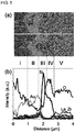
- FIG. 5 shows (a) a SEM image of a section of the oxide all-solid-state battery of Example 1 and (b) a graph showing EDX line analysis results thereof.
- (b) shows the line analysis results of a white line shown in (a) of FIG. 5 , and the horizontal direction of the image (a) corresponds as it is to the horizontal axis of the graph (b).
- curves and the words "Au”, “Si”, “O”, “La” and “Zr” shown in (b) indicate the line analysis results by EDX.
- the region II where Au is relatively largely detected is the anode current collector (gold); the region III where Si is relatively largely detected, is the anode active material layer; and the region V where O, La and Zr are largely detected, is the solid electrolyte layer.
- the region IV where O and Si are relatively largely detected and La and Zr are slightly detected remarkably differs in element ratio from the anode active material layer (the region III) and the solid electrolyte layer (the region V); therefore, the formation of the solid electrolyte interface layer different from these layers, can be confirmed.
- the impedance measurement it is clear that the resistance of the Li-LLZ interface is sufficiently low.
- the charge-discharge measurement it is clear that a battery which can be charged and discharged is obtained.
- EDX line analysis it is clear that atoms lighter than oxygen could not be detected.
- the thickness was calculated from some points shown in (a) of FIG. 5 .
- the average thickness of the anode active material layer (the region III) is 0.6 ⁇ m
- the average thickness of the solid electrolyte interface layer (the region IV) is 0.2 ⁇ m.
- the region I shown in (b) corresponds to shavings produced at the time of battery section processing before the SEM observation.
- the solid electrolyte interface layer can be formed between the anode active material layer and the solid electrolyte layer. Moreover, the joining state of the anode active material layer and the solid electrolyte layer is further enhanced by the solid electrolyte interface layer. It is also clear that due to the presence of the solid electrolyte interface layer, excellent lithium conductivity can be obtained between the anode active material layer and the solid electrolyte layer. In addition, from the excellent lithium conductivity, it is presumed that a lithium element is present in the solid electrolyte interface layer.
Landscapes
- Chemical & Material Sciences (AREA)
- General Chemical & Material Sciences (AREA)
- Engineering & Computer Science (AREA)
- Chemical Kinetics & Catalysis (AREA)
- Electrochemistry (AREA)
- Manufacturing & Machinery (AREA)
- Materials Engineering (AREA)
- Physics & Mathematics (AREA)
- Condensed Matter Physics & Semiconductors (AREA)
- General Physics & Mathematics (AREA)
- Inorganic Chemistry (AREA)
- Secondary Cells (AREA)
- Battery Electrode And Active Subsutance (AREA)
- Conductive Materials (AREA)
Applications Claiming Priority (1)
| Application Number | Priority Date | Filing Date | Title |
|---|---|---|---|
| JP2017035185A JP6662802B2 (ja) | 2017-02-27 | 2017-02-27 | 酸化物全固体電池 |
Publications (2)
| Publication Number | Publication Date |
|---|---|
| EP3376572A1 true EP3376572A1 (de) | 2018-09-19 |
| EP3376572B1 EP3376572B1 (de) | 2019-09-25 |
Family
ID=61256710
Family Applications (1)
| Application Number | Title | Priority Date | Filing Date |
|---|---|---|---|
| EP18157917.8A Active EP3376572B1 (de) | 2017-02-27 | 2018-02-21 | Oxidfeststoffbatterie |
Country Status (5)
| Country | Link |
|---|---|
| US (1) | US10461337B2 (de) |
| EP (1) | EP3376572B1 (de) |
| JP (1) | JP6662802B2 (de) |
| KR (1) | KR102055549B1 (de) |
| CN (1) | CN108511794B (de) |
Cited By (1)
| Publication number | Priority date | Publication date | Assignee | Title |
|---|---|---|---|---|
| EP3813161A1 (de) * | 2019-10-22 | 2021-04-28 | Samsung Electronics Co., Ltd. | Festkörpersekundärbatterie und verfahren zur herstellung einer festkörpersekundärbatterie |
Families Citing this family (18)
| Publication number | Priority date | Publication date | Assignee | Title |
|---|---|---|---|---|
| EP3252024B1 (de) | 2016-05-27 | 2019-12-18 | Toyota Jidosha Kabushiki Kaisha | Oxidelektrolyt-sinterkörper und verfahren zur herstellung davon |
| JP6565950B2 (ja) | 2017-02-02 | 2019-08-28 | トヨタ自動車株式会社 | ガーネット型酸化物固体電解質の製造方法 |
| JP2019046721A (ja) | 2017-09-05 | 2019-03-22 | トヨタ自動車株式会社 | スラリー、固体電解質層の製造方法、及び、全固体電池の製造方法 |
| JP6962094B2 (ja) * | 2017-09-21 | 2021-11-05 | トヨタ自動車株式会社 | ガーネット型イオン伝導性酸化物、及び、酸化物電解質焼結体の製造方法 |
| JP7017079B2 (ja) | 2017-12-28 | 2022-02-08 | トヨタ自動車株式会社 | 電極の製造方法、電極、及び、電極-電解質層接合体 |
| JP6988473B2 (ja) | 2017-12-28 | 2022-01-05 | トヨタ自動車株式会社 | 電池用セパレータ、及び、リチウム電池、並びに、これらの製造方法 |
| JP6988472B2 (ja) | 2017-12-28 | 2022-01-05 | トヨタ自動車株式会社 | 電池 |
| JP7070329B2 (ja) * | 2018-10-25 | 2022-05-18 | トヨタ自動車株式会社 | 全固体電池の製造方法 |
| US11532851B2 (en) * | 2019-11-08 | 2022-12-20 | Enevate Corporation | Si-anode-based semi-solid cells with solid separators |
| JP6873963B2 (ja) * | 2018-11-09 | 2021-05-19 | 株式会社豊田中央研究所 | リチウム電池及び複合構造体の製造方法 |
| CN111977626B (zh) * | 2019-05-24 | 2024-11-01 | 三星电子株式会社 | 固体导体、其制备方法、包括固体导体的固体电解质和包括固体导体的电化学装置 |
| JP7406932B2 (ja) * | 2019-07-16 | 2023-12-28 | 株式会社デンソー | リチウムイオン二次電池の製造方法 |
| JP7384088B2 (ja) | 2019-12-10 | 2023-11-21 | トヨタ自動車株式会社 | ガーネット型固体電解質セパレータ及びその製造方法 |
| US20210175541A1 (en) | 2019-12-10 | 2021-06-10 | Toyota Jidosha Kabushiki Kaisha | Garnet-type solid electrolyte separator and method of producing the same |
| US20230026839A1 (en) * | 2019-12-27 | 2023-01-26 | Showa Denko K.K. | Lithium ion-conductive oxide and use for same |
| EP4001213A1 (de) | 2020-11-13 | 2022-05-25 | Samsung Electronics Co., Ltd. | Oxid, verfahren zur herstellung davon, fester elektrolyt mit dem oxid und elektrochemische vorrichtung mit dem oxid |
| EP4300618A4 (de) * | 2021-02-25 | 2025-08-27 | Canon Kk | Festelektrolyt, aktivmaterialschicht, elektrolytschicht und sekundärbatterie |
| CN114069022A (zh) * | 2021-11-17 | 2022-02-18 | 鄂尔多斯市紫荆创新研究院 | 单节高电压薄膜锂电池 |
Citations (5)
| Publication number | Priority date | Publication date | Assignee | Title |
|---|---|---|---|---|
| JP2000031066A (ja) | 1998-07-10 | 2000-01-28 | Sharp Corp | シリコン膜の形成方法及び太陽電池の製造方法 |
| JP2010159191A (ja) | 2009-01-09 | 2010-07-22 | Japan Science & Technology Agency | 高次シラン組成物、膜付基板の製造方法、電気光学装置および電子デバイス |
| JP2011070939A (ja) * | 2009-09-25 | 2011-04-07 | Toyota Central R&D Labs Inc | 全固体型リチウム二次電池 |
| JP2012018792A (ja) | 2010-07-07 | 2012-01-26 | National Univ Corp Shizuoka Univ | 固体電解質材料およびリチウム電池 |
| WO2017190135A1 (en) * | 2016-04-29 | 2017-11-02 | University Of Maryland, College Park | Metal alloy layers on substrates, methods of making same, and uses thereof |
Family Cites Families (11)
| Publication number | Priority date | Publication date | Assignee | Title |
|---|---|---|---|---|
| JP4728385B2 (ja) * | 2008-12-10 | 2011-07-20 | ナミックス株式会社 | リチウムイオン二次電池、及び、その製造方法 |
| JP5283188B2 (ja) | 2009-09-03 | 2013-09-04 | 日本碍子株式会社 | 全固体二次電池およびその製造方法 |
| WO2012077225A1 (ja) * | 2010-12-10 | 2012-06-14 | トヨタ自動車株式会社 | 電極体および全固体電池 |
| JP5935246B2 (ja) * | 2011-06-24 | 2016-06-15 | ソニー株式会社 | リチウムイオン二次電池、リチウムイオン二次電池用負極、電池パック、電動車両、電力貯蔵システム、電動工具および電子機器 |
| WO2013046443A1 (ja) * | 2011-09-30 | 2013-04-04 | トヨタ自動車株式会社 | 全固体電池およびその製造方法 |
| JP2013187260A (ja) | 2012-03-06 | 2013-09-19 | Japan Science & Technology Agency | アモルファスシリコンの製造方法及びアモルファスシリコンの製造装置 |
| JP6632240B2 (ja) * | 2014-08-12 | 2020-01-22 | 日本特殊陶業株式会社 | リチウムイオン伝導性セラミックス材料及びリチウム電池 |
| US10312501B2 (en) * | 2014-12-10 | 2019-06-04 | GM Global Technology Operations LLC | Electrolyte and negative electrode structure |
| JP2016201310A (ja) * | 2015-04-13 | 2016-12-01 | 株式会社日立製作所 | 全固体リチウム二次電池 |
| JP6488183B2 (ja) * | 2015-04-30 | 2019-03-20 | 富士フイルム株式会社 | 全固体二次電池、全固体二次電池用電極シート、および全固体二次電池の製造方法 |
| CN105098227B (zh) * | 2015-08-22 | 2018-03-16 | 哈尔滨工业大学 | 全固态锂离子电池及其制备方法 |
-
2017
- 2017-02-27 JP JP2017035185A patent/JP6662802B2/ja active Active
-
2018
- 2018-02-21 KR KR1020180020512A patent/KR102055549B1/ko active Active
- 2018-02-21 EP EP18157917.8A patent/EP3376572B1/de active Active
- 2018-02-23 US US15/903,092 patent/US10461337B2/en active Active
- 2018-02-23 CN CN201810154427.5A patent/CN108511794B/zh active Active
Patent Citations (6)
| Publication number | Priority date | Publication date | Assignee | Title |
|---|---|---|---|---|
| JP2000031066A (ja) | 1998-07-10 | 2000-01-28 | Sharp Corp | シリコン膜の形成方法及び太陽電池の製造方法 |
| JP2010159191A (ja) | 2009-01-09 | 2010-07-22 | Japan Science & Technology Agency | 高次シラン組成物、膜付基板の製造方法、電気光学装置および電子デバイス |
| JP2011070939A (ja) * | 2009-09-25 | 2011-04-07 | Toyota Central R&D Labs Inc | 全固体型リチウム二次電池 |
| JP2012018792A (ja) | 2010-07-07 | 2012-01-26 | National Univ Corp Shizuoka Univ | 固体電解質材料およびリチウム電池 |
| US20130084505A1 (en) * | 2010-07-07 | 2013-04-04 | Toyota Jidosha Kabushiki Kaisha | Solid electrolyte material and lithium battery |
| WO2017190135A1 (en) * | 2016-04-29 | 2017-11-02 | University Of Maryland, College Park | Metal alloy layers on substrates, methods of making same, and uses thereof |
Non-Patent Citations (1)
| Title |
|---|
| J. P. MARANCHI ET AL., ELECTROCHEMICAL AND SOLID-STATE LETTERS, vol. 6, no. 9, 2003, pages A198 - A201 |
Cited By (1)
| Publication number | Priority date | Publication date | Assignee | Title |
|---|---|---|---|---|
| EP3813161A1 (de) * | 2019-10-22 | 2021-04-28 | Samsung Electronics Co., Ltd. | Festkörpersekundärbatterie und verfahren zur herstellung einer festkörpersekundärbatterie |
Also Published As
| Publication number | Publication date |
|---|---|
| EP3376572B1 (de) | 2019-09-25 |
| CN108511794A (zh) | 2018-09-07 |
| KR102055549B1 (ko) | 2019-12-13 |
| US10461337B2 (en) | 2019-10-29 |
| CN108511794B (zh) | 2021-04-13 |
| JP2018142432A (ja) | 2018-09-13 |
| JP6662802B2 (ja) | 2020-03-11 |
| US20180248201A1 (en) | 2018-08-30 |
| KR20180099491A (ko) | 2018-09-05 |
Similar Documents
| Publication | Publication Date | Title |
|---|---|---|
| EP3376572B1 (de) | Oxidfeststoffbatterie | |
| EP3540825B1 (de) | Lithiumsekundärbatterie | |
| CN110739451B (zh) | 锂二次电池用正极活性物质、锂二次电池用正极和锂二次电池 | |
| JP6163294B2 (ja) | リチウム二次電池 | |
| KR101038637B1 (ko) | 음극 활성 물질, 그것을 이용한 음극, 그것을 이용한비수성 전해질 전지, 및 음극 활성 물질의 제조 방법 | |
| EP3096375B1 (de) | Lithium-luft batterie und verfahren zu deren herstellung | |
| CN110692154B (zh) | 锂二次电池用正极活性物质、锂二次电池用正极以及锂二次电池 | |
| CN111971254B (zh) | 锂复合金属氧化物、锂二次电池用正极活性物质、锂二次电池用正极以及锂二次电池 | |
| KR20210150399A (ko) | 리튬 금속 복합 산화물 분말 및 리튬 이차 전지용 정극 활물질 | |
| KR102769409B1 (ko) | 리튬 이차 전지 정극 활물질용 전구체, 리튬 이차 전지 정극 활물질용 전구체의 제조 방법 및 리튬 복합 금속 화합물의 제조 방법 | |
| US20160079597A1 (en) | All-solid lithium ion secondary battery | |
| US12261266B2 (en) | Nanofiber polymer composite cathodes | |
| WO2016060105A1 (ja) | リチウム二次電池用正極活物質、リチウム二次電池用正極及びリチウム二次電池 | |
| EP2916375B1 (de) | Negatives Aktivmaterial, negative Elektrode und Lithiumbatterie mit dem negativen Aktivmaterial und Verfahren zur Herstellung des negativen Aktivmaterials | |
| KR20190132633A (ko) | 리튬니켈 복합 산화물의 제조 방법 | |
| EP3783708A1 (de) | Kathodenaktivmaterial für eine lithiumsekundärbatterie sowie lithiumsekundärbatterie damit | |
| EP3800713A1 (de) | Aktives kathodenmaterial für lithiumsekundärbatterie und lithiumsekundärbatterie | |
| US5698338A (en) | Solid secondary lithium cell based on Lix Niy Co1-y VO4< or=x< or=1.1 and 0<y<1 cathode material | |
| EP3151313A1 (de) | Negatives aktivmaterial und negativelektrode und lithiumbatterie mit dem material | |
| Koike et al. | Preparation and performances of highly porous layered LiCoO2 films for lithium batteries | |
| EP4393017A1 (de) | Elektrodenbeschichtungsverfahren und beschichtete elektrode | |
| KR102234705B1 (ko) | 복합음극활물질, 이를 채용한 음극과 리튬전지 및 그 제조방법 | |
| EP3649082B1 (de) | Neue lithium mischmetallsulfid mit hoher ionenleitfähigkeit | |
| Takai et al. | Improved cathode performance and relaxation properties of LiMn2O4 prepared by optimized ball-milling with single-step sintering |
Legal Events
| Date | Code | Title | Description |
|---|---|---|---|
| PUAI | Public reference made under article 153(3) epc to a published international application that has entered the european phase |
Free format text: ORIGINAL CODE: 0009012 |
|
| STAA | Information on the status of an ep patent application or granted ep patent |
Free format text: STATUS: REQUEST FOR EXAMINATION WAS MADE |
|
| 17P | Request for examination filed |
Effective date: 20180221 |
|
| AK | Designated contracting states |
Kind code of ref document: A1 Designated state(s): AL AT BE BG CH CY CZ DE DK EE ES FI FR GB GR HR HU IE IS IT LI LT LU LV MC MK MT NL NO PL PT RO RS SE SI SK SM TR |
|
| AX | Request for extension of the european patent |
Extension state: BA ME |
|
| REG | Reference to a national code |
Ref country code: DE Ref legal event code: R079 Ref document number: 602018000707 Country of ref document: DE Free format text: PREVIOUS MAIN CLASS: H01M0004380000 Ipc: H01M0006180000 |
|
| GRAP | Despatch of communication of intention to grant a patent |
Free format text: ORIGINAL CODE: EPIDOSNIGR1 |
|
| STAA | Information on the status of an ep patent application or granted ep patent |
Free format text: STATUS: GRANT OF PATENT IS INTENDED |
|
| RIC1 | Information provided on ipc code assigned before grant |
Ipc: H01M 4/134 20100101ALI20190418BHEP Ipc: H01M 4/04 20060101ALI20190418BHEP Ipc: H01M 4/38 20060101ALI20190418BHEP Ipc: H01M 10/0562 20100101ALI20190418BHEP Ipc: H01M 4/1395 20100101ALI20190418BHEP Ipc: H01M 6/18 20060101AFI20190418BHEP Ipc: H01M 10/052 20100101ALI20190418BHEP Ipc: H01M 10/058 20100101ALI20190418BHEP |
|
| INTG | Intention to grant announced |
Effective date: 20190517 |
|
| GRAS | Grant fee paid |
Free format text: ORIGINAL CODE: EPIDOSNIGR3 |
|
| GRAA | (expected) grant |
Free format text: ORIGINAL CODE: 0009210 |
|
| STAA | Information on the status of an ep patent application or granted ep patent |
Free format text: STATUS: THE PATENT HAS BEEN GRANTED |
|
| AK | Designated contracting states |
Kind code of ref document: B1 Designated state(s): AL AT BE BG CH CY CZ DE DK EE ES FI FR GB GR HR HU IE IS IT LI LT LU LV MC MK MT NL NO PL PT RO RS SE SI SK SM TR |
|
| REG | Reference to a national code |
Ref country code: GB Ref legal event code: FG4D |
|
| REG | Reference to a national code |
Ref country code: CH Ref legal event code: EP |
|
| REG | Reference to a national code |
Ref country code: AT Ref legal event code: REF Ref document number: 1184720 Country of ref document: AT Kind code of ref document: T Effective date: 20191015 |
|
| REG | Reference to a national code |
Ref country code: IE Ref legal event code: FG4D |
|
| REG | Reference to a national code |
Ref country code: DE Ref legal event code: R096 Ref document number: 602018000707 Country of ref document: DE |
|
| REG | Reference to a national code |
Ref country code: NL Ref legal event code: MP Effective date: 20190925 |
|
| PG25 | Lapsed in a contracting state [announced via postgrant information from national office to epo] |
Ref country code: LT Free format text: LAPSE BECAUSE OF FAILURE TO SUBMIT A TRANSLATION OF THE DESCRIPTION OR TO PAY THE FEE WITHIN THE PRESCRIBED TIME-LIMIT Effective date: 20190925 Ref country code: BG Free format text: LAPSE BECAUSE OF FAILURE TO SUBMIT A TRANSLATION OF THE DESCRIPTION OR TO PAY THE FEE WITHIN THE PRESCRIBED TIME-LIMIT Effective date: 20191225 Ref country code: FI Free format text: LAPSE BECAUSE OF FAILURE TO SUBMIT A TRANSLATION OF THE DESCRIPTION OR TO PAY THE FEE WITHIN THE PRESCRIBED TIME-LIMIT Effective date: 20190925 Ref country code: NO Free format text: LAPSE BECAUSE OF FAILURE TO SUBMIT A TRANSLATION OF THE DESCRIPTION OR TO PAY THE FEE WITHIN THE PRESCRIBED TIME-LIMIT Effective date: 20191225 Ref country code: SE Free format text: LAPSE BECAUSE OF FAILURE TO SUBMIT A TRANSLATION OF THE DESCRIPTION OR TO PAY THE FEE WITHIN THE PRESCRIBED TIME-LIMIT Effective date: 20190925 Ref country code: HR Free format text: LAPSE BECAUSE OF FAILURE TO SUBMIT A TRANSLATION OF THE DESCRIPTION OR TO PAY THE FEE WITHIN THE PRESCRIBED TIME-LIMIT Effective date: 20190925 |
|
| REG | Reference to a national code |
Ref country code: LT Ref legal event code: MG4D |
|
| PG25 | Lapsed in a contracting state [announced via postgrant information from national office to epo] |
Ref country code: LV Free format text: LAPSE BECAUSE OF FAILURE TO SUBMIT A TRANSLATION OF THE DESCRIPTION OR TO PAY THE FEE WITHIN THE PRESCRIBED TIME-LIMIT Effective date: 20190925 Ref country code: GR Free format text: LAPSE BECAUSE OF FAILURE TO SUBMIT A TRANSLATION OF THE DESCRIPTION OR TO PAY THE FEE WITHIN THE PRESCRIBED TIME-LIMIT Effective date: 20191226 Ref country code: RS Free format text: LAPSE BECAUSE OF FAILURE TO SUBMIT A TRANSLATION OF THE DESCRIPTION OR TO PAY THE FEE WITHIN THE PRESCRIBED TIME-LIMIT Effective date: 20190925 |
|
| REG | Reference to a national code |
Ref country code: AT Ref legal event code: MK05 Ref document number: 1184720 Country of ref document: AT Kind code of ref document: T Effective date: 20190925 |
|
| PG25 | Lapsed in a contracting state [announced via postgrant information from national office to epo] |
Ref country code: EE Free format text: LAPSE BECAUSE OF FAILURE TO SUBMIT A TRANSLATION OF THE DESCRIPTION OR TO PAY THE FEE WITHIN THE PRESCRIBED TIME-LIMIT Effective date: 20190925 Ref country code: RO Free format text: LAPSE BECAUSE OF FAILURE TO SUBMIT A TRANSLATION OF THE DESCRIPTION OR TO PAY THE FEE WITHIN THE PRESCRIBED TIME-LIMIT Effective date: 20190925 Ref country code: IT Free format text: LAPSE BECAUSE OF FAILURE TO SUBMIT A TRANSLATION OF THE DESCRIPTION OR TO PAY THE FEE WITHIN THE PRESCRIBED TIME-LIMIT Effective date: 20190925 Ref country code: PL Free format text: LAPSE BECAUSE OF FAILURE TO SUBMIT A TRANSLATION OF THE DESCRIPTION OR TO PAY THE FEE WITHIN THE PRESCRIBED TIME-LIMIT Effective date: 20190925 Ref country code: PT Free format text: LAPSE BECAUSE OF FAILURE TO SUBMIT A TRANSLATION OF THE DESCRIPTION OR TO PAY THE FEE WITHIN THE PRESCRIBED TIME-LIMIT Effective date: 20200127 Ref country code: AL Free format text: LAPSE BECAUSE OF FAILURE TO SUBMIT A TRANSLATION OF THE DESCRIPTION OR TO PAY THE FEE WITHIN THE PRESCRIBED TIME-LIMIT Effective date: 20190925 Ref country code: ES Free format text: LAPSE BECAUSE OF FAILURE TO SUBMIT A TRANSLATION OF THE DESCRIPTION OR TO PAY THE FEE WITHIN THE PRESCRIBED TIME-LIMIT Effective date: 20190925 Ref country code: NL Free format text: LAPSE BECAUSE OF FAILURE TO SUBMIT A TRANSLATION OF THE DESCRIPTION OR TO PAY THE FEE WITHIN THE PRESCRIBED TIME-LIMIT Effective date: 20190925 Ref country code: AT Free format text: LAPSE BECAUSE OF FAILURE TO SUBMIT A TRANSLATION OF THE DESCRIPTION OR TO PAY THE FEE WITHIN THE PRESCRIBED TIME-LIMIT Effective date: 20190925 |
|
| PG25 | Lapsed in a contracting state [announced via postgrant information from national office to epo] |
Ref country code: SK Free format text: LAPSE BECAUSE OF FAILURE TO SUBMIT A TRANSLATION OF THE DESCRIPTION OR TO PAY THE FEE WITHIN THE PRESCRIBED TIME-LIMIT Effective date: 20190925 Ref country code: IS Free format text: LAPSE BECAUSE OF FAILURE TO SUBMIT A TRANSLATION OF THE DESCRIPTION OR TO PAY THE FEE WITHIN THE PRESCRIBED TIME-LIMIT Effective date: 20200224 Ref country code: CZ Free format text: LAPSE BECAUSE OF FAILURE TO SUBMIT A TRANSLATION OF THE DESCRIPTION OR TO PAY THE FEE WITHIN THE PRESCRIBED TIME-LIMIT Effective date: 20190925 Ref country code: SM Free format text: LAPSE BECAUSE OF FAILURE TO SUBMIT A TRANSLATION OF THE DESCRIPTION OR TO PAY THE FEE WITHIN THE PRESCRIBED TIME-LIMIT Effective date: 20190925 |
|
| REG | Reference to a national code |
Ref country code: DE Ref legal event code: R097 Ref document number: 602018000707 Country of ref document: DE |
|
| PG2D | Information on lapse in contracting state deleted |
Ref country code: IS |
|
| PG25 | Lapsed in a contracting state [announced via postgrant information from national office to epo] |
Ref country code: IS Free format text: LAPSE BECAUSE OF FAILURE TO SUBMIT A TRANSLATION OF THE DESCRIPTION OR TO PAY THE FEE WITHIN THE PRESCRIBED TIME-LIMIT Effective date: 20200126 Ref country code: DK Free format text: LAPSE BECAUSE OF FAILURE TO SUBMIT A TRANSLATION OF THE DESCRIPTION OR TO PAY THE FEE WITHIN THE PRESCRIBED TIME-LIMIT Effective date: 20190925 |
|
| PLBE | No opposition filed within time limit |
Free format text: ORIGINAL CODE: 0009261 |
|
| STAA | Information on the status of an ep patent application or granted ep patent |
Free format text: STATUS: NO OPPOSITION FILED WITHIN TIME LIMIT |
|
| 26N | No opposition filed |
Effective date: 20200626 |
|
| REG | Reference to a national code |
Ref country code: BE Ref legal event code: MM Effective date: 20200229 |
|
| PG25 | Lapsed in a contracting state [announced via postgrant information from national office to epo] |
Ref country code: MC Free format text: LAPSE BECAUSE OF FAILURE TO SUBMIT A TRANSLATION OF THE DESCRIPTION OR TO PAY THE FEE WITHIN THE PRESCRIBED TIME-LIMIT Effective date: 20190925 Ref country code: LU Free format text: LAPSE BECAUSE OF NON-PAYMENT OF DUE FEES Effective date: 20200221 |
|
| PG25 | Lapsed in a contracting state [announced via postgrant information from national office to epo] |
Ref country code: SI Free format text: LAPSE BECAUSE OF FAILURE TO SUBMIT A TRANSLATION OF THE DESCRIPTION OR TO PAY THE FEE WITHIN THE PRESCRIBED TIME-LIMIT Effective date: 20190925 |
|
| PG25 | Lapsed in a contracting state [announced via postgrant information from national office to epo] |
Ref country code: IE Free format text: LAPSE BECAUSE OF NON-PAYMENT OF DUE FEES Effective date: 20200221 |
|
| PG25 | Lapsed in a contracting state [announced via postgrant information from national office to epo] |
Ref country code: BE Free format text: LAPSE BECAUSE OF NON-PAYMENT OF DUE FEES Effective date: 20200229 |
|
| REG | Reference to a national code |
Ref country code: DE Ref legal event code: R084 Ref document number: 602018000707 Country of ref document: DE |
|
| PG25 | Lapsed in a contracting state [announced via postgrant information from national office to epo] |
Ref country code: LI Free format text: LAPSE BECAUSE OF NON-PAYMENT OF DUE FEES Effective date: 20210228 Ref country code: CH Free format text: LAPSE BECAUSE OF NON-PAYMENT OF DUE FEES Effective date: 20210228 |
|
| REG | Reference to a national code |
Ref country code: GB Ref legal event code: 746 Effective date: 20220124 |
|
| PG25 | Lapsed in a contracting state [announced via postgrant information from national office to epo] |
Ref country code: TR Free format text: LAPSE BECAUSE OF FAILURE TO SUBMIT A TRANSLATION OF THE DESCRIPTION OR TO PAY THE FEE WITHIN THE PRESCRIBED TIME-LIMIT Effective date: 20190925 Ref country code: MT Free format text: LAPSE BECAUSE OF FAILURE TO SUBMIT A TRANSLATION OF THE DESCRIPTION OR TO PAY THE FEE WITHIN THE PRESCRIBED TIME-LIMIT Effective date: 20190925 Ref country code: CY Free format text: LAPSE BECAUSE OF FAILURE TO SUBMIT A TRANSLATION OF THE DESCRIPTION OR TO PAY THE FEE WITHIN THE PRESCRIBED TIME-LIMIT Effective date: 20190925 |
|
| PG25 | Lapsed in a contracting state [announced via postgrant information from national office to epo] |
Ref country code: MK Free format text: LAPSE BECAUSE OF FAILURE TO SUBMIT A TRANSLATION OF THE DESCRIPTION OR TO PAY THE FEE WITHIN THE PRESCRIBED TIME-LIMIT Effective date: 20190925 |
|
| PGFP | Annual fee paid to national office [announced via postgrant information from national office to epo] |
Ref country code: FR Payment date: 20251231 Year of fee payment: 9 |
|
| PGFP | Annual fee paid to national office [announced via postgrant information from national office to epo] |
Ref country code: GB Payment date: 20260106 Year of fee payment: 9 |
|
| PGFP | Annual fee paid to national office [announced via postgrant information from national office to epo] |
Ref country code: DE Payment date: 20251230 Year of fee payment: 9 |