EP3376128B1 - Steuerungsstruktur einer klimaanlage und steuerungsverfahren dafür - Google Patents
Steuerungsstruktur einer klimaanlage und steuerungsverfahren dafür Download PDFInfo
- Publication number
- EP3376128B1 EP3376128B1 EP18160581.7A EP18160581A EP3376128B1 EP 3376128 B1 EP3376128 B1 EP 3376128B1 EP 18160581 A EP18160581 A EP 18160581A EP 3376128 B1 EP3376128 B1 EP 3376128B1
- Authority
- EP
- European Patent Office
- Prior art keywords
- frequency conversion
- conversion modular
- modular units
- frequency
- load
- Prior art date
- Legal status (The legal status is an assumption and is not a legal conclusion. Google has not performed a legal analysis and makes no representation as to the accuracy of the status listed.)
- Active
Links
Images


Classifications
-
- F—MECHANICAL ENGINEERING; LIGHTING; HEATING; WEAPONS; BLASTING
- F24—HEATING; RANGES; VENTILATING
- F24F—AIR-CONDITIONING; AIR-HUMIDIFICATION; VENTILATION; USE OF AIR CURRENTS FOR SCREENING
- F24F11/00—Control or safety arrangements
- F24F11/62—Control or safety arrangements characterised by the type of control or by internal processing, e.g. using fuzzy logic, adaptive control or estimation of values
- F24F11/63—Electronic processing
- F24F11/65—Electronic processing for selecting an operating mode
-
- F—MECHANICAL ENGINEERING; LIGHTING; HEATING; WEAPONS; BLASTING
- F25—REFRIGERATION OR COOLING; COMBINED HEATING AND REFRIGERATION SYSTEMS; HEAT PUMP SYSTEMS; MANUFACTURE OR STORAGE OF ICE; LIQUEFACTION SOLIDIFICATION OF GASES
- F25B—REFRIGERATION MACHINES, PLANTS OR SYSTEMS; COMBINED HEATING AND REFRIGERATION SYSTEMS; HEAT PUMP SYSTEMS
- F25B49/00—Arrangement or mounting of control or safety devices
- F25B49/02—Arrangement or mounting of control or safety devices for compression type machines, plants or systems
- F25B49/022—Compressor control arrangements
-
- F—MECHANICAL ENGINEERING; LIGHTING; HEATING; WEAPONS; BLASTING
- F24—HEATING; RANGES; VENTILATING
- F24F—AIR-CONDITIONING; AIR-HUMIDIFICATION; VENTILATION; USE OF AIR CURRENTS FOR SCREENING
- F24F11/00—Control or safety arrangements
- F24F11/30—Control or safety arrangements for purposes related to the operation of the system, e.g. for safety or monitoring
- F24F11/46—Improving electric energy efficiency or saving
-
- F—MECHANICAL ENGINEERING; LIGHTING; HEATING; WEAPONS; BLASTING
- F24—HEATING; RANGES; VENTILATING
- F24F—AIR-CONDITIONING; AIR-HUMIDIFICATION; VENTILATION; USE OF AIR CURRENTS FOR SCREENING
- F24F11/00—Control or safety arrangements
- F24F11/50—Control or safety arrangements characterised by user interfaces or communication
- F24F11/54—Control or safety arrangements characterised by user interfaces or communication using one central controller connected to several sub-controllers
-
- F—MECHANICAL ENGINEERING; LIGHTING; HEATING; WEAPONS; BLASTING
- F24—HEATING; RANGES; VENTILATING
- F24F—AIR-CONDITIONING; AIR-HUMIDIFICATION; VENTILATION; USE OF AIR CURRENTS FOR SCREENING
- F24F11/00—Control or safety arrangements
- F24F11/70—Control systems characterised by their outputs; Constructional details thereof
- F24F11/80—Control systems characterised by their outputs; Constructional details thereof for controlling the temperature of the supplied air
- F24F11/86—Control systems characterised by their outputs; Constructional details thereof for controlling the temperature of the supplied air by controlling compressors within refrigeration or heat pump circuits
-
- G—PHYSICS
- G05—CONTROLLING; REGULATING
- G05B—CONTROL OR REGULATING SYSTEMS IN GENERAL; FUNCTIONAL ELEMENTS OF SUCH SYSTEMS; MONITORING OR TESTING ARRANGEMENTS FOR SUCH SYSTEMS OR ELEMENTS
- G05B15/00—Systems controlled by a computer
- G05B15/02—Systems controlled by a computer electric
-
- F—MECHANICAL ENGINEERING; LIGHTING; HEATING; WEAPONS; BLASTING
- F24—HEATING; RANGES; VENTILATING
- F24F—AIR-CONDITIONING; AIR-HUMIDIFICATION; VENTILATION; USE OF AIR CURRENTS FOR SCREENING
- F24F2110/00—Control inputs relating to air properties
- F24F2110/10—Temperature
-
- F—MECHANICAL ENGINEERING; LIGHTING; HEATING; WEAPONS; BLASTING
- F24—HEATING; RANGES; VENTILATING
- F24F—AIR-CONDITIONING; AIR-HUMIDIFICATION; VENTILATION; USE OF AIR CURRENTS FOR SCREENING
- F24F2140/00—Control inputs relating to system states
- F24F2140/20—Heat-exchange fluid temperature
-
- F—MECHANICAL ENGINEERING; LIGHTING; HEATING; WEAPONS; BLASTING
- F24—HEATING; RANGES; VENTILATING
- F24F—AIR-CONDITIONING; AIR-HUMIDIFICATION; VENTILATION; USE OF AIR CURRENTS FOR SCREENING
- F24F2140/00—Control inputs relating to system states
- F24F2140/50—Load
-
- F—MECHANICAL ENGINEERING; LIGHTING; HEATING; WEAPONS; BLASTING
- F25—REFRIGERATION OR COOLING; COMBINED HEATING AND REFRIGERATION SYSTEMS; HEAT PUMP SYSTEMS; MANUFACTURE OR STORAGE OF ICE; LIQUEFACTION SOLIDIFICATION OF GASES
- F25B—REFRIGERATION MACHINES, PLANTS OR SYSTEMS; COMBINED HEATING AND REFRIGERATION SYSTEMS; HEAT PUMP SYSTEMS
- F25B2600/00—Control issues
- F25B2600/02—Compressor control
- F25B2600/021—Inverters therefor
-
- F—MECHANICAL ENGINEERING; LIGHTING; HEATING; WEAPONS; BLASTING
- F25—REFRIGERATION OR COOLING; COMBINED HEATING AND REFRIGERATION SYSTEMS; HEAT PUMP SYSTEMS; MANUFACTURE OR STORAGE OF ICE; LIQUEFACTION SOLIDIFICATION OF GASES
- F25B—REFRIGERATION MACHINES, PLANTS OR SYSTEMS; COMBINED HEATING AND REFRIGERATION SYSTEMS; HEAT PUMP SYSTEMS
- F25B2600/00—Control issues
- F25B2600/02—Compressor control
- F25B2600/025—Compressor control by controlling speed
- F25B2600/0251—Compressor control by controlling speed with on-off operation
Definitions
- the present disclosure relates to an air-conditioning system having modular air-cooled water-cooled chillers (heat pumps), and more particularly to a structure and a method for adjusting and controlling energy of a full-frequency-conversion modular air-cooled water-cooled chiller (heat pump) set in an air-conditioning system.
- modular set As a large-capacity air-conditioning unit combined by a plurality of small-capacity air- cooled water-cooled chiller (heat pump) sets, has advantages like flexibility, convenience, energy-conservation, and reliability.
- Conventional modular sets basically employ an invariable-frequency compressor; in practical use, such modular sets have disadvantages such as frequent start/ stop and large fluctuation of water temperature. With increasingly higher demands on energy conservation and wider application of frequency-conversion technologies, it will be a trend for modular sets to use frequency-conversion compressors.
- compressor load/unload are controlled based on a difference between a water temperature and a target temperature as well as a water temperature change trend; the consequence is that the compressor will frequently start/stop, which causes a waste in electrical energy and a large water temperature fluctuation. If a similar approach is still employed after the modular set employs a frequency conversion system, the frequency changer set cannot exert its advantages.
- US 2012/174609 A1 relates to a conventional heat source system including a plurality of heat source apparatuses connected in parallel, and a number-of-units control device that controls on and off of the plurality of the heat source apparatuses and allocates a load to an active heat source apparatus according to a load demand, wherein the heat source apparatuses each possess a coefficient of performance, COP, map unique to the respective heat source apparatuses that indicates a relationship between a operating status, a COP , and load factor, each of the heat source apparatuses sets the appropriate operation region in correspondence to the operating status from the COP map and sends it to the number-of-units control device, and the number-of-units control device performs number-of-units control of the heat source apparatuses and load allocation on the basis of the appropriate operating region that is sent from each of the heat source apparatuses.
- the heat source apparatuses each possess a coefficient of performance, COP, map unique to the respective heat source apparatuses that indicates a relationship between a
- Fig. 1 is a schematic structural diagram of an air-conditioning system 100 of the present disclosure.
- the air-conditioning system 100 comprises a frequency conversion modular set 102, an indoor unit set 104, and a floor heating apparatus 106.
- the frequency conversion modular set 102 comprises a plurality of frequency conversion modular units (112.1, 112.2, ..., 112.N); each frequency conversion modular unit includes a compressor, a condenser, an expansion valve, and an evaporator (not shown).
- each frequency conversion modular unit includes a compressor, a condenser, an expansion valve, and an evaporator (not shown).
- a high-temperature high-pressure gaseous cooling medium discharged from the compressor exchanges heat with an environment medium in the condenser, the released heat being liquified and condensed
- the expansion valve throttles the high-pressure liquid cooling medium from the condenser so as to lower its pressure
- the low pressure cooling medium exchanges heat with an object to be cooled inside the evaporator and absorb the heat from the object to be cooled, and become gasified and then evaporated
- the gasified cooling medium steam is drawn in by the compressor, compressed and discharged in high pressure.
- one side of the evaporator is connected with the cooling medium, and the other side of the evaporator is connected with a frequency conversion modular set water pipe 110.
- corresponding increase or decrease of the compressor frequency can correspondingly increase or decrease a rotary speed of the compressor, thereby increasing or decreasing cooling medium flow rate outputted by the compressor, while increase or decrease of the refrigerant flow may increase or decrease a temperature output energy.
- adjustment of the temperature output energy is implemented by adjusting the loading frequency of the compressor.
- the indoor unit set 104 comprises a plurality of indoor units (122.1, 122.2, ..., 122.M), an energy receiving end of each indoor unit being connected with a frequency conversion modular set water pipe 110 to receive a temperature source from the frequency conversion modular set 102, while a control end thereof is connected with controllers (124.1, 124.2, ..., 124.M). Each controller controls the water flow rate and wind speed of a corresponding indoor unit, thereby controlling the indoor temperature.
- the function of the floor heating unit is to raise an air temperature within a certain indoor area by using the heating function provided by the frequency conversion modular set 102.
- the floor heating apparatus 106 comprises a plurality of floor heating units (132.1, 132.2, ..., 132.K) each floor heating unit being connected with the frequency conversion modular set water pipe 110 via its water pipe and a distribution manifold 136 to receive a temperature source from the frequency conversion modular set 102, while a control end thereof is connected with the controllers (134.1, 134.2, ..., 134.K). Each controller controls the water flow rate of the corresponding floor heating unit, thereby controlling the indoor temperature.
- a main controller 118.1 is provided in the main unit 112.1, and controllers (118.2, ..., 118.N) are provided in respective slave units (1, ..., N-1); the main controller 118.1 is in communicative connection with the controllers (118.2, ..., 118.N) in all slave units (1, ..., N-1) such that the main controller 118.1 receives an operating state of the compressor (e.g., a current operating frequency of the compressor) from the controllers (118.2, ..., 118.N) in the slave units (1, ..., N-1), detects signals and transmits a control signal for adjusting the operating state of its compressor (e.g., adjusting the current operating frequency of the compressor) to the controllers (118.2, ..., 118.N) in all slave units (1, ..., N-1).
- an operating state of the compressor e.g., a current operating frequency of the compressor
- a water temperature sensor 108 is provided for detecting a current temperature of water entering/exiting the water pipe connected with the main unit 112.1, the current temperature of the water entering/exiting the water pipe connected with the main unit 112.1 being used as a current temperature TW of the water entering/exiting the set in the air-conditioning system 100.
- the energy efficiency profile forms like an inverse parabola 202; when the load ratio is t, the energy efficiency of each frequency conversion modular unit reaches a maximum value, i.e., COP Max.
- the energy efficiency COP Acc in the ordinate represents an acceptable load point of the energy efficiency for each frequency conversion modular unit.
- An optimized interval (a, b) is provided within the load interval (s, s') so as to cause the plurality of frequency conversion modular units (112.1, 112.2, ..., 112.N) to operate in a more optimized manner within the load interval (s, s'), wherein a denotes a shutdown point of the frequency conversion modular units, and b denotes a start point of the frequency conversion modular units.
- Setting of the optimized range (a, b) causes each frequency conversion modular unit to operate with an energy efficiency as close as possible to point t.
- the abscissa, theordinate, and the function curve change shown in Fig. 2 show a model of performing frequency load and frequency unload to each frequency conversion modular unit according to the present disclosure.
- the frequency conversion modular set 102 has different set energy efficiencies under different loads; there will be an acme between the low load and the high load; an objective of load/unload of the frequency conversion modular set 102 is to cause the set to operate under the high energy efficiency point or as close as possible to the high energy efficiency point;
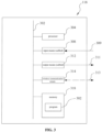
- the memory 318 is arranged for storing programs, instructions, and data, while the processor 304 reads programs, instructions, and data from the memory 318 and may write data to the memory 318.
- the processor 304 controls operations of the input means (cabled) 308, the output means (cabled) 312, and the wireless communication means 314.
- the programs that implement the flow charts shown in Figs. 4 ⁇ 12 are stored in the memory 318 of the main controller 118.
- the main controller 118 controls the frequency conversion modular units (112.1, 112.2, ..., 112.N).
- the memory 318 also stores the target water temperature and the current temperature, wherein the target water temperature is represented by the symbol Tw.target, and the current temperature is represented by the symbol Tw.
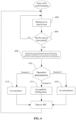
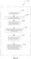
- Fig. 4 is a control flow chart showing the procedures the main controller 118 controls the frequency conversion modular units (112.1, 112.2, ..., 112.N).
- step 402 the processor 304 waits for an interval time.
- step 404 the processor 304 determines whether the interval time expires. If the interval time has not expired yet, the processor 304 will return operation to step 402; upon expiration of the interval time, the processor 304 make operation jump to step 408.
- the target water temperature Tw.target is a set value inputted to the processor 304, while the current temperature Tw is detected by the water temperature sensor 108.
- the target water temperature Tw.target may be ranged between 5 ⁇ 20°C.
- the water temperature sensor 108 provides the detected current temperature Tw to the processor 304; after receiving the temperature Tw, the processor 304 stores it in the memory 318.
- the water temperature sensor 108 measures the current temperature Tw of the water in the water pipe by using temperature conduction of water.
- the water temperature sensor 108 may be placed in the water to contact with the water, thereby measuring the current temperature Tw of the water in the water pipe.
- the energy adjustment amount is represented by a percentage of a adjustment load ratio corresponding to the energy adjustment amount to the total load ratio of the frequency conversion modular set 102; while the energy adjustment amount of each frequency conversion modular unit is represented by a percentage of the adjustment load ratio corresponding to the energy adjustment amount of each frequency conversion modular unit to the total load ratio of the frequency conversion modular units.
- step 410 the processor 304 performs operation determination, and the control procedure turns to corresponding set load phase 412, set unload phase 416, or set capacity holding phase 414, respectively, according to three different scenarios, i.e., scenario 1, scenario 2, or scenario 3.
- the load ratio or the unload ratio is represented by a percentage of the adjustment load ratio to the total load ratio of the frequency conversion modular set 102; while the load ratio and the unload ratio of each frequency conversion modular unit are represented by a percentage of the adjustment load ratio of the frequency conversion modular unit to the total load ratio of the frequency conversion modular unit.
- step 412 The function of step 412 is: (1) applying frequency load to the selected (or already operating) frequency conversion modular units in the frequency conversion modular set 102, or (2) starting a unactuated frequency conversion modular unit, and applying frequency load or frequency unload to the selected frequency conversion modular units (including the just started frequency conversion modular unit and the operating frequency conversion modular units), dependent on whether a newly calculated average operating frequency is greater than or smaller than the current operating frequency. If the newly calculated average operating frequency is greater than the current operating frequency, frequency load is applied to the selected frequency conversion modular units in step 412; if the average operating frequency is smaller than the current operating frequency, frequency unload is applied to the selected frequency conversion modular units in step 412.
- step 416 The function of step 416 is: (1) applying unload to the selected (already operating) frequency conversion modular units in the frequency conversion modular set 102, or (2) unloading an already operating frequency conversion modular unit and applying frequency load or frequency unload to the selected (not including the just unloaded frequency conversion modular unit) operating frequency conversion modular units, dependent on whether the newly calculated average operating frequency is greater than the current operating frequency or lower than the current operating frequency. If the newly calculated average operating frequency is greater than the current operating frequency, the frequency load is applied to the selected frequency conversion modular units load in step 412; if the average operating frequency is smaller than the current operating frequency, frequency unload is applied to the selected frequency conversion modular units in step 412.
- step 412, 414 or 416 the processor 304 makes operation jump to step 402. After waiting for a periodic interval time, a next period of adjustment is performed so as to repeat the operations shown in Fig. 4 .
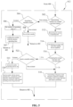
- Fig. 5 shows more detailed steps of the set load procedure in step 412.
- step 502 the processor 304 determines whether any frequency conversion modular unit has been started; if none of the frequency conversion modular unit has been started, the processor 304 makes operation jump to step 504; if any frequency conversion modular unit has been started, the processor 304 makes the operation jump to step 512.
- step 514 the processor 304 calculates total load ratio of the frequency conversion modular units participating in the operation after load is performed: a sum of the load ratios of respective frequency conversion modular units participating in the operation, plus the energy adjustment amount; then the total load ratio (after load is performed) is divided by the number of frequency conversion modular units participating in the operation, thereby obtaining the average load ratio after load is performed. Afterwards, the processor 304 makes operation jump to step 516.
- step 516 the processor 304 compares the average load ratio after load is performed with the start point of the frequency conversion modular set. If the average load ratio after load is performed ⁇ the start point of the frequency conversion modular set, the processor 304 will make operation jump to step 522; if the average load ratio after load is performed ⁇ the start point of the frequency conversion modular set, the processor 304 will make operation jump to step 518.
- step 516 if the average load ratio after load is performed ⁇ the start point of the frequency conversion modular unit, the processor 304 will make operation jump to step 522.
- step 522 the processor 304 searches a startable frequency conversion modular unit; if the startable frequency conversion modular unit is found, the processor 304 will make operation jump to step 523; if the startable frequency conversion modular unit cannot be found, the processor 304 makes operation jump to step 518.
- step 523 the processor 304 will increase the number of the operating frequency conversion modular unit by one. Afterwards, the processor 304 makes operation jump to step 524.
- the processor 304 starts a non-started frequency conversion modular unit with a shortest time of participating in the operation, calculates the total load ratio after load is performed: a sum of load ratios of respective frequency conversion modular units participating in the operation, plus the energy adjustment amount; then, the total load ratio is divided by the number of selected frequency conversion modular units (including the just started frequency conversion modular unit and the operating frequency conversion modular units) to obtain an average load ratio after load is performed. Then, loadunloadbased on the average load ratio after load is performed, the processor 304 applies frequency load or frequency unload to the selected frequency conversion modular units dependent on whether the newly calculated average operating frequency is greater than the current operating frequency or lower than the current operating frequency.
- the processor 304 applies frequency load to the selected frequency conversion modular units; if the average operating frequency is lower than the current operating frequency, the processor 304 applies frequency unload to the selected frequency conversion modular units. After the step 524 is completed, the processor 304 makes operation return to step 402.
- step 502 the processor 304 determines if any one of the frequency conversion modular units has been started. If none of the frequency conversion modular units has been started, the processor 304 may make operation jump to step 504.
- step 504 the processor 304 searches a startable frequency conversion modular unit. If the startable frequency conversion modular units can not be found, the processor 304 makes operation jump to step 508; if a startable frequency conversion modular unit is found in step 504, the processor 304 makes operation jump to step 506.
- step 506 the processor 304 records the number of operating frequency conversion modular unit as 1, and then the processor 304 makes operation jump to step 507.
- step 507 the processor 304 loads a start load ratio to the frequency conversion modular unit with the shortest operating time. Afterwards, the processor 304 makes operation return to step 402.
- step 504 the processor 304 searches a startable frequency conversion modular unit; if the processor 304 cannot find a startable frequency conversion modular unit, the processor 304 makes operation turn to step 508.
- step 508 the frequency conversion modular unit keeps standby and makes a determination via an error determination logic, and then the processor 304 makes operation return to step 402.
- Fig. 6 shows more detailed steps during the set capacity hold procedure in step 414.
- step 602 the processor 304 sums the load ratios of respective frequency conversion modular units participating in the operation to obtain a total load ratio; then, the total load ratio is divided by the number of frequency conversion modular units participating in the operation to obtain an average load ratio.
- the processor 304 calculates a new average operating frequency based on the average load ratio, compares the newly calculated average operating frequency with the operating frequency of each frequency conversion modular unit participating in the operation, and transmits a frequency adjustment command to those deviated modules. If the newly calculated average operating frequency is greater than the current operating frequency, the processor 304 applies frequency load to the deviated frequency conversion modular unit; if the average operating frequency is lower than the current operating frequency, the processor 304 applies frequency unload to the deviated frequency conversion modular unit. After step 602 is completed, the processor 304 makes operation return to step 402.
- step 602 is to optimize the operation of the frequency conversion module set 102, wherein the load ratios of the frequency conversion modular units participating in the operation are adjusted to be consistent so as to compensate for the load ratio deviation generated dynamically during the operating of each frequency conversion modular unit.
- Fig. 7 shows more detailed steps during the set unload procedure in step 416.
- step 704 the processor 304 calculates a total load ratio of the frequency conversion modular units participating in the operation after unload is performed: summing the load ratios of respective frequency conversion modular units participating in the operation, minus the energy adjustment amount; then the total load ratio is divided by the number of frequency conversion modular units participating in the operation, obtaining an average load ratio after unload is performed. Then, the processor 304 makes operation jump to step 706.
- step 706 the processor compares the average load ratio (after unload is performed) with a shutdown point of the frequency conversion modular set. If the average load ratio after unload is performed ⁇ the shutdown point of the frequency conversion modular set, the processor 304 makes operation turn to step 708; if the average load ratio after unload is performed> the shutdown point of the frequency conversion modular set, the processor 304 makes operation turn to step 716.
- step 706 the processor 304 makes operation turn to step 708.
- step 708 the processor 304 searches a shutdown-able frequency conversion modular unit. If the shutdown-able frequency conversion modular unit is found, the processor 304 makes operation turn to step 712; if the shutdown-able frequency conversion modular unit is not found, the processor 304 makes operation turn to step 716.
- step 716 the processor 304 transmits the frequency unload amount to respective operating frequency conversion modular units based on the average load ratio (after unload is performed) calculated in step 704. If there exists a frequency conversion modular unit already operating at a lowest frequency among the currently operating frequency conversion modular units, the unit keeps operating at the lowest frequency. After the step 716 is completed, the processor 304 makes operation return to step 402.
- step 716 upon end of the operations of step 706 and step 708; that is to say, step 716 has two entries.
- the processor 304 obtains that the total load ratio (after unload is performed) is the sum of the load ratios of respective frequency conversion modular units participating in the operation, minus the energy adjustment amount; and then the total load ratio (after unload is performed) is divided by the number of frequency conversion modular units participating in the operation, thereby obtaining the average load ratio after unload is performed.
- the processor 304 makes operation return to step 402.
- step 708 the processor 304 searches a shutdown-able frequency conversion modular unit. If a shutdown-able frequency conversion modular unit is found, the processor 304 makes operation turn to step 712.
- step 714 the processor 304 unloads one already started frequency conversion modular unit with a longest time of participating in the operation, and calculates the total load ratio after unload is performed: summing the load ratios of respective frequency conversion modular units participating in the operation, minus the energy adjustment amount; then, the total load ratio (after unload is performed) is divided by the number of selected frequency conversion modular units (not including the just unloaded frequency conversion modular unit and the non-started frequency conversion modular units) to obtain an average load ratio after unload is performed. Then, the processor 304 applies frequency load or frequency unload to the selected frequency conversion modular units based on the average load ratio, dependent on whether the newly calculated average operating frequency is greater than the current operating frequency or lower than the current operating frequency.
- the processor 304 applies frequency load to the selected frequency conversion modular units; if the newly calculated average operating frequency is lower than the current operating frequency, the processor 304 applies frequency unload to the selected frequency conversion modular units. After the step 714 is completed, the processor 304 makes operation return to step 402.
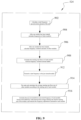
- Fig. 8 shows specific steps of transmitting a frequency load amount to each frequency conversion modular unit in step 518.
- step 802 the processor 304 sums the frequencies of loadable frequency conversion modular units in the frequency conversion modular set 102, obtaining a total frequency ⁇ L of the loadable frequency conversion modular units in the frequency conversion modular set 102. Afterwards, the processor 304 calculates the total frequency up-conversion amount of the frequency conversion modular set 102 by multiplying, based on the energy adjustment coefficient PL calculated in step 408, the total frequency ⁇ L of the loadable frequency conversion modular units with the energy adjustment coefficient PL. After the step 802 is completed, the processor 304 makes operation turn to step 804.
- step 804 the processor 304 divides the total frequency up-conversion amount of the frequency conversion modular set 102 by the number of selected (already operating) frequency conversion modular units to obtain the frequency of each selected (already operating) frequency conversion modular unit after load is performed. Afterwards, the processor 304 makes operation turn to step 806.
- step 808 the processor 304 calculates a running rate Rrun.n of each selected (already operating) frequency conversion modular unit after load is performed. Then, the processor 304 makes operation turn to step 810.
- step 810 the processor 304 sums the running rates of the selected (already operating) frequency conversion modular units, and the sum is divided by the number of selected (already operating) frequency conversion modular units, obtaining an average running rate Rave.run. Then, the processor 304 makes operation turn to step 812.
- step 812 the processor 304 calculates an up-converted/down-converted frequency of each selected (already operating) frequency conversion modular unit according to a difference between the average running rate Rave.run and the running rate of each selected (already operating) frequency conversion modular unit, and transmits a frequency adjusting command to the each selected (already operating) frequency conversion modular unit.
- fmaxn denotes a maximum load frequency of each frequency conversion modular unit
- Rave.run denotes an average running rate
- frun denotes a current operating frequency of the corresponding frequency conversion modular unit.
- Fig. 9 shows specific steps of transmitting a frequency load/unload amount to each frequency conversion modular unit in step 524.
- step 902 the processor 304 sums the frequencies of loadable frequency conversion modular units in the frequency conversion modular set 102, obtaining the total frequency of the loadable frequency conversion modular units in the frequency conversion modular set 102, where the total frequency of the loadable frequency conversion modular units in the frequency conversion modular set 102 is denoted by a symbol ⁇ L. Afterwards, the processor 304 multiplies ⁇ L with PL according to the energy adjustment coefficient PL calculated in step 408 to calculate the total frequency up-conversion amount of the frequency conversion modular set 102. After completing step 902, the processor 304 makes operation turn to step 904.
- step 904 the processor 304 subtracts the frequency of the just started frequency conversion modular unit from the total frequency up-conversion amount of the frequency conversion modular set 102, and divides the result by the number of selected (not including the just started frequency conversion modular unit) already operating frequency conversion modular units, obtaining a frequency of the selected (not including the just started frequency conversion modular unit) already operating frequency conversion modular units after load is performed. Afterwards, the processor 304 makes operation turn to step 906.
- step 906 the processor 304 subtracts the current operating frequency from the frequency of the selected (not including the just started frequency conversion modular units) already operating frequency conversion modular units after load is performed. Afterwards, the processor 304 makes operation turn to step 908.
- step 908 the processor 304 calculates a running rate Rrun.n of each selected (not including the just started frequency conversion modular units) already operating frequency conversion modular unit after load or unload is performed. Afterwards, the processor 304 makes operation turn to step 912.
- step 912 the processor 304 transmits a starting frequency to the just started frequency conversion modular unit. After step 912 is completed, the processor 304 makes operation turn to step 914.
- step 916 the processor 304 calculates the up-converted/down-converted frequency of each selected (not including the just started frequency conversion modular units) already operating frequency conversion modular unit based on the difference between the average running rate Rave.run and the running rate of each selected (not including the just started frequency conversion modular units) already operating frequency conversion modular unit, and transmits a frequency adjustment command to each selected (not including the just started frequency conversion modular units) frequency conversion modular unit.
- fmaxn indicates a maximum load frequency of each frequency conversion modular unit
- Rave.run indicates an average running rate
- frun indicates a current operating frequency of the corresponding frequency conversion modular unit.
- step 916 After the step 916 is completed, the step 524 is completed, and the processor 304 will make operation return to step 402.
- Fig. 10 shows specific steps of transmitting a frequency load/unload amount to each frequency conversion modular unit in step 602.
- step 1002 the processor 304 sums the frequencies of the selected (already operating) frequency conversion modular units in the frequency conversion modular set 102, obtaining the total frequency of the selected (already operating) frequency conversion modular units, and then divides the total frequency of the selected (already operating) frequency conversion modular units by the number of the selected (already operating) frequency conversion modular units to obtain an average frequency of each selected (already operating) frequency conversion modular unit.
- step 1002 the processor 304 makes operation turn to step 1004.
- step 1004 the processor 304 subtracts the current operating frequency from the average frequency of each selected (already operating) frequency conversion modular unit to obtain a frequency variation amount of each selected (already operating) frequency conversion modular unit. Afterwards, the processor 304 makes operation turn to step 1006.
- step 1006 the processor 304 calculates the running rate Rrun.n of each selected (already operating) frequency conversion modular unit after load or unload is performed. Afterwards, the processor 304 makes operation turn to step 1008.
- step 1008 the processor 304 sums the running rates of the selected (already operating) frequency conversion modular units, and divides the result by the number of selected (already operating) frequency conversion modular units to obtain an average running rate Rave.run. Afterwards, the processor 304 will make operation turn to step 1012.
- step 1012 the processor 304 calculates the up-converting/down-converting frequency of each selected (already operating) frequency conversion modular unit based on the difference between the average running rate Rave.run and the running rate of each selected (already operating) frequency conversion modular unit, and transmits a frequency adjustment command to each selected (already operating) frequency conversion modular unit.
- fmaxn indicates the maximum load frequency of each frequency conversion modular unit
- Rave.run indicates an average running rate
- frun indicates the current operating frequency of the corresponding frequency conversion modular unit.
- Fig. 11 shows specific steps of transmitting a frequency load/unload amount to each frequency conversion modular unit in step 714.
- step 1102 the processor 304 sums the frequencies of the loadable frequency conversion modular units in the frequency conversion modular set 102, obtaining a total frequency of the loadable frequency conversion modular units in the frequency conversion modular set 102, wherein the total frequency of the loadable frequency conversion modular units in the frequency conversion modular set 102 is represented by the symbol ⁇ L. Afterwards, the processor 304 multiplies ⁇ L with PL to calculate the total frequency down-conversion amount of the frequency conversion modular set 102 according to the energy adjustment coefficient PL calculated in step 408. After the step 1102 is completed, the processor 304 makes operation turn to step 1104.
- step 1104 the processor 304 subtracts the total frequency down-converting amount from the total frequency down-converting amount of the selected (not including the unloaded frequency conversion modular units) operating frequency conversion modular units, and divides the result by the number of the selected (not including the unloaded frequency conversion modular units) operating frequency conversion modular units, obtaining the frequency of the selected (not including the unloaded frequency conversion modular units) operating frequency conversion modular units after unload is performed. Afterwards, the processor 304 makes operation turn to step 1106.
- step 1106 the processor 304 subtracts the current operating frequency from the frequencies of the selected (not including the unloaded frequency conversion modular units) operating frequency conversion modular units after unload is performed to obtain a frequency variation amount. Afterwards, the processor 304 makes operation turn to step 1108.
- the processor 304 calculates the running rate Rrun.n of each selected (not including the unloaded frequency conversion modular units) operating frequency conversion modular unit after unload is performed. Afterwards, the processor 304 makes operation turn to step 1110.
- step 1110 the processor sums the running rates of the selected (not including the unloaded frequency conversion modular units) already operating frequency conversion modular units, and divides the result by the number of the selected (not including the unloaded frequency conversion modular units) operating frequency conversion modular units to obtain an average running rate Rave.run. Afterwards, the processor 304 makes operation turn to step 1112.
- step 1112 based on a difference between the average running rate Rave.run and the running rate of each selected (not including the unloaded frequency conversion modular units) operating frequency conversion modular unit, the processor 304 calculates the up-converted/down-converted frequency of the rest of (not including the unloaded frequency conversion modular unit) operating frequency conversion modular units, and transmits a frequency adjustment command to each selected (not including the unloaded frequency conversion modular units) operating frequency conversion modular unit.
- fmax.n denotes the maximum load frequency of each frequency conversion modular unit
- Rave.run indicates an average running rate
- frun indicates the current operating frequency of the corresponding frequency conversion modular unit.
- step 1112 After the step 1112 is completed, the step 714 is completed, and the processor 304 makes operation return to step 402.
- Fig. 12 shows specific steps of transmitting a frequency unload amount to each frequency conversion modular unit in step 716.
- step 1204 the processor 304 divides the total frequency down-conversion amount of the frequency conversion modular set 102 by the number of selected (already operating) frequency conversion modular units to obtain the frequency of each selected (already operating) frequency conversion modular unit after unload is performed. Afterwards, the processor 304 makes operation turn to step 1206.
- step 1206 the processor 304 subtracts the current operating frequency from the frequency of each selected (already operating) frequency conversion modular unit after unload is performed, to obtain the frequency variation amount of each selected (already operating) frequency conversion modular unit. Afterwards, the processor 304 makes operation turn to step 1208.
- step 1208 the processor 304 calculates the running rate Rrun.n of each frequency conversion modular unit after unload is performed. Afterwards, the processor 304 makes operation turn to step 1210.
- step 1210 the processor 304 sums the running rates of the selected (already operating) frequency conversion modular units, and divides the sum by the number of selected (already operating) frequency conversion modular units to obtain an average running rate Rave.run. Afterwards, the processor 304 makes operation turn to step 1212.
- step 1212 the processor 304 calculates the up-converted/down-converted frequency of each selected (already operating) frequency conversion modular unit based on the difference between the average running state Rave.run and the running rate of each selected (already operating) frequency conversion modular unit, and transmits a frequency adjustment command to each selected (already operating) frequency conversion modular unit.
- fmax.n denotes a maximum load frequency of each frequency conversion modular unit
- Rave.run denotes an average running rate
- frun denotes a current running frequency of the corresponding frequency conversion modular unit.
- step 1212 After step 1212 is completed, the step 716 is completed; and the processor 304 makes operation return to step 402.
Landscapes
- Engineering & Computer Science (AREA)
- General Engineering & Computer Science (AREA)
- Mechanical Engineering (AREA)
- Chemical & Material Sciences (AREA)
- Combustion & Propulsion (AREA)
- Physics & Mathematics (AREA)
- Signal Processing (AREA)
- Thermal Sciences (AREA)
- Mathematical Physics (AREA)
- Fuzzy Systems (AREA)
- Human Computer Interaction (AREA)
- General Physics & Mathematics (AREA)
- Automation & Control Theory (AREA)
- Air Conditioning Control Device (AREA)
Claims (13)
- Verfahren zum Steuern eines Klimatisierungssystems (100), wobei das Klimatisierungssystem einen modularen Satz (102) umfasst, der eine Vielzahl von modularen Frequenzumwandlungseinheiten (112.1, 112.2, ..., 112.N) aufweist, wobei eine der Vielzahl von modularen Frequenzumwandlungseinheiten (112.1, 112.2, ..., 112.N) als modulare Hauptfrequenzumwandlungseinheit (112.1) eingestellt ist, die eine darauf bereitgestellte Hauptsteuerung (118.1) aufweist, die Hauptsteuerung (118.1) zur Steuerung des Betriebs der Vielzahl der modularen Hauptfrequenzumwandlungseinheiten (112.1, 112.2, ..., 112.N) angeordnet ist, wobei jede der modularen Hauptfrequenzumwandlungseinheiten (112.1, 112.2, ..., 112.N) in Fluidkommunikation mit einer Wasserleitung (110) steht, wobei die Wasserleitung (110) Wasser zur Temperatureinstellung empfängt, wobei die Wasserleitung (110) mit einem Wassertemperatursensor (108) zum Feststellen einer aktuellen Temperatur (Tw) von Wasser, dargestellt durch das Symbol Tw, in der Leitung bereitgestellt wird, und wobei die Hauptsteuerung (118.1) eine Prozessoreinheit (304) umfasst, die so konfiguriert ist, dass sie die folgenden Schritte ausführt:- Einstellen eines optimierten Lastverhältnisbereichs für jede der Vielzahl von modularen Frequenzumwandlungseinheiten (112.1, 112.2, ..., 112.N), wobei innerhalb des optimierten Lastverhältnisbereichs eine Betriebsenergieeffizienz jeder der Vielzahl von modularen Frequenzumwandlungseinheiten (112.1, 112.2, 112.N) größer als oder gleich einem vorbestimmten Energieeffizienzwert ist, wobei der optimierte Lastverhältnisbereich (a, b) innerhalb eines Lastbereichs (s, s') liegt, der gleich oder größer als ein akzeptabler Lastpunkt ist;- Feststellen und Eingeben einer Zieltemperatur (Tw.target) von Wasser, dargestellt durch das Symbol Tw.target;- Feststellen und Eingeben der aktuellen Temperatur (Tw) des Wassers;- Ermitteln einer Menge zur Energieanpassung des Moduls, die nach einem Unterschied zwischen der Zieltemperatur des Wassers und der aktuellen Temperatur des Wassers eingestellt wird;- Eingeben der Menge der Energieanpassung; und- Einstellen verschiedener Betriebe für den modularen Satz (102) nach der Menge an Energie, wobei die verschiedenen Betriebe Folgendes einschließen:(1) einen Lastbetrieb;(2) einen Entlastungsbetrieb; oder(3) einen Haltebetrieb, wobeiim Lastbetrieb Frequenzanpassungsmengen der Vielzahl von modularen Frequenzumwandlungseinheiten (112.1, 112.2, ..., 112.N) basierend auf der Energieanpassungsmenge und den Betriebspositionen innerhalb des optimierten Lastverhältnisbereichs der jeweiligen modularen Frequenzumwandlungseinheiten (112.1, 112.2, ..., 112.N), die am Betrieb der Vielzahl von modularen Frequenzumwandlungseinheiten (112.1, 112.2, ..., 112.N) beteiligt sind, bestimmt werden, oderim Entlastungsbetrieb die Frequenzanpassungsmengen der Vielzahl von modularen Frequenzumwandlungseinheiten (112.1, 112.2, ..., 112.N) basierend auf der Energieanpassungsmenge und den Betriebspositionen innerhalb des optimierten Lastverhältnisbereichs der jeweiligen am Betrieb beteiligten modularen Frequenzumwandlungseinheiten (112.1, 112.2, ..., 112.N) bestimmt werden oder im Haltebetrieb jede der in Betrieb befindlichen modularen Frequenzumwandlungseinheiten nach einem durchschnittlichen Lastverhältnis der Vielzahl von modularen Frequenzumwandlungseinheiten (112.1, 112.2, ..., 112.N) feinabgestimmt wird und der Haltebetrieb bewirkt, dass die Vielzahl von modularen Frequenzumwandlungseinheiten (112.1, 112.2, ..., 112.N) unter einem weiteren Optimierungszustand im optimierten Lastverhältnisbereich arbeitet; undwobei der Lastbetrieb oder der Entlastungsbetrieb bewirkt, dass die mehreren modularen Frequenzumwandlungseinheiten (112.1, 112.2, ..., 112.N) innerhalb des optimierten Lastverhältnisbereichs arbeiten, nachdem der Last- oder Entlastungsbetrieb ausgeführt wurde.
- Verfahren nach Anspruch 1,wobei der optimierte Lastverhältnisbereich einen minimalen Wert a des optimierten Lastverhältnisbereichs und einen maximalen Wert b des optimierten Lastverhältnisbereichs aufweist, und wobei der Lastbetrieb die folgenden Schritte umfasst:- basierend auf der Menge der Energieanpassung, Berechnen eines durchschnittlichen Lastverhältnisses jeder in Betrieb befindlichen modularen Frequenzumwandlungseinheit, nachdem die Last ausgeführt wurde;- Vergleichen des durchschnittlichen Lastverhältnisses nach dem Ausführen der Last mit b;wenn das durchschnittliche Lastverhältnis nach der Last ausgeführt wird ≥ b,(i) Suchen, ob eine modulare Frequenzumwandlungseinheit (112.1, 112.2, ..., 112.N) vorhanden ist, die nicht am Betrieb teilnimmt,(ii) wenn die modulare Frequenzumwandlungseinheit nicht am Betrieb teilnimmt, Starten der nicht am Betrieb teilnehmenden modularen Frequenzumwandlungseinheit (112.1, 112.2, ..., 112.N),(iii) Berechnen eines durchschnittlichen Lastverhältnisses der gerade in Betrieb genommenen modularen Frequenzumwandlungseinheit und der in Betrieb befindlichen modularen Frequenzumwandlungseinheiten,(iv) Senden eines Frequenzanpassungsbefehls an die gerade in Betrieb genommene modulare Frequenzumwandlungseinheit und die in Betrieb befindlichen modularen Frequenzumwandlungseinheiten;wenn das durchschnittliche Lastverhältnis nach dem Ausführen der Last < b oder das durchschnittliche Lastverhältnis nach dem Ausführen der Last ≥b ist und die modulare Frequenzumwandlungseinheit (112.1, 112.2, ..., 112.N) nicht am Betrieb teilnimmt, nicht gefunden wird,(i) Berechnen eines durchschnittlichen Lastverhältnisses der am Betrieb beteiligten modularen Frequenzumwandlungseinheiten (112.1, 112.2, ..., 112.N),(ii) Senden eines Frequenzanpassungsbefehls an die betriebsmäßigen modularen Frequenzumwandlungseinheiten; und/oderwobei der optimierte Lastverhältnisbereich einen minimalen Wert a des optimierten Lastverhältnisbereichs und einen maximalen Wert b des optimierten Lastverhältnisbereichs aufweist, und wobei der Lastbetrieb die folgenden Schritte umfasst:- nach der Menge der Energieanpassung, Berechnen eines durchschnittlichen Lastverhältnisses jeder in Betrieb befindlichen modularen Frequenzumwandlungseinheit, nachdem die Entladung ausgeführt wurde;- Vergleichen des durchschnittlichen Lastverhältnisses nach dem Ausführen der Entladung mit a;wenn das durchschnittliche Lastverhältnis nach dem Entladen ausgeführt wird ≤ a,(i) Suchen, ob eine abschaltbare modulare Frequenzumwandlungseinheit vorhanden ist,(ii) wenn die abschaltbare modulare Frequenzumwandlungseinheit gefunden wird, Entladen der gefundenen abschaltbaren modularen Frequenzumwandlungseinheit und Abschalten derselben,(iii) Berechnen eines durchschnittlichen Lastverhältnisses der in Betrieb befindlichen modularen Frequenzumwandlungseinheiten mit Ausnahme der abgeschalteten modularen Frequenzumwandlungseinheit,(iv) Senden eines Frequenzanpassungsbefehls an die betriebsmäßigen modularen Frequenzumwandlungseinheiten, die nicht die abgeschaltete modulare Frequenzumwandlungseinheit sind;wenn das durchschnittliche Lastverhältnis nach dem Entladen >a ausgeführt wird oder wenn das durchschnittliche Lastverhältnis nach dem Entladen ≤a ausgeführt wird und die abschaltbare modulare Frequenzumwandlungseinheit nicht gefunden wird,(i) Berechnen eines durchschnittlichen Lastverhältnisses der in Betrieb befindlichen modularen Frequenzumwandlungseinheiten,(ii) Senden eines Frequenzanpassungsbefehls an die betriebsmäßigen modularen Frequenzumwandlungseinheiten.
- Verfahren nach einem der Ansprüche 1 bis 2,wobei der Entladeschritt das Entladen einer modularen Frequenzumwandlungseinheit mit der längsten betriebsmäßigen Zeit umfasst; und/oderwobei der Schritt des Sendens eines Frequenzanpassungsbefehls an die modulare Betriebsfrequenzumwandlungseinheit den folgenden Schritt umfasst: wenn die modularen Betriebsfrequenzumwandlungseinheiten bereits auf einer niedrigsten Frequenz sind, die modularen Betriebsfrequenzumwandlungseinheiten nicht anzupassen, wodurch die modularen Betriebsfrequenzumwandlungseinheiten veranlasst werden, weiterhin auf der niedrigsten Frequenz zu arbeiten.
- Verfahren nach Anspruch 2,
wobei der Schritt des Sendens eines Frequenzanpassungsbefehls an die gerade in Betrieb genommene modulare Frequenzumwandlungseinheit und die in Betrieb befindlichen modularen Frequenzumwandlungseinheiten folgende Schritte umfasst:- Berechnen einer Gesamtfrequenz von ladbaren modularen Frequenzumwandlungseinheiten des modularen Frequenzumwandlungssatzes (102);- Bestimmen eines Energieanpassungskoeffizienten des modularen Frequenzumwandlungssatzes (102) nach dem Lastverhältnis und eines Korrekturkoeffizienten für die Variation der Wassertemperatur;- Berechnen einer Gesamtmenge für die Frequenzumwandlung nach der Gesamtfrequenz der modularen Frequenzumwandlungseinheit und dem Energieanpassungskoeffizienten;- Berechnen der Frequenzen der gerade in Betrieb genommenen modularen Frequenzumwandlungseinheit und der modularen Frequenzumwandlungseinheiten nach dem Ausführen des Lastbetriebs, nach der Gesamtmenge der Frequenzumwandlung;- Berechnen der Mengen an Variationen der Frequenzen nach den Unterschieden zwischen den Frequenzen der modularen Frequenzumwandlungseinheit, die gerade in Betrieb genommen wurde, und den modularen Frequenzumwandlungseinheiten, die in Betrieb sind, nachdem der Lastbetrieb ausgeführt wurde, und einer aktuellen Betriebsfrequenz;- Berechnen der Raten der in Betrieb befindlichen modularen Frequenzumwandlungseinheit nach dem Ausführen der Last;- Berechnen einer durchschnittlichen Laufrate der in Betrieb befindlichen modularen Frequenzumwandlungseinheiten, die nicht die gerade gestartete modulare Frequenzumwandlungseinheit sind, nach den Laufraten der in Betrieb befindlichen modularen Frequenzumwandlungseinheiten, nachdem die Last ausgeführt wurde; und- Berechnen einer aufwärts/abwärts gewandelten Frequenz nach einem Durchschnittswert zwischen der durchschnittlichen laufenden Rate und der laufenden Rate jeder der modularen Betriebsfrequenzumwandlungseinheiten, die nicht die gerade gestartete modulare Frequenzumwandlungseinheit ist, und Senden des Frequenzeinstellbefehls an jede der modularen Betriebsfrequenzumwandlungseinheiten, die nicht die gerade gestartete modulare Frequenzumwandlungseinheit ist. - Verfahren nach Anspruch 2,
wobei der Schritt des Sendens eines Frequenzanpassungsbefehls an die betriebsmäßigen modularen Frequenzumwandlungseinheiten die folgenden Schritte umfasst:- Berechnen einer Gesamtfrequenz der ladbaren modularen Frequenzumwandlungseinheiten im modularen Frequenzumwandlungssatz (102);- Bestimmen eines Energieanpassungskoeffizienten des modularen Satzes des Frequenzumrichters nach dem Lastverhältnis und dem Korrekturkoeffizienten der Wassertemperaturänderung;- Berechnen einer Gesamtmenge für die Frequenzumwandlung nach der Gesamtfrequenz der modularen Frequenzumwandlungseinheiten und dem Energieanpassungskoeffizienten;- nach der gesamten Menge der Frequenzumwandlung, Berechnen der Frequenz der modularen Frequenzumwandlungseinheiten im Betrieb nach dem Ausführen der Last;- Berechnen der Mengen an Variationen der Frequenzen nach den Unterschieden zwischen den Frequenzen der modularen Frequenzumwandlungseinheiten im Betrieb, nachdem der Lastbetrieb ausgeführt wurde, und der aktuellen Betriebsfrequenz;- Berechnen der Raten der in Betrieb befindlichen modularen Frequenzumwandlungseinheiten nach dem Ausführen der Last;- nach den Laufraten der betriebsmäßigen modularen Frequenzumwandlungseinheiten nach dem Ausführen der Last, Berechnen einer durchschnittlichen Laufrate der betriebsmäßigen modularen Frequenzumwandlungseinheiten nach dem Ausführen der Last; und- Berechnen einer aufwärts/abwärts gewandelten Frequenz nach einem Durchschnittswert zwischen der durchschnittlichen Laufrate und der Laufrate jeder der modularen Betriebsfrequenzumwandlungseinheiten, nachdem die Mittelung ausgeführt wurde, und Senden des Frequenzeinstellbefehls an jede der modularen Betriebsfrequenzumwandlungseinheiten. - Verfahren nach Anspruch 2,
wobei der Schritt des Sendens eines Einstellbefehls an die betriebsmäßigen modularen Frequenzumwandlungseinheiten, die nicht die abgeschaltete modulare Frequenzumwandlungseinheit sind, die folgenden Schritte umfasst:- Berechnen einer Gesamtfrequenz der ladbaren modularen Frequenzumwandlungseinheiten im modularen Frequenzumwandlungssatz (102);- Bestimmen eines Energieanpassungskoeffizienten des modularen Satzes des Frequenzumrichters nach dem Entlastungsverhältnis und dem Korrekturkoeffizienten der Wassertemperaturänderung;- Berechnen einer Gesamtmenge der Frequenzabwärtsumwandlung nach der Gesamtfrequenz der ladbaren modularen Frequenzumwandlungseinheiten und dem Energieanpassungskoeffizienten;- nach der gesamten Menge der Frequenzabwärtsumwandlung, Berechnen der Frequenz der in Betrieb befindlichen modularen Frequenzumwandlungseinheiten, die nicht die unbelastete modulare Frequenzumwandlungseinheit sind, nachdem die Entlastung ausgeführt wurde;- Berechnen der Mengen an Variationen der Frequenzen nach den Unterschieden zwischen den Frequenzen der modularen Frequenzumwandlungseinheiten im Betrieb, nachdem die Entladung ausgeführt wurde, und der aktuellen Betriebsfrequenz;- Berechnen der Laufraten der betriebsmäßigen modularen Frequenzumwandlungseinheiten, nachdem die Entladung ausgeführt wurde;- Berechnen einer durchschnittlichen Laufrate der modularen Frequenzumwandlungseinheiten im Betrieb, die von den unbelasteten Frequenzen unterschiedlich sind, nach den Laufraten der modularen Frequenzumwandlungseinheiten im Betrieb, nachdem die Entlastung ausgeführt wurde; und- Berechnen einer aufwärts/abwärts gewandelten Frequenz nach einem Durchschnittswert zwischen der durchschnittlichen Laufrate und der Laufrate jeder der modularen Betriebsfrequenzumwandlungseinheiten mit Ausnahme der entladenen modularen Frequenzumwandlungseinheit, nachdem die Entladung ausgeführt wurde, und Senden des Frequenzanpassungsbefehls an jede der modularen Betriebsfrequenzumwandlungseinheiten mit Ausnahme der gerade gestarteten modularen Frequenzumwandlungseinheit. - Verfahren nach Anspruch 2,
wobei der Schritt des Sendens eines Frequenzanpassungsbefehls an die betriebsmäßigen modularen Frequenzumwandlungseinheiten die folgenden Schritte umfasst:- Berechnen einer Gesamtfrequenz der ladbaren modularen Frequenzumwandlungseinheiten im modularen Frequenzumwandlungssatz (102);- Bestimmen eines Energieanpassungskoeffizienten des modularen Satzes des Frequenzumrichters nach dem Lastverhältnis und dem Korrekturkoeffizienten der Wassertemperaturänderung;- Bestimmen einer Gesamtmenge der Frequenzabwärtsumwandlung nach der Gesamtfrequenz der ladbaren modularen Frequenzumwandlungseinheiten und dem Energieanpassungskoeffizienten;- nach der gesamten Menge der Frequenzabwärtsumwandlung, Berechnen der Frequenz der in Betrieb befindlichen modularen Frequenzumwandlungseinheiten, nachdem die Entladung ausgeführt wurde;- Berechnen der Mengen an Variationen der Frequenzen nach den Unterschieden zwischen den Frequenzen der modularen Frequenzumwandlungseinheiten im Betrieb, nachdem die Entladung ausgeführt wurde, und der aktuellen Betriebsfrequenz;- Berechnen der Laufraten der betriebsmäßigen modularen Frequenzumwandlungseinheiten, nachdem die Entladung ausgeführt wurde;- Berechnen einer durchschnittlichen Laufrate der modularen Betriebsfrequenzumwandlungseinheiten nach dem Ausführen der Entladung nach den Laufraten der modularen Betriebsfrequenzumwandlungseinheiten nach dem Ausführen der Entladung; und- Berechnen einer aufwärts/abwärts gewandelten Frequenz nach einem Unterschiedswert zwischen der durchschnittlichen Laufrate und der Laufrate jeder der modularen Betriebsfrequenzumwandlungseinheiten, nachdem die Entladung ausgeführt wurde, und Senden des Frequenzeinstellbefehls an jede der modularen Betriebsfrequenzumwandlungseinheiten. - Verfahren nach einem der Ansprüche 1 bis 7,
wobei der Schritt der Feinabstimmung jeder der modularen Frequenzumwandlungseinheiten im Betrieb nach einem durchschnittlichen Lastverhältnis der Vielzahl von modularen Frequenzumwandlungseinheiten (112.1, 112.2, ..., 112.N) die folgenden Schritte umfasst:- Berechnen einer Gesamtfrequenz der modularen Frequenzumwandlungseinheiten im Betrieb;- Berechnen einer durchschnittlichen Frequenz der modularen Frequenzumwandlungseinheiten im Betrieb nach der Gesamtfrequenz der modularen Frequenzumwandlungseinheiten im Betrieb;- Berechnen einer Menge von Frequenzvariationen nach einem Unterschied zwischen der durchschnittlichen Frequenz der modularen Frequenzumwandlungseinheiten im Betrieb und der aktuellen Betriebsfrequenz;- Berechnen der Laufraten der in Betrieb befindlichen modularen Frequenzumwandlungseinheiten, nachdem der Last-/Entlastungsvorgang ausgeführt wurde;- Berechnen einer durchschnittlichen Laufrate der modularen Frequenzumwandlungseinheiten nach dem Ausführen der Last/Entlastung nach den Laufraten der modularen Frequenzumwandlungseinheiten der Last/Entlastung; und- Berechnen einer aufwärts/abwärts gewandelten Frequenz nach einem Durchschnittswert zwischen der durchschnittlichen Laufrate und der Laufrate jeder der modularen Betriebsfrequenzumwandlungseinheiten, und Senden des Frequenzeinstellbefehls an jede der modularen Betriebsfrequenzumwandlungseinheiten. - Verfahren nach einem der Ansprüche 1 bis 8,wobei die unterschiedlichen Betriebe zu dem modularen Satz (102) die folgenden Schritte umfassen:(i) Tw-Tw.target>D in einem Kühlarbeitszustand, oder wenn Tw.target-Tw>D in einem Heizarbeitszustand, Einstellen als Lastbetrieb;(ii) wenn -D≤Tw.target≤D im Kühlarbeitszustand, oder wenn - D≤Tw.target-Tw≤D im Heizarbeitszustand, Einstellen als Haltebetrieb;(iii) wenn Tw-Tw.target<-D im Kühlarbeitszustand, oder wenn Tw.target-Tw<-D im Heizarbeitszustand, Einstellen als Entlastungsbetrieb;wobei der Wert D nach einem Genauigkeitsgrad der Wassertemperaturregelung eingestellt werden kann; undwobei das Lastverhältnis des modularen Satzes (102) in einem Lastbereich auf ein großes Lastverhältnis eingestellt ist, das Last-/Entlastungsverhältnis des modularen Satzes (102) in einem Feinabstimmungsbereich auf ein kleines Lastverhältnis oder ein kleines Entlastungsverhältnis eingestellt ist und das Entlastungsverhältnis des modularen Satzes in dem Entlastungsbereich auf ein großes Entlastungsverhältnis eingestellt ist.
- Verfahren nach einem der Ansprüche 1 bis 9,wobei das Verfahren ferner die folgenden Schritte umfasst:- Bestimmen eines Minimalwertes (a) des optimierten Lastverhältnisbereiches und eines maximalen Wertes (b) des optimierten Lastverhältnisbereiches;wobei
 wobei
wobei wobei n eine Gesamtzahl von Modulen bezeichnet, deren Betrieb im System nicht begrenzt ist, t ein Lastverhältnis bezeichnet, wenn das Modul die höchste betriebsmäßige Energieeffizienz (cop MAX) aufweist, s ein Startlastverhältnis bezeichnet, s' ein entsprechendes Lastverhältnis bezeichnet, das den höchsten betriebsmäßigen Energieeffizienzwert (cop MAX) als Startlastverhältnis aufweist, wenn das Lastverhältnis höher als t ist, und x1 und x2 Abweichungen sind, die eingestellt sind, um ein häufiges Starten/Stoppen des Moduls zu verhindern.
 - Verfahren nach einem der Ansprüche 1 bis 10,
wobei der modulare Satz (102) über die Wasserleitung (10) in Fluidkommunikation mit einer Vielzahl von Inneneinheiten (124.1, 124.2, ..., 124.N) und einer Vielzahl von Fußbodenheizungseinheiten (132.1, 132.2, ..., 132.N) steht. - Klimatisierungssystem, das einen modularen Satz (102) umfasst, der eine Vielzahl von modularen Frequenzumwandlungseinheiten (112.1, 112.2, ..., 112.N) einschließt, dadurch gekennzeichnet, dass das Klimatisierungssystem Folgendes umfasst:- eine Hauptsteuerung (118.1), wobeieine aus der Vielzahl der modularen Frequenzumwandlungseinheiten (112.1, 112.2, ..., 112.N) mittels der Hauptsteuerung (118.1) als modulare Hauptfrequenzumwandlungseinheit (112.1) eingestellt wird, während die übrigen aus der Vielzahl der modularen Frequenzumwandlungseinheiten (112.1, 112.2, ..., 112.N) mittels der Hauptsteuerung (118.1) als modulare Nebenfrequenzumwandlungseinheiten (1, 2, ..., N-1) eingestellt werden;die Hauptsteuerung (118.1) mit der modularen Hauptfrequenzumwandlungseinheit (112.1) verbunden ist und auch mit den modularen Nebenfrequenzumwandlungseinheiten (1, 2, ..., N-1) verbunden ist;jede der modularen Frequenzumwandlungseinheiten (112.1, 112.2, ..., 112.N) in Fluidkommunikation mit einer Wasserleitung (110) steht, wobei die Wasserleitung (110) Wasser zur Temperatureinstellung empfängt und mit einem Wassertemperatursensor (108) zum Feststellen einer aktuellen Temperatur (Tw) des Wassers, dargestellt durch das Symbol Tw, bereitgestellt wird; und die Hauptsteuerung (118.1) so konfiguriert ist, dass sie (1) einen Lastbetrieb, (2) einen Entlastungsbetrieb oder (3) einen Haltebetrieb für die Vielzahl von modularen Frequenzumwandlungseinheiten (112.1, 112.2, ..., 112.N) nach einer Energieeinstellmenge ausführt, die nach dem Verfahren nach einem der Ansprüche 1 bis 11 eingegeben wird.
- Klimatisierungssystem nach Anspruch 12,
wobei die Hauptsteuerung (118.1) auf der modularen Hauptfrequenzumwandlungseinheit (112.1) angeordnet ist; und/oder wobei der modulare Satz (102) in Fluidkommunikation mit einer Vielzahl von Inneneinheiten (124.1, 124.2, ..., 124.N) und einer Vielzahl von Fußbodenheizungseinheiten (132.1, 132.2, ..., 132.N) steht.
Applications Claiming Priority (1)
| Application Number | Priority Date | Filing Date | Title |
|---|---|---|---|
| CN201710151811.5A CN108626923B (zh) | 2017-03-15 | 2017-03-15 | 一种空调系统的控制结构以及控制方法 |
Publications (2)
| Publication Number | Publication Date |
|---|---|
| EP3376128A1 EP3376128A1 (de) | 2018-09-19 |
| EP3376128B1 true EP3376128B1 (de) | 2023-10-18 |
Family
ID=61598989
Family Applications (1)
| Application Number | Title | Priority Date | Filing Date |
|---|---|---|---|
| EP18160581.7A Active EP3376128B1 (de) | 2017-03-15 | 2018-03-07 | Steuerungsstruktur einer klimaanlage und steuerungsverfahren dafür |
Country Status (5)
| Country | Link |
|---|---|
| US (1) | US10578331B2 (de) |
| EP (1) | EP3376128B1 (de) |
| CN (1) | CN108626923B (de) |
| HU (1) | HUE066336T2 (de) |
| PL (1) | PL3376128T3 (de) |
Families Citing this family (24)
| Publication number | Priority date | Publication date | Assignee | Title |
|---|---|---|---|---|
| CN108488914A (zh) * | 2018-04-13 | 2018-09-04 | 珠海格力电器股份有限公司 | 空调机组、空调机组的操作方法和装置 |
| CN109816227A (zh) * | 2019-01-15 | 2019-05-28 | 新奥数能科技有限公司 | 能源设备的管理方法及装置、存储介质、电子装置 |
| CN111981642B (zh) * | 2019-05-21 | 2022-01-25 | 青岛海尔空调电子有限公司 | 热泵空调系统模块机组的能量调节控制方法 |
| CN111023408B (zh) * | 2019-11-25 | 2021-06-15 | 顿汉布什(中国)工业有限公司 | 一种空调机组设计计算及其配套软件编写方法 |
| CN110864417A (zh) * | 2019-11-27 | 2020-03-06 | 无锡同方人工环境有限公司 | 一种空调系统的节能控制方法、装置及系统 |
| CN112880115B (zh) * | 2019-11-29 | 2022-05-20 | 青岛海尔空调电子有限公司 | 多机组空调系统的控制方法 |
| CN111076387B (zh) * | 2019-12-05 | 2020-12-22 | 珠海格力电器股份有限公司 | 一种变频式离心机组及其控制方法、存储介质和空调 |
| CN111102691B (zh) * | 2019-12-17 | 2021-07-30 | 青岛海信日立空调系统有限公司 | 模块组合空调系统 |
| CN113324318B (zh) * | 2020-02-28 | 2022-10-25 | 青岛海尔中央空调有限公司 | 风冷模块机组的控制方法 |
| CN111442480A (zh) * | 2020-04-08 | 2020-07-24 | 广东美的暖通设备有限公司 | 空调设备的运行控制方法和系统、空调设备和存储介质 |
| CN111981624A (zh) * | 2020-08-31 | 2020-11-24 | 宁波奥克斯电气股份有限公司 | 地暖空调及其控制方法 |
| CN112432327A (zh) * | 2020-11-20 | 2021-03-02 | 珠海格力电器股份有限公司 | 空调系统冷水机组运行控制方法、装置及空调系统 |
| JP7624614B2 (ja) * | 2020-12-04 | 2025-01-31 | パナソニックIpマネジメント株式会社 | 空調制御システム、空調システム、空調制御方法、及びプログラム |
| CN112648714B (zh) * | 2020-12-09 | 2022-04-05 | 广东西屋康达空调有限公司 | 一种风冷模块机组的恒温控制方法及系统 |
| CN112665145B (zh) * | 2020-12-16 | 2022-03-11 | 珠海格力电器股份有限公司 | 双级系统协同控制方法、装置、控制器和空气处理机组 |
| CN112728724B (zh) * | 2021-02-01 | 2023-02-28 | 南京天加环境科技有限公司 | 一种中央空调系统的能量调节方式 |
| CN113203231B (zh) * | 2021-05-07 | 2023-01-03 | 广州市华德工业有限公司 | 机组的能量调节方法、装置和机组 |
| CN113266923B (zh) * | 2021-05-26 | 2022-10-14 | 广东申菱商用空调设备有限公司 | 一种压缩机的控制方法及控制装置 |
| CN113719965B (zh) * | 2021-08-16 | 2022-09-27 | 宁波奥克斯电气股份有限公司 | 压缩机的频率控制方法、装置及变频空调器 |
| CN115682303B (zh) * | 2022-11-07 | 2024-07-19 | 珠海格力电器股份有限公司 | 多模块空调系统及其控制方法、存储介质 |
| CN116123677A (zh) * | 2022-12-08 | 2023-05-16 | 蘑菇物联技术(深圳)有限公司 | 控制空调系统的主机的方法、设备和存储介质 |
| CN116242007A (zh) * | 2023-01-20 | 2023-06-09 | 约克广州空调冷冻设备有限公司 | 控制空调系统中的压缩机的方法和装置 |
| CN116624967B (zh) * | 2023-06-19 | 2025-12-09 | 珠海亚丁科技有限公司 | 压缩机频率控制方法、装置、设备及存储介质 |
| CN117053446A (zh) * | 2023-08-30 | 2023-11-14 | 珠海格力电器股份有限公司 | 控制方法、控制装置、冷水机组和计算机可读存储介质 |
Family Cites Families (24)
| Publication number | Priority date | Publication date | Assignee | Title |
|---|---|---|---|---|
| JPH07234038A (ja) * | 1994-02-18 | 1995-09-05 | Sanyo Electric Co Ltd | 多室型冷暖房装置及びその運転方法 |
| US6148019A (en) * | 1999-05-10 | 2000-11-14 | Inductotherm Corp. | Modular high power induction heating and melting system |
| AU2002305270A1 (en) * | 2001-04-30 | 2002-11-11 | Emerson Retail Services Inc. | Building system performance analysis |
| JP4435533B2 (ja) * | 2003-10-09 | 2010-03-17 | 高砂熱学工業株式会社 | 熱源システム及び制御装置 |
| JP4619303B2 (ja) * | 2006-02-27 | 2011-01-26 | 三菱電機株式会社 | 空気調和装置 |
| US20090277196A1 (en) * | 2008-05-01 | 2009-11-12 | Gambiana Dennis S | Apparatus and method for modulating cooling |
| US8651391B2 (en) * | 2008-06-17 | 2014-02-18 | Ronald Harrison Patch | Method and apparatus for control of cooling system air quality and energy consumption |
| JP5404132B2 (ja) * | 2009-03-30 | 2014-01-29 | 三菱重工業株式会社 | 熱源システムおよびその制御方法 |
| US8515584B2 (en) * | 2009-08-20 | 2013-08-20 | Transformative Wave Technologies Llc | Energy reducing retrofit method for a constant volume HVAC system |
| JP5404333B2 (ja) * | 2009-11-13 | 2014-01-29 | 三菱重工業株式会社 | 熱源システム |
| US8005640B2 (en) * | 2009-12-18 | 2011-08-23 | Indie Energy Systems Co., LLC | Thermal response geothermal testing unit |
| US20130098086A1 (en) * | 2011-04-19 | 2013-04-25 | Liebert Corporation | Vapor compression cooling system with improved energy efficiency through economization |
| CN102353122B (zh) * | 2011-09-26 | 2013-06-19 | Tcl空调器(中山)有限公司 | 一种模块式多联机控制方法及系统 |
| KR101303162B1 (ko) * | 2011-11-16 | 2013-09-09 | 엘지전자 주식회사 | 공기 조화기와, 이를 포함한 공기 조화 시스템, 및 조명 시스템 |
| US9410752B2 (en) * | 2012-08-17 | 2016-08-09 | Albert Reid Wallace | Hydronic building systems control |
| JP5447627B1 (ja) * | 2012-09-26 | 2014-03-19 | ダイキン工業株式会社 | 熱源システム制御装置 |
| KR101985810B1 (ko) * | 2012-10-25 | 2019-09-03 | 삼성전자주식회사 | 히트펌프 및 그 제어방법 |
| JP6301784B2 (ja) * | 2014-08-28 | 2018-03-28 | 荏原冷熱システム株式会社 | 熱源システムに使用される制御装置、および該制御装置を備えた熱源システム |
| CN104251529B (zh) * | 2014-10-16 | 2016-09-21 | 中国扬子集团滁州扬子空调器有限公司 | 一种复合式制冷多联空调系统 |
| CN104566787B (zh) * | 2014-12-17 | 2017-09-15 | 中国南方航空工业(集团)有限公司 | 冷水机组的节能控制方法及控制系统 |
| JP6075659B2 (ja) * | 2015-03-31 | 2017-02-08 | 三菱電機株式会社 | 空調管理装置、空調管理方法、及び、プログラム |
| CN105042938B (zh) * | 2015-08-06 | 2018-01-02 | 广东美的暖通设备有限公司 | 风冷热泵冷热水机系统及其加卸载控制方法 |
| US10401046B2 (en) * | 2016-10-05 | 2019-09-03 | Johnson Controls Technology Company | Indoor and outdoor units for an HVAC system |
| US11042924B2 (en) * | 2017-03-10 | 2021-06-22 | Johnson Controls Technology Company | Building controller for optimizing equipment upgrades with design of experiments |
-
2017
- 2017-03-15 CN CN201710151811.5A patent/CN108626923B/zh active Active
-
2018
- 2018-03-07 HU HUE18160581A patent/HUE066336T2/hu unknown
- 2018-03-07 EP EP18160581.7A patent/EP3376128B1/de active Active
- 2018-03-07 PL PL18160581.7T patent/PL3376128T3/pl unknown
- 2018-03-14 US US15/921,347 patent/US10578331B2/en active Active
Also Published As
| Publication number | Publication date |
|---|---|
| US10578331B2 (en) | 2020-03-03 |
| CN108626923B (zh) | 2021-10-22 |
| EP3376128A1 (de) | 2018-09-19 |
| HUE066336T2 (hu) | 2024-08-28 |
| PL3376128T3 (pl) | 2024-07-08 |
| US20180266721A1 (en) | 2018-09-20 |
| CN108626923A (zh) | 2018-10-09 |
Similar Documents
| Publication | Publication Date | Title |
|---|---|---|
| EP3376128B1 (de) | Steuerungsstruktur einer klimaanlage und steuerungsverfahren dafür | |
| US11585561B2 (en) | Control method and device for air conditioning system and air conditioning system | |
| CN111692736B (zh) | 电子膨胀阀的控制方法及空调系统 | |
| CN108700359B (zh) | 用于多压缩机的压缩机容量调节系统 | |
| CN103486689B (zh) | 空调器的控制方法及装置 | |
| JP5511578B2 (ja) | 冷凍機制御装置 | |
| CN107300243B (zh) | 空调系统、风档调节方法及计算机可读存储介质 | |
| CN114935226B (zh) | 空调器的控制方法、控制器、空调器和存储介质 | |
| US9989288B2 (en) | System for managing lubricant levels in tandem compressor assemblies of an HVAC system | |
| EP3467390B1 (de) | Multisplit-system und verfahren zur steuerung der erwärmung eines drosselungselements dafür | |
| CN113339946B (zh) | 空调器运行控制方法、装置、空调器和计算机存储介质 | |
| CN115930410B (zh) | 频率控制曲线的调整方法、装置、空调及存储介质 | |
| EP3411642B1 (de) | Verfahren zur steuerung eines gebläses eines dampfkompressionssystems in übereinstimmung mit einem variablen temperatursollwert | |
| US20160153686A1 (en) | Air-conditioning apparatus | |
| WO2024120251A1 (zh) | 充电系统的冷却系统及其控制方法 | |
| AU2023301836B2 (en) | Method and apparatus for controlling multi-module water chilling unit | |
| CN107339834B (zh) | 自然冷却机组的控制方法和装置 | |
| CN115325665B (zh) | 中央空调的节能优化控制方法、设备及系统 | |
| CN114370727A (zh) | 压缩机控制方法、控制装置及空调器 | |
| JP6301784B2 (ja) | 熱源システムに使用される制御装置、および該制御装置を備えた熱源システム | |
| CN112728724A (zh) | 一种中央空调系统的能量调节方式 | |
| CN113091237B (zh) | 一种空调器控制方法、装置及空调器 | |
| JP6586182B2 (ja) | 熱源システムに使用される制御装置、および該制御装置を備えた熱源システム | |
| CN117345681B (zh) | 变频风机的控制方法及变频空调、存储介质、电子装置 | |
| CN116734323B (zh) | 一种空调器及空调器的频率控制方法 |
Legal Events
| Date | Code | Title | Description |
|---|---|---|---|
| PUAI | Public reference made under article 153(3) epc to a published international application that has entered the european phase |
Free format text: ORIGINAL CODE: 0009012 |
|
| STAA | Information on the status of an ep patent application or granted ep patent |
Free format text: STATUS: REQUEST FOR EXAMINATION WAS MADE |
|
| 17P | Request for examination filed |
Effective date: 20180307 |
|
| AK | Designated contracting states |
Kind code of ref document: A1 Designated state(s): AL AT BE BG CH CY CZ DE DK EE ES FI FR GB GR HR HU IE IS IT LI LT LU LV MC MK MT NL NO PL PT RO RS SE SI SK SM TR |
|
| AX | Request for extension of the european patent |
Extension state: BA ME |
|
| STAA | Information on the status of an ep patent application or granted ep patent |
Free format text: STATUS: EXAMINATION IS IN PROGRESS |
|
| 17Q | First examination report despatched |
Effective date: 20211109 |
|
| GRAP | Despatch of communication of intention to grant a patent |
Free format text: ORIGINAL CODE: EPIDOSNIGR1 |
|
| STAA | Information on the status of an ep patent application or granted ep patent |
Free format text: STATUS: GRANT OF PATENT IS INTENDED |
|
| INTG | Intention to grant announced |
Effective date: 20230504 |
|
| GRAS | Grant fee paid |
Free format text: ORIGINAL CODE: EPIDOSNIGR3 |
|
| GRAA | (expected) grant |
Free format text: ORIGINAL CODE: 0009210 |
|
| STAA | Information on the status of an ep patent application or granted ep patent |
Free format text: STATUS: THE PATENT HAS BEEN GRANTED |
|
| AK | Designated contracting states |
Kind code of ref document: B1 Designated state(s): AL AT BE BG CH CY CZ DE DK EE ES FI FR GB GR HR HU IE IS IT LI LT LU LV MC MK MT NL NO PL PT RO RS SE SI SK SM TR |
|
| REG | Reference to a national code |
Ref country code: GB Ref legal event code: FG4D |
|
| REG | Reference to a national code |
Ref country code: CH Ref legal event code: EP |
|
| REG | Reference to a national code |
Ref country code: DE Ref legal event code: R096 Ref document number: 602018059462 Country of ref document: DE |
|
| REG | Reference to a national code |
Ref country code: IE Ref legal event code: FG4D |
|
| REG | Reference to a national code |
Ref country code: LT Ref legal event code: MG9D |
|
| REG | Reference to a national code |
Ref country code: NL Ref legal event code: MP Effective date: 20231018 |
|
| REG | Reference to a national code |
Ref country code: AT Ref legal event code: MK05 Ref document number: 1622779 Country of ref document: AT Kind code of ref document: T Effective date: 20231018 |
|
| PG25 | Lapsed in a contracting state [announced via postgrant information from national office to epo] |
Ref country code: NL Free format text: LAPSE BECAUSE OF FAILURE TO SUBMIT A TRANSLATION OF THE DESCRIPTION OR TO PAY THE FEE WITHIN THE PRESCRIBED TIME-LIMIT Effective date: 20231018 |
|
| PG25 | Lapsed in a contracting state [announced via postgrant information from national office to epo] |
Ref country code: GR Free format text: LAPSE BECAUSE OF FAILURE TO SUBMIT A TRANSLATION OF THE DESCRIPTION OR TO PAY THE FEE WITHIN THE PRESCRIBED TIME-LIMIT Effective date: 20240119 |
|
| PG25 | Lapsed in a contracting state [announced via postgrant information from national office to epo] |
Ref country code: IS Free format text: LAPSE BECAUSE OF FAILURE TO SUBMIT A TRANSLATION OF THE DESCRIPTION OR TO PAY THE FEE WITHIN THE PRESCRIBED TIME-LIMIT Effective date: 20240218 |
|
| PG25 | Lapsed in a contracting state [announced via postgrant information from national office to epo] |
Ref country code: LT Free format text: LAPSE BECAUSE OF FAILURE TO SUBMIT A TRANSLATION OF THE DESCRIPTION OR TO PAY THE FEE WITHIN THE PRESCRIBED TIME-LIMIT Effective date: 20231018 |
|
| PG25 | Lapsed in a contracting state [announced via postgrant information from national office to epo] |
Ref country code: AT Free format text: LAPSE BECAUSE OF FAILURE TO SUBMIT A TRANSLATION OF THE DESCRIPTION OR TO PAY THE FEE WITHIN THE PRESCRIBED TIME-LIMIT Effective date: 20231018 |
|
| PG25 | Lapsed in a contracting state [announced via postgrant information from national office to epo] |
Ref country code: ES Free format text: LAPSE BECAUSE OF FAILURE TO SUBMIT A TRANSLATION OF THE DESCRIPTION OR TO PAY THE FEE WITHIN THE PRESCRIBED TIME-LIMIT Effective date: 20231018 |
|
| PG25 | Lapsed in a contracting state [announced via postgrant information from national office to epo] |
Ref country code: LT Free format text: LAPSE BECAUSE OF FAILURE TO SUBMIT A TRANSLATION OF THE DESCRIPTION OR TO PAY THE FEE WITHIN THE PRESCRIBED TIME-LIMIT Effective date: 20231018 Ref country code: IS Free format text: LAPSE BECAUSE OF FAILURE TO SUBMIT A TRANSLATION OF THE DESCRIPTION OR TO PAY THE FEE WITHIN THE PRESCRIBED TIME-LIMIT Effective date: 20240218 Ref country code: GR Free format text: LAPSE BECAUSE OF FAILURE TO SUBMIT A TRANSLATION OF THE DESCRIPTION OR TO PAY THE FEE WITHIN THE PRESCRIBED TIME-LIMIT Effective date: 20240119 Ref country code: ES Free format text: LAPSE BECAUSE OF FAILURE TO SUBMIT A TRANSLATION OF THE DESCRIPTION OR TO PAY THE FEE WITHIN THE PRESCRIBED TIME-LIMIT Effective date: 20231018 Ref country code: BG Free format text: LAPSE BECAUSE OF FAILURE TO SUBMIT A TRANSLATION OF THE DESCRIPTION OR TO PAY THE FEE WITHIN THE PRESCRIBED TIME-LIMIT Effective date: 20240118 Ref country code: AT Free format text: LAPSE BECAUSE OF FAILURE TO SUBMIT A TRANSLATION OF THE DESCRIPTION OR TO PAY THE FEE WITHIN THE PRESCRIBED TIME-LIMIT Effective date: 20231018 Ref country code: PT Free format text: LAPSE BECAUSE OF FAILURE TO SUBMIT A TRANSLATION OF THE DESCRIPTION OR TO PAY THE FEE WITHIN THE PRESCRIBED TIME-LIMIT Effective date: 20240219 |
|
| PG25 | Lapsed in a contracting state [announced via postgrant information from national office to epo] |
Ref country code: SE Free format text: LAPSE BECAUSE OF FAILURE TO SUBMIT A TRANSLATION OF THE DESCRIPTION OR TO PAY THE FEE WITHIN THE PRESCRIBED TIME-LIMIT Effective date: 20231018 Ref country code: RS Free format text: LAPSE BECAUSE OF FAILURE TO SUBMIT A TRANSLATION OF THE DESCRIPTION OR TO PAY THE FEE WITHIN THE PRESCRIBED TIME-LIMIT Effective date: 20231018 Ref country code: NO Free format text: LAPSE BECAUSE OF FAILURE TO SUBMIT A TRANSLATION OF THE DESCRIPTION OR TO PAY THE FEE WITHIN THE PRESCRIBED TIME-LIMIT Effective date: 20240118 Ref country code: LV Free format text: LAPSE BECAUSE OF FAILURE TO SUBMIT A TRANSLATION OF THE DESCRIPTION OR TO PAY THE FEE WITHIN THE PRESCRIBED TIME-LIMIT Effective date: 20231018 Ref country code: HR Free format text: LAPSE BECAUSE OF FAILURE TO SUBMIT A TRANSLATION OF THE DESCRIPTION OR TO PAY THE FEE WITHIN THE PRESCRIBED TIME-LIMIT Effective date: 20231018 |
|
| PG25 | Lapsed in a contracting state [announced via postgrant information from national office to epo] |
Ref country code: DK Free format text: LAPSE BECAUSE OF FAILURE TO SUBMIT A TRANSLATION OF THE DESCRIPTION OR TO PAY THE FEE WITHIN THE PRESCRIBED TIME-LIMIT Effective date: 20231018 |
|
| REG | Reference to a national code |
Ref country code: DE Ref legal event code: R097 Ref document number: 602018059462 Country of ref document: DE |
|
| PG25 | Lapsed in a contracting state [announced via postgrant information from national office to epo] |
Ref country code: CZ Free format text: LAPSE BECAUSE OF FAILURE TO SUBMIT A TRANSLATION OF THE DESCRIPTION OR TO PAY THE FEE WITHIN THE PRESCRIBED TIME-LIMIT Effective date: 20231018 |
|
| PG25 | Lapsed in a contracting state [announced via postgrant information from national office to epo] |
Ref country code: SK Free format text: LAPSE BECAUSE OF FAILURE TO SUBMIT A TRANSLATION OF THE DESCRIPTION OR TO PAY THE FEE WITHIN THE PRESCRIBED TIME-LIMIT Effective date: 20231018 |
|
| PG25 | Lapsed in a contracting state [announced via postgrant information from national office to epo] |
Ref country code: SM Free format text: LAPSE BECAUSE OF FAILURE TO SUBMIT A TRANSLATION OF THE DESCRIPTION OR TO PAY THE FEE WITHIN THE PRESCRIBED TIME-LIMIT Effective date: 20231018 Ref country code: SK Free format text: LAPSE BECAUSE OF FAILURE TO SUBMIT A TRANSLATION OF THE DESCRIPTION OR TO PAY THE FEE WITHIN THE PRESCRIBED TIME-LIMIT Effective date: 20231018 Ref country code: RO Free format text: LAPSE BECAUSE OF FAILURE TO SUBMIT A TRANSLATION OF THE DESCRIPTION OR TO PAY THE FEE WITHIN THE PRESCRIBED TIME-LIMIT Effective date: 20231018 Ref country code: IT Free format text: LAPSE BECAUSE OF FAILURE TO SUBMIT A TRANSLATION OF THE DESCRIPTION OR TO PAY THE FEE WITHIN THE PRESCRIBED TIME-LIMIT Effective date: 20231018 Ref country code: EE Free format text: LAPSE BECAUSE OF FAILURE TO SUBMIT A TRANSLATION OF THE DESCRIPTION OR TO PAY THE FEE WITHIN THE PRESCRIBED TIME-LIMIT Effective date: 20231018 Ref country code: DK Free format text: LAPSE BECAUSE OF FAILURE TO SUBMIT A TRANSLATION OF THE DESCRIPTION OR TO PAY THE FEE WITHIN THE PRESCRIBED TIME-LIMIT Effective date: 20231018 Ref country code: CZ Free format text: LAPSE BECAUSE OF FAILURE TO SUBMIT A TRANSLATION OF THE DESCRIPTION OR TO PAY THE FEE WITHIN THE PRESCRIBED TIME-LIMIT Effective date: 20231018 |
|
| PLBE | No opposition filed within time limit |
Free format text: ORIGINAL CODE: 0009261 |
|
| STAA | Information on the status of an ep patent application or granted ep patent |
Free format text: STATUS: NO OPPOSITION FILED WITHIN TIME LIMIT |
|
| REG | Reference to a national code |
Ref country code: HU Ref legal event code: AG4A Ref document number: E066336 Country of ref document: HU |
|
| 26N | No opposition filed |
Effective date: 20240719 |
|
| PG25 | Lapsed in a contracting state [announced via postgrant information from national office to epo] |
Ref country code: SI Free format text: LAPSE BECAUSE OF FAILURE TO SUBMIT A TRANSLATION OF THE DESCRIPTION OR TO PAY THE FEE WITHIN THE PRESCRIBED TIME-LIMIT Effective date: 20231018 |
|
| PG25 | Lapsed in a contracting state [announced via postgrant information from national office to epo] |
Ref country code: SI Free format text: LAPSE BECAUSE OF FAILURE TO SUBMIT A TRANSLATION OF THE DESCRIPTION OR TO PAY THE FEE WITHIN THE PRESCRIBED TIME-LIMIT Effective date: 20231018 |
|
| REG | Reference to a national code |
Ref country code: CH Ref legal event code: PL |
|
| PG25 | Lapsed in a contracting state [announced via postgrant information from national office to epo] |
Ref country code: LU Free format text: LAPSE BECAUSE OF NON-PAYMENT OF DUE FEES Effective date: 20240307 |
|
| PG25 | Lapsed in a contracting state [announced via postgrant information from national office to epo] |
Ref country code: MC Free format text: LAPSE BECAUSE OF FAILURE TO SUBMIT A TRANSLATION OF THE DESCRIPTION OR TO PAY THE FEE WITHIN THE PRESCRIBED TIME-LIMIT Effective date: 20231018 |
|
| PG25 | Lapsed in a contracting state [announced via postgrant information from national office to epo] |
Ref country code: MC Free format text: LAPSE BECAUSE OF FAILURE TO SUBMIT A TRANSLATION OF THE DESCRIPTION OR TO PAY THE FEE WITHIN THE PRESCRIBED TIME-LIMIT Effective date: 20231018 Ref country code: LU Free format text: LAPSE BECAUSE OF NON-PAYMENT OF DUE FEES Effective date: 20240307 |
|
| REG | Reference to a national code |
Ref country code: BE Ref legal event code: MM Effective date: 20240331 |
|
| PG25 | Lapsed in a contracting state [announced via postgrant information from national office to epo] |
Ref country code: BE Free format text: LAPSE BECAUSE OF NON-PAYMENT OF DUE FEES Effective date: 20240331 |
|
| PG25 | Lapsed in a contracting state [announced via postgrant information from national office to epo] |
Ref country code: IE Free format text: LAPSE BECAUSE OF NON-PAYMENT OF DUE FEES Effective date: 20240307 |
|
| PG25 | Lapsed in a contracting state [announced via postgrant information from national office to epo] |
Ref country code: IE Free format text: LAPSE BECAUSE OF NON-PAYMENT OF DUE FEES Effective date: 20240307 Ref country code: BE Free format text: LAPSE BECAUSE OF NON-PAYMENT OF DUE FEES Effective date: 20240331 Ref country code: CH Free format text: LAPSE BECAUSE OF NON-PAYMENT OF DUE FEES Effective date: 20240331 |
|
| PGFP | Annual fee paid to national office [announced via postgrant information from national office to epo] |
Ref country code: DE Payment date: 20250327 Year of fee payment: 8 |
|
| PGFP | Annual fee paid to national office [announced via postgrant information from national office to epo] |
Ref country code: HU Payment date: 20250314 Year of fee payment: 8 |
|
| PGFP | Annual fee paid to national office [announced via postgrant information from national office to epo] |
Ref country code: FR Payment date: 20250324 Year of fee payment: 8 Ref country code: PL Payment date: 20250228 Year of fee payment: 8 |
|
| PGFP | Annual fee paid to national office [announced via postgrant information from national office to epo] |
Ref country code: GB Payment date: 20250325 Year of fee payment: 8 |
|
| PG25 | Lapsed in a contracting state [announced via postgrant information from national office to epo] |
Ref country code: CY Free format text: LAPSE BECAUSE OF FAILURE TO SUBMIT A TRANSLATION OF THE DESCRIPTION OR TO PAY THE FEE WITHIN THE PRESCRIBED TIME-LIMIT; INVALID AB INITIO Effective date: 20180307 |
|
| PG25 | Lapsed in a contracting state [announced via postgrant information from national office to epo] |
Ref country code: FI Free format text: LAPSE BECAUSE OF FAILURE TO SUBMIT A TRANSLATION OF THE DESCRIPTION OR TO PAY THE FEE WITHIN THE PRESCRIBED TIME-LIMIT Effective date: 20231019 |
|
| PG25 | Lapsed in a contracting state [announced via postgrant information from national office to epo] |
Ref country code: TR Free format text: LAPSE BECAUSE OF FAILURE TO SUBMIT A TRANSLATION OF THE DESCRIPTION OR TO PAY THE FEE WITHIN THE PRESCRIBED TIME-LIMIT Effective date: 20231018 |
|
| REG | Reference to a national code |
Ref country code: DE Ref legal event code: R081 Ref document number: 602018059462 Country of ref document: DE Owner name: JOHNSON CONTROLS TYCO IP HOLDINGS LLP, MILWAUK, US Free format text: FORMER OWNERS: JOHNSON CONTROLS TECHNOLOGY COMPANY, AUBURN HILLS, MI, US; YORK GUANGZHOU AIR CONDITIONING AND REFRIGERATION CO., LTD., QINGYUAN, GUANGDONG, CN Ref country code: DE Ref legal event code: R081 Ref document number: 602018059462 Country of ref document: DE Owner name: YORK GUANGZHOU AIR CONDITIONING AND REFRIGERAT, CN Free format text: FORMER OWNERS: JOHNSON CONTROLS TECHNOLOGY COMPANY, AUBURN HILLS, MI, US; YORK GUANGZHOU AIR CONDITIONING AND REFRIGERATION CO., LTD., QINGYUAN, GUANGDONG, CN Ref country code: DE Ref legal event code: R082 Ref document number: 602018059462 Country of ref document: DE Representative=s name: MEISSNER BOLTE PATENTANWAELTE RECHTSANWAELTE P, DE |