EP3372539B1 - Vorrichtung und methode der zuverlässigen versorgung mit konformen verschlusselementen - Google Patents
Vorrichtung und methode der zuverlässigen versorgung mit konformen verschlusselementen Download PDFInfo
- Publication number
- EP3372539B1 EP3372539B1 EP18158155.4A EP18158155A EP3372539B1 EP 3372539 B1 EP3372539 B1 EP 3372539B1 EP 18158155 A EP18158155 A EP 18158155A EP 3372539 B1 EP3372539 B1 EP 3372539B1
- Authority
- EP
- European Patent Office
- Prior art keywords
- elements
- processing means
- wheel
- referencing
- processing
- Prior art date
- Legal status (The legal status is an assumption and is not a legal conclusion. Google has not performed a legal analysis and makes no representation as to the accuracy of the status listed.)
- Active
Links
Images


Classifications
-
- B—PERFORMING OPERATIONS; TRANSPORTING
- B65—CONVEYING; PACKING; STORING; HANDLING THIN OR FILAMENTARY MATERIAL
- B65G—TRANSPORT OR STORAGE DEVICES, e.g. CONVEYORS FOR LOADING OR TIPPING, SHOP CONVEYOR SYSTEMS OR PNEUMATIC TUBE CONVEYORS
- B65G47/00—Article or material-handling devices associated with conveyors; Methods employing such devices
- B65G47/02—Devices for feeding articles or materials to conveyors
- B65G47/04—Devices for feeding articles or materials to conveyors for feeding articles
- B65G47/12—Devices for feeding articles or materials to conveyors for feeding articles from disorderly-arranged article piles or from loose assemblages of articles
- B65G47/14—Devices for feeding articles or materials to conveyors for feeding articles from disorderly-arranged article piles or from loose assemblages of articles arranging or orientating the articles by mechanical or pneumatic means during feeding
- B65G47/1407—Devices for feeding articles or materials to conveyors for feeding articles from disorderly-arranged article piles or from loose assemblages of articles arranging or orientating the articles by mechanical or pneumatic means during feeding the articles being fed from a container, e.g. a bowl
- B65G47/1442—Devices for feeding articles or materials to conveyors for feeding articles from disorderly-arranged article piles or from loose assemblages of articles arranging or orientating the articles by mechanical or pneumatic means during feeding the articles being fed from a container, e.g. a bowl by means of movement of the bottom or a part of the wall of the container
- B65G47/1471—Movement in one direction, substantially outwards
-
- B—PERFORMING OPERATIONS; TRANSPORTING
- B65—CONVEYING; PACKING; STORING; HANDLING THIN OR FILAMENTARY MATERIAL
- B65G—TRANSPORT OR STORAGE DEVICES, e.g. CONVEYORS FOR LOADING OR TIPPING, SHOP CONVEYOR SYSTEMS OR PNEUMATIC TUBE CONVEYORS
- B65G47/00—Article or material-handling devices associated with conveyors; Methods employing such devices
- B65G47/02—Devices for feeding articles or materials to conveyors
- B65G47/04—Devices for feeding articles or materials to conveyors for feeding articles
- B65G47/06—Devices for feeding articles or materials to conveyors for feeding articles from a single group of articles arranged in orderly pattern, e.g. workpieces in magazines
- B65G47/08—Devices for feeding articles or materials to conveyors for feeding articles from a single group of articles arranged in orderly pattern, e.g. workpieces in magazines spacing or grouping the articles during feeding
-
- B—PERFORMING OPERATIONS; TRANSPORTING
- B65—CONVEYING; PACKING; STORING; HANDLING THIN OR FILAMENTARY MATERIAL
- B65G—TRANSPORT OR STORAGE DEVICES, e.g. CONVEYORS FOR LOADING OR TIPPING, SHOP CONVEYOR SYSTEMS OR PNEUMATIC TUBE CONVEYORS
- B65G47/00—Article or material-handling devices associated with conveyors; Methods employing such devices
- B65G47/22—Devices influencing the relative position or the attitude of articles during transit by conveyors
- B65G47/24—Devices influencing the relative position or the attitude of articles during transit by conveyors orientating the articles
-
- B—PERFORMING OPERATIONS; TRANSPORTING
- B65—CONVEYING; PACKING; STORING; HANDLING THIN OR FILAMENTARY MATERIAL
- B65G—TRANSPORT OR STORAGE DEVICES, e.g. CONVEYORS FOR LOADING OR TIPPING, SHOP CONVEYOR SYSTEMS OR PNEUMATIC TUBE CONVEYORS
- B65G47/00—Article or material-handling devices associated with conveyors; Methods employing such devices
- B65G47/22—Devices influencing the relative position or the attitude of articles during transit by conveyors
- B65G47/24—Devices influencing the relative position or the attitude of articles during transit by conveyors orientating the articles
- B65G47/256—Devices influencing the relative position or the attitude of articles during transit by conveyors orientating the articles removing incorrectly orientated articles
-
- B—PERFORMING OPERATIONS; TRANSPORTING
- B65—CONVEYING; PACKING; STORING; HANDLING THIN OR FILAMENTARY MATERIAL
- B65G—TRANSPORT OR STORAGE DEVICES, e.g. CONVEYORS FOR LOADING OR TIPPING, SHOP CONVEYOR SYSTEMS OR PNEUMATIC TUBE CONVEYORS
- B65G47/00—Article or material-handling devices associated with conveyors; Methods employing such devices
- B65G47/34—Devices for discharging articles or materials from conveyor
- B65G47/42—Devices for discharging articles or materials from conveyor operated by article or material being conveyed and discharged
-
- B—PERFORMING OPERATIONS; TRANSPORTING
- B65—CONVEYING; PACKING; STORING; HANDLING THIN OR FILAMENTARY MATERIAL
- B65G—TRANSPORT OR STORAGE DEVICES, e.g. CONVEYORS FOR LOADING OR TIPPING, SHOP CONVEYOR SYSTEMS OR PNEUMATIC TUBE CONVEYORS
- B65G47/00—Article or material-handling devices associated with conveyors; Methods employing such devices
- B65G47/52—Devices for transferring articles or materials between conveyors i.e. discharging or feeding devices
- B65G47/64—Switching conveyors
-
- B—PERFORMING OPERATIONS; TRANSPORTING
- B65—CONVEYING; PACKING; STORING; HANDLING THIN OR FILAMENTARY MATERIAL
- B65G—TRANSPORT OR STORAGE DEVICES, e.g. CONVEYORS FOR LOADING OR TIPPING, SHOP CONVEYOR SYSTEMS OR PNEUMATIC TUBE CONVEYORS
- B65G47/00—Article or material-handling devices associated with conveyors; Methods employing such devices
- B65G47/74—Feeding, transfer, or discharging devices of particular kinds or types
- B65G47/84—Star-shaped wheels or devices having endless travelling belts or chains, the wheels or devices being equipped with article-engaging elements
- B65G47/846—Star-shaped wheels or wheels equipped with article-engaging elements
-
- B—PERFORMING OPERATIONS; TRANSPORTING
- B65—CONVEYING; PACKING; STORING; HANDLING THIN OR FILAMENTARY MATERIAL
- B65G—TRANSPORT OR STORAGE DEVICES, e.g. CONVEYORS FOR LOADING OR TIPPING, SHOP CONVEYOR SYSTEMS OR PNEUMATIC TUBE CONVEYORS
- B65G47/00—Article or material-handling devices associated with conveyors; Methods employing such devices
- B65G47/74—Feeding, transfer, or discharging devices of particular kinds or types
- B65G47/88—Separating or stopping elements, e.g. fingers
- B65G47/8807—Separating or stopping elements, e.g. fingers with one stop
- B65G47/883—Fixed stop
- B65G47/8853—Fixed stop with conveyors, e.g. pivoting or rotating, to transfer the article
-
- B—PERFORMING OPERATIONS; TRANSPORTING
- B65—CONVEYING; PACKING; STORING; HANDLING THIN OR FILAMENTARY MATERIAL
- B65G—TRANSPORT OR STORAGE DEVICES, e.g. CONVEYORS FOR LOADING OR TIPPING, SHOP CONVEYOR SYSTEMS OR PNEUMATIC TUBE CONVEYORS
- B65G2201/00—Indexing codes relating to handling devices, e.g. conveyors, characterised by the type of product or load being conveyed or handled
- B65G2201/02—Articles
Definitions
- the present invention relates to the field of providing closure elements for liquid containers, such as bottles, flasks or others, and relates, on the one hand, to a device for selectively conveying conforming elements, and, on the other hand, to a method implementing this device.
- closure elements are necessary upstream of a machine whose essential function is to fill the container and close it.
- the supply of the stopper element is preferably done with a first sorting device as described for example in WO2006/045927 and comprising a hopper, into which a large quantity of stoppering elements can be poured in bulk, and a lifting belt, circulating upwards from the hopper to pick up elements therefrom and bring them to an upper outlet area.
- the belt generally has transverse cleats on which the stoppering elements rest during their upward conveyance.
- the misoriented elements are ejected, preferably simply by making them fall back from the belt towards the hopper thanks to gravity, as is for example described in US5394972 Or US5586637 This generally ensures that the stopper elements delivered by this first sorting device all have their bottoms on the right side.
- EP2588395 discloses a sorting wheel located downstream of the circulation device described in the previous paragraph which releases poorly positioned capsules thanks to a principle of retractable fingers which can, depending on its orientation, hook the capsule and guide it or not. It is also possible to use such a wheel to discriminate the capsules according to the possible absence of a collar. The conveying downstream of this wheel is done with two belts which drive the capping elements without referencing them and which therefore convey them in bulk.
- WO2016/107656 discloses for example a means for analyzing a blocking element, located at an elevating conveyor which checks for a bad orientation, a dimension, and if the blocking element is complete. This analysis means is coupled to an ejection means located downstream and which ejects the blocking elements considered as non-compliant.
- Said document discloses a device for supplying sorted elements to feed a downstream workstation, said device comprising a descending chute which brings the elements, a processing means at the unit which receives the elements from the chute, an ascending conveyor branch which extends from the processing means and which receives the elements therefrom, an ejection means located at the ascending conveyor branch, a vision means for controlling the elements, such as a camera, and a control unit which triggers the actuation of the means ejection in case of detection of a defect by the vision means to eject the non-conforming elements.
- Said document also discloses a corresponding method of providing sorted elements to feed a downstream workstation.
- the invention proposes to control the plugging elements positioned at the level of the processing means by at least one vision means.
- the invention relates to a device according to claim 1 for supplying sorted elements, such as capsules, caps, crowns, or others, to supply a downstream workstation, said device comprising a gravity chute which delivers the elements, a unit processing means which receives the elements from the chute, an ascending conveyor branch which extends from the processing means, and an ejection means located at the level of the ascending conveyor branch.
- the device comprises at least one vision means positioned to control the elements at the level of the processing means.
- the method further comprises a step of analyzing the elements by at least one vision means at the level of the processing means.
- the invention thus firstly relates to a device 1 for supplying sorted elements 2, such as capsules, crowns, caps, or others, to supply a downstream workstation, said device comprising a descending chute 3 which delivers the elements, a processing means 4 at the unit which receives the elements from the chute, an ascending conveyor branch 5 which extends from the processing means, and an ejection means 6 located at the level of the ascending conveyor branch.
- a device 1 for supplying sorted elements 2, such as capsules, crowns, caps, or others, to supply a downstream workstation said device comprising a descending chute 3 which delivers the elements, a processing means 4 at the unit which receives the elements from the chute, an ascending conveyor branch 5 which extends from the processing means, and an ejection means 6 located at the level of the ascending conveyor branch.
- the elements 2 may in particular be stoppers or capsules which then have a shape complementary to a cylindrical neck of a container such as a flake or bottle.
- the stopper element consists of a face opposite which there is an opening and a wall making up the edge, such that they have a U-shaped section to match the shape of the neck on which they are affixed.
- the element 2 then has at least local symmetry around an axis of symmetry, which generally corresponds to the axis of the thread used to fix the element 2 to the container.
- This supply device 1 therefore has the primary function of supplying a workstation, of the filler, capper type, with closing elements 2, of the capsule, stopper, or other type.
- the sorted elements mean that they are oriented one after the other and that they are all of sufficient intrinsic qualities to be able to be used to cap a container.
- an element supply installation comprises an element orientation means which brings the elements into a predefined position, and therefore performs an operation of selecting only the correctly oriented elements 2.
- the orientation means may take the form of a belt provided with transverse cleats, on which the elements 2 can be positioned, that is to say that the face of the element is in contact with the bottom of the cleat.
- the poorly oriented elements 2 fall back into the hopper located in the lower part of the installation or the orientation means may also take the form of a centrifugal bowl (not shown).
- This centrifugal bowl comprises a cylindrical chamber which is fed at its centre by loose elements 2. This cylindrical chamber is rotatably mounted relative to its axis of revolution in order to transfer the elements by centrifugal force towards an outlet.
- the oriented elements 2 pass through the descending chute 3 oriented essentially downwards.
- the elements descend into this chute by gravity. Upstream of the treatment means 4, an accumulation of elements 2 is thus possible within the descending chute 3, which makes it possible to ensure a constant supply to the treatment means 4 thanks to suitable regulation.
- the elements Downstream of the chute 3, the elements enter the upper part of the treatment means 4.
- the treatment means treats each element 2, separately, one by one, whereas upstream, they are freely in bulk, against each other within a single-filament column extending vertically within the descending chute 3.
- the processing means 4 thus makes it possible to carry out the referencing of the elements 2 one by one, as well as to define a precise referencing position, their position being previously unknown precisely.
- the processing means 4 can ensure an orientation of the elements, or even an ejection of non-compliant elements.
- the processing means 4 makes it possible at least to grasp each element separately and to supply them to an ascending conveyor branch 5 immediately afterwards. Being located in the lower part of the device, the processing means 4 is easily accessible for intervention in the event of a problem.
- the elements 2 are taken care of by the ascending conveyor branch 5 which comprises an endless belt on which are fixed cleats 12 which exert a thrust on the edge of the elements to raise them, a base on which the face of the elements slides, and a wall opposite the base in order to prevent any tilting of the element, as well as a guide 13 opposite the ascending conveyor branch 5.
- the ascending conveyor branch 5 which comprises an endless belt on which are fixed cleats 12 which exert a thrust on the edge of the elements to raise them, a base on which the face of the elements slides, and a wall opposite the base in order to prevent any tilting of the element, as well as a guide 13 opposite the ascending conveyor branch 5.
- the structure of the ascending conveyor belt 5 allows the elements to be transported one by one and to maintain the orientation of the elements so that they can be operated by a downstream workstation or by an ejection means.
- An ejection means 6 is preferably arranged at the level of the conveyor belt and downstream of a control means so that the control means can control the ejection means to eject the elements checked as non-compliant.
- the ejection means 6 takes the form of a guide stop modifying the path of the element 2 or driving the element 2, or even a compressed air jet nozzle or even a mechanical device such as a jack to push the non-compliant element.
- the supply device 1 comprises at least one vision means positioned to control the elements at the processing means 4.
- the vision means 7 checks the appearance of the elements 2 while they are transported by the processing means 4, and, on the other hand, they are ejected by at least one ejection means 6, acting downstream of the vision means 7, to eject the elements 2 detected as being non-compliant on the basis of a visual check.
- the visual check carried out by the vision means 7 makes it possible to verify the final conformity of the elements 2 brought to the downstream workstation by the supply device 1, in terms of position, orientation, and/or intrinsic characteristics.
- This vision means 7 comprises a camera or a photographic apparatus equipped with a lens turned towards the element to be controlled, a control unit which controls the digitized image and interprets it.
- an axis of the vision means 7, in particular a camera corresponds to the direction in which the camera is located to take a shot.
- This vision means 7 can operate in different ways, either the vision means controls the element at a precise reference position, that is to say, when the element 2 is at a precise point in the processing means, or the vision means controls the element on a section of its movement when it circulates in the processing means and in this case, the vision means first searches for the blocking element on a part of the section made by the element in the processing means and then the element is controlled.
- the element supply device 1 comprises a vision means 6 located on the front by means of processing so as to control one of the faces of the element.
- the viewing means is positioned opposite the processing means, that is to say that the axis of the viewing means, which corresponds to the direction in which said viewing means is located to take a picture, is parallel to the axis of symmetry of the element 2, which generally corresponds to the axis used to fix the element 2 to the container, such as for example the thread axis.
- the axis of the viewing means can be placed on one side or the other of the processing means in order to be able to control the face or the opening of the element 2 depending on the positioning of the axis.
- the element supply device 1 comprises a viewing means 7 which is located on one side of the processing means so as to control a part of the edge of the element, that is to say that the axis of the viewing means which corresponds to the direction in which said viewing means is located to take a picture, must be perpendicular to the axis of symmetry of the element 2, which generally corresponds to the axis of the thread used to fix the element 2 on the container.
- the axis of the viewing means can be placed on the side of the processing means, for example, to check whether a tamper-evident ring is present or not in the case of caps. If the tamper-evident ring is absent, the cap is ejected.
- the operation of the vision means 7 is synchronized with the operation of the processing means.
- the supply device 1 comprises a control unit which triggers the vision means 7 as a function of a signal representing the progress of the processing means 4.
- control unit triggers the actuation of the ejection means 6, so as to implement the ejection means 6 in the event of detection of a defect by the vision means 7, and this in a manner synchronized with the movement of the processing means to eject the non-compliant elements.
- the processing means comprises a referencing wheel 8 which delivers the elements individually to the ascending conveyor branch 5.
- the processing means 4 comprises a referencing wheel 8 at the periphery of which there are substantially radial surfaces 10 capable of conveying the plugging elements 2 one by one, an external guide 11 located in the continuity of one of the guides of the gravity chute 3 and parallel to the reference wheel 8.
- referencing 8 in order to retain the elements, to reference them between the surface 10 and the guide 11, a sliding sole located in the continuity of the sole of the gravity chute 3 allowing the element to slide on it during its conveyance, and a wall being located opposite and parallel to the sliding sole in order to prevent the elements 2 from tilting during their movements.
- the surfaces 10 are spaced from each other by a distance compatible with the treatment carried out subsequently, that is to say, control of the quality of the capping element, supply of the downstream work station such as a capping machine, sterilization station of the element.
- This reference wheel allows the elements to be aligned, i.e. to set a precise distance between each element.
- the reference wheel coupled to an encoder allows the precise position of the elements to be known, which is used for triggering the vision means 7 and/or actuating the ejection means or for any other operations where the precise position of the element must be known.
- the processing means 4 comprises a referencing wheel 8 which delivers the elements individually to a return wheel 9 and the referencing wheel 8 and the return wheel 9 are equipped with referencing surfaces 10 which exert a thrust on the element to bring it into step and to move it.
- the processing means comprises a reference wheel 8, but still in the processing means 4, the elements 2 are supported by a return wheel 9. This rotates clockwise unlike the reference wheel which rotates counterclockwise. Generally, they are counter-rotating.
- the return wheel 9 has a structure similar to the referencing wheel 8, that is to say that the return wheel 9 comprises at its periphery substantially radial surfaces 10 capable of conveying the elements 2 one by one, an external guide 14 located in the continuity of the guides 11 and parallel to the circumference of the return wheel 9 in order to retain the elements, to reference them between the surface 10 and the guide 14, a sliding sole located in the continuity of the sole of the referencing wheel allowing the element to slide on it during its conveying, and a wall being located opposite and parallel to the sliding sole in order to prevent the elements 2 from tilting during their movements.
- the return wheel 9 allows, in addition to the advantages given previously for the reference wheel 8, to increase the transfer time between the chute 3 and the ascending conveyor branch 5 and therefore to optimize the control of the element and/or the ejection. This arrangement also makes it possible, if necessary, to carry out a second control by positioning a second means of vision between the chute and the ascending conveyor belt.
- the return wheel 9 may be a wheel which is used to engage a belt which is provided with fingers between which there is each element 2.
- These fingers comprise a surface which has the same function as the surface 10 of the embodiment described above, that is to say that said surface is capable of conveying the elements 2 one by one.
- the processing means 4 comprises a referencing wheel 8 which delivers the elements to a belt mounted on the return wheel 9, the belt and the referencing wheel being equipped with referencing surfaces 10 which exert a thrust on the element to bring it into step and to move it.
- the method for providing elements 2 further comprises a step of controlling the elements by at least one vision means 6 at the level of the processing means 4.
- the step of controlling the element is carried out by a vision means 7 synchronized with the movement of the plugging element 2 in the processing means 4.
- the method further comprises a step of ejecting the element as a function of the control step, said ejection step being implemented at the level of the ascending conveyor branch 5.
- the method comprises a control step carried out with the vision means 6 located on the front of the processing means so as to control one face of the plugging element 2.
- the method comprises a control step carried out with the vision means 7 located on one side of the processing means 4 so as to control a part of the edge of the element 2.
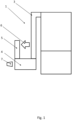
- FIG. 1 illustrates in particular an overview of a system for supplying stopper elements comprising three modules.
- the first module is a module for storing the stopper elements 2 which includes a hopper located in the lower part of the supply installation.
- This hopper consists of an enclosure into which the stopper elements are poured in bulk. This enclosure defines a volume of stopper elements making it possible in particular to define the autonomy of this supply device. A lower part of this enclosure provides access to the second module.
- the second module is a sorting module that includes a substantially vertical conveyor for raising the capping elements from the lower part, i.e. from the hopper to an upper part of the installation.
- This conveyor consists of an endless belt comprising cleats placed horizontally and customized to the capping element to be transported and sorted. These cleats most often have a U-shaped section, i.e. they consist of a bottom and two side walls. These cleats plunge into the hopper where the bulk elements are located, to collect them and raise them to the upper part of the installation.
- the stopper element consists of a face opposite which there is an opening and a wall making up the edge, so that it has a U-shaped section to match the shape of the neck on which it is affixed.
- plugging elements are supported by the cleats for which there is only one correct orientation, that is to say that the face of the plugging element is in contact with the bottom of the cleat while the poorly oriented elements fall back into the hopper.
- a hump is arranged at a certain height of the vertical conveyor. The difference in weight between the opening and the face is used to tilt and therefore sort the elements as they pass over the hump, more precisely, by dropping the elements whose face is not against the bottom of the cleat.
- these sorted elements When the sorted elements reach the top of the second module, these sorted elements in the form of a line are ejected either by a compressed air device or a mechanical system consisting of a finger movable in the direction of the length of the cleat. This finger passes between the cleats and pushes the line of elements out of the second module. At the exit of the ejection, these lines of sorted capping elements are sent to a third module.
- the third module is a device for supplying elements comprising a gravity chute 3 opening into a means 4 for processing the individual plugging elements where a vision means checks them. Then, they are taken up by an ascending conveyor branch 5 to be raised again towards a downstream workstation. During this elevation, the plugging elements identified as non-compliant are ejected by an ejection means 6.
- the lines of sorted stoppering elements are conveyed to the processing means 4 by the gravity chute 3 essentially oriented downwards. It is composed of guides capable of maintaining the orientation of the stoppering elements.
- the lines of sorted capping elements exit discontinuously or sequentially because the cleats are emptied one after the other while the workstation located downstream such as a capping machine or a sterilization device operates continuously.
- the capping elements are accumulated to form a continuous flow of capping elements all oriented.
- the stopper elements undergo processing, i.e. they are brought into step with respect to each other. In other words, they are conveyed with a distance with respect to each other, and are controlled by at least one vision means 7.
- This vision means can operate in different ways, either the vision means controls the plugging element at a specific position of the treatment means, or it controls the plugging element over a section of its movement as it circulates in the treatment means. In this case, the vision means seeks first the plugging element and then it controls it.
- the processing means and the vision means will be described in more detail in the description of the other figures.
- the plugging elements are taken care of, individually, by the ascending conveyor branch 5 which can ensure their elevation, for example to supply the workstation located downstream.
- This conveyor branch is parallel to the gravity chute 3.
- the ejection means is located at the level of the ascending conveyor branch 5. This height corresponds at least to the circulation of the ascending conveyor branch 5 during the time of carrying out the control of the capping element and the time of transferring the information to the ejection means 6.
- the fact of controlling capping elements by at least one vision means located in the processing means, that is to say in the lower part of the supply device 1, makes it possible to place the ejection means at a shorter distance than if the control had also been placed in the ascending conveyor branch as could have been the case in the state of the art.
- FIG. 2 illustrates an embodiment of the device 1 for supplying plugging elements and more particularly of the treatment means 4.
- This gravity chute is composed of a sliding base defining a reference plane on which the face of the elements 2 slides, conventionally, and of guides located on either side of the plugging elements. Opposite the sliding base is a wall preventing the elements from tilting. Still in a conventional orientation, the opening of the elements is opposite this wall.
- This treatment means comprises a referencing wheel 8 at the periphery of which are substantially radial surfaces 10 capable of conveying the plugging elements 2 one by one, an external guide 11 located in the continuity of one of the guides of the gravity chute 3 and parallel to the referencing wheel 8 in order to retain the elements, and to reference them between the surface 10 and the guide 11, as well as a sliding base located in the continuity of the base of the gravity chute 3 allowing the element to slide on it during its conveyance, and a wall being located opposite and parallel to the sliding base in order to prevent the elements 2 from tilting during their movement.
- the reference wheel 8 conveys the plugging elements in a clockwise direction.
- the sliding sole and/or the opposite wall can be transparent.
- the surfaces 10 are spaced from each other by a distance compatible with the treatment carried out subsequently, that is to say, control of the quality of the capping element, ejection time of the element, supply of the downstream work station such as a capping machine, sterilization station.
- the surfaces 10 may be in the form of notches surrounding the element and positioned around the periphery of the reference wheel.
- the guide 11 may have a discontinuity at its contact surface with the element 2.
- the contact surface corresponds to the height of the element 2 without a tamper-evident ring. Therefore, when the element 2 does not have a tamper-evident ring, it falls under the effect of its weight.
- this guide 11 may be made of a transparent material.
- the reference wheel 8 rotates clockwise relative to an axis A which is perpendicular to a plane defined by the reference wheel and this plane is substantially parallel to the plane defined by the sole of the gravity fall and to the plane defined by the sliding sole located at the level of the reference wheel.
- an ascending conveyor branch 5 which comprises an endless belt at the level of which there are cleats 12 which exert a thrust on the elements to drive them, a base on which the face of the elements slides, and a wall opposite the base in order to prevent any tilting of the element, as well as vertical guides 13 located on either side of the cleat 12 making it possible to prevent any tilting of the element.
- the element 2 is referenced between the cleat 12 and at least one of the guides 13, that is to say that the element is at the same time in contact with the cleat 12, one of the guides 13, the sole or the wall which thus define a volume of referencing and stability for the element 2.
- the ascending conveyor branch 5 has an ejection means 6 located at one of the guides 13.
- This ejection means comprises a compressed air nozzle or a mechanical device such as a jack and a recess in the guide 13 opposite the ejection means for passing the ejected element.
- the compressed air nozzle or the mechanical device such as a jack has the function of ejecting the element by exerting a thrust to destabilize it from its reference volume constituted by the cleat 12, one of the guides 13, and the sole or the wall.
- This element supply device comprises at least one vision means 7 located at the processing means 4 and more particularly, at the referencing wheel 8.
- the vision means is an image acquisition means such as a camera or a photographic device coupled to a control unit which controls the digitization of the element.
- This vision means can operate in different ways, either the vision means controls the plugging element at a precise point, therefore at a position referenced in the reference wheel, or the vision means controls the plugging element over a section of its movement when it circulates in the treatment means and in this case, the vision means first searches for the plugging element over a part of the section defined by the reference wheel and then the element is controlled.
- this element supply device 1 operates at a high rate, the control is carried out when the element 2 is referenced to a precise point in the reference wheel, that is to say, when the element is positioned between a surface 10 of the reference wheel 8 and the guide 11.
- the triggering of the control is synchronized between the reference wheel and the triggering of the vision means 7.
- the rotation of the reference wheel 8 induces the triggering of the vision means 7.
- This synchronization is implemented either by an encoder coupled to the motor for rotating the reference wheel 8, or by a sensor measuring the angle of rotation of the reference wheel.
- the vision means 7 is equipped with an objective which is placed in front relative to the level of the processing means 4 and more particularly opposite the reference wheel 8.
- the objective of the vision means 7 can be associated with a plane and this plane is substantially parallel to the plane defined by the reference wheel.
- the objective of the viewing means can be placed on one side or the other of the reference wheel in order to be able to check the face or the opening of the element 2 depending on the positioning of the objective.
- the sliding sole or the wall located opposite the sliding sole must be made of transparent material.
- this viewing means 7 has a lens that can be placed facing the side of the reference wheel 8 in order to be able to check the edge of the element 2 and more particularly in the case of caps equipped with a tamper-evident ring to check the presence or absence of this tamper-evident ring.
- the guide 11 peripheral to the reference wheel must be made of transparent material.
- the conveying of the elements 2 in the referencing wheel generates a rotation of said elements 2 on themselves.
- This rotation can be used to be able to control the edge of the element, with at least two vision means which can control the element at two different locations on the referencing wheel, for example one after the other.
- the element is ejected or not according to one of the criteria given to the control unit. Therefore, in the case of an ejection, the control unit actuates the ejection means 6 in order to remove only the element identified as undesirable, or even a few elements before and/or after.
- Synchronization is carried out between the processing means 4, the vision means 7 and the ejection means 6 to allow the ejection of the single element checked as non-compliant by the control unit, or even to eject very few elements, i.e. one or a few element(s) before and one or a few element(s) after the one checked as non-compliant.
- FIG 3 illustrates a second embodiment of the device 1 for supplying plugging elements and more particularly of the treatment means 4.
- This gravity chute is composed of a sliding base defining a reference plane and on which the face of the elements 2 conventionally slides, guides located on either side of the plugging elements, and opposite the sliding base, a wall preventing the elements from tilting. In a conventional orientation, the opening of the elements is opposite this wall.
- This treatment means comprises a reference wheel 8 and a return wheel 9.
- the referencing wheel 8 comprises surfaces 10 at its periphery that are substantially radial and capable of conveying the plugging elements 2 one by one.
- An external guide 11 is located in the continuity of one of the guides of the gravity chute 3 and parallel to the referencing wheel 8 in order to retain the elements, to reference them between the surface 10 and the guide 11.
- a sliding sole is located in the continuity of the sole of the gravity chute 3 allowing the element to slide on it during its conveyance.
- a wall is located opposite and parallel to the sliding sole in order to prevent the elements 2 from tilting during their movements.
- the surfaces 10 are spaced apart from each other by a distance compatible with the treatment carried out subsequently, that is to say, quality control of the capping elements, supply of the downstream work station such as a capping machine, and sterilization station for the element.
- the reference wheel 8 rotates counterclockwise relative to an axis B which is perpendicular to a plane defined by the reference wheel. This plane is substantially parallel to the sole of the gravity chute.
- the return wheel 9 has a structure similar to the referencing wheel 8, that is to say that the return wheel 9 comprises at its periphery substantially radial surfaces 10 and capable of conveying the plugging elements 2 one by one.
- An external guide 14 is located parallel to the circumference of the return wheel 9 in order to retain the elements, to reference them between the surface 10 and the guide 14.
- a sliding sole is located in the continuity of the sole of the referencing wheel allowing the element to slide on it during its conveying.
- a wall is located opposite and parallel to the sliding sole in order to prevent the elements 2 from tilting during their movement.
- the return wheel has the function of increasing the transport time and therefore the time available for control compared to the solution described in the first embodiment.
- the ascending conveyor branch 5 and the ejection means 6 have the same structure as that described previously for the figure 2 .
- FIG 4 illustrates a third embodiment of the device 1 for supplying plugging elements and more particularly of the treatment means 4.
- the return wheel 9 may be a wheel which is used to engage a belt which is provided with cleats between which there is each element 2.
- cleats comprise a surface which has the same function as the surface 10 of the embodiment described previously, that is to say that said surface is capable of conveying the elements 2 one by one.
- the vision means can operate in different ways: either the vision means controls the plugging element at a specific position of the treatment means, or it controls the plugging element over a section of its movement as it travels through the treatment means. In this case, the vision means first searches for the plugging element and then controls it.
- the triggering of the control is synchronized between the reference wheel and/or the return wheel and the triggering of the vision means 7.
- the rotation of the reference wheel 8 and/or the return wheel 9 induces the triggering of the vision means 7.
- This synchronization is implemented either by an encoder coupled to the motor for rotating the reference wheel 8 and/or the return wheel 9, or by a sensor measuring the rotation angle of one of the wheels.
- the viewing means 7 is equipped with a lens which is placed in front relative to the level of the processing means 4 and more particularly opposite one of the wheels.
- the lens of the viewing means 7 can be associated with a plane and this plane is substantially parallel to the plane defined by one of the wheels, that is to say, the reference wheel and/or the return wheel 9.
- the objective of the viewing means can be placed on one side or the other of the reference wheel in order to be able to control the face or the opening of the element 2 depending on the positioning of the objective.
- the viewing means 7 can be placed in front of or behind the processing means 4.
- the sliding sole and/or the wall located opposite the sliding sole must be made of transparent material.
- this vision means 7 has a lens which can be placed opposite the side of one of the wheels in order to be able to check the edge of the element 2 and more particularly, in the case of caps equipped with a tamper-evident ring, check the presence or absence of this tamper-evident ring.
- guide 11 and/or guide 14 must be made of transparent material.
- the conveying of the elements 2 in the wheels 8, 9 generates a rotation of said elements 2 on themselves.
- This rotation can be used to inspect the edge of the element, with at least two vision means 6 which can control the element at two different locations on the wheels.
- the element is ejected or not according to one of the criteria set in the control unit. Therefore, in the case of an ejection, the control unit actuates the ejection means 6 in order to remove only the element checked as undesirable or at least very few elements before or after.
Landscapes
- Engineering & Computer Science (AREA)
- Mechanical Engineering (AREA)
- Specific Conveyance Elements (AREA)
- Branching, Merging, And Special Transfer Between Conveyors (AREA)
- Feeding Of Articles To Conveyors (AREA)
- Sorting Of Articles (AREA)
- Attitude Control For Articles On Conveyors (AREA)
Claims (9)
- Vorrichtung (1) zur Bereitstellung von sortierten Elementen (2) zum Beschicken einer stromabwärtigen Arbeitsstation, wobei die Vorrichtung Folgendes umfasst: ein Fallrohr (3), das die Elemente zuführt, ein Mittel (4) zur stückweisen Verarbeitung, das die Elemente aus dem Fallrohr aufnimmt, einen aufsteigenden Transportzweig (5), der sich vom Verarbeitungsmittel aus erstreckt und von diesem die Elemente (2) empfängt, und ein Auswurfmittel (6), das sich am aufsteigenden Transportzweig befindet, mindestens ein Sichtmittel (7), das dazu positioniert ist, die Elemente am Verarbeitungsmittel (4) zu kontrollieren, beispielsweise eine Kamera, und eine Steuereinheit, die das Sichtmittel (7) in Abhängigkeit von einem Signal, das den Fortschritt des Verarbeitungsmittels (4) darstellt, auslöst und das die Betätigung des Auswurfmittels (6) auslöst, wenn durch das Sichtmittel (7) ein Fehler festgestellt wird, wobei der Betrieb des Sichtmittels (7) mit dem des Verarbeitungsmittels synchronisiert ist.
- Bereitstellungsvorrichtung nach Anspruch 1, dadurch gekennzeichnet, dass sich das Sichtmittel (7) an der Front des Verarbeitungsmittels (4) befindet, um eine der Seiten des Elements (2) zu kontrollieren.
- Bereitstellungsvorrichtung nach einem der Ansprüche 1 oder 2, dadurch gekennzeichnet, dass sich das Sichtmittel (7) an einer Seite des Verarbeitungsmittels (4) befindet, um einen Teil der Kante des Elements zu kontrollieren.
- Bereitstellungsvorrichtung nach einem der Ansprüche 1 bis 3, dadurch gekennzeichnet, dass das Verarbeitungsmittel (4) ein Referenzierungsrad (8) umfasst, das die Elemente stückweise einem Rückführrad (9) zuführt, und dass das Referenzierungsrad (8) und das Rückführrad (9) mit Referenzierungsflächen (10) ausgestattet sind, die einen Schub auf das Element ausüben, um es auszurichten und zu bewegen, wobei das Rückführrad (9) zum Verarbeitungsmittel (4) gehört.
- Bereitstellungsvorrichtung nach einem der Ansprüche 1 bis 4, dadurch gekennzeichnet, dass das Verarbeitungsmittel (4) ein Referenzierungsrad (8) umfasst, das die Elemente einem am Rückführrad (9) montierten Riemen zuführt, wobei der Riemen und das Referenzierungsrad mit Referenzierungsflächen (10) ausgestattet sind, die einen Schub auf das Element ausüben, um es auszurichten und zu bewegen, wobei das Rückführrad (9) zum Verarbeitungsmittel (4) gehört.
- Verfahren zur Bereitstellung von sortierten Elementen (2) zum Beschicken einer stromabwärtigen Arbeitsstation, wobei das Verfahren eine Abfolge von Schritten umfasst, die im Wesentlichen aus Folgendem bestehen:Zuführen der Elemente (2) in einer einreihigen Kolonne mit Hilfe eines Fallrohrs zu einem Mittel (4) zur stückweisen Verarbeitung,anschließend Befördern und Ausrichten der Elemente mit Hilfe des Mittels (4) zur stückweisen Verarbeitung,anschließend stückweises Entnehmen der Elemente in einen aufsteigenden Transportzweig (5),wobei das Verfahren ferner einen Schritt des Kontrollierens der Elemente durch mindestens ein Sichtmittel (7) am Mittel (4) zur stückweisen Verarbeitung und einen Schritt des Auswerfens des Elements in Abhängigkeit vom Ergebnis des Kontrollschritts umfasst, wobei der Auswurfschritt durch ein am aufsteigenden Transportzweig (5) befindliches Auswurfmittel (6) erfolgt.
- Verfahren nach Anspruch 6, dadurch gekennzeichnet, dass der Schritt des Kontrollierens des Elements durch ein Sichtmittel (7) erfolgt, das mit der Bewegung des Verschlusselements (2) im Verarbeitungsmittel (4) synchronisiert ist.
- Verfahren nach einem der Ansprüche 6 oder 7, dadurch gekennzeichnet, dass ein Kontrollschritt mit dem an einer Front des Verarbeitungsmittels (4) befindlichen Sichtmittel (7) durchgeführt wird, um eine Seite des Verschlusselements (2) zu kontrollieren.
- Verfahren nach einem der Ansprüche 6 bis 8, dadurch gekennzeichnet, dass ein Kontrollschritt mit dem an einer Seite des Verarbeitungsmittels (4) befindlichen Sichtmittel (7) durchgeführt wird, um einen Teil der Kante des Elements (2) zu kontrollieren.
Applications Claiming Priority (1)
| Application Number | Priority Date | Filing Date | Title |
|---|---|---|---|
| FR1751863A FR3063717B1 (fr) | 2017-03-08 | 2017-03-08 | Dispositif et methode de fourniture fiable d'elements de bouchage conformes |
Publications (3)
| Publication Number | Publication Date |
|---|---|
| EP3372539A1 EP3372539A1 (de) | 2018-09-12 |
| EP3372539B1 true EP3372539B1 (de) | 2024-11-06 |
| EP3372539B8 EP3372539B8 (de) | 2024-12-11 |
Family
ID=58645286
Family Applications (1)
| Application Number | Title | Priority Date | Filing Date |
|---|---|---|---|
| EP18158155.4A Active EP3372539B8 (de) | 2017-03-08 | 2018-02-22 | Vorrichtung und methode der zuverlässigen versorgung mit konformen verschlusselementen |
Country Status (7)
| Country | Link |
|---|---|
| US (1) | US10899559B2 (de) |
| EP (1) | EP3372539B8 (de) |
| CN (1) | CN108569543B (de) |
| CA (1) | CA2995764A1 (de) |
| FR (1) | FR3063717B1 (de) |
| HU (1) | HUE070798T2 (de) |
| MX (1) | MX395172B (de) |
Families Citing this family (4)
| Publication number | Priority date | Publication date | Assignee | Title |
|---|---|---|---|---|
| FR3086652B1 (fr) | 2018-09-28 | 2020-10-23 | Gebo Packaging Solutions France | Dispositif et procede de fourniture d'elements de bouchage tries |
| CN112170215B (zh) * | 2020-09-22 | 2023-03-31 | 上海兹懋仪器科技有限公司 | 一种螺栓生产用废品检测机构 |
| CN113210288A (zh) * | 2021-05-08 | 2021-08-06 | 重庆工业职业技术学院 | 一种燕窝生产用智能分级装置 |
| DE102023122563A1 (de) * | 2023-08-23 | 2025-02-27 | Khs Gmbh | Behältertransportvorrichtung zum Transport von Behältern |
Citations (1)
| Publication number | Priority date | Publication date | Assignee | Title |
|---|---|---|---|---|
| US4741428A (en) * | 1983-03-04 | 1988-05-03 | Takeda Chemical Industries, Ltd. | Supply hopper assembly |
Family Cites Families (18)
| Publication number | Priority date | Publication date | Assignee | Title |
|---|---|---|---|---|
| US2756862A (en) * | 1952-02-18 | 1956-07-31 | Fmc Corp | Article feeding mechanism |
| US3193078A (en) * | 1963-01-18 | 1965-07-06 | Emhart Corp | Article divider for conveyors |
| US3587920A (en) * | 1969-03-19 | 1971-06-28 | Medical Supply Co | Mechanisms for feeding and dropping elongated tubular bodies and caps |
| US5586637A (en) | 1994-02-22 | 1996-12-24 | Aidlin; Samuel S. | Variable angle conveyor assembly with stepped cleat |
| US5394972A (en) | 1994-02-22 | 1995-03-07 | Aidlin; Stephen H. | Variable angle conveyor assembly |
| JP3335517B2 (ja) * | 1995-12-25 | 2002-10-21 | ワイケイケイ株式会社 | 物品整送装置 |
| US7222719B2 (en) * | 2002-11-01 | 2007-05-29 | Reagent Chemical & Research, Inc. | Container transport and organizing apparatus for use in manufacturing operations and method thereof |
| CN1529165A (zh) * | 2003-09-25 | 2004-09-15 | 谢森林 | 全自动瓶装药剂检测机 |
| US7364043B2 (en) * | 2003-12-30 | 2008-04-29 | Zen Voce Manufacturing Pte Ltd | Fastener inspection system |
| KR100849003B1 (ko) * | 2004-04-13 | 2008-07-30 | 티디케이가부시기가이샤 | 칩 부품 반송 방법 및 장치, 및 외관 검사 방법 및 장치 |
| FR2876990B1 (fr) | 2004-10-25 | 2007-01-12 | Sidel Sas | Perfectionnement aux machines d'appret utilisees pour orienter des objets en vue de l'alimentation d'une chaine de preparation de produits comportant lesdits objets |
| JP2010101691A (ja) * | 2008-10-22 | 2010-05-06 | Kyodo Printing Co Ltd | 樹脂成型品の外観検査装置及びその外観検査方法 |
| FR2961801B1 (fr) | 2010-06-29 | 2013-11-08 | Sidel Participations | Dispositif de preparation d'elements de bouchage |
| DE102012216163B4 (de) * | 2012-01-11 | 2017-03-09 | Robert Bosch Gmbh | Vorrichtung zum Zuführen von Kappen mit Überwachungssystem |
| CN202519013U (zh) * | 2012-03-28 | 2012-11-07 | 杭州胡庆余堂药业有限公司 | 液体灌装生产线中药瓶的自动排列装置 |
| CN103508201B (zh) * | 2013-09-10 | 2016-01-20 | 上海东富龙科技股份有限公司 | 一种用于灯检机的安瓿瓶出料装置 |
| CN103979304A (zh) * | 2014-05-13 | 2014-08-13 | 欧均灿 | 卡盘式电池生产线输送装置 |
| CA2971367C (fr) | 2014-12-30 | 2023-01-17 | Gebo Packaging Solutions France | Dispositif et methode de fourniture fiable d'elements de bouchage conformes |
-
2017
- 2017-03-08 FR FR1751863A patent/FR3063717B1/fr active Active
-
2018
- 2018-02-20 CA CA2995764A patent/CA2995764A1/fr active Pending
- 2018-02-22 HU HUE18158155A patent/HUE070798T2/hu unknown
- 2018-02-22 EP EP18158155.4A patent/EP3372539B8/de active Active
- 2018-03-07 US US15/914,704 patent/US10899559B2/en active Active
- 2018-03-07 MX MX2018002888A patent/MX395172B/es unknown
- 2018-03-08 CN CN201810189194.2A patent/CN108569543B/zh active Active
Patent Citations (1)
| Publication number | Priority date | Publication date | Assignee | Title |
|---|---|---|---|---|
| US4741428A (en) * | 1983-03-04 | 1988-05-03 | Takeda Chemical Industries, Ltd. | Supply hopper assembly |
Also Published As
| Publication number | Publication date |
|---|---|
| BR102018004530A2 (pt) | 2018-12-04 |
| MX395172B (es) | 2025-03-25 |
| MX2018002888A (es) | 2018-11-09 |
| CN108569543B (zh) | 2022-01-11 |
| FR3063717A1 (fr) | 2018-09-14 |
| CA2995764A1 (fr) | 2018-09-08 |
| US20190276247A1 (en) | 2019-09-12 |
| CN108569543A (zh) | 2018-09-25 |
| HUE070798T2 (hu) | 2025-07-28 |
| EP3372539B8 (de) | 2024-12-11 |
| FR3063717B1 (fr) | 2021-07-23 |
| US10899559B2 (en) | 2021-01-26 |
| EP3372539A1 (de) | 2018-09-12 |
Similar Documents
| Publication | Publication Date | Title |
|---|---|---|
| EP3240744B1 (de) | Vorrichtung und verfahren zur zuverlässigen ausgabe von geformten stopperelementen | |
| EP1805092B1 (de) | Förderband für eine fertigungsmaschine zur ausrichtung von objekten | |
| EP3372539A1 (de) | Vorrichtung und methode der zuverlässigen versorgung mit konformen verschlusselementen | |
| EP1814811B1 (de) | Verbesserung von endbehandlungsmaschinen, die zur ausrichtung von objekten verwendet werden | |
| EP2066261B2 (de) | Gerät zum befüllen von besamungsröhrchen | |
| WO2016107655A1 (fr) | Dispositif et méthode de fourniture d'éléments orientés | |
| EP3828107B1 (de) | Sortieranlage für artikeln wie pakete mit einem system zum kontrollieren der position der artikeln durch die detektion der kontur | |
| CH632090A5 (fr) | Machine de controle automatique de l'efficacite des fermetures de recipients. | |
| FR2538343A1 (fr) | Dispositif pour alimenter en cigarettes la ligne d'enveloppement d'une machine a empaqueter les cigarettes | |
| EP3856675B1 (de) | Vorrichtung und verfahren zum bereitstellen von sortierten stopfenelementen | |
| EP2920092B1 (de) | Maschine zum verteilen von schüttgut | |
| EP3450028B1 (de) | Vorrichtung und verfahren zum sortieren von schachteln | |
| CA3141260A1 (fr) | Dispositif de fourniture d'elements de bouchage tries | |
| WO2019002744A1 (fr) | Procede et dispositif de gestion d'un module de triage d'organes | |
| FR3098738A1 (fr) | Installation pour l’évaluation de la qualité d’un lot de produits alimentaires et procédé pour sa mise en œuvre | |
| FR2759668A1 (fr) | Dispositif de distribution de comprimes et gelules a lyre pour machine de mise sous blister a avance discontinue et procede utilisant le dispositif | |
| EP3199478A1 (de) | Vorrichtung und methode zur kontrollierten förderung | |
| FR2780383A1 (fr) | Dispositif de deconditionnement d'articles garnissant des tubes cylindriques contenus dans des etuis | |
| FR2600038A1 (fr) | Procede pour la detection de recipients vides ou incorrectement remplis par un produit solide, notamment alimentaire, dans une machine remplisseuse a carrousel et systeme pour la mise en oeuvre de ce procede. | |
| FR3122586A1 (fr) | Système et procédé de tri particulaire, et installation et procédé de tri et de caractérisation particulaire associés | |
| EP0401103A1 (de) | Vorrichtung zur selbsttätigen Verwaltung von Füllfehlern in Verpackungsmaschinen | |
| WO2006072727A1 (fr) | Procede et dispositif de nettoyage et d'orientation de bouchons de fermeture de bouteilles | |
| FR2663608A1 (fr) | Dispositif pour la mise en barquettes de produits alimentaires calibres. | |
| BR102018004530B1 (pt) | Dispositivo e processo de fornecimento de elementos | |
| WO1997006066A1 (fr) | Dispositif pour l'extraction du contenu des aveoles d'une plaquette-emballage dans une installation de conditionnement |
Legal Events
| Date | Code | Title | Description |
|---|---|---|---|
| PUAI | Public reference made under article 153(3) epc to a published international application that has entered the european phase |
Free format text: ORIGINAL CODE: 0009012 |
|
| STAA | Information on the status of an ep patent application or granted ep patent |
Free format text: STATUS: THE APPLICATION HAS BEEN PUBLISHED |
|
| AK | Designated contracting states |
Kind code of ref document: A1 Designated state(s): AL AT BE BG CH CY CZ DE DK EE ES FI FR GB GR HR HU IE IS IT LI LT LU LV MC MK MT NL NO PL PT RO RS SE SI SK SM TR |
|
| AX | Request for extension of the european patent |
Extension state: BA ME |
|
| STAA | Information on the status of an ep patent application or granted ep patent |
Free format text: STATUS: REQUEST FOR EXAMINATION WAS MADE |
|
| 17P | Request for examination filed |
Effective date: 20190305 |
|
| RBV | Designated contracting states (corrected) |
Designated state(s): AL AT BE BG CH CY CZ DE DK EE ES FI FR GB GR HR HU IE IS IT LI LT LU LV MC MK MT NL NO PL PT RO RS SE SI SK SM TR |
|
| STAA | Information on the status of an ep patent application or granted ep patent |
Free format text: STATUS: EXAMINATION IS IN PROGRESS |
|
| 17Q | First examination report despatched |
Effective date: 20211112 |
|
| GRAP | Despatch of communication of intention to grant a patent |
Free format text: ORIGINAL CODE: EPIDOSNIGR1 |
|
| STAA | Information on the status of an ep patent application or granted ep patent |
Free format text: STATUS: GRANT OF PATENT IS INTENDED |
|
| INTG | Intention to grant announced |
Effective date: 20240531 |
|
| GRAS | Grant fee paid |
Free format text: ORIGINAL CODE: EPIDOSNIGR3 |
|
| GRAA | (expected) grant |
Free format text: ORIGINAL CODE: 0009210 |
|
| STAA | Information on the status of an ep patent application or granted ep patent |
Free format text: STATUS: THE PATENT HAS BEEN GRANTED |
|
| REG | Reference to a national code |
Ref country code: DE Ref legal event code: R081 Ref document number: 602018076182 Country of ref document: DE Owner name: SIDEL PARTICIPATIONS, FR Free format text: FORMER OWNER: GEBO PACKAGING SOLUTIONS FRANCE, REICHSTETT, FR |
|
| AK | Designated contracting states |
Kind code of ref document: B1 Designated state(s): AL AT BE BG CH CY CZ DE DK EE ES FI FR GB GR HR HU IE IS IT LI LT LU LV MC MK MT NL NO PL PT RO RS SE SI SK SM TR |
|
| REG | Reference to a national code |
Ref country code: GB Ref legal event code: FG4D Free format text: NOT ENGLISH |
|
| RAP2 | Party data changed (patent owner data changed or rights of a patent transferred) |
Owner name: SIDEL PARTICIPATIONS |
|
| REG | Reference to a national code |
Ref country code: CH Ref legal event code: PK Free format text: RECTIFICATION B8 Ref country code: CH Ref legal event code: EP |
|
| P01 | Opt-out of the competence of the unified patent court (upc) registered |
Free format text: CASE NUMBER: APP_56310/2024 Effective date: 20241015 |
|
| REG | Reference to a national code |
Ref country code: DE Ref legal event code: R096 Ref document number: 602018076182 Country of ref document: DE |
|
| REG | Reference to a national code |
Ref country code: IE Ref legal event code: FG4D Free format text: LANGUAGE OF EP DOCUMENT: FRENCH |
|
| REG | Reference to a national code |
Ref country code: SE Ref legal event code: TRGR |
|
| REG | Reference to a national code |
Ref country code: LT Ref legal event code: MG9D |
|
| REG | Reference to a national code |
Ref country code: NL Ref legal event code: MP Effective date: 20241106 |
|
| PG25 | Lapsed in a contracting state [announced via postgrant information from national office to epo] |
Ref country code: HR Free format text: LAPSE BECAUSE OF FAILURE TO SUBMIT A TRANSLATION OF THE DESCRIPTION OR TO PAY THE FEE WITHIN THE PRESCRIBED TIME-LIMIT Effective date: 20241106 Ref country code: IS Free format text: LAPSE BECAUSE OF FAILURE TO SUBMIT A TRANSLATION OF THE DESCRIPTION OR TO PAY THE FEE WITHIN THE PRESCRIBED TIME-LIMIT Effective date: 20250306 Ref country code: PT Free format text: LAPSE BECAUSE OF FAILURE TO SUBMIT A TRANSLATION OF THE DESCRIPTION OR TO PAY THE FEE WITHIN THE PRESCRIBED TIME-LIMIT Effective date: 20250306 |
|
| PG25 | Lapsed in a contracting state [announced via postgrant information from national office to epo] |
Ref country code: FI Free format text: LAPSE BECAUSE OF FAILURE TO SUBMIT A TRANSLATION OF THE DESCRIPTION OR TO PAY THE FEE WITHIN THE PRESCRIBED TIME-LIMIT Effective date: 20241106 Ref country code: NL Free format text: LAPSE BECAUSE OF FAILURE TO SUBMIT A TRANSLATION OF THE DESCRIPTION OR TO PAY THE FEE WITHIN THE PRESCRIBED TIME-LIMIT Effective date: 20241106 |
|
| PG25 | Lapsed in a contracting state [announced via postgrant information from national office to epo] |
Ref country code: BG Free format text: LAPSE BECAUSE OF FAILURE TO SUBMIT A TRANSLATION OF THE DESCRIPTION OR TO PAY THE FEE WITHIN THE PRESCRIBED TIME-LIMIT Effective date: 20241106 |
|
| PG25 | Lapsed in a contracting state [announced via postgrant information from national office to epo] |
Ref country code: ES Free format text: LAPSE BECAUSE OF FAILURE TO SUBMIT A TRANSLATION OF THE DESCRIPTION OR TO PAY THE FEE WITHIN THE PRESCRIBED TIME-LIMIT Effective date: 20241106 |
|
| PG25 | Lapsed in a contracting state [announced via postgrant information from national office to epo] |
Ref country code: NO Free format text: LAPSE BECAUSE OF FAILURE TO SUBMIT A TRANSLATION OF THE DESCRIPTION OR TO PAY THE FEE WITHIN THE PRESCRIBED TIME-LIMIT Effective date: 20250206 |
|
| PG25 | Lapsed in a contracting state [announced via postgrant information from national office to epo] |
Ref country code: LV Free format text: LAPSE BECAUSE OF FAILURE TO SUBMIT A TRANSLATION OF THE DESCRIPTION OR TO PAY THE FEE WITHIN THE PRESCRIBED TIME-LIMIT Effective date: 20241106 Ref country code: GR Free format text: LAPSE BECAUSE OF FAILURE TO SUBMIT A TRANSLATION OF THE DESCRIPTION OR TO PAY THE FEE WITHIN THE PRESCRIBED TIME-LIMIT Effective date: 20250207 |
|
| PG25 | Lapsed in a contracting state [announced via postgrant information from national office to epo] |
Ref country code: PL Free format text: LAPSE BECAUSE OF FAILURE TO SUBMIT A TRANSLATION OF THE DESCRIPTION OR TO PAY THE FEE WITHIN THE PRESCRIBED TIME-LIMIT Effective date: 20241106 |
|
| PG25 | Lapsed in a contracting state [announced via postgrant information from national office to epo] |
Ref country code: RS Free format text: LAPSE BECAUSE OF FAILURE TO SUBMIT A TRANSLATION OF THE DESCRIPTION OR TO PAY THE FEE WITHIN THE PRESCRIBED TIME-LIMIT Effective date: 20250206 |
|
| PG25 | Lapsed in a contracting state [announced via postgrant information from national office to epo] |
Ref country code: SM Free format text: LAPSE BECAUSE OF FAILURE TO SUBMIT A TRANSLATION OF THE DESCRIPTION OR TO PAY THE FEE WITHIN THE PRESCRIBED TIME-LIMIT Effective date: 20241106 |
|
| PG25 | Lapsed in a contracting state [announced via postgrant information from national office to epo] |
Ref country code: DK Free format text: LAPSE BECAUSE OF FAILURE TO SUBMIT A TRANSLATION OF THE DESCRIPTION OR TO PAY THE FEE WITHIN THE PRESCRIBED TIME-LIMIT Effective date: 20241106 |
|
| PGFP | Annual fee paid to national office [announced via postgrant information from national office to epo] |
Ref country code: HU Payment date: 20250211 Year of fee payment: 8 |
|
| PG25 | Lapsed in a contracting state [announced via postgrant information from national office to epo] |
Ref country code: RO Free format text: LAPSE BECAUSE OF FAILURE TO SUBMIT A TRANSLATION OF THE DESCRIPTION OR TO PAY THE FEE WITHIN THE PRESCRIBED TIME-LIMIT Effective date: 20241106 |
|
| PG25 | Lapsed in a contracting state [announced via postgrant information from national office to epo] |
Ref country code: SK Free format text: LAPSE BECAUSE OF FAILURE TO SUBMIT A TRANSLATION OF THE DESCRIPTION OR TO PAY THE FEE WITHIN THE PRESCRIBED TIME-LIMIT Effective date: 20241106 |
|
| PG25 | Lapsed in a contracting state [announced via postgrant information from national office to epo] |
Ref country code: CZ Free format text: LAPSE BECAUSE OF FAILURE TO SUBMIT A TRANSLATION OF THE DESCRIPTION OR TO PAY THE FEE WITHIN THE PRESCRIBED TIME-LIMIT Effective date: 20241106 |
|
| REG | Reference to a national code |
Ref country code: HU Ref legal event code: AG4A Ref document number: E070798 Country of ref document: HU |
|
| REG | Reference to a national code |
Ref country code: DE Ref legal event code: R097 Ref document number: 602018076182 Country of ref document: DE |
|
| PLBE | No opposition filed within time limit |
Free format text: ORIGINAL CODE: 0009261 |
|
| STAA | Information on the status of an ep patent application or granted ep patent |
Free format text: STATUS: NO OPPOSITION FILED WITHIN TIME LIMIT |
|
| PG25 | Lapsed in a contracting state [announced via postgrant information from national office to epo] |
Ref country code: MC Free format text: LAPSE BECAUSE OF FAILURE TO SUBMIT A TRANSLATION OF THE DESCRIPTION OR TO PAY THE FEE WITHIN THE PRESCRIBED TIME-LIMIT Effective date: 20241106 |
|
| REG | Reference to a national code |
Ref country code: CH Ref legal event code: PL |
|
| 26N | No opposition filed |
Effective date: 20250807 |
|
| PG25 | Lapsed in a contracting state [announced via postgrant information from national office to epo] |
Ref country code: LU Free format text: LAPSE BECAUSE OF NON-PAYMENT OF DUE FEES Effective date: 20250222 |
|
| PG25 | Lapsed in a contracting state [announced via postgrant information from national office to epo] |
Ref country code: CH Free format text: LAPSE BECAUSE OF NON-PAYMENT OF DUE FEES Effective date: 20250228 |
|
| REG | Reference to a national code |
Ref country code: BE Ref legal event code: MM Effective date: 20250228 |
|
| PG25 | Lapsed in a contracting state [announced via postgrant information from national office to epo] |
Ref country code: BE Free format text: LAPSE BECAUSE OF NON-PAYMENT OF DUE FEES Effective date: 20250228 |
|
| PG25 | Lapsed in a contracting state [announced via postgrant information from national office to epo] |
Ref country code: IE Free format text: LAPSE BECAUSE OF NON-PAYMENT OF DUE FEES Effective date: 20250222 |
|
| REG | Reference to a national code |
Ref country code: AT Ref legal event code: UEP Ref document number: 1739177 Country of ref document: AT Kind code of ref document: T Effective date: 20241106 |
|
| PGFP | Annual fee paid to national office [announced via postgrant information from national office to epo] |
Ref country code: SE Payment date: 20260121 Year of fee payment: 9 |
|
| PGFP | Annual fee paid to national office [announced via postgrant information from national office to epo] |
Ref country code: GB Payment date: 20260122 Year of fee payment: 9 |
|
| PGFP | Annual fee paid to national office [announced via postgrant information from national office to epo] |
Ref country code: DE Payment date: 20260121 Year of fee payment: 9 |
|
| PGFP | Annual fee paid to national office [announced via postgrant information from national office to epo] |
Ref country code: AT Payment date: 20260123 Year of fee payment: 9 |
|
| PGFP | Annual fee paid to national office [announced via postgrant information from national office to epo] |
Ref country code: IT Payment date: 20260121 Year of fee payment: 9 |
|
| PGFP | Annual fee paid to national office [announced via postgrant information from national office to epo] |
Ref country code: FR Payment date: 20260121 Year of fee payment: 9 |