EP3856675B1 - Vorrichtung und verfahren zum bereitstellen von sortierten stopfenelementen - Google Patents
Vorrichtung und verfahren zum bereitstellen von sortierten stopfenelementen Download PDFInfo
- Publication number
- EP3856675B1 EP3856675B1 EP19773444.5A EP19773444A EP3856675B1 EP 3856675 B1 EP3856675 B1 EP 3856675B1 EP 19773444 A EP19773444 A EP 19773444A EP 3856675 B1 EP3856675 B1 EP 3856675B1
- Authority
- EP
- European Patent Office
- Prior art keywords
- elements
- sections
- vision
- referencing
- provider device
- Prior art date
- Legal status (The legal status is an assumption and is not a legal conclusion. Google has not performed a legal analysis and makes no representation as to the accuracy of the status listed.)
- Active
Links
Images

Classifications
-
- B—PERFORMING OPERATIONS; TRANSPORTING
- B67—OPENING, CLOSING OR CLEANING BOTTLES, JARS OR SIMILAR CONTAINERS; LIQUID HANDLING
- B67B—APPLYING CLOSURE MEMBERS TO BOTTLES JARS, OR SIMILAR CONTAINERS; OPENING CLOSED CONTAINERS
- B67B3/00—Closing bottles, jars or similar containers by applying caps
- B67B3/02—Closing bottles, jars or similar containers by applying caps by applying flanged caps, e.g. crown caps, and securing by deformation of flanges
- B67B3/06—Feeding caps to capping heads
- B67B3/064—Feeding caps to capping heads from a hopper
- B67B3/0645—Feeding caps to capping heads from a hopper with means for orientating the caps to a position ready to be applied to the container
-
- B—PERFORMING OPERATIONS; TRANSPORTING
- B65—CONVEYING; PACKING; STORING; HANDLING THIN OR FILAMENTARY MATERIAL
- B65G—TRANSPORT OR STORAGE DEVICES, e.g. CONVEYORS FOR LOADING OR TIPPING, SHOP CONVEYOR SYSTEMS OR PNEUMATIC TUBE CONVEYORS
- B65G43/00—Control devices, e.g. for safety, warning or fault-correcting
- B65G43/08—Control devices operated by article or material being fed, conveyed or discharged
-
- B—PERFORMING OPERATIONS; TRANSPORTING
- B65—CONVEYING; PACKING; STORING; HANDLING THIN OR FILAMENTARY MATERIAL
- B65G—TRANSPORT OR STORAGE DEVICES, e.g. CONVEYORS FOR LOADING OR TIPPING, SHOP CONVEYOR SYSTEMS OR PNEUMATIC TUBE CONVEYORS
- B65G47/00—Article or material-handling devices associated with conveyors; Methods employing such devices
- B65G47/02—Devices for feeding articles or materials to conveyors
- B65G47/04—Devices for feeding articles or materials to conveyors for feeding articles
- B65G47/12—Devices for feeding articles or materials to conveyors for feeding articles from disorderly-arranged article piles or from loose assemblages of articles
- B65G47/14—Devices for feeding articles or materials to conveyors for feeding articles from disorderly-arranged article piles or from loose assemblages of articles arranging or orientating the articles by mechanical or pneumatic means during feeding
-
- B—PERFORMING OPERATIONS; TRANSPORTING
- B65—CONVEYING; PACKING; STORING; HANDLING THIN OR FILAMENTARY MATERIAL
- B65G—TRANSPORT OR STORAGE DEVICES, e.g. CONVEYORS FOR LOADING OR TIPPING, SHOP CONVEYOR SYSTEMS OR PNEUMATIC TUBE CONVEYORS
- B65G47/00—Article or material-handling devices associated with conveyors; Methods employing such devices
- B65G47/22—Devices influencing the relative position or the attitude of articles during transit by conveyors
- B65G47/24—Devices influencing the relative position or the attitude of articles during transit by conveyors orientating the articles
- B65G47/256—Devices influencing the relative position or the attitude of articles during transit by conveyors orientating the articles removing incorrectly orientated articles
-
- B—PERFORMING OPERATIONS; TRANSPORTING
- B67—OPENING, CLOSING OR CLEANING BOTTLES, JARS OR SIMILAR CONTAINERS; LIQUID HANDLING
- B67B—APPLYING CLOSURE MEMBERS TO BOTTLES JARS, OR SIMILAR CONTAINERS; OPENING CLOSED CONTAINERS
- B67B3/00—Closing bottles, jars or similar containers by applying caps
- B67B3/26—Applications of control, warning, or safety devices in capping machinery
- B67B3/262—Devices for controlling the caps
- B67B3/264—Devices for controlling the caps positioning of the caps
-
- G—PHYSICS
- G01—MEASURING; TESTING
- G01N—INVESTIGATING OR ANALYSING MATERIALS BY DETERMINING THEIR CHEMICAL OR PHYSICAL PROPERTIES
- G01N21/00—Investigating or analysing materials by the use of optical means, i.e. using sub-millimetre waves, infrared, visible or ultraviolet light
- G01N21/84—Systems specially adapted for particular applications
- G01N21/88—Investigating the presence of flaws or contamination
- G01N21/8806—Specially adapted optical and illumination features
-
- G—PHYSICS
- G01—MEASURING; TESTING
- G01N—INVESTIGATING OR ANALYSING MATERIALS BY DETERMINING THEIR CHEMICAL OR PHYSICAL PROPERTIES
- G01N21/00—Investigating or analysing materials by the use of optical means, i.e. using sub-millimetre waves, infrared, visible or ultraviolet light
- G01N21/84—Systems specially adapted for particular applications
- G01N21/88—Investigating the presence of flaws or contamination
- G01N21/90—Investigating the presence of flaws or contamination in a container or its contents
- G01N21/909—Investigating the presence of flaws or contamination in a container or its contents in opaque containers or opaque container parts, e.g. cans, tins, caps, labels
-
- B—PERFORMING OPERATIONS; TRANSPORTING
- B65—CONVEYING; PACKING; STORING; HANDLING THIN OR FILAMENTARY MATERIAL
- B65G—TRANSPORT OR STORAGE DEVICES, e.g. CONVEYORS FOR LOADING OR TIPPING, SHOP CONVEYOR SYSTEMS OR PNEUMATIC TUBE CONVEYORS
- B65G2203/00—Indexing code relating to control or detection of the articles or the load carriers during conveying
- B65G2203/02—Control or detection
- B65G2203/0208—Control or detection relating to the transported articles
-
- B—PERFORMING OPERATIONS; TRANSPORTING
- B65—CONVEYING; PACKING; STORING; HANDLING THIN OR FILAMENTARY MATERIAL
- B65G—TRANSPORT OR STORAGE DEVICES, e.g. CONVEYORS FOR LOADING OR TIPPING, SHOP CONVEYOR SYSTEMS OR PNEUMATIC TUBE CONVEYORS
- B65G2203/00—Indexing code relating to control or detection of the articles or the load carriers during conveying
- B65G2203/02—Control or detection
- B65G2203/0208—Control or detection relating to the transported articles
- B65G2203/0225—Orientation of the article
-
- B—PERFORMING OPERATIONS; TRANSPORTING
- B65—CONVEYING; PACKING; STORING; HANDLING THIN OR FILAMENTARY MATERIAL
- B65G—TRANSPORT OR STORAGE DEVICES, e.g. CONVEYORS FOR LOADING OR TIPPING, SHOP CONVEYOR SYSTEMS OR PNEUMATIC TUBE CONVEYORS
- B65G2203/00—Indexing code relating to control or detection of the articles or the load carriers during conveying
- B65G2203/04—Detection means
- B65G2203/042—Sensors
- B65G2203/044—Optical
-
- G—PHYSICS
- G01—MEASURING; TESTING
- G01N—INVESTIGATING OR ANALYSING MATERIALS BY DETERMINING THEIR CHEMICAL OR PHYSICAL PROPERTIES
- G01N21/00—Investigating or analysing materials by the use of optical means, i.e. using sub-millimetre waves, infrared, visible or ultraviolet light
- G01N21/84—Systems specially adapted for particular applications
- G01N2021/845—Objects on a conveyor
-
- G—PHYSICS
- G01—MEASURING; TESTING
- G01N—INVESTIGATING OR ANALYSING MATERIALS BY DETERMINING THEIR CHEMICAL OR PHYSICAL PROPERTIES
- G01N21/00—Investigating or analysing materials by the use of optical means, i.e. using sub-millimetre waves, infrared, visible or ultraviolet light
- G01N21/84—Systems specially adapted for particular applications
- G01N21/88—Investigating the presence of flaws or contamination
- G01N21/8806—Specially adapted optical and illumination features
- G01N2021/8845—Multiple wavelengths of illumination or detection
Definitions
- the present invention falls within the field of providing sorted capping elements to supply a downstream workstation, within a production line.
- closure elements consist, but are not limited to, capsules or stoppers, intended to close an opening present at the level of containers, in particular flasks or bottles, made of glass, plastic or metal, in particular aluminum, or cardboard bricks.
- closure elements generally have a generally flattened tubular shape.
- the supply of closure elements is carried out by means of a sorting module, receiving at the input said caps or capsules poured in bulk into a tank, in particular a hopper.
- This module ensures, on the one hand, the sorting of these caps or capsules in order to arrange them in a suitable position with a view, on the other hand, to continuously supplying sorted caps or capsules to a workstation located downstream on the production line.
- the main roles of such a downstream workstation are to fill the containers and then to close them using said sorted closure elements.
- said downstream workstation may consist of a bottling module provided with a container closure unit, or a unit for sterilizing said closure elements.
- a sorting module makes it possible to take initially jumbled caps or capsules and to correctly orient all these capping elements, according to a regular and continuous flow feeding at least the downstream workstation whose function is to seal each container by means of a capping element.
- a sorting module is generally called a "cap-feeder”.
- a sorting module partly comprises: lower a reservoir receiving the bulk plugging elements and, plunging into said reservoir, a lifting means generally formed of an endless belt oriented vertically and driven so as to extract and ensure the lifting of said elements.
- said belt comprises on one face a succession of cleats juxtaposed along its length, said cleats forming housings extending transversely, from one edge to the other, and corresponding to the diameters of said plugging elements to be taken from within the reservoir.
- the inclination of the belt, the configuration as well as the dimensions of said cleats ensure a determined positioning of the plugs taken.
- This sorting technique is commonly called "waterfall”.
- the sorted plugging elements are in principle accumulated and processed by a referencing means, in particular a referencing wheel, so as to constitute a regular flow of plugging elements towards a downstream machine, at a rate depending on said downstream machine which must be supplied continuously.
- a referencing means in particular a referencing wheel
- said flow is sent at the output of the referencing means to a generally ascending conveyor, in particular in the form of a branched belt.
- the plugging elements are moved separately between said branches, at regular intervals.
- the said regular flow must imperatively include correctly positioned capping elements, corresponding to the desired production, but also which do not present any defects.
- These different criteria constitute the "recipe" of the bottling unit.
- the caps must be in the right direction, correspond to the containers to be sealed (in particular their colour and/or any visual which is often affixed to the upper face of such caps), but also they must not present any defect likely to cause poor sealing of the containers, or even a detrimental malfunction at the downstream workstation.
- a stopper may include a tamper-evident ring, attached by a zone of lesser resistance, the presence and integrity of which should be checked reciprocally, in the same way as that of the stopper itself.
- a conformity check is carried out automatically by means of a control system via a vision means.
- the latter carries out a visual capture, of the photographic or video type, the capture beam of which is oriented towards the path crossed by the plugging elements constituting said regular flow, so as to scan each of them.
- one or more cameras are positioned and oriented relative to the circulation path to film each plug of said flow.
- such a visual capture is carried out at the level of the referencing means or at the level of the ascending conveyor of so that each capping element passes through the beam and its image is captured.
- the control system then automatically performs a comparison by digital processing of each captured image, in real time, in order to verify the correct correspondence of all the criteria of a recipe, for each capping element of said flow.
- the control system sends a command to an ejection means located downstream along the ascending conveyor and in relation to the visual capture. Since from said referencing means, the interval between the plugging elements is known exactly, as well as their speed of movement, consequently their position at any time, it is possible to precisely control said ejection means, in order to extract from the flow each non-compliant plugging element, namely which does not pass this visual control step.
- a recurring drawback of existing systems equipped with visual capture lies in capture errors, originating from a capture defect, due to the fact that the colours of the plugging elements, especially at their perimeter, merge with those of the structural environment, namely when these colours are close or identical.
- An existing solution consists of improving the brightness by positioning one or more light sources illuminating the area of the visual capture beam.
- improves the brightness is not compatible with high-speed operation, particularly when the caps are of a color close to the structure. Indeed, in this case, the exposure time must be quite long, thus requiring a slower speed of movement of the cap elements to correctly perform the visual inspection.
- EP 2.372.539 Al discloses a device and a method having the characteristics of the preamble of independent claims 1 and 9.
- the present invention aims to overcome the drawbacks of the state of the art by improving the contrast between any blocking element and the structural environment that it passes through at the capture beam level. visual.
- the invention envisages changing at least in part the appearance of the structure, at the capture zone, so as to visually contrast with the color of the plugging elements which circulate there.
- such a delivery device may include a means of moving said viewing means from a position facing one of said sections to a position facing the other of said sections, and vice versa.
- Said means of movement may be provided manually.
- Said means of movement may be provided automatically.
- Said viewing means may be fixed and may comprise a wide capture beam oriented towards said sections.
- Said vision means may be fixed and may comprise at least a first capture beam oriented towards one of said sections; a second capture beam oriented towards another of said sections.
- Two sections can be of complementary colors.
- One of the sections can be white in color while the other of the sections can be black in color.
- control zone comprises at least two successive sections each comprising a distinct color; the visual control step is carried out at a chosen section whose color ensures better contrast with the elements to be controlled.
- said viewing means may be fixed and include a wide capture beam oriented towards said sections.
- Said viewing means may be fixed and may comprise at least a first capture beam oriented towards one of said sections and a second capture beam oriented towards the other of said sections; and in that said first beam or said second beam may be selected as a function of said chosen section.
- the viewing means may be movable and said viewing means may be moved opposite said selected section.
- the said viewing means can be moved manually.
- the said viewing means can be moved automatically.
- the invention makes it possible to determine an optimal contrast of the stopper elements to be checked, by modifying the optical conditions of the frame through which they pass, depending on the aspects of said elements to be checked.
- the invention makes it possible to choose the visual differentiation that can then be obtained when checking the stopper elements, ensuring adaptation to the recipe of each production, known or to come.
- the present invention relates to the provision of plugging elements 1.
- closure elements 1 consist, without limitation, of capsules or stoppers, intended to close an opening present at the level of containers, in particular flasks or bottles, made of glass, plastic or metal, in particular aluminum, or cardboard bricks.
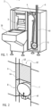
- closure elements generally have a generally flattened tubular shape, as visible in the figure 2 .
- stopper elements 1 must be sorted, in order to supply a workstation (not shown), located downstream within a production line. Such sorting is carried out through a supply device 2.
- FIG. 1 An example of such a device 2 is shown in the figure 1 . It comprises a lifting means 3 for sorting said stopper elements 1 according to their orientation.
- said lifting means 3 may consist of a “waterfall”, comprising a sorting belt plunging into a hopper or bin 30, into which the plugging elements 1 are previously poured in bulk.
- the plugging elements 1 are expelled from the lifting means 3, in particular by successive trains, in a discontinuous manner. They can pass through a transfer zone 4, provided with at least one single-line column 40, extending vertically or substantially vertically, within which the stopper elements 1 accumulate by stacking, ensuring a buffer stock, so as to allow a continuous supply.
- the device 2 Downstream of said lifting means 3, the device 2 comprises a means 5 for referencing the unit of said stopper elements 1 in a regular flow. In other words, a step is created between the successive products.
- Such a referencing means 5 may comprise a referencing wheel, provided to rotate. Generally, it comprises peripheral housings, within which the accumulated plugging elements 1 are successively inserted one by one, as said wheel rotates, in particular from the lower end of the column 40. During their passage within this referencing wheel, the plugging elements 1 may then undergo additional sorting, in particular making it possible to check their angular orientation according to a chosen angle.
- the device 2 comprises a conveyor 6, in particular an ascending conveyor for bringing the referenced elements 1, one by one, from the referencing means 5 to said workstation.
- Such a conveyor 6 may comprise a belt 60 equipped with branches 61, located at regular intervals, pushing the plugging elements 1, forming the regular flow along said conveyor 6.
- a conveyor 6 is ascending.
- This conveyor 6 may extend in all directions, preferably vertically or substantially vertically.
- the conveyor 6 may comprise a path 62, provided in a hollow, inside which the plugging elements 1 circulate.
- a path comprises a bottom 63, surrounded on either side by side walls 64.
- a recess may be provided within said bottom 63, through which the branches 61 pass.
- the invention provides a step of checking each of said closure elements 1.
- a check is intended to be visual, so as to verify the aspects of each closure element 1, such as its intrinsic characteristics, in particular shape and color, as well as its correct positioning, but also the presence of any foreign body.
- the device 2 comprises a vision means 7 for checking the conformity of said plugging elements 1 when they arrive at a control zone.
- Such a control zone may extend to the level of the referencing means 5 and/or the conveyor 6.
- the device 2 comprises, located downstream of said viewing means 7, a means for expelling non-compliant stopper elements 1.
- the expulsion means is located at the level of the conveyor 6, in the form of a mobile ejection member, controlled automatically and in a synchronized manner with the advancement of the regular flow of stopper elements 1.
- the invention provides for improving the visual inspection carried out on the plugging elements 1, in particular by increasing the contrast between said elements and their environment.
- the invention provides to be able to choose, depending on the verifiable characteristics of a type or format of stopper elements 1, the most suitable contrast depending on the inspection to be carried out.
- the most suitable contrast may be chosen preferentially depending on the limits or edges of the stopper elements 1 to be inspected, namely that the visual differentiation between the periphery of a stopper element 1 and the surrounding surfaces must be clear and precise.
- said control zone comprises at least two successive sections 8, 9 each comprising a distinct colour. It is then possible to choose which section 8 or 9 constitutes the most suitable contrast depending on the visual aspects to be controlled of the plugging element 1, then to carry out the control on this section 8 (or 9), rather than at the level of the other 9 (or reciprocally 8).
- sections 8,9 follow one another in relation to the direction of movement of the plugging elements 1, in a contiguous or adjacent manner as visible in the Figures 2 to 4 .
- sections 8,9 can be spaced, separated by an intermediate section without a specifically chosen or determined color.
- the control area comprises two sections 8,9, having different colours (represented by hatching). It is possible to have more than two sections 8,9, in particular a number of sections with as many different colours as the number of productions depending on the different characteristics of the capping elements 1 to be controlled.
- the colours of the sections 8,9 may be chosen and specifically determined, namely that at least one section, preferably each section 8,9, may have a deliberately modified colour, compared to the initial colours of the surrounding structure.
- This modification may come from a change of material for the structure of the environment, or by applying a covering, such as paint or a colored film.
- a covering such as paint or a colored film.
- the modification of the colors of at least one of the sections 8, 9 is carried out at the level of the conveyor 6, in particular of the path 62 of the conveyor 6, on the surfaces of the bottom 63 and/or of one and/or the other of the side walls 64.
- all the colors of the entire environment, in particular of the fixed structural elements, within a section 8, 9 are modified and unified according to a single and same color.
- the modification of the colors of the sections 8, 9 can be carried out at the level of the referencing means 5, on the surface of the referencing wheel and/or on the internal walls of the housings distributed regularly around the periphery of said wheel and each intended to receive a plugging element 1.
- the color matches the color of the rest of the device 1.
- the two sections 8,9 may be of complementary colors.
- the colors of two different sections 8,9 are clearly distinguishable, in particular to the naked eye, without risk of confusion. They may be opposite. Thus, they may for example be respectively green and red, or orange and blue or even black and white.
- one of the sections 8 may be white in color while the other of the sections 9 is black in color.
- the materials constituting the conveyor 6 are black and one of the sections 8 is entirely modified to white, the other section 9 then being constituted by the conveyor 6 in the initial color state.
- said vision means 7 may comprise at least one photographic apparatus, of the camera type or of the optical sensor type.
- the vision means 7 makes it possible to record one or more shots of each stopper element 1, or even to record a sequence, of the video type.
- Such a vision means 7 is intended to be digital.
- additional computer resources provide digital processing automatically, in particular by comparison with a reference image of a compliant stopper element 1.
- the device 2 comprises a means for moving the vision means 7, from a position facing one of said sections 8 (or 9) to a position facing the other of said sections 9 (or respectively 8), and vice versa.
- the vision means 7 it is possible to choose the positioning of the vision means 7, to carry out the visual capture and the check facing the section 8, 9 with the best contrast.
- said movement means can be provided manually, namely that it is physically moved by an operator through an intervention directly on the device 2.
- said movement means is provided to be automatic.
- an operator determines the section 8,9 with the best contrast and controls the movement of the vision means 7 which then positions itself opposite said chosen section 8,9.
- section 8.9 with the best contrast can be recorded for a given production of plugging elements 1 and, at the time of launching said production, the moving means automatically brings, without additional intervention, the vision means 7 opposite the section 8,9 previously recorded for this production, according to said plugging elements 1 to be checked.
- the section 8,9 with the best contrast can be determined automatically by the device 2, through a recognition of the color of the closure elements 1, in particular by a suitable sensor, then a digital comparison with the sections 8,9 in order to obtain the best possible contrast. It is also possible for the device 2 to directly interpret data relating to the recipe, known and recorded, in order to choose the section 8,9 with the best contrast.
- the vision means 7 is provided fixed. It can comprise at least a first capture beam 70 oriented towards one of said sections 8, 9 and a second capture beam 70 oriented towards the other of said sections 9 (or respectively 8).
- the vision means 7 is fixed but can comprise a wide capture beam 70, making it possible to cover at least two sections 8, 9. A blocking element 1 is then checked as it passes over each section 8, 9, in particular the one offering a better contrast. Several captures can be made and compared, in order to automatically determine the one which presents the best contrast with each blocking element 1.
- a vision means 7 can be located opposite the sections 8,9, namely frontally with respect to the conveyor 6 or by means of reference 5, in particular parallel or substantially parallel to the bottom 63.
- a vision means 7 can be positioned on one of the sides of the sections 8, 9, namely laterally relative to the conveyor 6 or to the referencing means 5. Consequently, at least one portion 65 of a side wall 64 of the path 62 of said conveyor 6 can comprise an opening or is made of a translucent material, allowing visual capture by said vision means 7. It is thus possible to transversely control the closure elements 1, on their edge, in particular to check the integrity of the tamper-evident ring.
- the vision means 7 can be positioned to the side relative to the referencing means 5, placed on the periphery and oriented radially towards the inside of the housings intended to receive the plugging elements 1, thus making it possible to control them laterally on their edge.
- the invention also relates to a method for supplying sorted plugging elements 1 to supply the downstream workstation.
- such a supply method is dedicated to the implementation of the supply device 2 according to the invention.
- the plugging elements 1 are sorted according to their orientation within the lifting means 3. Then, the sorted plugging elements 1 are referenced to the unit, to convey them one by one in a regular flow to the work station via the conveyor 6.
- a visual inspection of the plugging elements 1 is carried out with a vision means 7 during their referencing and/or their routing to the downstream workstation at the level of the inspection zone.
- blockage 1 detected presenting or likely to present an anomaly.
- control zone comprises at least two successive sections 8,9, each with a distinct colour.
- the visual inspection step is carried out at a chosen section 8 or 9 whose color ensures better contrast with the plugging elements 1 to be inspected.
- the improvement of the contrast may be provided to combine the improvement of the contrast through the choice of the control at the level of one of the sections 8,9, with a configurable fluctuation of the light intensity.
- it is possible to modify the brightness depending on the color of the section 8,9 chosen for the control and also on the characteristics of the plugging elements 1, such as their color but also their material.
- the visual capture is improved, with in particular a shorter exposure time, ensuring a control in a reduced period of time, making it possible to increase the speed of movement of the plugging elements 1, and thus the production rate of the supply device 2.
Landscapes
- Engineering & Computer Science (AREA)
- Mechanical Engineering (AREA)
- Immunology (AREA)
- Pathology (AREA)
- Analytical Chemistry (AREA)
- Biochemistry (AREA)
- General Health & Medical Sciences (AREA)
- General Physics & Mathematics (AREA)
- Physics & Mathematics (AREA)
- Chemical & Material Sciences (AREA)
- Life Sciences & Earth Sciences (AREA)
- Health & Medical Sciences (AREA)
- Sorting Of Articles (AREA)
- Sealing Of Jars (AREA)
- Discharge Of Articles From Conveyors (AREA)
- Branching, Merging, And Special Transfer Between Conveyors (AREA)
Claims (14)
- Vorrichtung (2) zum Bereitstellen von sortierten Verschlusselementen (1), um eine nachgeschaltete Arbeitsstation zu versorgen, wobei die Vorrichtung Folgendes aufweist:- ein Hebemittel (3), um eine Sortierung der Elemente (1) nach ihrer Ausrichtung durchzuführen;- dem Hebemittel (3) nachgeschaltet ein Mittel (5) zur Einzelreferenzierung der Verschlusselemente (1) in einem gleichmäßigen Fluss:- am Ausgang des Referenzierungsmittels (5) einen Förderer (6), um die referenzierten Elemente (1) einzeln zu der Arbeitsstation zu transportieren;- ein Sichtmittel (7), um die Konformität der Elemente (1) zu überprüfen, wenn sie in einem Prüfbereich der Vorrichtung (2) ankommen, wobei sich der Prüfbereich am Referenzierungsmittel (5) und/oder am Förderer (6) erstreckt;- dem Sichtmittel (7) nachgeschaltet ein Mittel zum Auswerfen der nicht konformen Elemente (1); dadurch gekennzeichnet, dass mindestens:- der Prüfbereich mindestens zwei aufeinanderfolgende Abschnitte (8, 9) mit jeweils einer eigenen Farbe aufweist.
- Vorrichtung (2) zum Bereitstellen nach Anspruch 1, dadurch gekennzeichnet, dass sie ein Mittel zum Bewegen des Sichtmittels (7) von einer Position gegenüber dem einen der Abschnitte (8) zu einer Position gegenüber dem anderen der Abschnitte (9) und umgekehrt aufweist.
- Vorrichtung (2) zum Bereitstellen nach Anspruch 2, dadurch gekennzeichnet, dass das Mittel zum Bewegen manuell vorgesehen ist.
- Vorrichtung (2) zum Bereitstellen nach Anspruch 2, dadurch gekennzeichnet, dass das Mittel zum Bewegen automatisch vorgesehen ist.
- Vorrichtung (2) zum Bereitstellen nach Anspruch 1, dadurch gekennzeichnet, dass das Sichtmittel (7) feststehend ist und einen breiten Erfassungsstrahl (70) aufweist, der auf die Abschnitte (8, 9) gerichtet ist.
- Vorrichtung (2) zum Bereitstellen nach Anspruch 1, dadurch gekennzeichnet, dass das Sichtmittel (7) feststehend ist und mindestens Folgendes aufweist:- einen ersten Erfassungsstrahl (70), der auf einen der Abschnitte (8) gerichtet ist;- einen zweiten Erfassungsstrahl (70), der auf einen anderen der Abschnitte (9) gerichtet ist.
- Vorrichtung (2) zum Bereitstellen nach einem der vorhergehenden Ansprüche, dadurch gekennzeichnet, dass zwei Abschnitte (8, 9) komplementäre Farben haben.
- Vorrichtung (2) zum Bereitstellen nach Anspruch 7, dadurch gekennzeichnet, dass einer der Abschnitte (8) eine weiße Farbe hat, während der andere der Abschnitte (9) eine schwarze Farbe hat.
- Verfahren zum Bereitstellen von sortierten Verschlusselementen (1), um eine nachgeschaltete Arbeitsstation zu versorgen, das mindestens die folgenden Schritte aufweist:- Sortieren der Elemente (1) nach ihrer Ausrichtung innerhalb eines Hebemittels (3);- Einzelreferenzieren der sortierten Elemente (1) und anschließendes einzelnes Transportieren zur Arbeitsstation in einem gleichmäßigen Fluss über einen Förderer (6);- Durchführen einer visuellen Prüfung der Elemente (1) mit einem Sichtmittel (7) in einem Prüfbereich während ihrer Referenzierung und/oder ihres Transports zur nachgeschalteten Arbeitsstation; und- Steuern des Auswerfens der Elemente (1), die bei der visuellen Prüfung als nicht konform erkannt wurden; dadurch gekennzeichnet, dass:- der Prüfbereich mindestens zwei aufeinanderfolgende Abschnitte (8, 9) mit jeweils einer eigenen Farbe aufweist;- der Schritt der visuellen Prüfung in einem ausgewählten Abschnitt (8, 9) durchgeführt wird, dessen Farbe einen besseren Kontrast zu den zu prüfenden Elementen (1) gewährleistet.
- Verfahren zum Bereitstellen nach Anspruch 9, dadurch gekennzeichnet, dass das Sichtmittel (7) feststehend ist und einen breiten Erfassungsstrahl (70) aufweist, der auf die Abschnitte (8, 9) gerichtet ist.
- Verfahren zum Bereitstellen nach Anspruch 9, dadurch gekennzeichnet, dass das Sichtmittel (7) feststehend ist und mindestens einen ersten Erfassungsstrahl (70) aufweist, der auf einen der Abschnitte (8) gerichtet ist, und einen zweiten Erfassungsstrahl (70), der auf den anderen der Abschnitte (9) gerichtet ist, und dadurch, dass der erste Strahl (70) oder der zweite Strahl (70) in Abhängigkeit von dem gewählten Abschnitt (8, 9) ausgewählt wird.
- Verfahren zum Bereitstellen nach Anspruch 9, dadurch gekennzeichnet, dass das Sichtmittel (7) beweglich ist und das Sichtmittel gegenüber dem ausgewählten Abschnitt (8, 9) bewegt wird.
- Verfahren zum Bereitstellen nach Anspruch 12, dadurch gekennzeichnet, dass das Sichtmittel (7) manuell bewegt wird.
- Verfahren zum Bereitstellen nach Anspruch 10, dadurch gekennzeichnet, dass das Sichtmittel (7) automatisch bewegt wird.
Applications Claiming Priority (2)
| Application Number | Priority Date | Filing Date | Title |
|---|---|---|---|
| FR1858927A FR3086652B1 (fr) | 2018-09-28 | 2018-09-28 | Dispositif et procede de fourniture d'elements de bouchage tries |
| PCT/EP2019/076141 WO2020064986A1 (fr) | 2018-09-28 | 2019-09-27 | Dispositif et procede de fourniture d'elements de bouchage tries |
Publications (2)
| Publication Number | Publication Date |
|---|---|
| EP3856675A1 EP3856675A1 (de) | 2021-08-04 |
| EP3856675B1 true EP3856675B1 (de) | 2024-11-27 |
Family
ID=67956807
Family Applications (1)
| Application Number | Title | Priority Date | Filing Date |
|---|---|---|---|
| EP19773444.5A Active EP3856675B1 (de) | 2018-09-28 | 2019-09-27 | Vorrichtung und verfahren zum bereitstellen von sortierten stopfenelementen |
Country Status (7)
| Country | Link |
|---|---|
| US (1) | US11498820B2 (de) |
| EP (1) | EP3856675B1 (de) |
| CN (1) | CN112770998B (de) |
| CA (1) | CA3111856A1 (de) |
| FR (1) | FR3086652B1 (de) |
| MX (1) | MX2021003665A (de) |
| WO (1) | WO2020064986A1 (de) |
Families Citing this family (2)
| Publication number | Priority date | Publication date | Assignee | Title |
|---|---|---|---|---|
| CN111689006A (zh) * | 2020-06-03 | 2020-09-22 | 合肥安杰特光电科技有限公司 | 包装机的计数装置 |
| EP4596464A1 (de) * | 2024-01-31 | 2025-08-06 | Inpeco SA | Vorrichtung zum rekrutieren und laden von kappen für behälter biologischer proben |
Family Cites Families (17)
| Publication number | Priority date | Publication date | Assignee | Title |
|---|---|---|---|---|
| JP3335517B2 (ja) * | 1995-12-25 | 2002-10-21 | ワイケイケイ株式会社 | 物品整送装置 |
| FR2874424B1 (fr) * | 2004-08-17 | 2007-05-11 | Materiel Arboriculture | Dispositif d'analyse optique de produits tels que des fruits a eclairage indirect |
| FR2876990B1 (fr) * | 2004-10-25 | 2007-01-12 | Sidel Sas | Perfectionnement aux machines d'appret utilisees pour orienter des objets en vue de l'alimentation d'une chaine de preparation de produits comportant lesdits objets |
| DE102007018870A1 (de) * | 2007-04-19 | 2008-10-23 | Krones Ag | Inspektionsvorrichtung zum Untersuchen von Behältnisverschlüssen |
| DE102009041212A1 (de) * | 2009-09-11 | 2011-04-07 | Krones Ag | Vorrichtung und Verfahren zum Kontrollieren von Gefäßverschlüssen |
| FR2961797B1 (fr) * | 2010-06-29 | 2013-03-29 | Sidel Participations | Procede et machine de preparation d'objets du genre bouchons, capsules ou autres |
| DE102010032410B4 (de) * | 2010-07-27 | 2014-11-13 | Mall + Herlan Schweiz Ag | Inspektionsvorrichtung, Fertigungsanlage mit Inspektionsvorrichtung und Inspektionsverfahren für Gefäße |
| DE102012216163B4 (de) * | 2012-01-11 | 2017-03-09 | Robert Bosch Gmbh | Vorrichtung zum Zuführen von Kappen mit Überwachungssystem |
| DE102014100699A1 (de) * | 2014-01-22 | 2015-07-23 | Krones Ag | Vorrichtung zur optischen Inspektion von Verpackungsgegenständen in der Getränketechnologie |
| US9352361B2 (en) * | 2014-05-05 | 2016-05-31 | Arol S.P.A. | Elevator for caps |
| CA2971367C (fr) * | 2014-12-30 | 2023-01-17 | Gebo Packaging Solutions France | Dispositif et methode de fourniture fiable d'elements de bouchage conformes |
| WO2016107655A1 (fr) * | 2014-12-30 | 2016-07-07 | Gebo Packaging Solutions France | Dispositif et méthode de fourniture d'éléments orientés |
| FR3035088B1 (fr) * | 2015-04-16 | 2019-05-17 | Sidel Participations | "procede d'alignement et de redressement de preformes par centrifugation et dispositif associe" |
| MX395688B (es) * | 2015-07-31 | 2025-03-25 | Gebo Packaging Solutions France | Suministro de tapas de referencia. |
| FR3063717B1 (fr) * | 2017-03-08 | 2021-07-23 | Gebo Packaging Solutions France | Dispositif et methode de fourniture fiable d'elements de bouchage conformes |
| CN109704003B (zh) * | 2017-10-25 | 2021-11-02 | 泰科电子(上海)有限公司 | 供料系统 |
| WO2019082112A1 (en) * | 2017-10-27 | 2019-05-02 | Ronchi Mario S.P.A. | APPARATUS FOR ALIGNING RANDOMIZED CONTAINERS COMPRISING INDEPENDENT EXTRACTION MEANS EACH OF OTHERS |
-
2018
- 2018-09-28 FR FR1858927A patent/FR3086652B1/fr active Active
-
2019
- 2019-09-27 MX MX2021003665A patent/MX2021003665A/es unknown
- 2019-09-27 US US17/280,862 patent/US11498820B2/en active Active
- 2019-09-27 EP EP19773444.5A patent/EP3856675B1/de active Active
- 2019-09-27 CN CN201980063984.9A patent/CN112770998B/zh active Active
- 2019-09-27 CA CA3111856A patent/CA3111856A1/fr active Pending
- 2019-09-27 WO PCT/EP2019/076141 patent/WO2020064986A1/fr not_active Ceased
Also Published As
| Publication number | Publication date |
|---|---|
| CN112770998B (zh) | 2023-09-19 |
| EP3856675A1 (de) | 2021-08-04 |
| MX2021003665A (es) | 2021-05-28 |
| WO2020064986A1 (fr) | 2020-04-02 |
| BR112021005810A2 (pt) | 2021-06-29 |
| FR3086652B1 (fr) | 2020-10-23 |
| US11498820B2 (en) | 2022-11-15 |
| CA3111856A1 (fr) | 2020-04-02 |
| FR3086652A1 (fr) | 2020-04-03 |
| CN112770998A (zh) | 2021-05-07 |
| US20220002129A1 (en) | 2022-01-06 |
Similar Documents
| Publication | Publication Date | Title |
|---|---|---|
| US6937339B2 (en) | Inspection device and system for inspecting foreign matters in a liquid filled transparent container | |
| CN107076680B (zh) | 用于对容器进行透射光检查的检查设备和方法 | |
| EP3233460B1 (de) | Vorrichtung und verfahren zur qualitätsüberprüfung von faltschachteln und produktionsanlage mit solch einer qualitätskontrollvorrichtung | |
| FR2585131A1 (fr) | Controle des goulots de recipient | |
| EP3443330B1 (de) | Verfahren und system zur überprüfung einer vorrichtung zur optischen inspektion von behältern aus glas | |
| WO2020064986A1 (fr) | Dispositif et procede de fourniture d'elements de bouchage tries | |
| CN102941189A (zh) | 水果分选机可控旋转角度齿纹托盘装置 | |
| CN103203324A (zh) | 带有监控系统的用于输送盖的设备 | |
| FR2890447A1 (fr) | Procede et installation pour detecter des corps etrangers a l'interieur d'un recipient | |
| EP3372539B1 (de) | Vorrichtung und methode der zuverlässigen versorgung mit konformen verschlusselementen | |
| HK1213231A1 (zh) | 用於帽盖的升降机 | |
| JP3963871B2 (ja) | 王冠打栓不良検査装置 | |
| JP2009119410A (ja) | 粒状物等の光学判別装置及び粒状物等の光学式選別装置 | |
| EP3206805B1 (de) | Verfahren, vorrichtung und inspektionslinie zur optischen auslesung relief an einer seitenwand eines behälters | |
| JP2002310629A (ja) | 周面撮像装置及び周面検査装置 | |
| FR3086653A1 (fr) | Dispositif et procede de fourniture d'elements de bouchage | |
| WO2001055705A1 (fr) | Installation et procede pour la detection de glacures | |
| KR102143216B1 (ko) | 부품공급 및 선별장치, 그리고 이를 이용한 부품선별방법 | |
| BR112021005810B1 (pt) | Dispositivo e método para fornecer elementos de parada classificados | |
| WO2017129915A1 (fr) | Installation de redressage automatisé d'une mèche de bougie et procédé de redressage automatisé associé | |
| JP7208462B2 (ja) | 容器方向判定装置および容器搬送装置 | |
| CA3141260A1 (fr) | Dispositif de fourniture d'elements de bouchage tries | |
| FR3157935A1 (fr) | Procédé de contrôle d’une installation de fabrication de récipients en verre en secteur chaud par obtention d’une image | |
| EP4643118A1 (de) | Verfahren zur kontaktlosen in-line-inspektion von behältern und station zur durchführung des verfahrens | |
| WO2021009196A1 (fr) | Doigt d'ejection pour dispositif de fourniture d'elements de bouchage tries et procede de fabrication par moulage |
Legal Events
| Date | Code | Title | Description |
|---|---|---|---|
| STAA | Information on the status of an ep patent application or granted ep patent |
Free format text: STATUS: UNKNOWN |
|
| STAA | Information on the status of an ep patent application or granted ep patent |
Free format text: STATUS: THE INTERNATIONAL PUBLICATION HAS BEEN MADE |
|
| PUAI | Public reference made under article 153(3) epc to a published international application that has entered the european phase |
Free format text: ORIGINAL CODE: 0009012 |
|
| STAA | Information on the status of an ep patent application or granted ep patent |
Free format text: STATUS: REQUEST FOR EXAMINATION WAS MADE |
|
| 17P | Request for examination filed |
Effective date: 20210420 |
|
| AK | Designated contracting states |
Kind code of ref document: A1 Designated state(s): AL AT BE BG CH CY CZ DE DK EE ES FI FR GB GR HR HU IE IS IT LI LT LU LV MC MK MT NL NO PL PT RO RS SE SI SK SM TR |
|
| DAV | Request for validation of the european patent (deleted) | ||
| DAX | Request for extension of the european patent (deleted) | ||
| GRAP | Despatch of communication of intention to grant a patent |
Free format text: ORIGINAL CODE: EPIDOSNIGR1 |
|
| STAA | Information on the status of an ep patent application or granted ep patent |
Free format text: STATUS: GRANT OF PATENT IS INTENDED |
|
| INTG | Intention to grant announced |
Effective date: 20240619 |
|
| RIN1 | Information on inventor provided before grant (corrected) |
Inventor name: SCHMITT, ARNAUD Inventor name: SPIESSER, DANIEL Inventor name: ROTH, EMMANUEL |
|
| GRAS | Grant fee paid |
Free format text: ORIGINAL CODE: EPIDOSNIGR3 |
|
| GRAA | (expected) grant |
Free format text: ORIGINAL CODE: 0009210 |
|
| STAA | Information on the status of an ep patent application or granted ep patent |
Free format text: STATUS: THE PATENT HAS BEEN GRANTED |
|
| AK | Designated contracting states |
Kind code of ref document: B1 Designated state(s): AL AT BE BG CH CY CZ DE DK EE ES FI FR GB GR HR HU IE IS IT LI LT LU LV MC MK MT NL NO PL PT RO RS SE SI SK SM TR |
|
| RAP1 | Party data changed (applicant data changed or rights of an application transferred) |
Owner name: SIDEL PARTICIPATIONS |
|
| REG | Reference to a national code |
Ref country code: GB Ref legal event code: FG4D Free format text: NOT ENGLISH |
|
| REG | Reference to a national code |
Ref country code: CH Ref legal event code: EP |
|
| P01 | Opt-out of the competence of the unified patent court (upc) registered |
Free format text: CASE NUMBER: APP_60881/2024 Effective date: 20241113 |
|
| REG | Reference to a national code |
Ref country code: IE Ref legal event code: FG4D Free format text: LANGUAGE OF EP DOCUMENT: FRENCH |
|
| REG | Reference to a national code |
Ref country code: DE Ref legal event code: R096 Ref document number: 602019062614 Country of ref document: DE |
|
| REG | Reference to a national code |
Ref country code: SE Ref legal event code: TRGR |
|
| REG | Reference to a national code |
Ref country code: LT Ref legal event code: MG9D |
|
| REG | Reference to a national code |
Ref country code: NL Ref legal event code: MP Effective date: 20241127 |
|
| PG25 | Lapsed in a contracting state [announced via postgrant information from national office to epo] |
Ref country code: PT Free format text: LAPSE BECAUSE OF FAILURE TO SUBMIT A TRANSLATION OF THE DESCRIPTION OR TO PAY THE FEE WITHIN THE PRESCRIBED TIME-LIMIT Effective date: 20250327 Ref country code: IS Free format text: LAPSE BECAUSE OF FAILURE TO SUBMIT A TRANSLATION OF THE DESCRIPTION OR TO PAY THE FEE WITHIN THE PRESCRIBED TIME-LIMIT Effective date: 20250327 Ref country code: HR Free format text: LAPSE BECAUSE OF FAILURE TO SUBMIT A TRANSLATION OF THE DESCRIPTION OR TO PAY THE FEE WITHIN THE PRESCRIBED TIME-LIMIT Effective date: 20241127 |
|
| PG25 | Lapsed in a contracting state [announced via postgrant information from national office to epo] |
Ref country code: FI Free format text: LAPSE BECAUSE OF FAILURE TO SUBMIT A TRANSLATION OF THE DESCRIPTION OR TO PAY THE FEE WITHIN THE PRESCRIBED TIME-LIMIT Effective date: 20241127 Ref country code: NL Free format text: LAPSE BECAUSE OF FAILURE TO SUBMIT A TRANSLATION OF THE DESCRIPTION OR TO PAY THE FEE WITHIN THE PRESCRIBED TIME-LIMIT Effective date: 20241127 |
|
| PG25 | Lapsed in a contracting state [announced via postgrant information from national office to epo] |
Ref country code: BG Free format text: LAPSE BECAUSE OF FAILURE TO SUBMIT A TRANSLATION OF THE DESCRIPTION OR TO PAY THE FEE WITHIN THE PRESCRIBED TIME-LIMIT Effective date: 20241127 |
|
| PG25 | Lapsed in a contracting state [announced via postgrant information from national office to epo] |
Ref country code: ES Free format text: LAPSE BECAUSE OF FAILURE TO SUBMIT A TRANSLATION OF THE DESCRIPTION OR TO PAY THE FEE WITHIN THE PRESCRIBED TIME-LIMIT Effective date: 20241127 |
|
| PG25 | Lapsed in a contracting state [announced via postgrant information from national office to epo] |
Ref country code: NO Free format text: LAPSE BECAUSE OF FAILURE TO SUBMIT A TRANSLATION OF THE DESCRIPTION OR TO PAY THE FEE WITHIN THE PRESCRIBED TIME-LIMIT Effective date: 20250227 |
|
| PG25 | Lapsed in a contracting state [announced via postgrant information from national office to epo] |
Ref country code: GR Free format text: LAPSE BECAUSE OF FAILURE TO SUBMIT A TRANSLATION OF THE DESCRIPTION OR TO PAY THE FEE WITHIN THE PRESCRIBED TIME-LIMIT Effective date: 20250228 Ref country code: LV Free format text: LAPSE BECAUSE OF FAILURE TO SUBMIT A TRANSLATION OF THE DESCRIPTION OR TO PAY THE FEE WITHIN THE PRESCRIBED TIME-LIMIT Effective date: 20241127 |
|
| PG25 | Lapsed in a contracting state [announced via postgrant information from national office to epo] |
Ref country code: PL Free format text: LAPSE BECAUSE OF FAILURE TO SUBMIT A TRANSLATION OF THE DESCRIPTION OR TO PAY THE FEE WITHIN THE PRESCRIBED TIME-LIMIT Effective date: 20241127 |
|
| PG25 | Lapsed in a contracting state [announced via postgrant information from national office to epo] |
Ref country code: RS Free format text: LAPSE BECAUSE OF FAILURE TO SUBMIT A TRANSLATION OF THE DESCRIPTION OR TO PAY THE FEE WITHIN THE PRESCRIBED TIME-LIMIT Effective date: 20250227 |
|
| PG25 | Lapsed in a contracting state [announced via postgrant information from national office to epo] |
Ref country code: SM Free format text: LAPSE BECAUSE OF FAILURE TO SUBMIT A TRANSLATION OF THE DESCRIPTION OR TO PAY THE FEE WITHIN THE PRESCRIBED TIME-LIMIT Effective date: 20241127 |
|
| PG25 | Lapsed in a contracting state [announced via postgrant information from national office to epo] |
Ref country code: DK Free format text: LAPSE BECAUSE OF FAILURE TO SUBMIT A TRANSLATION OF THE DESCRIPTION OR TO PAY THE FEE WITHIN THE PRESCRIBED TIME-LIMIT Effective date: 20241127 |
|
| PG25 | Lapsed in a contracting state [announced via postgrant information from national office to epo] |
Ref country code: EE Free format text: LAPSE BECAUSE OF FAILURE TO SUBMIT A TRANSLATION OF THE DESCRIPTION OR TO PAY THE FEE WITHIN THE PRESCRIBED TIME-LIMIT Effective date: 20241127 |
|
| PG25 | Lapsed in a contracting state [announced via postgrant information from national office to epo] |
Ref country code: RO Free format text: LAPSE BECAUSE OF FAILURE TO SUBMIT A TRANSLATION OF THE DESCRIPTION OR TO PAY THE FEE WITHIN THE PRESCRIBED TIME-LIMIT Effective date: 20241127 |
|
| PG25 | Lapsed in a contracting state [announced via postgrant information from national office to epo] |
Ref country code: SK Free format text: LAPSE BECAUSE OF FAILURE TO SUBMIT A TRANSLATION OF THE DESCRIPTION OR TO PAY THE FEE WITHIN THE PRESCRIBED TIME-LIMIT Effective date: 20241127 |
|
| PG25 | Lapsed in a contracting state [announced via postgrant information from national office to epo] |
Ref country code: CZ Free format text: LAPSE BECAUSE OF FAILURE TO SUBMIT A TRANSLATION OF THE DESCRIPTION OR TO PAY THE FEE WITHIN THE PRESCRIBED TIME-LIMIT Effective date: 20241127 |
|
| REG | Reference to a national code |
Ref country code: DE Ref legal event code: R097 Ref document number: 602019062614 Country of ref document: DE |
|
| PLBE | No opposition filed within time limit |
Free format text: ORIGINAL CODE: 0009261 |
|
| STAA | Information on the status of an ep patent application or granted ep patent |
Free format text: STATUS: NO OPPOSITION FILED WITHIN TIME LIMIT |
|
| REG | Reference to a national code |
Ref country code: CH Ref legal event code: L10 Free format text: ST27 STATUS EVENT CODE: U-0-0-L10-L00 (AS PROVIDED BY THE NATIONAL OFFICE) Effective date: 20251008 |
|
| PGFP | Annual fee paid to national office [announced via postgrant information from national office to epo] |
Ref country code: DE Payment date: 20250820 Year of fee payment: 7 |
|
| PGFP | Annual fee paid to national office [announced via postgrant information from national office to epo] |
Ref country code: IT Payment date: 20250820 Year of fee payment: 7 |
|
| PGFP | Annual fee paid to national office [announced via postgrant information from national office to epo] |
Ref country code: FR Payment date: 20250820 Year of fee payment: 7 Ref country code: AT Payment date: 20250822 Year of fee payment: 7 |
|
| PGFP | Annual fee paid to national office [announced via postgrant information from national office to epo] |
Ref country code: SE Payment date: 20250820 Year of fee payment: 7 |
|
| 26N | No opposition filed |
Effective date: 20250828 |
|
| REG | Reference to a national code |
Ref country code: AT Ref legal event code: UEP Ref document number: 1745556 Country of ref document: AT Kind code of ref document: T Effective date: 20241127 |
|
| REG | Reference to a national code |
Ref country code: CH Ref legal event code: H13 Free format text: ST27 STATUS EVENT CODE: U-0-0-H10-H13 (AS PROVIDED BY THE NATIONAL OFFICE) Effective date: 20260425 |