EP3371659B1 - Kontaktabhängiges metronom - Google Patents
Kontaktabhängiges metronom Download PDFInfo
- Publication number
- EP3371659B1 EP3371659B1 EP16862889.9A EP16862889A EP3371659B1 EP 3371659 B1 EP3371659 B1 EP 3371659B1 EP 16862889 A EP16862889 A EP 16862889A EP 3371659 B1 EP3371659 B1 EP 3371659B1
- Authority
- EP
- European Patent Office
- Prior art keywords
- metronome
- tempo
- controller
- sensor
- strikes
- Prior art date
- Legal status (The legal status is an assumption and is not a legal conclusion. Google has not performed a legal analysis and makes no representation as to the accuracy of the status listed.)
- Active
Links
Images


Classifications
-
- G—PHYSICS
- G04—HOROLOGY
- G04F—TIME-INTERVAL MEASURING
- G04F5/00—Apparatus for producing preselected time intervals for use as timing standards
- G04F5/02—Metronomes
- G04F5/025—Electronic metronomes
-
- G—PHYSICS
- G10—MUSICAL INSTRUMENTS; ACOUSTICS
- G10H—ELECTROPHONIC MUSICAL INSTRUMENTS; INSTRUMENTS IN WHICH THE TONES ARE GENERATED BY ELECTROMECHANICAL MEANS OR ELECTRONIC GENERATORS, OR IN WHICH THE TONES ARE SYNTHESISED FROM A DATA STORE
- G10H1/00—Details of electrophonic musical instruments
- G10H1/36—Accompaniment arrangements
- G10H1/40—Rhythm
-
- G—PHYSICS
- G10—MUSICAL INSTRUMENTS; ACOUSTICS
- G10H—ELECTROPHONIC MUSICAL INSTRUMENTS; INSTRUMENTS IN WHICH THE TONES ARE GENERATED BY ELECTROMECHANICAL MEANS OR ELECTRONIC GENERATORS, OR IN WHICH THE TONES ARE SYNTHESISED FROM A DATA STORE
- G10H1/00—Details of electrophonic musical instruments
- G10H1/46—Volume control
-
- G—PHYSICS
- G10—MUSICAL INSTRUMENTS; ACOUSTICS
- G10H—ELECTROPHONIC MUSICAL INSTRUMENTS; INSTRUMENTS IN WHICH THE TONES ARE GENERATED BY ELECTROMECHANICAL MEANS OR ELECTRONIC GENERATORS, OR IN WHICH THE TONES ARE SYNTHESISED FROM A DATA STORE
- G10H3/00—Instruments in which the tones are generated by electromechanical means
- G10H3/12—Instruments in which the tones are generated by electromechanical means using mechanical resonant generators, e.g. strings or percussive instruments, the tones of which are picked up by electromechanical transducers, the electrical signals being further manipulated or amplified and subsequently converted to sound by a loudspeaker or equivalent instrument
- G10H3/14—Instruments in which the tones are generated by electromechanical means using mechanical resonant generators, e.g. strings or percussive instruments, the tones of which are picked up by electromechanical transducers, the electrical signals being further manipulated or amplified and subsequently converted to sound by a loudspeaker or equivalent instrument using mechanically actuated vibrators with pick-up means
- G10H3/146—Instruments in which the tones are generated by electromechanical means using mechanical resonant generators, e.g. strings or percussive instruments, the tones of which are picked up by electromechanical transducers, the electrical signals being further manipulated or amplified and subsequently converted to sound by a loudspeaker or equivalent instrument using mechanically actuated vibrators with pick-up means using a membrane, e.g. a drum; Pick-up means for vibrating surfaces, e.g. housing of an instrument
-
- G—PHYSICS
- G10—MUSICAL INSTRUMENTS; ACOUSTICS
- G10H—ELECTROPHONIC MUSICAL INSTRUMENTS; INSTRUMENTS IN WHICH THE TONES ARE GENERATED BY ELECTROMECHANICAL MEANS OR ELECTRONIC GENERATORS, OR IN WHICH THE TONES ARE SYNTHESISED FROM A DATA STORE
- G10H2210/00—Aspects or methods of musical processing having intrinsic musical character, i.e. involving musical theory or musical parameters or relying on musical knowledge, as applied in electrophonic musical tools or instruments
- G10H2210/031—Musical analysis, i.e. isolation, extraction or identification of musical elements or musical parameters from a raw acoustic signal or from an encoded audio signal
- G10H2210/076—Musical analysis, i.e. isolation, extraction or identification of musical elements or musical parameters from a raw acoustic signal or from an encoded audio signal for extraction of timing, tempo; Beat detection
-
- G—PHYSICS
- G10—MUSICAL INSTRUMENTS; ACOUSTICS
- G10H—ELECTROPHONIC MUSICAL INSTRUMENTS; INSTRUMENTS IN WHICH THE TONES ARE GENERATED BY ELECTROMECHANICAL MEANS OR ELECTRONIC GENERATORS, OR IN WHICH THE TONES ARE SYNTHESISED FROM A DATA STORE
- G10H2220/00—Input/output interfacing specifically adapted for electrophonic musical tools or instruments
- G10H2220/155—User input interfaces for electrophonic musical instruments
- G10H2220/185—Stick input, e.g. drumsticks with position or contact sensors
Definitions
- the present invention relates to a metronome.
- the invention disclosed herein regarding a device that produces regular, metrical ticks (e . g ., beats, clicks, visual) - settable in beats per time (e.g., minute). These ticks can represent a fixed, regular aural pulse or visual indicator.
- regular, metrical ticks e.g ., beats, clicks, visual
- ticks can represent a fixed, regular aural pulse or visual indicator.
- Such devices are regularly used by musicians to help them keep a tempo as they play.
- a device can be a metronome.
- the term “strike” or a derivative thereof is used synonymously with “impact,” “contact,” and “an applied force” when referring to striking the metronome.
- the term “event” or a derivative thereof can be defined as any type of input or action that can result in the adjustment of a characteristic of the metronome.
- metronome 100 can have one or more of the following components: a body 102 , an input device, such as a sensor 110 , an output device, such as a speaker 120 , a controller 130 , a tempo controller 150 , and a power source 172 . Additionally, the metronome 100 can have a processor, a memory, and a computer executable program code. These components can make communication between different parts or components of the metronome possible so that the metronome can perform the requested function.
- the body 102 can be in any shape, form, or size.
- it can be in a shape of a visible pendulum, a cylinder, rectangular prism, cube, triangular prism, octagonal prism, triangular pyramid, square pyramid, cone, a sphere, a disc, or other shape.
- impact absorbing material are intended to encompass any energy absorbing materials that can be used to make an object resilient to impact and which through such use can reduce the likelihood of damage to the object when impacted by a second object.
- This definition encompasses, but is not limited to for example, a drum stick striking a portion of a metronome having an impact absorbing material.
- Such impact absorbing materials can be selected from materials that have at least one of the following properties: reversibly deforming, polymer, metal, plastic, amorphous pliable, impact absorbing, force absorbing, and/or cushioning absorbing materials.
- the body 102 of the metronome 100 can be made of any material, such as a polymeric, a non-polymeric composition, or a mixture of polymeric and non-polymeric material, a metal or a metal aggregate, wood, and/or stone.
- the body 102 can be made, in part or in whole, of an impact absorbing material to absorb the force of impact when the metronome 100 is struck, for example, by a drum stick.
- the body 102 of the metronome 100 can have an outer layer and an impact absorbing material 104 that can be positioned on or under the outer layer.
- the outer layer can be made, at least in part, of the impact absorbing material.
- the impact absorbing material 104 can be an inner impact absorbing material and can be secured to or configured in contact with and/or adhered to the interior surface of the body 102 or between the body 102 and an interior frame 106 (if any).
- the impact absorbing material 104 can be placed or configured in spaces between different components of the metronome 100 , as shown in Fig. 1 .
- the impact absorbing material 104 can be secured to or configured in contact with and/or adhered to the exterior of the metronome 100 , such as on the body 102 .
- the impact absorbing material 104 can be in a shape of a sleeve that can be placed or configured on the exterior of the metronome 100 , such that the impact absorbing material 104 can cover the entire length of the body 102 .
- the impact absorbing material 104 can be placed or configured on at least a portion of the exterior surface of the body 102 . For example, it can be placed such that it covers at least the edges of the body 102 .
- the impact absorbing material 104 can extend the entire length of the body 102 .
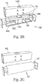
- the impact absorbing material 104 can overlap, cover, be in contact with and/or adhere to a portion of the interior of the body 102 , for example, the impact absorbing material 104 can be intermittently configured around and/or to at least, in part, surround the framework 106 , as shown in Fig. 2D .
- the impact absorbing material 104 can be one or more of a material such as rubber, neoprene, silicone, polymers, plastics, and other materials.
- the impact absorbing material can be made of or include silicon and can be in a shape of a sleeve.
- the body 102 and/or the framework 106 can be manufactured by a broad variety of methods.
- the body 102 and/or the framework 106 can be manufactured by casting, molding, forming, machining, and joining.
- Casting process can use processes such as centrifugal casting, continuous casting, die casting, evaporative pattern casting to name a few.
- Molding process can use one or more processes such as injection molding, compression molding, extrusion, blow molding, dip molding, and thermoforming to name a few.
- Forming process can use one or more of forging, rolling, extrusion, pressing, bending, and shearing to name a few.
- Machining process can use one or more of milling, turning, drilling, reaming, tapping sawing, shaping, and planning to name a few.
- Joining process can use one or more of welding, brazing, soldering, sintering, adhesive bonding, press fitting, and fastening to name a few.
- the body 102 and/or the framework 106 can also be manufactured by a 3D printing process.
- the body 102 is designed such that a portion or a side of the body 102 can be open or have an opening or an access to reveal at least a portion of a printed circuit board (PCB) 145 .
- the open side of the body 102 can also have at least one filler panel, such as a pair of filler panels 105 .
- the filler panels 105 can be configured and/or secured to any portion of the metronome 100 .
- each filler panel 105 can be configured and/or secured at each end of the metronome 100 .
- each filler panel 105 can cover at least a portion of the PCB 145 .
- Each of the filler panels 105 can be made of the same material as the body 102 or can be made of material different from the body 102 .
- the filler panels 105 can be made of any material, such as a polymeric, a non-polymeric composition, or a mixture of polymeric and non-polymeric material, a metal or a metal aggregate, wood, and/or stone. Similar to the body 102 , the filler panels 105 can be made of an impact absorbing material.
- each of the filler panels 105 can include a first material and an impact absorbing material 104 , which can be secured to or configured in the interior side of the first material of the filler panels 105 or can be secured or configured on the exterior of the filler panels 105 .
- each of the filler panels 105 can be such that each of the filler panels 105 can be inserted and be secured inside the metronome 100 .
- each of the filler panels 105 can be friction fitted at each end of the metronome 100 .
- the shape of each of the filler panels 105 can be in a shape of a disc, semi sphere, square, triangle, and rectangle. In an embodiment, as shown in Fig.
- each of the filler panels 105 can be in a shape of a rectangle having a length such that when inserted in to the open face of the body 102 , one end of each of the filler panels 105 is at each respective end of the metronome 100 and the other end of each of the filler panels 105 can come in contact to one another ( i.e. , the combination of the two filler panels 105 stretch the entire length of the metronome 100 ). In another embodiment, the combination of the length of each of the filler panels 105 is shorter than the entire length of the metronome 100 .
- the combination of the length of each of the filler panels 105 can cover at least one of three-quarters (3 ⁇ 4) of the entire length of the metronome 100 , two-thirds ( ) of the entire length of the metronome 100 , one-half (1 ⁇ 2) of the entire length of the metronome 100 , one-third (1 ⁇ 3) of the entire length of the metronome 100 , one-quarter (1 ⁇ 4) of the entire length of the metronome 100 , one-sixth (1/6) of the entire length of the metronome 100 , or one-eight (1 ⁇ 8) of the entire length of the metronome 100 , or less than one-eight (1 ⁇ 8) of the entire width of the metronome 100 , to name a few.
- Each of the rectangular shaped filler panels can have a width that is at least the same as the width of the metronome 100 or shorter.
- the width of each filler panel 105 can be at least one of three-quarter (3 ⁇ 4) of the entire width of the metronome 100 , two-thirds ( ) of the entire width of the metronome 100 , one-half (1 ⁇ 2) of the entire width of the metronome 100 , one-third (1 ⁇ 3) of the entire width of the metronome 100 , one-quarter (1 ⁇ 4) of the entire width of the metronome 100 , one-sixth (1/6) of the entire width of the metronome 100 , or one-eight (1 ⁇ 8) of the entire width of the metronome 100 , or less than one-eight (1 ⁇ 8) of the entire width of the metronome 100 , to name a few.
- the metronome 100 can have a width of from about 1 inch or less to about 3 inches or more, for example, 2 inches.
- the metronome 100 can have a height of from about 1 inch or less to about 3 inches or more, for example, 2 inches and a length of from about 5 inches or less to about 10 inches or more, such as a length of about 8.25 inches.
- the entire length of the metronome 100 can be from about 5.2 inches or less to about 11 inches or more, such as a length of about 9 inches.
- the chassis or framework 106 make the body 102 or at least a portion of the body 102 .
- the body 102 can be separate from the chassis or framework 106 .
- the body 102 can be placed over the chassis or framework 106.
- the framework 106 can include a support structure 108 to strengthen the framework 106 .
- the support structure 108 can include at least one rod-like structure 108A , such as at least two rod-like structures 108A and 108B , at least three rod-like structures 108A , 108B , and 108C , or at least four rod-like structures 108A , 108B , 108C , and 108D .
- the position of each of the rod-like structures 108A , 108B , 108C , and 108D with respect to one another can be such that they create a space sufficiently large enough to position and secure each of the components of the metronome 100.
- the rod-like structures 108A , 108B , 108C , and 108D can be designed to withstand a strike from a device or an instrument, such as a drum stick.
- the rod-like structures 108A , 108B , 108C , and 108D can withstand a force of from at least about 100 Newton (N) or less.
- N Newton
- the body 102 includes an inner surface that can have a set of ridges or rails 102A .
- the purpose of the ridges 102A is to strengthen the body 102 to better withstand the striking force of the musical instrument, such as a drum stick, striking the metronome 100 .
- the ridges 102A can create a rail-like structure to removably, but securely hold different components of the metronome 100 .
- each of the filler panels 105 can slide between the ridges 102A so that they can be removably configured and secured inside the metronome 100 .
- PCB printed circuit board
- any system and/or software disclosed can execute rule-based logic and/or other processing and/or other decision making by processing and/or using a single “criterion” or a plurality of criterion herein as "criteria”.
- a decision or processing step can be executed based on a single criterion and/or event
- the disclosure is intending to be broad and discloses a single criterion, at least one criterion, or criteria, or event.
- criteria plural
- a single criterion singular
- the application is not limited regarding the nature and/or type of computer executable software code and encompasses any and all code readable and executable by a computer and encompasses and equivalents and/or means, such as the terms "a computer executable program code means" and "a computer readable program code means” which are used herein synonymously and which are intended to encompass any time of software and/or program code and/or instructions readable and/or executable by a computing device and/or computer.
- All of the embodiments herein can be made, used, implemented and executed by computer readable program code means.
- the software products are not limited and can broadly be any software and or application product capable of processing the numerical methods and calculations disclosed herein.
- the software products can be applications, subroutines, mobile applications, smartphone applications, wireless applications, cloud-based applications, cloud-based services, or any by computer readable program code means adapted to achieve the methods disclosed herein.
- This disclosure expressly encompasses any product which provides the method herein to a use and which can provide to, implement, execute, support or enable a user to practice, make or use any method disclosed herein in any embodiment or part thereof.
- All of the embodiments herein are transformative in nature.
- the disclosed methods are to be executed by a computer to transform data regarding at least one item with at least one attribute and an at least one uncertainty by computer means to achieve an output which can be perceived and utilized by a user of the methods disclosed herein.
- the embodiments herein are highly transformative and are technological methods and means which advance computer and software technology and which are robust and transform input, parameters, criteria, knowledge and/or data into useful and value added information upon which a user can base a decision, or which is transformed through technology into information which in itself is a decision, a solution, a result, a product, an output and/or outcome.
- the transformation of input and/or data by the computer and software embodiments herein achieves decision support and/or decision results previously not possible.
- the embodiments herein are transformation technologies and are also computer integral technologies to achieve the transformations (e.g. computer processing, calculations, values, results, choices, solutions and outcomes) disclosed and achieved herein.
- Numeric values and ranges herein also are intended to have associated with them a tolerance and to account for variances of design and manufacturing.
- a number can include values "about” that number.
- a value X can be also intended to be understood as “about X”.
- a range of Y-Z can be also intended to be understood as within a range of from “about Y-about Z”.
- significant digits disclosed for a number are not intended to make the number an exact limiting value. Variance and tolerance can be inherent in mechanical design and the numbers disclosed herein are intended to be construed to allow for such factors (in non-limiting e.g., ⁇ 10 percent of a given value).
- the claims are to be broadly construed in their recitations of numbers and ranges.
- the metronome 100 can have a pair of caps 107 and 109 at each end.
- the cap 107 can be secured at a first end of the metronome 100 and a tempo controller 150 can be proximate to, configured on, or rotatably secured to the cap 107 .
- Fig. 2A illustrates that the tempo controller 150 is configured on the cap 107 , it is understood that the tempo controller 150 can be configured on any part of the metronome 100 .
- the tempo controller 150 can be configured on the body 102 .
- the cap 109 can be secured to a second end of the metronome 100 .
- the cap 109 can include one or more cutouts.
- the first cutout can include a plurality of holes 109A , such as wound holes, proximate to the location of the speaker 120 .
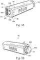
- the cap 109 can also include a second cutout in a shape of a USB port (USB cutout 109B ), proximate to or corresponding to a USB port 190 ( see Fig. 3A ).
- the cap 109 can include a third cutout in a shape of an audio jack (audio jack cutout 109C ), proximate to or corresponding to an audio jack port 200 ( see Fig. 3A ). It is understood that if other components of the metronome 100 are configured proximate to the cap 107 or the cap 109 , the corresponding cap can include a cutout for that component. For example, as shown in Fig. 3A , the cap 109 can include an on/off switch cutout 109D for the on/off switch 170 .
- the body 102 can include a cutout corresponding to a component of the metronome 100 . For example, as shown in Fig. 2B , the body 102 can include a cutout 102B to encompass the tempo controller 150 .
- the senor 110 can be any type of sensor capable of sensing a strike, a motion, a sound having a predetermined wavelength, and/or a vibration.
- the sensor can be a piezoelectric sensor, an accelerometer, and/or a microphone capable of detecting a predetermined wavelength.
- the sensor 110 can be a piezoelectric shock sensor.
- the sensor can be an accelerometer capable of sending the acceleration created by striking the metronome 100 by an instrument.
- the sensor can be a microphone capable of detecting the sound wavelength generated when the metronome 100 is struck by an instrument.
- the senor 110 can be positioned in a remote location, such as the side of the snare drum.
- the sensor 110 can includes a communication device that enables the sensor to communicate with the metronome controller 130 .
- the user can hit the side of the snare drum with the drum stick to activate or deactivate one or more of its built-in capabilities, such as tempo, volume, etc.
- a strike is sensed by the sensor 110 , which sends a change in sensor output signal to the processor.
- the processor having executable computer readable program codes executes a program logic which processes the change in sensor signal.
- the processor executes the computer readable program code to instruct the controller 130 to generate a signal to turn-off or turn-on the metronome 100 , mute or un-mute the metronome 100 , mute or un-mute the tempo or tap tempo, place the metronome 100 into a sleep mode or wake it up, or pause or un-pause the metronome 100 .
- the controller 130 in response to the signal received from the sensor 110 , can generate a signal and send it to a volume button board 132 to mute the metronome 100 .
- the volume button board 132 can be part of the board containing the controller 130 or can be a separate board as shown in Fig. 1 .
- the sensor 110 when the sensor 110 detects a plurality of hits or strikes, for example at least two hits, it determines the average time between each of the plurality of hits and calculates a new tempo based on the average calculated time between the plurality of hits. The metronome 100 then continues the tempo created by the user based on the user's plurality of hits.
- the metronome 100 can also have at least one speaker 120 that is capable of converting a tempo signal to an audible wave.
- the speaker 120 can also be in communication with the controller 130 or with a separate controller.
- the metronome 100 when the metronome 100 is turned-on, the metronome generates a tempo determined or set by a user. As stated above, the user can set the tempo by a plurality of hits to the metronome 100 or a sensor 110 (if the sensor is not part of the metronome). The metronome 100 then it determines the average time between each of the plurality of hits and calculates a new tempo based on the average calculated time between the plurality of hits. The metronome 100 then continues the tempo created by the user based on the user's plurality of hits. In another example, the metronome 100 can be pre-programmed so that an action of the user tells the tempo to start the pre-programmed tempo.
- the metronome 100 can be programmed so that when a user hits the metronome 100 three times, the metronome 100 plays a first tempo. If the user hits the metronome 100 four times, the metronome 100 plays a second tempo and so on.
- the controller 130 sends a signal to the speaker 120 to convert the tempo electrical signal to an audible wave so that the user can hear the tempo.
- the user can strike the metronome 100 with his/her musical instrument, such as a drum stick.
- the user can strike any part of the body 102 of the metronome 100 with a drum stick so that the sensor 110 can detect the strike.
- the user can strike a portion of the body 102 where the rod-like structures 108A , 108B , 108C , and 108D are respectively configured.
- the sensor 110 By striking the metronome 100 , the sensor 110 can detect at least one of motion, strike force, sound caused by, and/or the vibration caused by striking the metronome 100 .
- the sensor 110 in response to detecting the strike of the drum stick on the metronome 100 , can send a signal to the controller 130 , which in turn can send a signal to the speaker to mute the speaker 120 .
- the controller 130 can send a signal to the on/off switch 170 of the metronome 100 to turn off the metronome 100 or put it in a sleep mode.
- the controller 130 after receiving the signal from the sensor 110 , can provide a signal to the on/off switch 170 to turn off the metronome 100 .
- the controller 130 instead of or in addition to providing a signal to the on/off switch 170 , it provides a signal to a power source 172 .
- the power source 172 in response to receiving the signal from the controller 130 , can limit the power distribution to at least the sensor 110 and the controller 130 .
- the remaining components, such as the speaker 120 cannot receive power unless the power source 172 receives a second signal from the controller 130 commanding the power source 172 to also provide power to the remaining components of the metronome 100 , such as the speaker 120
- the controller 130 provides a signal to the on/off switch to turn off the metronome 100
- the user can turn on the metronome 100 by pressing the on/off switch 170.
- the metronome 100 when the metronome 100 is in a sleep mode, the user can turn on the metronome 100 by striking the metronome 100 with the drum stick.
- the power source 172 provides power to the sensor 110 and the controller 130
- the sensor 110 detects the force applied to the metronome 100 and, in response, sends a signal to the controller 130 .
- the controller 130 in response to receiving the signal from the sensor 110 , can send a signal to the power source 172 to provide power to the remaining components of the metronome, such as the speaker 120 .
- the tempo controller 150 is located proximate to the cap 107 .
- the tempo controller 150 includes a sleeve-like structure 150A .
- the sleeve-like structure can be made of any material.
- the material of the sleeve-like structure 150A is a type of material with a high coefficient of friction, such that a user can place an end of a drum stick on the sleeve-like structure 150A and place a force on the drum stick to turn the tempo controller 150 without the end of the drum stick slipping off the sleeve-like structure 150A before turning the tempo controller 150 .
- the sleeve-like structure 150A can have a coefficient of friction ( ⁇ ) of from less than 0.25 to more than 1.
- the coefficient of friction of the sleeve-like structure 150A can be in a range of from about 0.1 or less to about 1 or more, such as from about 0.25 to about 0.75, for example from about 0.3 to about 0.6, or from about 0.4 to about 0.5.
- Some exemplary materials that can be used as the sleeve-like structure 150A can be, but are not limited to, polymer based composition with or without a backing layer.
- the material for the sleeve-like structure 150A can be, but are not limited to, silicon, acetal (POM), nylon (PA), poyphthalamide (PPA), polyetherentherketone (PEEK), polyphenylene sulfide (PPS), polybutylene terephthalate (PBT), thermoplastic polyimide (TPI), polycarbonate (PC), polyetherimide (PEI), rubber, or a combination thereof, or other materials and/or compositions.
- POM acetal
- PA nylon
- PPA polyetherentherketone
- PES polyphenylene sulfide
- PBT polybutylene terephthalate
- TPI thermoplastic polyimide
- PC polycarbonate
- PEI polyetherimide
- rubber or a combination thereof, or other materials and/or compositions.
- the silicon based composition can be adhered to a gripping portion of the tempo controller 150 and can have one or more of the following shapes/patterns 150B : curved, non-linear, zigzag, concave, convex, ribbed, and/or flat.
- the shapes/patterns 150B are in a size so that when an end of the drum stick comes in contact with the shapes/patterns 150B , a sufficient surface area of the covering-like and/or sleeve-like structure 150A comes in contact with the end of the drum stick to create sufficient friction so that when the user pushes on the drum stick, the drum stick can rotate the tempo controller 150 .
- the tempo controller does not include a sleeve-like structure 150A ; however, the tempo controller 150 can include at least one depression having a sufficient size and depth such that when an end of a drum stick comes in contact with the depression, a sufficient surface area of the tempo controller 150 comes in contact with the end of the drum stick to create sufficient friction so that when the user pushes on the drum stick, the drum stick can rotate the tempo controller 150 .
- the tempo beats can be illustrated on the body 102 .
- the body 102 or at least a portion of the body 102 can be made of a material that can display an image, numbers, and/or letters.
- three sides of the body 102 can be made of a first material and the forth side 102C can be made of a second material capable of displaying an image, number, or letter.
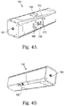
- the forth side 102C that is made of a second material can have a display 160 ( Fig. 4 ) and logic board capable of displaying an image, number, or letter on the second material.
- the logic board is connected to the forth side 102C .
- the logic board can be incorporated into a PCB having the controller 130 or can be a separate board that can be in communication with the controller 130.
- a volume controller 140 can be positioned on a part of the body 102 .
- the volume controller 140 can be on one of the side walls making the body 102 or can be at one of the end caps 107 , 109 .
- the volume controller can have an increase volume button and a decrease volume button.
- the volume button can be in any shape such as a triangle, as shown in Fig. 3A .
- the volume controller can be in a form of a knob that can be rotated in a first direction to increase the volume of the tempo and can be rotated in a second direction to decrease the volume of the tempo.
- Other types of volume controllers can also be incorporated into the metronome 100.
- Such volume controllers include, but are not limited to buttons, dials, knobs, rockers, or other devices.
- the body 102 and the knob 150 of the metronome 100 can be at least partially encapsulated or covered by a material 104 .
- the material 104 can be made of a material that is capable of absorbing or reducing the force of an impact by a drum stick or other instruments on the metronome 100 .
- the cover is designed to be at least partially transparent or at least allow the display to visible though the impact absorbing material 104 .
- An example of such a material is, but not limited to, silicone, rubber, cloth, vinyl, leather, and/or metal to name a few.
- the metronome 100 can include an accent controller 210 .
- the accent controller 210 can be positioned anywhere on the metronome 100 , such as on the body 102 or on one of the caps 107 , 109 .
- the metronome 100 can have at least one stand screw 180 .
- the stand screw 180 can be configured anywhere on the metronome 100 .
- it can be configured on one of the caps 107 and 109 , or on one of the edges of the body 102 .
- the user can press the power button or the on/off switch 170.
- the display 160 turns on.
- the display 160 can indicate that the metronome 100 is turned on by displaying a set of numbers, for example, the display 160 can display an indicator, such as a number, letter, or symbol. For example it can display the number "0000" to illustrate to the user that the display 160 is in a working condition.
- the display can also show a message, such as "HIT" "DRUM” "TO” “MUTE.” Other messages can also be programmed to be displayed. After the preprogrammed message has been displayed, the metronome 100 can go into a standby mode with a default tempo displaying on the display 160 .
- the display 160 can show the number "120."
- the metronome 100 can be programmed so that the speaker does not generate the sound of the default tempo.
- the metronome 100 can be programmed so that the speaker does generate the sound of the default tempo when the metronome 100 is first turned on.
- the default program is such that the metronome 100 does not sound the beats of the default tempo
- the user can start the sound by striking the metronome 100 by the drum stick.
- the user can strike the metronome 100 several times. The metronome 100 takes the average of the time between each strike and the tempo and will then play the new tempo.
- the sound can be heard through the speaker 120 .
- the sound can be heard only through the headphone and no sound can be heard from the speaker 120 .
- the only way to turn the sound on or off can be by hitting the metronome 100 , by pressing the on/off switch 170 , or by pressing on the volume button 140 until the sound can no longer be heard.
- the user when the metronome 100 is making a sound, the user can stop the sound by striking the metronome 100 . After the metronome 100 has been struck, the sound mutes; however, the display 160 can still illustrate the beats per minute of the tempo that can be heard from the metronome 100 if it gets hit again to unmute or activate the metronome 100 .
- a single button or knob can activate and/or control a plurality of functions.
- the tempo controller 150 can be programed such that by selecting a first function, the tempo controller 150 can function as a volume controller and in a second function the tempo controller 150 can function as a tempo controller.
- the metronome 100 can have a select functionality button or a function selector button.
- the sensor 110 of the metronome 100 can be programed such that if the drum stick is rolled or glided on the metronome 100 , the functionality can change.
- the sound emission can be re-activated by either striking the metronome 100 or by pressing the volume controller 140 to increase or decrease the volume.
- the display 160 can illustrate a number associated with the level of the volume. The volume numbers can range from 1 to 10 with "1" being mute and "10" being the loudest sound the speaker 120 is capable of generating.
- the user can turn the tempo controller 150 .
- the tempo controller 150 For example, turning the tempo controller 150 clockwise can increase the tempo, while turning the tempo controller 150 counter-clockwise can decrease the tempo.
- the display 160 can illustrate the tempo as the user turns the tempo controller 150 .
- the tempo controller can be turned by using a musical instrument, such as a drum stick, or by hand.
- the user can turn off the metronome 100 by pressing the on/off switch 170 .
- the display 160 can illustrate a message such as, for non-limiting example "BYE,” “DRUM,” “DONE,” “BEER,” and “REST” to name a few.
- the display 160 can be blank.
- the tempo can increment evenly as the user turns the tempo controller 150 , or progressively accelerate or decelerate as the user turns the tempo controller 150 faster or slower either by hand or his musical instrument.
- the tempo can be changed by the user striking the metronome 100 a plurality of times, which is sensed by the sensor 110 causing the sensor 110 to send a signal to the controller 130 .
- the metronome 100 can take the average time between per each of the plurality of strikes as the tempo and continue playing the tempo.
- the display 160 can illustrate the battery level.
- the controller 130 can also run a self-diagnostic before start of each session to confirm that the metronome 100 is in working condition. In one example, if the metronome is not in a working condition, the display can state the reason for the metronome 100 not working properly, by flashing the display, or displaying a different color. Alternatively, if the controller 130 discovers an issue with metronome 100 , the speaker 120 can generate a sound.
- other messages can be depicted on the display.
- the messages can be stored in a memory that is incorporated in the controller 130 and can be depicted on the display when certain conditions occur. For example, when the device is about to turn on or off the display can depict the word "ON” or "OFF” respectively.
- a message such as "10% PWR LIFE LEFT” or "5 MIN of PLAY TIME LEFT.”
- Other messages, sounds, and/or information can be programmed by connecting the metronome 100 via its USB port 190 to a device. Additionally, the USB port 190 can be connected to a power source to recharge the power source 172 of the metronome 100 .
- the metronome 100 via its USB port 190 can be connected to a computer device, such as a tablet, laptop, desktop, and/or a smart phone.
- the computer device can have a program or an application that allows the user to program the metronome 100 . For example, it can allow the user to program a list of tempo settings.
- the metronome 100 can be programmed such that when the user applies a single strike to the metronome 100 the metronome 100 can play a first tempo.
- the metronome can play a second pre-programmed tempo different from the first tempo. If the user applies three consecutive strikes to the metronome 100 , then the metronome can play a third pre-programmed tempo different from the second tempo.
- the third tempo can be similar to the first tempo or can be different from the first tempo, depending the user's applied settings while the metronome 100 was connected to a computer.
- the metronome 100 can be programmed such that if it is hit in a first area, then the metronome can play a first tempo and if it is hit in a second area, the metronome 100 can play a second tempo and so on.
- the metronome 100 can be programmed to take the average time between each of the plurality of strikes and the tempo and continue playing the tempo.
- a drummer who is preparing for a live performance has the list of the songs and the order which they will be performed. This is commonly known as a 'set list'. Each song in the set list can have a different tempo.
- the drummer can pre-program the metronome 100 , using the program and/or the application, with the desired tempo settings for the set list. During the performance, the drummer can adjust the tempo to the next or previous song in the set list by striking the metronome 100 in the pre-programmed predetermined area and/or spot.
Landscapes
- Engineering & Computer Science (AREA)
- Multimedia (AREA)
- Physics & Mathematics (AREA)
- Acoustics & Sound (AREA)
- General Physics & Mathematics (AREA)
- Electrophonic Musical Instruments (AREA)
Claims (13)
- Metronom (100), umfassend:einen ersten Sensor (110) zum Erfassen von Schlägen auf das Metronom;einen Lautsprecher (120), undeine Steuerung (130) in Kommunikation mit dem ersten Sensor (110), wobei, wenn die Steuerung (130) ein Signal von dem ersten Sensor (110) empfängt, das eine vorbestimmte Anzahl an Schlägen auf das Metronom (100) angibt, die Steuerung (130) als Reaktion ein Signal zum Stummschalten oder Aufheben der Stummschaltung des Lautsprechers (120) erzeugt, und wobei, wenn die Steuerung (130) ein Signal von dem ersten Sensor (100) empfängt, das ein Ereignis angibt, das sich von der vorbestimmten Anzahl an Schlägen auf das Metronom (100) unterscheidet, die Steuerung (130) als Reaktion ein Signal erzeugt, um eines von (i) einem Tempo basierend auf einer Eigenschaft des Ereignisses festzulegen, (ii) das Metronom (100) basierend auf einer Eigenschaft des Ereignisses ein- und auszuschalten, und (iii) das Metronom (100) in eines von einem Schlafmodus oder einem Wachmodus zu versetzen.
- Metronom (100) nach Anspruch 1, wobei das Ereignis zumindest eines von einem Schlag und einer Vielzahl von Schlägen ist,wobei das Tempo auf einer durchschnittlichen Zeit zwischen jedem aus der Vielzahl von Schlägen basiert, undwobei das Tempo beginnt, einen Takt als eine Fortsetzung der Vielzahl von Schlägen zu spielen.
- Metronom (100) nach Anspruch 2, ferner umfassend einen Prozessor, der konfiguriert ist, um die durchschnittliche Zeit zwischen jedem aus der Vielzahl von Schlägen zu berechnen.
- Metronom (100) nach Anspruch 1, wobei der erste Sensor (110) in der Lage ist, zumindest eines von einem Schlag, einer Bewegung, einem Ton einer vorbestimmten Wellenlänge und einer Vibration zu erfassen.
- Metronom (100) nach Anspruch 1, wobei die Steuerung (130) in Kommunikation mit einem Lautsprecher (120) ist und konfiguriert ist, um die Lautstärke des Lautsprechers (120) zumindest eines von zu erhöhen oder zu verringern.
- Metronom (100) nach Anspruch 1, ferner umfassend eine Temposteuerung (150), die ausgelegt ist, um das Tempo einzustellen, und eine Tempoanzeige in Kommunikation mit der Temposteuerung (150), wobei die Tempoanzeige das Tempo veranschaulicht, das durch die Temposteuerung (150) festgelegt ist.
- Metronom (100) nach Anspruch 6, wobei die Temposteuerung (150) gestaltet ist, um einen Teil einer Einstellvorrichtung aufzunehmen, sodass ein Benutzer das Tempo des Metronoms (100) mit der Einstellvorrichtung einstellen kann.
- Metronom (100) nach Anspruch 1, ferner umfassend zumindest eines von einem Einschaltknopf (170), zumindest einem Lautstärkeknopf (132), einem Akzentknopf, einer Audiobuchse (200) und einem USB-Anschluss (190).
- Metronom (100) nach Anspruch 1, ferner umfassend zumindest ein Montageloch.
- Metronom (100) nach Anspruch 1, ferner umfassend einen Körper (102), der ein stoßabsorbierendes Material (104) aufweist, um eine Kraft abzufedern, die mit dem Ereignis verbunden ist.
- Metronom (100) nach Anspruch 10, wobei das stoßabsorbierende Material (104) in einer Form einer austauschbaren Hülse (150A) ist.
- Metronom (100) nach Anspruch 1, ferner umfassend einen zweiten Sensor (110), der in der Lage ist, zumindest eines von einem Schlag, einer Bewegung, einem Ton einer vorbestimmten Wellenlänge und einer Vibration zu erfassen.
- Verfahren zum Modifizieren einer Ausgabe eines Metronoms nach Anspruch 1, umfassend die folgenden Schritte:Schlagen des Metronoms (100) eine vorbestimmte Anzahl an Malen;automatisches Einstellen des Tempos basierend auf der durchschnittlichen Menge an Zeit zwischen jedem aus der vorbestimmten Anzahl an Schlägen;Spielen des Tempos von einem letzten Schlag; undSchlagen des Metronoms (100) eine zweite vorbestimmte Anzahl an Malen, um den Lautsprecher des Metronoms (100) eines von stummzuschalten oder die Stummschaltung aufzuheben.
Priority Applications (1)
| Application Number | Priority Date | Filing Date | Title |
|---|---|---|---|
| EP22163993.3A EP4075207A1 (de) | 2015-11-03 | 2016-11-02 | Kontaktabhängiges metronom |
Applications Claiming Priority (2)
| Application Number | Priority Date | Filing Date | Title |
|---|---|---|---|
| US201562250367P | 2015-11-03 | 2015-11-03 | |
| PCT/US2016/060137 WO2017079317A1 (en) | 2015-11-03 | 2016-11-02 | Contact responsive metronome |
Related Child Applications (2)
| Application Number | Title | Priority Date | Filing Date |
|---|---|---|---|
| EP22163993.3A Division EP4075207A1 (de) | 2015-11-03 | 2016-11-02 | Kontaktabhängiges metronom |
| EP22163993.3A Division-Into EP4075207A1 (de) | 2015-11-03 | 2016-11-02 | Kontaktabhängiges metronom |
Publications (3)
| Publication Number | Publication Date |
|---|---|
| EP3371659A1 EP3371659A1 (de) | 2018-09-12 |
| EP3371659A4 EP3371659A4 (de) | 2019-07-10 |
| EP3371659B1 true EP3371659B1 (de) | 2022-05-04 |
Family
ID=58662674
Family Applications (2)
| Application Number | Title | Priority Date | Filing Date |
|---|---|---|---|
| EP16862889.9A Active EP3371659B1 (de) | 2015-11-03 | 2016-11-02 | Kontaktabhängiges metronom |
| EP22163993.3A Pending EP4075207A1 (de) | 2015-11-03 | 2016-11-02 | Kontaktabhängiges metronom |
Family Applications After (1)
| Application Number | Title | Priority Date | Filing Date |
|---|---|---|---|
| EP22163993.3A Pending EP4075207A1 (de) | 2015-11-03 | 2016-11-02 | Kontaktabhängiges metronom |
Country Status (3)
| Country | Link |
|---|---|
| US (2) | US10671024B2 (de) |
| EP (2) | EP3371659B1 (de) |
| WO (1) | WO2017079317A1 (de) |
Families Citing this family (4)
| Publication number | Priority date | Publication date | Assignee | Title |
|---|---|---|---|---|
| EP3371659B1 (de) * | 2015-11-03 | 2022-05-04 | Konrad Meissner | Kontaktabhängiges metronom |
| US11921469B2 (en) * | 2015-11-03 | 2024-03-05 | Clikbrik, LLC | Contact responsive metronome |
| WO2019081416A1 (en) | 2017-10-23 | 2019-05-02 | Sony Corporation | P ACTIVE MATERIALS FOR ORGANIC PHOTOELECTRIC CONVERSION LAYERS IN ORGANIC PHOTODIODS. |
| US12030575B2 (en) * | 2020-10-27 | 2024-07-09 | Shimano Inc. | Rider-posture changing device and control system of human-powered vehicle |
Family Cites Families (9)
| Publication number | Priority date | Publication date | Assignee | Title |
|---|---|---|---|---|
| US6525259B2 (en) * | 2000-11-28 | 2003-02-25 | John Sagastegui | Cadence-providing conga drum practice pad assembly and method |
| AU2003258442A1 (en) * | 2002-09-18 | 2004-04-08 | Michael Boxer | Metronome |
| US7081577B2 (en) * | 2003-05-27 | 2006-07-25 | Seiko Instruments Inc. | Electronic metronome |
| US7385128B2 (en) * | 2004-12-06 | 2008-06-10 | Tailgaitor, Inc. | Metronome with projected beat image |
| JP4714479B2 (ja) * | 2005-02-21 | 2011-06-29 | セイコーインスツル株式会社 | 電子式メトロノームおよび電子式メトロノームのテンポ設定方法 |
| US20070028746A1 (en) * | 2005-08-04 | 2007-02-08 | Michael Herring | Multi-Funtional Pick For A Stringed Instrument |
| DE112006003024T5 (de) * | 2005-10-25 | 2008-10-09 | Onboard Research Corp., Carrollton | Verfahren eines und System für ein Zeiteinteilungs-Training |
| EP3371659B1 (de) * | 2015-11-03 | 2022-05-04 | Konrad Meissner | Kontaktabhängiges metronom |
| USD798748S1 (en) * | 2015-12-02 | 2017-10-03 | Clikbrik, LLC | Metronome |
-
2016
- 2016-11-02 EP EP16862889.9A patent/EP3371659B1/de active Active
- 2016-11-02 EP EP22163993.3A patent/EP4075207A1/de active Pending
- 2016-11-02 US US15/772,517 patent/US10671024B2/en active Active
- 2016-11-02 WO PCT/US2016/060137 patent/WO2017079317A1/en not_active Ceased
-
2020
- 2020-05-13 US US15/931,581 patent/US10962931B2/en active Active
Also Published As
| Publication number | Publication date |
|---|---|
| US20190079462A1 (en) | 2019-03-14 |
| US20200310358A1 (en) | 2020-10-01 |
| EP4075207A1 (de) | 2022-10-19 |
| EP3371659A4 (de) | 2019-07-10 |
| EP3371659A1 (de) | 2018-09-12 |
| US10962931B2 (en) | 2021-03-30 |
| WO2017079317A1 (en) | 2017-05-11 |
| US10671024B2 (en) | 2020-06-02 |
Similar Documents
| Publication | Publication Date | Title |
|---|---|---|
| US10962931B2 (en) | Contact responsive metronome | |
| JP2010122268A (ja) | 電子鍵盤楽器の楽音制御装置 | |
| US8054174B1 (en) | Referee's wireless horn indicator system having sensor alerts | |
| US20160030829A1 (en) | Tennis scoring and display systems and methods | |
| JP5016942B2 (ja) | 音楽練習支援装置 | |
| US11921469B2 (en) | Contact responsive metronome | |
| US20160246377A1 (en) | Modifying haptic effects for slow motion | |
| JP5320781B2 (ja) | 電子楽器用力覚制御装置 | |
| JP2013088780A (ja) | 発光制御装置 | |
| CN104866078A (zh) | 电子设备的控制方法、控制装置及电子设备 | |
| CN107626104A (zh) | 一种游戏手柄的多功能控制方法 | |
| KR101500268B1 (ko) | 가변 마운팅 음파 터치패드 | |
| US20040255756A1 (en) | Electronic metronome | |
| JP2011064728A (ja) | 電子鍵盤楽器 | |
| JP3167234U (ja) | ハンドベル構造 | |
| KR20190054003A (ko) | 드럼스틱을 이용한 전자악보 | |
| TWI275988B (en) | Mouse using sound frequency transmission | |
| JP2003275465A5 (de) | ||
| JP5975412B1 (ja) | 遊技機 | |
| JP2015225332A5 (de) | ||
| JP4442531B2 (ja) | 電子鍵盤楽器 | |
| JP6832840B2 (ja) | 操作玩具 | |
| JP2016202927A (ja) | 遊技機 | |
| JP2007289772A5 (de) | ||
| KR100887980B1 (ko) | 응원도구 및 그에 따른 제어방법 |
Legal Events
| Date | Code | Title | Description |
|---|---|---|---|
| STAA | Information on the status of an ep patent application or granted ep patent |
Free format text: STATUS: THE INTERNATIONAL PUBLICATION HAS BEEN MADE |
|
| PUAI | Public reference made under article 153(3) epc to a published international application that has entered the european phase |
Free format text: ORIGINAL CODE: 0009012 |
|
| STAA | Information on the status of an ep patent application or granted ep patent |
Free format text: STATUS: REQUEST FOR EXAMINATION WAS MADE |
|
| 17P | Request for examination filed |
Effective date: 20180430 |
|
| AK | Designated contracting states |
Kind code of ref document: A1 Designated state(s): AL AT BE BG CH CY CZ DE DK EE ES FI FR GB GR HR HU IE IS IT LI LT LU LV MC MK MT NL NO PL PT RO RS SE SI SK SM TR |
|
| AX | Request for extension of the european patent |
Extension state: BA ME |
|
| DAV | Request for validation of the european patent (deleted) | ||
| DAX | Request for extension of the european patent (deleted) | ||
| A4 | Supplementary search report drawn up and despatched |
Effective date: 20190606 |
|
| RIC1 | Information provided on ipc code assigned before grant |
Ipc: G04F 5/02 20060101ALI20190531BHEP Ipc: G04F 5/00 20060101AFI20190531BHEP |
|
| GRAP | Despatch of communication of intention to grant a patent |
Free format text: ORIGINAL CODE: EPIDOSNIGR1 |
|
| STAA | Information on the status of an ep patent application or granted ep patent |
Free format text: STATUS: GRANT OF PATENT IS INTENDED |
|
| INTG | Intention to grant announced |
Effective date: 20211202 |
|
| GRAS | Grant fee paid |
Free format text: ORIGINAL CODE: EPIDOSNIGR3 |
|
| GRAA | (expected) grant |
Free format text: ORIGINAL CODE: 0009210 |
|
| STAA | Information on the status of an ep patent application or granted ep patent |
Free format text: STATUS: THE PATENT HAS BEEN GRANTED |
|
| AK | Designated contracting states |
Kind code of ref document: B1 Designated state(s): AL AT BE BG CH CY CZ DE DK EE ES FI FR GB GR HR HU IE IS IT LI LT LU LV MC MK MT NL NO PL PT RO RS SE SI SK SM TR |
|
| REG | Reference to a national code |
Ref country code: GB Ref legal event code: FG4D |
|
| REG | Reference to a national code |
Ref country code: CH Ref legal event code: EP |
|
| REG | Reference to a national code |
Ref country code: AT Ref legal event code: REF Ref document number: 1489725 Country of ref document: AT Kind code of ref document: T Effective date: 20220515 |
|
| REG | Reference to a national code |
Ref country code: DE Ref legal event code: R096 Ref document number: 602016071892 Country of ref document: DE |
|
| REG | Reference to a national code |
Ref country code: IE Ref legal event code: FG4D |
|
| REG | Reference to a national code |
Ref country code: LT Ref legal event code: MG9D |
|
| REG | Reference to a national code |
Ref country code: NL Ref legal event code: MP Effective date: 20220504 |
|
| REG | Reference to a national code |
Ref country code: AT Ref legal event code: MK05 Ref document number: 1489725 Country of ref document: AT Kind code of ref document: T Effective date: 20220504 |
|
| PG25 | Lapsed in a contracting state [announced via postgrant information from national office to epo] |
Ref country code: SE Free format text: LAPSE BECAUSE OF FAILURE TO SUBMIT A TRANSLATION OF THE DESCRIPTION OR TO PAY THE FEE WITHIN THE PRESCRIBED TIME-LIMIT Effective date: 20220504 Ref country code: PT Free format text: LAPSE BECAUSE OF FAILURE TO SUBMIT A TRANSLATION OF THE DESCRIPTION OR TO PAY THE FEE WITHIN THE PRESCRIBED TIME-LIMIT Effective date: 20220905 Ref country code: NO Free format text: LAPSE BECAUSE OF FAILURE TO SUBMIT A TRANSLATION OF THE DESCRIPTION OR TO PAY THE FEE WITHIN THE PRESCRIBED TIME-LIMIT Effective date: 20220804 Ref country code: NL Free format text: LAPSE BECAUSE OF FAILURE TO SUBMIT A TRANSLATION OF THE DESCRIPTION OR TO PAY THE FEE WITHIN THE PRESCRIBED TIME-LIMIT Effective date: 20220504 Ref country code: LT Free format text: LAPSE BECAUSE OF FAILURE TO SUBMIT A TRANSLATION OF THE DESCRIPTION OR TO PAY THE FEE WITHIN THE PRESCRIBED TIME-LIMIT Effective date: 20220504 Ref country code: HR Free format text: LAPSE BECAUSE OF FAILURE TO SUBMIT A TRANSLATION OF THE DESCRIPTION OR TO PAY THE FEE WITHIN THE PRESCRIBED TIME-LIMIT Effective date: 20220504 Ref country code: GR Free format text: LAPSE BECAUSE OF FAILURE TO SUBMIT A TRANSLATION OF THE DESCRIPTION OR TO PAY THE FEE WITHIN THE PRESCRIBED TIME-LIMIT Effective date: 20220805 Ref country code: FI Free format text: LAPSE BECAUSE OF FAILURE TO SUBMIT A TRANSLATION OF THE DESCRIPTION OR TO PAY THE FEE WITHIN THE PRESCRIBED TIME-LIMIT Effective date: 20220504 Ref country code: ES Free format text: LAPSE BECAUSE OF FAILURE TO SUBMIT A TRANSLATION OF THE DESCRIPTION OR TO PAY THE FEE WITHIN THE PRESCRIBED TIME-LIMIT Effective date: 20220504 Ref country code: BG Free format text: LAPSE BECAUSE OF FAILURE TO SUBMIT A TRANSLATION OF THE DESCRIPTION OR TO PAY THE FEE WITHIN THE PRESCRIBED TIME-LIMIT Effective date: 20220804 Ref country code: AT Free format text: LAPSE BECAUSE OF FAILURE TO SUBMIT A TRANSLATION OF THE DESCRIPTION OR TO PAY THE FEE WITHIN THE PRESCRIBED TIME-LIMIT Effective date: 20220504 |
|
| PG25 | Lapsed in a contracting state [announced via postgrant information from national office to epo] |
Ref country code: RS Free format text: LAPSE BECAUSE OF FAILURE TO SUBMIT A TRANSLATION OF THE DESCRIPTION OR TO PAY THE FEE WITHIN THE PRESCRIBED TIME-LIMIT Effective date: 20220504 Ref country code: PL Free format text: LAPSE BECAUSE OF FAILURE TO SUBMIT A TRANSLATION OF THE DESCRIPTION OR TO PAY THE FEE WITHIN THE PRESCRIBED TIME-LIMIT Effective date: 20220504 Ref country code: LV Free format text: LAPSE BECAUSE OF FAILURE TO SUBMIT A TRANSLATION OF THE DESCRIPTION OR TO PAY THE FEE WITHIN THE PRESCRIBED TIME-LIMIT Effective date: 20220504 Ref country code: IS Free format text: LAPSE BECAUSE OF FAILURE TO SUBMIT A TRANSLATION OF THE DESCRIPTION OR TO PAY THE FEE WITHIN THE PRESCRIBED TIME-LIMIT Effective date: 20220904 |
|
| PG25 | Lapsed in a contracting state [announced via postgrant information from national office to epo] |
Ref country code: SM Free format text: LAPSE BECAUSE OF FAILURE TO SUBMIT A TRANSLATION OF THE DESCRIPTION OR TO PAY THE FEE WITHIN THE PRESCRIBED TIME-LIMIT Effective date: 20220504 Ref country code: SK Free format text: LAPSE BECAUSE OF FAILURE TO SUBMIT A TRANSLATION OF THE DESCRIPTION OR TO PAY THE FEE WITHIN THE PRESCRIBED TIME-LIMIT Effective date: 20220504 Ref country code: RO Free format text: LAPSE BECAUSE OF FAILURE TO SUBMIT A TRANSLATION OF THE DESCRIPTION OR TO PAY THE FEE WITHIN THE PRESCRIBED TIME-LIMIT Effective date: 20220504 Ref country code: EE Free format text: LAPSE BECAUSE OF FAILURE TO SUBMIT A TRANSLATION OF THE DESCRIPTION OR TO PAY THE FEE WITHIN THE PRESCRIBED TIME-LIMIT Effective date: 20220504 Ref country code: DK Free format text: LAPSE BECAUSE OF FAILURE TO SUBMIT A TRANSLATION OF THE DESCRIPTION OR TO PAY THE FEE WITHIN THE PRESCRIBED TIME-LIMIT Effective date: 20220504 Ref country code: CZ Free format text: LAPSE BECAUSE OF FAILURE TO SUBMIT A TRANSLATION OF THE DESCRIPTION OR TO PAY THE FEE WITHIN THE PRESCRIBED TIME-LIMIT Effective date: 20220504 |
|
| REG | Reference to a national code |
Ref country code: DE Ref legal event code: R097 Ref document number: 602016071892 Country of ref document: DE |
|
| PLBE | No opposition filed within time limit |
Free format text: ORIGINAL CODE: 0009261 |
|
| STAA | Information on the status of an ep patent application or granted ep patent |
Free format text: STATUS: NO OPPOSITION FILED WITHIN TIME LIMIT |
|
| PG25 | Lapsed in a contracting state [announced via postgrant information from national office to epo] |
Ref country code: AL Free format text: LAPSE BECAUSE OF FAILURE TO SUBMIT A TRANSLATION OF THE DESCRIPTION OR TO PAY THE FEE WITHIN THE PRESCRIBED TIME-LIMIT Effective date: 20220504 |
|
| 26N | No opposition filed |
Effective date: 20230207 |
|
| PG25 | Lapsed in a contracting state [announced via postgrant information from national office to epo] |
Ref country code: SI Free format text: LAPSE BECAUSE OF FAILURE TO SUBMIT A TRANSLATION OF THE DESCRIPTION OR TO PAY THE FEE WITHIN THE PRESCRIBED TIME-LIMIT Effective date: 20220504 |
|
| PG25 | Lapsed in a contracting state [announced via postgrant information from national office to epo] |
Ref country code: MC Free format text: LAPSE BECAUSE OF FAILURE TO SUBMIT A TRANSLATION OF THE DESCRIPTION OR TO PAY THE FEE WITHIN THE PRESCRIBED TIME-LIMIT Effective date: 20220504 |
|
| REG | Reference to a national code |
Ref country code: CH Ref legal event code: PL |
|
| REG | Reference to a national code |
Ref country code: BE Ref legal event code: MM Effective date: 20221130 |
|
| PG25 | Lapsed in a contracting state [announced via postgrant information from national office to epo] |
Ref country code: LI Free format text: LAPSE BECAUSE OF NON-PAYMENT OF DUE FEES Effective date: 20221130 Ref country code: CH Free format text: LAPSE BECAUSE OF NON-PAYMENT OF DUE FEES Effective date: 20221130 |
|
| PG25 | Lapsed in a contracting state [announced via postgrant information from national office to epo] |
Ref country code: LU Free format text: LAPSE BECAUSE OF NON-PAYMENT OF DUE FEES Effective date: 20221102 |
|
| PG25 | Lapsed in a contracting state [announced via postgrant information from national office to epo] |
Ref country code: IE Free format text: LAPSE BECAUSE OF NON-PAYMENT OF DUE FEES Effective date: 20221102 |
|
| PG25 | Lapsed in a contracting state [announced via postgrant information from national office to epo] |
Ref country code: BE Free format text: LAPSE BECAUSE OF NON-PAYMENT OF DUE FEES Effective date: 20221130 |
|
| PG25 | Lapsed in a contracting state [announced via postgrant information from national office to epo] |
Ref country code: IT Free format text: LAPSE BECAUSE OF FAILURE TO SUBMIT A TRANSLATION OF THE DESCRIPTION OR TO PAY THE FEE WITHIN THE PRESCRIBED TIME-LIMIT Effective date: 20220504 |
|
| PG25 | Lapsed in a contracting state [announced via postgrant information from national office to epo] |
Ref country code: HU Free format text: LAPSE BECAUSE OF FAILURE TO SUBMIT A TRANSLATION OF THE DESCRIPTION OR TO PAY THE FEE WITHIN THE PRESCRIBED TIME-LIMIT; INVALID AB INITIO Effective date: 20161102 |
|
| PG25 | Lapsed in a contracting state [announced via postgrant information from national office to epo] |
Ref country code: CY Free format text: LAPSE BECAUSE OF FAILURE TO SUBMIT A TRANSLATION OF THE DESCRIPTION OR TO PAY THE FEE WITHIN THE PRESCRIBED TIME-LIMIT Effective date: 20220504 |
|
| PG25 | Lapsed in a contracting state [announced via postgrant information from national office to epo] |
Ref country code: MK Free format text: LAPSE BECAUSE OF FAILURE TO SUBMIT A TRANSLATION OF THE DESCRIPTION OR TO PAY THE FEE WITHIN THE PRESCRIBED TIME-LIMIT Effective date: 20220504 |
|
| PG25 | Lapsed in a contracting state [announced via postgrant information from national office to epo] |
Ref country code: MT Free format text: LAPSE BECAUSE OF FAILURE TO SUBMIT A TRANSLATION OF THE DESCRIPTION OR TO PAY THE FEE WITHIN THE PRESCRIBED TIME-LIMIT Effective date: 20220504 |
|
| PG25 | Lapsed in a contracting state [announced via postgrant information from national office to epo] |
Ref country code: BG Free format text: LAPSE BECAUSE OF FAILURE TO SUBMIT A TRANSLATION OF THE DESCRIPTION OR TO PAY THE FEE WITHIN THE PRESCRIBED TIME-LIMIT Effective date: 20220504 |
|
| PG25 | Lapsed in a contracting state [announced via postgrant information from national office to epo] |
Ref country code: BG Free format text: LAPSE BECAUSE OF FAILURE TO SUBMIT A TRANSLATION OF THE DESCRIPTION OR TO PAY THE FEE WITHIN THE PRESCRIBED TIME-LIMIT Effective date: 20220504 |
|
| PG25 | Lapsed in a contracting state [announced via postgrant information from national office to epo] |
Ref country code: TR Free format text: LAPSE BECAUSE OF FAILURE TO SUBMIT A TRANSLATION OF THE DESCRIPTION OR TO PAY THE FEE WITHIN THE PRESCRIBED TIME-LIMIT Effective date: 20220504 |
|
| PGFP | Annual fee paid to national office [announced via postgrant information from national office to epo] |
Ref country code: DE Payment date: 20251119 Year of fee payment: 10 |
|
| PGFP | Annual fee paid to national office [announced via postgrant information from national office to epo] |
Ref country code: GB Payment date: 20251118 Year of fee payment: 10 |
|
| PGFP | Annual fee paid to national office [announced via postgrant information from national office to epo] |
Ref country code: FR Payment date: 20251121 Year of fee payment: 10 |