EP3371506B1 - Einrichtung zum betanken von kraftfahrzeugen mit verflüssigtem gas - Google Patents
Einrichtung zum betanken von kraftfahrzeugen mit verflüssigtem gas Download PDFInfo
- Publication number
- EP3371506B1 EP3371506B1 EP16788660.5A EP16788660A EP3371506B1 EP 3371506 B1 EP3371506 B1 EP 3371506B1 EP 16788660 A EP16788660 A EP 16788660A EP 3371506 B1 EP3371506 B1 EP 3371506B1
- Authority
- EP
- European Patent Office
- Prior art keywords
- facility
- pipeline
- annular space
- line
- storage container
- Prior art date
- Legal status (The legal status is an assumption and is not a legal conclusion. Google has not performed a legal analysis and makes no representation as to the accuracy of the status listed.)
- Active
Links
Images



Classifications
-
- B—PERFORMING OPERATIONS; TRANSPORTING
- B67—OPENING, CLOSING OR CLEANING BOTTLES, JARS OR SIMILAR CONTAINERS; LIQUID HANDLING
- B67D—DISPENSING, DELIVERING OR TRANSFERRING LIQUIDS, NOT OTHERWISE PROVIDED FOR
- B67D7/00—Apparatus or devices for transferring liquids from bulk storage containers or reservoirs into vehicles or into portable containers, e.g. for retail sale purposes
- B67D7/04—Apparatus or devices for transferring liquids from bulk storage containers or reservoirs into vehicles or into portable containers, e.g. for retail sale purposes for transferring fuels, lubricants or mixed fuels and lubricants
- B67D7/0476—Vapour recovery systems
- B67D7/0478—Vapour recovery systems constructional features or components
-
- F—MECHANICAL ENGINEERING; LIGHTING; HEATING; WEAPONS; BLASTING
- F17—STORING OR DISTRIBUTING GASES OR LIQUIDS
- F17C—VESSELS FOR CONTAINING OR STORING COMPRESSED, LIQUEFIED OR SOLIDIFIED GASES; FIXED-CAPACITY GAS-HOLDERS; FILLING VESSELS WITH, OR DISCHARGING FROM VESSELS, COMPRESSED, LIQUEFIED, OR SOLIDIFIED GASES
- F17C5/00—Methods or apparatus for filling containers with liquefied, solidified, or compressed gases under pressures
- F17C5/02—Methods or apparatus for filling containers with liquefied, solidified, or compressed gases under pressures for filling with liquefied gases
- F17C5/04—Methods or apparatus for filling containers with liquefied, solidified, or compressed gases under pressures for filling with liquefied gases requiring the use of refrigeration, e.g. filling with helium or hydrogen
-
- B—PERFORMING OPERATIONS; TRANSPORTING
- B67—OPENING, CLOSING OR CLEANING BOTTLES, JARS OR SIMILAR CONTAINERS; LIQUID HANDLING
- B67D—DISPENSING, DELIVERING OR TRANSFERRING LIQUIDS, NOT OTHERWISE PROVIDED FOR
- B67D7/00—Apparatus or devices for transferring liquids from bulk storage containers or reservoirs into vehicles or into portable containers, e.g. for retail sale purposes
- B67D7/06—Details or accessories
- B67D7/42—Filling nozzles
- B67D7/54—Filling nozzles with means for preventing escape of liquid or vapour or for recovering escaped liquid or vapour
-
- B—PERFORMING OPERATIONS; TRANSPORTING
- B67—OPENING, CLOSING OR CLEANING BOTTLES, JARS OR SIMILAR CONTAINERS; LIQUID HANDLING
- B67D—DISPENSING, DELIVERING OR TRANSFERRING LIQUIDS, NOT OTHERWISE PROVIDED FOR
- B67D7/00—Apparatus or devices for transferring liquids from bulk storage containers or reservoirs into vehicles or into portable containers, e.g. for retail sale purposes
- B67D7/06—Details or accessories
- B67D7/78—Arrangements of storage tanks, reservoirs or pipe-lines
-
- F—MECHANICAL ENGINEERING; LIGHTING; HEATING; WEAPONS; BLASTING
- F17—STORING OR DISTRIBUTING GASES OR LIQUIDS
- F17C—VESSELS FOR CONTAINING OR STORING COMPRESSED, LIQUEFIED OR SOLIDIFIED GASES; FIXED-CAPACITY GAS-HOLDERS; FILLING VESSELS WITH, OR DISCHARGING FROM VESSELS, COMPRESSED, LIQUEFIED, OR SOLIDIFIED GASES
- F17C2205/00—Vessel construction, in particular mounting arrangements, attachments or identifications means
- F17C2205/03—Fluid connections, filters, valves, closure means or other attachments
- F17C2205/0302—Fittings, valves, filters, or components in connection with the gas storage device
- F17C2205/0352—Pipes
- F17C2205/0355—Insulation thereof
-
- F—MECHANICAL ENGINEERING; LIGHTING; HEATING; WEAPONS; BLASTING
- F17—STORING OR DISTRIBUTING GASES OR LIQUIDS
- F17C—VESSELS FOR CONTAINING OR STORING COMPRESSED, LIQUEFIED OR SOLIDIFIED GASES; FIXED-CAPACITY GAS-HOLDERS; FILLING VESSELS WITH, OR DISCHARGING FROM VESSELS, COMPRESSED, LIQUEFIED, OR SOLIDIFIED GASES
- F17C2205/00—Vessel construction, in particular mounting arrangements, attachments or identifications means
- F17C2205/03—Fluid connections, filters, valves, closure means or other attachments
- F17C2205/0302—Fittings, valves, filters, or components in connection with the gas storage device
- F17C2205/0352—Pipes
- F17C2205/0358—Pipes coaxial
-
- F—MECHANICAL ENGINEERING; LIGHTING; HEATING; WEAPONS; BLASTING
- F17—STORING OR DISTRIBUTING GASES OR LIQUIDS
- F17C—VESSELS FOR CONTAINING OR STORING COMPRESSED, LIQUEFIED OR SOLIDIFIED GASES; FIXED-CAPACITY GAS-HOLDERS; FILLING VESSELS WITH, OR DISCHARGING FROM VESSELS, COMPRESSED, LIQUEFIED, OR SOLIDIFIED GASES
- F17C2205/00—Vessel construction, in particular mounting arrangements, attachments or identifications means
- F17C2205/03—Fluid connections, filters, valves, closure means or other attachments
- F17C2205/0302—Fittings, valves, filters, or components in connection with the gas storage device
- F17C2205/0352—Pipes
- F17C2205/0361—Pipes corrugated
-
- F—MECHANICAL ENGINEERING; LIGHTING; HEATING; WEAPONS; BLASTING
- F17—STORING OR DISTRIBUTING GASES OR LIQUIDS
- F17C—VESSELS FOR CONTAINING OR STORING COMPRESSED, LIQUEFIED OR SOLIDIFIED GASES; FIXED-CAPACITY GAS-HOLDERS; FILLING VESSELS WITH, OR DISCHARGING FROM VESSELS, COMPRESSED, LIQUEFIED, OR SOLIDIFIED GASES
- F17C2205/00—Vessel construction, in particular mounting arrangements, attachments or identifications means
- F17C2205/03—Fluid connections, filters, valves, closure means or other attachments
- F17C2205/0302—Fittings, valves, filters, or components in connection with the gas storage device
- F17C2205/0352—Pipes
- F17C2205/0364—Pipes flexible or articulated, e.g. a hose
-
- F—MECHANICAL ENGINEERING; LIGHTING; HEATING; WEAPONS; BLASTING
- F17—STORING OR DISTRIBUTING GASES OR LIQUIDS
- F17C—VESSELS FOR CONTAINING OR STORING COMPRESSED, LIQUEFIED OR SOLIDIFIED GASES; FIXED-CAPACITY GAS-HOLDERS; FILLING VESSELS WITH, OR DISCHARGING FROM VESSELS, COMPRESSED, LIQUEFIED, OR SOLIDIFIED GASES
- F17C2221/00—Handled fluid, in particular type of fluid
- F17C2221/03—Mixtures
- F17C2221/032—Hydrocarbons
- F17C2221/033—Methane, e.g. natural gas, CNG, LNG, GNL, GNC, PLNG
-
- F—MECHANICAL ENGINEERING; LIGHTING; HEATING; WEAPONS; BLASTING
- F17—STORING OR DISTRIBUTING GASES OR LIQUIDS
- F17C—VESSELS FOR CONTAINING OR STORING COMPRESSED, LIQUEFIED OR SOLIDIFIED GASES; FIXED-CAPACITY GAS-HOLDERS; FILLING VESSELS WITH, OR DISCHARGING FROM VESSELS, COMPRESSED, LIQUEFIED, OR SOLIDIFIED GASES
- F17C2223/00—Handled fluid before transfer, i.e. state of fluid when stored in the vessel or before transfer from the vessel
- F17C2223/01—Handled fluid before transfer, i.e. state of fluid when stored in the vessel or before transfer from the vessel characterised by the phase
- F17C2223/0107—Single phase
- F17C2223/0123—Single phase gaseous, e.g. CNG, GNC
-
- F—MECHANICAL ENGINEERING; LIGHTING; HEATING; WEAPONS; BLASTING
- F17—STORING OR DISTRIBUTING GASES OR LIQUIDS
- F17C—VESSELS FOR CONTAINING OR STORING COMPRESSED, LIQUEFIED OR SOLIDIFIED GASES; FIXED-CAPACITY GAS-HOLDERS; FILLING VESSELS WITH, OR DISCHARGING FROM VESSELS, COMPRESSED, LIQUEFIED, OR SOLIDIFIED GASES
- F17C2223/00—Handled fluid before transfer, i.e. state of fluid when stored in the vessel or before transfer from the vessel
- F17C2223/01—Handled fluid before transfer, i.e. state of fluid when stored in the vessel or before transfer from the vessel characterised by the phase
- F17C2223/0146—Two-phase
- F17C2223/0153—Liquefied gas, e.g. LPG, GPL
- F17C2223/0161—Liquefied gas, e.g. LPG, GPL cryogenic, e.g. LNG, GNL, PLNG
-
- F—MECHANICAL ENGINEERING; LIGHTING; HEATING; WEAPONS; BLASTING
- F17—STORING OR DISTRIBUTING GASES OR LIQUIDS
- F17C—VESSELS FOR CONTAINING OR STORING COMPRESSED, LIQUEFIED OR SOLIDIFIED GASES; FIXED-CAPACITY GAS-HOLDERS; FILLING VESSELS WITH, OR DISCHARGING FROM VESSELS, COMPRESSED, LIQUEFIED, OR SOLIDIFIED GASES
- F17C2260/00—Purposes of gas storage and gas handling
- F17C2260/03—Dealing with losses
- F17C2260/035—Dealing with losses of fluid
- F17C2260/036—Avoiding leaks
-
- F—MECHANICAL ENGINEERING; LIGHTING; HEATING; WEAPONS; BLASTING
- F17—STORING OR DISTRIBUTING GASES OR LIQUIDS
- F17C—VESSELS FOR CONTAINING OR STORING COMPRESSED, LIQUEFIED OR SOLIDIFIED GASES; FIXED-CAPACITY GAS-HOLDERS; FILLING VESSELS WITH, OR DISCHARGING FROM VESSELS, COMPRESSED, LIQUEFIED, OR SOLIDIFIED GASES
- F17C2260/00—Purposes of gas storage and gas handling
- F17C2260/03—Dealing with losses
- F17C2260/035—Dealing with losses of fluid
- F17C2260/038—Detecting leaked fluid
-
- F—MECHANICAL ENGINEERING; LIGHTING; HEATING; WEAPONS; BLASTING
- F17—STORING OR DISTRIBUTING GASES OR LIQUIDS
- F17C—VESSELS FOR CONTAINING OR STORING COMPRESSED, LIQUEFIED OR SOLIDIFIED GASES; FIXED-CAPACITY GAS-HOLDERS; FILLING VESSELS WITH, OR DISCHARGING FROM VESSELS, COMPRESSED, LIQUEFIED, OR SOLIDIFIED GASES
- F17C2265/00—Effects achieved by gas storage or gas handling
- F17C2265/03—Treating the boil-off
- F17C2265/032—Treating the boil-off by recovery
-
- F—MECHANICAL ENGINEERING; LIGHTING; HEATING; WEAPONS; BLASTING
- F17—STORING OR DISTRIBUTING GASES OR LIQUIDS
- F17C—VESSELS FOR CONTAINING OR STORING COMPRESSED, LIQUEFIED OR SOLIDIFIED GASES; FIXED-CAPACITY GAS-HOLDERS; FILLING VESSELS WITH, OR DISCHARGING FROM VESSELS, COMPRESSED, LIQUEFIED, OR SOLIDIFIED GASES
- F17C2265/00—Effects achieved by gas storage or gas handling
- F17C2265/06—Fluid distribution
- F17C2265/065—Fluid distribution for refuelling vehicle fuel tanks
Definitions
- the invention relates to a device for refueling motor vehicles with a fluid made of liquefied gas, in particular liquefied natural gas, which is used as fuel, comprising at least one storage container, a cooling device, at least one conveying device through which the fluid can be fed from the storage container to at least one refueling device, by means of the Motor vehicles can be refueled with the fluid, and at least one line serving to supply the fluid to the refueling device.
- a device for refueling motor vehicles with a fluid made of liquefied gas, in particular liquefied natural gas, which is used as fuel comprising at least one storage container, a cooling device, at least one conveying device through which the fluid can be fed from the storage container to at least one refueling device, by means of the Motor vehicles can be refueled with the fluid, and at least one line serving to supply the fluid to the refueling device.
- cryofuels Such fuels, also known as cryofuels, whose boiling point or critical temperature at the pressure prevailing in the storage container is far below normal ambient temperatures, are becoming increasingly important due to the increased energy demand and the increasing environmental pollution from conventional energy sources. They tend to evaporate easily as a result of pressure and temperature changes.
- natural gas has a very low storage density and a lower volumetric calorific value than diesel at normal atmospheric pressure compared to, for example, diesel fuel
- part of the natural gas is constantly evaporating due to the heat supplied from the environment.
- the gaseous part of the natural gas mainly contains the more volatile constituents of the gas, which have a higher vapor pressure or a lower boiling temperature.
- the removal of part of the natural gas present in gaseous form in the storage container leads in the long term to an accumulation of higher hydrocarbons, in particular propane, in the cryogenic liquefied part of the natural gas.
- the high proportion of propane gas can be harmful to internal combustion engines.
- the mixture composition changes over time, which is undesirable.
- motor vehicles In addition to land vehicles, such as, for example, buses, trucks and passenger cars, motor vehicles also include watercraft and aircraft.
- the EP 2 229 551 A1 relates to a coupling for supplying a cryogenic fluid, in particular LNG, to a motor vehicle tank.
- the coupling is connected to a control line which is pressurized with a control fluid, for example compressed air at 10 bar.
- a control fluid for example compressed air at 10 bar.
- a pressure delivery tank is connected via a supply line and a storage container via a return line with a coupling in order to refuel the motor vehicle with cryofuel flowing from the pressure delivery tank via the coupling.
- the outlet of the supply line and the inlet of the return line are arranged in the liquid cryofuel of the pressure delivery tank and the storage container, so that the liquid cryofuel of the pressure delivery tank can be conducted via this connection to the coupling or to the motor vehicle tank and back into the liquid cryofuel of the storage container .
- the DE 195 01 332 A1 relates to a method for cooling a coaxial pipe system consisting of at least two coaxial pipes of a superconducting cable arranged at a distance from one another, which is arranged in a thermally well insulating sheath, a liquid gas being passed through the inner pipe.
- the annular gap sealed off at the end between the inner tube and the tube surrounding it is filled with a gas or gas mixture whose condensation temperature corresponds to the boiling point of the liquid gas flowing in the inner tube, preferably is higher, so that the gas or a gas of the gas mixture condenses on the inner tube and the dripping condensate cools the outer tube.
- a device for filling a container with liquid gas from a storage container in which liquefied gas is removed from the storage container and fed to the container by means of a conveying device via a liquid supply line. Furthermore, gaseous gas is withdrawn from the container to be filled, at least partially liquefied by cooling in a heat exchanger and the liquefied gas is fed to the container to be filled.
- the refueling of motor vehicles with gaseous fuels is also from the DE 721 995 A as well as the DE 10 2008 060 127 A1 known.
- US5353849A discloses a device for refueling vehicles.
- the invention is based on the object of significantly improving the device for refueling motor vehicles. In particular, occurring thermal losses should be minimized.
- a device in which the line has a media-carrying central pipeline as a medium pipe and at least one further media-carrying pipeline which is arranged concentrically or coaxially with the central pipeline and delimits an annular space with the enclosed pipeline, the central pipeline and the at least one Annular space is used to supply or return the fluid from the liquefied gas or a gas stream and the outer pipeline is surrounded by a, for example, concentric casing pipe as an outer pipe, the casing pipe being thermally insulated from the outer pipe, the central pipe being designed as a corrugated metal pipe and wherein the central pipeline and at least one media-carrying annular space are not thermally insulated from one another.
- the central pipeline and the at least one annular space serve to supply and return the Fuel.
- the outer pipeline is surrounded by a likewise concentric jacket tube which encloses a thermal insulating material.
- the pipelines and the jacket pipe are each designed as thermally self-compensating metallic corrugated pipes, the central pipeline and the media-carrying annular space not being thermally insulated from one another.
- the concentric construction of the lines implemented in this way means that heat is extracted from the recirculated gas from the supplied fuel in order to cool or liquefy the gas.
- the coaxial partition between the pipelines forms an optimal exchanger surface due to the design as a corrugated pipe and the resulting increased surface area.
- the pipelines and the jacket pipe are each designed as thermally self-compensating metallic corrugated pipes in order to create a particularly flexible pipe that can also be laid in comparatively small radii.
- another pipeline dividing the annular space into an inner annular space and an outer annular space is arranged in the annular space between the central pipeline as a medium pipe and the pipeline.
- the outer annular space is designed to divert the gas volumes displaced from the motor vehicle tank during refueling.
- the displaced gaseous volumes also referred to as "boil-off gases”
- the outer annular space is equipped with a separate inlet opening and a separate outlet opening, so that the return of the boil-off gas can be implemented separately from the fuel, but through the same line.
- the device has a storage container for LNG and the line connects the storage container to a refueling device.
- the line connects the storage container to a refueling device.
- the storage container can also be connected in this way to a plurality of refueling devices at different locations if necessary.
- a leakage monitoring device is arranged in the outer annular space between the casing tube and the outer pipeline.
- a leakage monitoring device is arranged in the outer annular space between the casing tube and the outer pipeline.
- the annular space between the jacket pipe and the outer pipeline could be thermally insulated by a vacuum. It is also particularly practical if a thermal insulating material is provided in the annular space between the jacket pipe and the outer pipeline, which has a foam, in particular a polyurethane foam (PUR) as an essential component.
- PUR polyurethane foam
- the insulating material gives the line a high level of mechanical stability and resilience, so that the risk of damage is significantly reduced.
- the multiple walls prevent liquid or gaseous components from escaping into the environment.
- the line is preferably designed as a corrugated pipe so that it is self-compensating with regard to its thermal expansion.
- the line is provided at least in sections with a peripheral reinforcement made of a braid.
- a reinforcement includes, for example, a woven mesh and / or a non-woven mesh, wherein the material of the reinforcement can be selected as desired. In this way the mechanical properties are further improved.
- the device 1 enables various motor vehicles 2 to be refueled with a liquefied gas serving as fuel, in particular liquefied natural gas (LNG).
- the device has a storage container 3 designed as an above-ground tank for storing the liquefied gas, to which a cooling device (not shown) is assigned to liquefy the gas by cooling it to a suitable temperature range below -160 ° C.
- a line 5 designed as a corrugated pipe is arranged between a respective refueling device 4 designed as a tapping point, which is appropriately equipped in a manner known per se for the various types of motor vehicle.
- the structural design of the line 5 is based on Figure 2 explained in more detail.
- the line 5 has a media-carrying central pipe 6 as a medium pipe, through which the fuel can be conveyed from the storage container 3 to the respective refueling device 4.
- This is enclosed concentrically by two further media-carrying pipes 7, 8, so that two media-carrying annular spaces 9, 10 are created, the function of which is described below with reference to the Figures 3 and 4th is explained.
- an outer jacket tube 11 is also provided as an outer tube, which encloses an annular insulating material 12 between the pipeline 8 and the jacket tube 11 in order to thermally insulate the line 5.
- the pipes 6, 7, 8 and the jacket pipe 11 are designed as thermally self-compensating metallic corrugated pipes.
- the central pipeline 6 and the media-carrying annular spaces 9, 10 are not thermally insulated from one another. Since the central pipeline 6 and the two media-carrying annular spaces 9, 10 are only separated by the wall surface of the respective pipelines 6, 7, but not thermally insulated, the medium carried in the annular spaces 9, 10 is replaced by the fuel carried in the central pipeline 6 Removed heat and cooled it accordingly.
- the coaxial partition between the pipes 6, 7, 8 forms an optimal exchanger surface due to the design as a corrugated pipe.
- the concentric design also improves the thermal insulation from the environment, as only a single external insulation is required.
- a leakage monitoring device 13 is assigned to the outer annular space 10 between the jacket tube 11 and the pipeline 8 and thus enables the line to be continuously monitored for possible leaks.
- FIG. 3 shows Figure 3 a "standby mode" in which fuel is continuously taken from the storage container 3 and conveyed through the central pipeline 6 to a flow reversal area 14 in front of a closed line end (not shown) in a line section facing away from the storage container 3. The fuel is then conveyed back into the storage container 3 in the direction of the arrow 16 through the inner annular space 9 and two line connections 15. This results in a continuous flow in the line 5, by means of which undesired heating can be avoided.
- the outer annular space 10 is used to divert the gas displaced from a motor vehicle tank, also called "boil-off gases". designated gaseous volumes are used. These are fed from the motor vehicle tank through a separate inlet opening 18, the outer annular space 10 and an outlet opening 19 without a connection to the central pipeline 6 in the direction of arrow 17 into the storage container 3 in order to liquefy it there again. This can prevent the gaseous constituents from escaping from the motor vehicle tank into the environment and prevent undesirable environmental pollution and hazards.
- the fuel is supplied through the central pipe 6 as well as through the line connections 15 and the first, inner annular space 9. In this way, the volume flow is increased and the refueling process is correspondingly shortened.
- FIGS. 5 and 6th another variant of the device 1 is shown.
- the pipeline 6 is concentrically enclosed by only one media-carrying pipeline 7, through which a media-carrying annular space 9 is created.
- An outer jacket tube 11 forms the outer tube, which encloses an annular insulating material 12 between the annular space 9 and the jacket tube 11 in order to thermally insulate the pipes 6, 7.
- the central pipeline 6 and the media-carrying annular space 9 are not thermally insulated from one another, so that they are only separated by the wall surface of the pipeline 6, but not thermally insulated.
- Operating mode shown for the suction of boil-off gases BOG each set a circulation of the liquefied natural gas present in the storage container through the pipeline 7. In this way, heat is withdrawn from the liquefied natural gas or boil-off gas routed alternatively in the pipeline 6 through the pipeline 7 and cooled accordingly, the boil-off gases being able to be liquefied by the heat withdrawal.
Landscapes
- Engineering & Computer Science (AREA)
- Mechanical Engineering (AREA)
- Physics & Mathematics (AREA)
- Thermal Sciences (AREA)
- General Engineering & Computer Science (AREA)
- Filling Or Discharging Of Gas Storage Vessels (AREA)
Description
- Die Erfindung betrifft eine Einrichtung zum Betanken von Kraftfahrzeugen mit einem als Treibstoff dienenden Fluid aus verflüssigtem Gas, insbesondere verflüssigtem Erdgas, umfassend zumindest einen Speicherbehälter, eine Kühleinrichtung, zumindest eine Fördereinrichtung, durch die das Fluid aus dem Speicherbehälter zumindest einer Betankungseinrichtung zuführbar ist, mittels der Kraftfahrzeuge mit dem Fluid betankt werden können, und zumindest eine der Zuführung des Fluids zu der Betankungseinrichtung dienende Leitung.
- Solche auch als Kryokraftstoffe bezeichnete Treibstoffe, deren Siedepunkt oder kritische Temperatur bei dem im Speicherbehälter herrschenden Druck weit unterhalb üblicher Umgebungstemperaturen liegt, gewinnen aufgrund des gestiegenen Energiebedarfs und der steigenden Umweltbelastung durch konventionelle Energieträger zunehmend an Bedeutung. Sie neigen infolge von Druck- und Temperaturänderungen leicht zum Verdampfen.
- Es ist bekannt, Verbrennungskraftmaschinen von Kraftfahrzeugen mit Erdgas zu betreiben. Da Erdgas bei atmosphärischem Normaldruck im Vergleich zu beispielsweise Dieselkraftstoff eine sehr geringe Speicherdichte und einen niedrigeren volumetrischen Heizwert als Diesel besitzt, wird das Erdgas auf etwa 200 bar verdichtet (CNG = Compressed Natural Gas) oder durch Temperatursenkung auf -162 °C verflüssigt (LNG = Liquefied Natural Gas), damit eine ausreichende Energiemenge im Kraftfahrzeug mitgeführt werden kann.
- Im Fall des LNG verdampft aufgrund der von der Umgebung zugeführten Wärme ständig ein Teil des Erdgases. In dem gasförmigen Teil des Erdgases befinden sich hauptsächlich die flüchtigeren Bestandteile des Gases, die einen höheren Dampfdruck bzw. eine niedrigere Siedetemperatur aufweisen. Die Entnahme eines Teiles des im Vorratsbehälter gasförmig vorliegenden Erdgases führt auf lange Sicht zu einer Anreicherung höherer Kohlenwasserstoffe, insbesondere Propan, in dem tiefkalt verflüssigten Teil des Erdgases. Der hohe Propangasanteil kann schädlich für die Verbrennungskraftmaschinen sein. Außerdem ändert sich die Gemischzusammensetzung mit der Zeit, was unerwünscht ist.
- Unter Kraftfahrzeugen werden neben Landfahrzeugen, wie beispielsweise Busse, Lastkraftwagen und Personenkraftwagen, auch Wasser- und Luftfahrzeuge verstanden.
- Die
EP 2 229 551 A1 betrifft eine Kupplung zum Zuführen eines kryogenen Fluids, insbesondere LNG, zu einem Kraftfahrzeugtank. Hierzu ist die Kupplung mit einer Steuerleitung verbunden, die mit einem Steuerfluid, beispielsweise Pressluft mit 10 bar, druckbeaufschlagt ist. Die Freigabe des Steuerdruckes an der Steuerleitung führt zur Freigabe der Fluidströmung in der Hauptleitung zum Zuführen des Fluids, sodass sichergestellt ist, dass die Bedienperson der Kupplung nicht mit dem kryogenen Medium in Verbindung kommt. - Gemäß der
EP 0 779 470 A1 ist ein Druckfördertank über eine Zuführleitung und ein Speicherbehälter über eine Rückführleitung mit einer Kupplung verbunden, um über die Kupplung das Kraftfahrzeug mit aus dem Druckfördertank strömenden Kryokraftstoff zu betanken. Dabei sind der Ausgang der Zuführleitung und der Eingang der Rückführleitung in dem flüssigen Kryokraftstoff des Druckfördertanks und des Speicherbehälters angeordnet, sodass über diese Verbindung der flüssige Kryokraftstoff des Druckfördertanks bis zur Kupplung oder zu dem Kraftfahrzeugtank und zurück bis in den flüssigen Kryokraftstoff des Speicherbehälters geleitet werden kann. Dies ermöglicht ein Kaltfahren des Schlauches und des warmen Kraftfahrzeugtanks, wobei der erwärmte flüssige oder gasförmige Kryokraftstoff der Flüssigphase des Speicherbehälters zugeführt wird. - Die
DE 195 01 332 A1 betrifft ein Verfahren zum Kühlen eines koaxialen Rohrsystems aus mindestens zwei koaxialen, im Abstand zueinander angeordneten Rohren eines supraleitenden Kabels, welches in einer thermisch gut isolierenden Hülle angeordnet ist, wobei durch das Innenrohr ein Flüssiggas hindurchgeleitet wird. Um sowohl das Innenrohr als auch das das Innenrohr umgebende Rohr auf einer Temperatur zu halten, ist der endseitig abgeschottete Ringspalt zwischen dem Innenrohr und dem ihn umgebenden Rohr mit einem Gas oder Gasgemisch gefüllt, dessen Kondensationstemperatur dem Siedepunkt des in dem Innenrohr strömenden Flüssiggases entspricht, vorzugsweise höher liegt, sodass das Gas bzw. ein Gas des Gasgemisches an dem Innenrohr kondensiert, und das herabtropfende Kondensat das Außenrohr abkühlt. - Aus der
DE 10 2004 038 460 A1 ist eine Einrichtung zum Befüllen eines Behälters mit Flüssiggas aus einem Vorratsbehälter bekannt, bei dem verflüssigtes Gas dem Vorratsbehälter entnommen und mittels einer Fördereinrichtung über eine Flüssigzuleitung dem Behälter zugeführt wird. Weiterhin wird dem zu befüllenden Behälter gasförmiges Gas entnommen, durch Abkühlung in einem Wärmetauscher wenigstens teilweise verflüssigt und das verflüssigte Gas dem zu befüllenden Behälter zugeführt. - Darüber hinaus sind aus der
US 5,315,831 A sowie derUS 5,537,824 A Tankstellen bekannt, durch die erdgasbetriebene Kraftfahrzeuge mit LNG und/oder CNG betankt werden können. - Die Betankung von Kraftfahrzeugen mit gasförmigen Kraftstoffen ist auch aus der
DE 721 995 A sowie derDE 10 2008 060 127 A1 bekannt. - Auch
US5353849A offenbart eine Einrichtung zum Betanken von Fahrzeugen. - Ferner bezieht sich die
DE 16 50 060 A auf ein flexibles Leitungsrohr aus konzentrischen Wellrohren für den Transport von Flüssigkeiten oder Gasen, beispielsweise für den Vor- und Rücklauf von Fernwärmeleitungen. - Ausgehend von diesem Stand der Technik liegt der Erfindung die Aufgabe zugrunde, die Einrichtung zum Betanken von Kraftfahrzeugen wesentlich zu verbessern. Insbesondere sollen auftretende thermische Verluste minimiert werden.
- Diese Aufgabe wird erfindungsgemäß mit einer Einrichtung gemäß den Merkmalen des Anspruches 1 gelöst. Die weitere Ausgestaltung der Erfindung ist den Unteransprüchen zu entnehmen.
- Erfindungsgemäß ist also eine Einrichtung vorgesehen, bei der die Leitung eine medienführende zentrale Rohrleitung als Mediumrohr sowie zumindest eine weitere medienführende, zu der zentralen Rohrleitung konzentrisch oder koaxial angeordnete, mit der eingeschlossenen Rohrleitung einen Ringraum begrenzende Rohrleitung hat, wobei die zentrale Rohrleitung sowie der zumindest eine Ringraum der Zu- bzw. Rückführung des Fluids aus dem verflüssigten Gas oder eines Gasstromes dient und die äußere Rohrleitung von einem beispielsweise konzentrischen Mantelrohr als Außenrohr umgeben ist, wobei das Mantelrohr gegenüber der äußeren Rohrleitung thermisch isoliert ist, die zentrale Rohrleitung als metallisches Wellrohr ausgeführt ist und wobei die zentrale Rohrleitung und zumindest ein medienführender Ringraum gegeneinander nicht thermisch isoliert sind. Dabei dienen die zentrale Rohrleitung sowie der zumindest eine Ringraum der Zu- bzw. Rückführung des Treibstoffes. Die äußere Rohrleitung ist von einem ebenfalls konzentrischen Mantelrohr umgeben, welches ein thermisches Isoliermaterial einschließt. Die Rohrleitungen und das Mantelrohr sind jeweils als thermisch selbstkompensierende metallische Wellrohre ausgeführt, wobei die zentrale Rohrleitung und der medienführende Ringraum gegeneinander nicht thermisch isoliert sind. Erfindungsgemäß wird also durch die so realisierte konzentrische Bauart der Leitungen dem rückgeführten Gas von dem zugeführten Treibstoff Wärme entzogen, um das Gas zu kühlen bzw. zu verflüssigen. Dabei bildet die koaxiale Trennwand zwischen den Rohrleitungen aufgrund der Ausführung als Wellrohr und der dadurch vergrößerten Oberfläche eine optimale Tauscherfläche.
- Besonders vorteilhaft ist es darüber hinaus, wenn die Rohrleitungen und das Mantelrohr jeweils als thermisch selbstkompensierende metallische Wellrohre ausgeführt sind, um so eine besonders flexible Leitung zu schaffen, welche auch in vergleichsweise kleinen Radien verlegt werden kann.
- Zudem erweist es sich als besonders praxisgerecht, wenn dabei alle Rohrleitungen und das Mantelrohr koaxial zueinander angeordnet sind.
- Bei einer weiteren, ebenfalls besonders Erfolg versprechenden Abwandlung der Erfindung ist in dem Ringraum zwischen der zentralen Rohrleitung als Mediumrohr und der Rohrleitung eine weitere, den Ringraum in einen inneren Ringraum und einen äußeren Ringraum unterteilende Rohrleitung angeordnet. Hierdurch wird es möglich, einen "Stand-by-Betrieb" einzurichten, in dem kontinuierlich aus dem Speicherbehälter Treibstoff entnommen und durch die zentrale Rohrleitung bis zu einem Strömungsumkehrbereich in einem dem Speicherbehälter abgewandten Leitungsabschnitt der Leitung gefördert wird. Der Treibstoff wird dann durch den inneren Ringraum zurück in den Speicherbehälter gefördert. Hierdurch ergibt sich eine kontinuierliche Strömung in der Leitung, durch die eine unerwünschte Erwärmung vermieden werden kann. Zudem steht zum Betanken jederzeit eine gewünschte Treibstoffzufuhr zur Verfügung, sodass mit dem Betankungsvorgang unverzüglich begonnen werden kann, sobald die Leitung mit dem Kraftfahrzeug verbunden ist.
- Dabei ist es besonders vorteilhaft, wenn der äußere Ringraum zur Ableitung der beim Betanken aus dem Kraftfahrzeugtank verdrängten Gasvolumina ausgeführt ist. Die verdrängten, auch als "Boil-Off-Gase" bezeichneten gasförmigen Volumina können dadurch zuverlässig durch den äußeren Ringraum ohne einen Austausch mit dem dem Kraftfahrzeug zugeführten Treibstoff in den Speicherbehälter geleitet werden, um diese dort erneut zu verflüssigen. Ein Austreten der gasförmigen Bestandteile aus dem Kraftfahrzeugtank in die Umgebung kann dadurch vermieden und unerwünschte Umweltbelastungen verhindert werden.
- Zu diesem Zweck ist gemäß einer besonders sinnvollen Ausgestaltung der Leitung der äußere Ringraum mit einer separaten Einlassöffnung und einer separaten Auslassöffnung ausgestattet, sodass die Rückführung des Boil-Off-Gases getrennt von dem Treibstoff, jedoch durch dieselbe Leitung realisiert werden kann.
- Weiterhin ist es besonders Erfolg versprechend, wenn die Einrichtung einen Speicherbehälter für LNG aufweist und die Leitung den Speicherbehälter mit einer Betankungseinrichtung verbindet. Hierdurch können vergleichsweise große Entfernungen zwischen der Betankungseinrichtung und einem zentralen, beispielsweise unterirdischen Speicherbehälter mittels der Leitung problemlos überwunden werden. Der Speicherbehälter kann zudem auf diese Weise mit mehreren Betankungseinrichtungen an gegebenenfalls unterschiedlichen Orten verbunden sein.
- Bei einer anderen, ebenfalls besonders sinnvollen Ausführungsform der Erfindung ist in dem äußeren Ringraum zwischen dem Mantelrohr und der äußeren Rohrleitung eine Leckageüberwachungseinrichtung angeordnet. Hierdurch können auftretende Undichtigkeiten infolge von Beschädigungen oder durch Verschleiß schnell und zuverlässig erkannt und die Zuführung des Treibstoffes unterbunden werden. Hierzu eignen sich beispielsweise Verfahren zur faseroptischen Temperaturmessung, wobei beispielsweise Glasfasern als Sensoren zur Detektion auftretender Leckagen genutzt werden. Alternativ kann auch eine auftretende Druckdifferenz in dem äußeren Ringraum als Indikator für eine Leckage genutzt werden.
- Der Ringraum zwischen dem Mantelrohr und der äußeren Rohrleitung könnte durch ein Vakuum thermisch isoliert sein. Besonders praxisgerecht ist es auch, wenn in dem Ringraum zwischen dem Mantelrohr und der äußeren Rohrleitung ein thermisches Isoliermaterial vorgesehen ist, das als einen wesentlichen Bestandteil einen Schaum, insbesondere einen Polyurethan-Schaumstoff (PUR) aufweist. Das Isoliermaterial verleiht der Leitung zugleich eine hohe mechanische Stabilität und Belastbarkeit, sodass die Gefahr einer Beschädigung deutlich vermindert ist. Zudem verhindert die Mehrwandigkeit das Entweichen flüssiger oder gasförmiger Bestandteile in die Umgebung. Vorzugsweise ist die Leitung hinsichtlich ihrer thermischen Dehnung selbstkompensierend als Wellrohr ausgeführt.
- Ferner ist es auch von Vorteil, wenn die Leitung zumindest abschnittsweise mit einer umfangsseitigen Verstärkung aus einem Geflecht versehen ist. Eine solche Armierung umfasst beispielsweise ein gewebtes Geflecht und/oder ein nichtgewebtes Geflecht, wobei das Material der Armierung beliebig gewählt sein kann. Auf diese Weise werden die mechanischen Eigenschaften weiter verbessert.
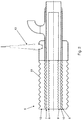
- Die Erfindung lässt verschiedene Ausführungsformen zu. Zur weiteren Verdeutlichung ihres Grundprinzips ist eine davon in der Zeichnung dargestellt und wird nachfolgend beschrieben. Diese zeigt in
- Fig. 1
- eine Prinzipdarstellung einer erfindungsgemäßen Einrichtung mit einer Leitung für Treibstoff;
- Fig. 2
- eine perspektivische, teilweise geschnittene Darstellung eines Leitungsabschnittes der in
Figur 1 gezeigten Leitung; - Fig. 3
- einen Stand-By-Betrieb der Einrichtung;
- Fig. 4
- einen Entnahme-Betrieb der Einrichtung:
- Fig. 5
- einen Stand-By-Betrieb einer Variante der Einrichtung;
- Fig. 6
- einen Entnahme -Betrieb der in
Figur 5 gezeigten Einrichtung. - Eine erfindungsgemäße, zum Betanken von verschiedenen Fahrzeugen und Wasserfahrzeugen bestimmte Einrichtung 1 wird nachstehend anhand der
Figuren 1 bis 4 näher erläutert. Die Einrichtung 1 ermöglicht die Betankung verschiedener Kraftfahrzeuge 2 mit einem als Treibstoff dienenden verflüssigten Gas, insbesondere Flüssigerdgas (LNG). Hierzu hat die Einrichtung einen als oberirdischer Tank ausgeführten Speicherbehälter 3 für die Speicherung des verflüssigten Gases, dem eine nicht weiter dargestellte Kühleinrichtung zugeordnet ist, um das Gas durch Abkühlung auf einen geeigneten Temperaturbereich unterhalb von -160 °C zu verflüssigen. Zwischen einer jeweiligen als Zapfstelle ausgeführten Betankungseinrichtung 4, die in an sich bekannter Weise für die verschiedenen Kraftfahrzeugarten entsprechend ausgestattet ist, ist eine als Wellrohr ausgeführte Leitung 5 angeordnet. - Der konstruktive Aufbau der Leitung 5 wird anhand der
Figur 2 näher erläutert. Die Leitung 5 hat eine medienführende zentrale Rohrleitung 6 als Mediumrohr, durch welche der Treibstoff von dem Speicherbehälter 3 zu der jeweiligen Betankungseinrichtung 4 gefördert werden kann. Diese ist von zwei weiteren medienführenden Rohrleitungen 7, 8 konzentrisch eingeschlossen, sodass zwei medienführende Ringräume 9, 10 entstehen, deren Funktion nachfolgend noch mit Bezug zu denFiguren 3 und4 erläutert wird. Schließlich ist noch ein äußeres Mantelrohr 11 als Außenrohr vorgesehen, welches zwischen der Rohrleitung 8 und dem Mantelrohr 11 ein ringförmiges Isoliermaterial 12 einschließt, um so die Leitung 5 thermisch zu isolieren. Zudem sind die Rohrleitungen 6, 7, 8 und das Mantelrohr 11 als thermisch selbstkompensierende metallische Wellrohre ausgeführt. Die zentrale Rohrleitung 6 und die medienführenden Ringräume 9, 10 sind thermisch nicht gegeneinander isoliert. Indem die zentrale Rohrleitung 6 und die beiden medienführenden Ringräume 9, 10 lediglich durch die Wandfläche der jeweiligen Rohrleitungen 6, 7 getrennt, nicht jedoch thermisch isoliert sind, wird dem in den Ringräumen 9, 10 geführten Medium durch den in der zentralen Rohrleitung 6 geführten Treibstoff Wärme entzogen und dieses entsprechend gekühlt. Dabei bildet die koaxiale Trennwand zwischen den Rohrleitungen 6, 7, 8 aufgrund der Ausführung als Wellrohr eine optimale Tauscherfläche. Durch die konzentrische Bauform wird zugleich auch die thermische Isolierung gegenüber der Umgebung verbessert, indem lediglich eine einzige äußere Isolierung erforderlich ist. Zur Überprüfung ist dem äußeren Ringraum 10 zwischen dem Mantelrohr 11 und der Rohrleitung 8 eine Leckageüberwachungseinrichtung 13 zugeordnet und ermöglicht so die kontinuierliche Überwachung der Leitung auf mögliche Undichtigkeiten. - Zusätzlich zu der dem Transport des Treibstoffes dienenden zentralen Rohrleitung 6 ermöglichen die beiden separaten Ringräume 9, 10 zwischen den konzentrischen Leitungen 7, 8 zwei verschiedene Betriebszustände, die nachstehend mit Bezug auf die
Figuren 3 und4 näher erläutert werden. Zum einen zeigtFigur 3 einen "Stand-by-Betrieb", in dem kontinuierlich aus dem Speicherbehälter 3 Treibstoff entnommen wird und durch die zentrale Rohrleitung 6 bis zu einem Strömungsumkehrbereich 14 vor einem nicht gezeigten, verschlossenen Leitungsende in einen dem Speicherbehälter 3 abgewandten Leitungsabschnitt gefördert wird. Der Treibstoff wird dann in Pfeilrichtung 16 durch den inneren Ringraum 9 und zwei Leitungsanschlüsse 15 zurück in den Speicherbehälter 3 gefördert. Hierdurch ergibt sich eine kontinuierliche Strömung in der Leitung 5, durch die eine unerwünschte Erwärmung vermieden werden kann. - Zum anderen wird der äußere Ringraum 10 beim Betanken des Kraftfahrzeuges 2 zur Ableitung der aus einem Kraftfahrzeugtank verdrängten, auch als "Boil-Off-Gase" bezeichneten gasförmigen Volumina genutzt. Diese werden aus dem Kraftfahrzeugtank durch eine separate Einlassöffnung 18, den äußeren Ringraum 10 und eine Auslassöffnung 19 ohne eine Verbindung zu der zentralen Rohrleitung 6 in Pfeilrichtung 17 in den Speicherbehälter 3 geleitet, um diese dort erneut zu verflüssigen. Ein Austreten der gasförmigen Bestandteile aus dem Kraftfahrzeugtank in die Umgebung kann dadurch vermieden und unerwünschte Umweltbelastungen und Gefahren verhindert werden. In diesem Betriebsmodus erfolgt die Zuführung des Treibstoffes zugleich durch die zentrale Rohrleitung 6 als auch durch die Leitungsanschlüsse 15 und den ersten, inneren Ringraum 9. Auf diese Weise wird der Volumenstrom erhöht und der Tankvorgang dementsprechend verkürzt.
- Ergänzend wird in den
Figuren 5 und6 noch eine Variante der Einrichtung 1 gezeigt. Die Rohrleitung 6 ist dabei von lediglich einer medienführenden Rohrleitung 7 konzentrisch eingeschlossen, durch die ein medienführender Ringraum 9 entsteht. Ein äußeres Mantelrohr 11 bildet das Außenrohr, welches zwischen dem Ringraum 9 und dem Mantelrohr 11 ein ringförmiges Isoliermaterial 12 einschließt, um so die Rohrleitungen 6, 7 thermisch zu isolieren. Die zentrale Rohrleitung 6 und der medienführende Ringraum 9 sind thermisch nicht gegeneinander isoliert, sodass diese lediglich durch die Wandfläche der Rohrleitung 6 getrennt, nicht jedoch thermisch isoliert sind. - Wie durch Richtungspfeile verdeutlicht, ist sowohl in dem in
Figur 5 gezeigten Betriebsmodus der Zuführung von Flüssigerdgas als auch in dem inFigur 6 gezeigten Betriebsmodus der Absaugung von Boil-Off-Gasen BOG jeweils eine Zirkulation des in dem Speicherbehälter vorhandenen Flüssigerdgases durch die Rohrleitung 7 eingestellt. Auf diese Weise wird dem alternativ in der Rohrleitung 6 geführten Flüssigerdgas oder Boil-Off-Gas durch die Rohrleitung 7 Wärme entzogen und dieses entsprechend gekühlt, wobei die Boil-Off-Gase durch den Wärmeentzug verflüssigt werden können.BEZUGSZEICHENLISTE 1 Einrichtung 16 Pfeilrichtung 2 Kraftfahrzeug 17 Pfeilrichtung 3 Speicherbehälter 18 Einlassöffnung 4 Betankungseinrichtung 19 Auslassöffnung 5 Leitung 6 zentrale Rohrleitung 7 Rohrleitung 8 Rohrleitung 9 Ringraum 10 Ringraum 11 Mantelrohr 12 Isoliermaterial 13 Leckageüberwachungseinrichtung 14 Strömungsumkehrbereich 15 Leitungsanschluss
Claims (10)
- Einrichtung (1) zum Betanken von Kraftfahrzeugen (2) mit einem als Treibstoff dienenden Fluid aus verflüssigtem Gas, insbesondere verflüssigtem Erdgas, umfassend zumindest einen Speicherbehälter (3), eine Kühleinrichtung, zumindest eine Fördereinrichtung, durch die das Fluid aus dem Speicherbehälter (3) zumindest einer Betankungseinrichtung (4) für Kraftfahrzeuge (2) zuführbar ist, und zumindest eine der Zuführung des Fluids zu der Betankungseinrichtung (4) dienende Leitung (5), wobei die Leitung (5) eine medienführende zentrale Rohrleitung (6) als Mediumrohr sowie zumindest eine weitere medienführende, zu der zentralen Rohrleitung (6) konzentrisch angeordnete, mit der eingeschlossenen Rohrleitung (6) einen Ringraum (10) begrenzende äußere Rohrleitung (8) hat, wobei die zentrale Rohrleitung (6) sowie zumindest ein Ringraum (9, 10) der Zu- bzw. Rückführung des Fluids oder eines Gasstromes dient, und dass die äußere Rohrleitung (8) von einem Mantelrohr (11) umgeben ist, wobei das Mantelrohr (11) gegenüber der äußeren Rohrleitung (7) thermisch isoliert und die zentrale Rohrleitung (6) als metallisches Wellrohr derart ausgeführt ist, dass die zentrale Rohrleitung (6) und zumindest ein medienführender Ringraum (9, 10) gegeneinander nicht thermisch isoliert sind, dadurch gekennzeichnet, dass zwischen der zentralen Rohrleitung (6) und der äusseren Rohrleitung (8) eine weitere, den Ringraum in einen inneren Ringraum (9) und einen äusseren Ringraum (10) unterteilende Rohrleitung (7) angeordnet ist.
- Einrichtung (1) nach Anspruch 1, dadurch gekennzeichnet, dass die Rohrleitungen (6, 7, 8) und das Mantelrohr (11) jeweils als thermisch selbstkompensierende metallische Wellrohre ausgeführt sind.
- Einrichtung (1) nach den Ansprüchen 1 oder 2, dadurch gekennzeichnet, dass alle Rohrleitungen (6, 7, 8) und das Mantelrohr (11) koaxial zueinander angeordnet sind.
- Einrichtung (1) nach zumindest einem der vorhergehenden Ansprüche, dadurch gekennzeichnet, dass der äußere Ringraum (10) zur Ableitung der beim Betanken aus dem Kraftfahrzeugtank verdrängten Gasvolumina ausgeführt ist.
- Einrichtung (1) nach zumindest einem der vorhergehenden Ansprüche, dadurch gekennzeichnet, dass der äußere Ringraum (10) mit einer separaten Einlassöffnung (18) und einer separaten Auslassöffnung (19) ausgestattet ist.
- Einrichtung (1) nach zumindest einem der vorhergehenden Ansprüche, dadurch gekennzeichnet, dass die Einrichtung (1) einen Speicherbehälter (3) für Liquefied Natural Gas (LNG) aufweist und dass die Leitung (5) den Speicherbehälter (3) mit einer Betankungseinrichtung (4) verbindet.
- Einrichtung (1) nach zumindest einem der vorhergehenden Ansprüche, dadurch gekennzeichnet, dass in dem äußeren Ringraum (10) zwischen dem Mantelrohr (11) und der äußeren Rohrleitung (8) eine Leckageüberwachungseinrichtung (13) angeordnet ist.
- Einrichtung (1) nach zumindest einem der vorhergehenden Ansprüche, dadurch gekennzeichnet, dass in dem Ringraum (10) zwischen dem Mantelrohr (11) und der äußeren Rohrleitung (8) zumindest abschnittsweise ein thermisches Isoliermaterial (12) angeordnet ist.
- Einrichtung (1) nach zumindest einem der vorhergehenden Ansprüche, dadurch gekennzeichnet, dass die Leitung (5) selbstkompensierend ausgeführt ist.
- Einrichtung (1) nach zumindest einem der vorhergehenden Ansprüche, dadurch gekennzeichnet, dass die Leitung (5) zumindest abschnittsweise mit einer umfangsseitigen Verstärkung aus einer Armierung ausgestattet ist.
Priority Applications (1)
| Application Number | Priority Date | Filing Date | Title |
|---|---|---|---|
| PL16788660T PL3371506T3 (pl) | 2015-11-03 | 2016-10-26 | Urządzenie do tankowania pojazdów silnikowych gazem płynnym |
Applications Claiming Priority (2)
| Application Number | Priority Date | Filing Date | Title |
|---|---|---|---|
| DE102015118830.9A DE102015118830A1 (de) | 2015-11-03 | 2015-11-03 | Einrichtung zum Betanken von Kraftfahrzeugen mit verflüssigtem Gas |
| PCT/EP2016/075730 WO2017076706A1 (de) | 2015-11-03 | 2016-10-26 | Einrichtung zum betanken von kraftfahrzeugen mit verflüssigtem gas |
Publications (3)
| Publication Number | Publication Date |
|---|---|
| EP3371506A1 EP3371506A1 (de) | 2018-09-12 |
| EP3371506B1 true EP3371506B1 (de) | 2020-12-16 |
| EP3371506B8 EP3371506B8 (de) | 2021-03-17 |
Family
ID=57218872
Family Applications (1)
| Application Number | Title | Priority Date | Filing Date |
|---|---|---|---|
| EP16788660.5A Active EP3371506B8 (de) | 2015-11-03 | 2016-10-26 | Einrichtung zum betanken von kraftfahrzeugen mit verflüssigtem gas |
Country Status (5)
| Country | Link |
|---|---|
| US (1) | US10793417B2 (de) |
| EP (1) | EP3371506B8 (de) |
| DE (1) | DE102015118830A1 (de) |
| PL (1) | PL3371506T3 (de) |
| WO (1) | WO2017076706A1 (de) |
Families Citing this family (10)
| Publication number | Priority date | Publication date | Assignee | Title |
|---|---|---|---|---|
| US10773822B2 (en) * | 2016-05-29 | 2020-09-15 | Neoex Systems, Inc. | System and method for the transfer of cryogenic fluids |
| CN109899677A (zh) * | 2019-04-01 | 2019-06-18 | 太仓中科信息技术研究院 | 流速控制充气装置 |
| CN110578839A (zh) * | 2019-08-30 | 2019-12-17 | 北京航天动力研究所 | 一种用于输送液氢和液氧的真空绝热金属软管 |
| CN110848561B (zh) * | 2019-10-16 | 2024-06-28 | 北京航天试验技术研究所 | 一种液氢加注装置 |
| CN112432053A (zh) * | 2020-11-19 | 2021-03-02 | 深圳市凯丰实业发展有限公司 | 一种液氮储罐零排放系统装置 |
| US12011989B1 (en) | 2021-01-17 | 2024-06-18 | Neoex Systems, Inc. | Direct liquefaction for vehicle refueling |
| DE102021125688A1 (de) | 2021-10-04 | 2023-04-06 | Schmöle GmbH | Wärmetauscher und Verfahren zum Betanken eines Fahrzeuges |
| CN115325287B (zh) * | 2022-09-13 | 2024-07-30 | 西南石油大学 | 一种复合能源管道传输特性分析方法 |
| DE102022209941A1 (de) * | 2022-09-21 | 2024-03-21 | Bruker Switzerland Ag | Vorrichtung zum Transfer von flüssigem Helium, mit verringerten Transfer-Verlusten |
| DE102023200257B3 (de) * | 2023-01-13 | 2024-05-29 | Magna Energy Storage Systems Gesmbh | Kryotank umfassend eine Entnahmevorrichtung |
Family Cites Families (20)
| Publication number | Priority date | Publication date | Assignee | Title |
|---|---|---|---|---|
| DE721995C (de) * | 1940-11-05 | 1942-06-25 | Ruhrchemie Ag | Vorrichtung zum Tanken von unter Druck stehenden verfluessigten Gasen |
| DE1650060A1 (de) * | 1967-08-24 | 1970-08-27 | Kabel Metallwerke Ghh | Flexibles Leitungsrohr fuer den Transport von Fluessigkeiten oder Gasen |
| US4523548A (en) * | 1983-04-13 | 1985-06-18 | Michigan Consolidated Gas Company | Gaseous hydrocarbon fuel storage system and power plant for vehicles |
| DE3334770C2 (de) * | 1983-09-26 | 1994-03-31 | Kabelmetal Electro Gmbh | Leitungsrohr zur Fortleitung von tiefgekühlten Medien |
| US5076242A (en) * | 1990-07-18 | 1991-12-31 | Illinois Tool Works Inc. | Integral fuel line |
| US5353849A (en) * | 1992-05-27 | 1994-10-11 | Cryogenic Fuels Inc. | Apparatus for metering and transfer of cryogenic liquids |
| US5315831A (en) | 1993-01-22 | 1994-05-31 | Hydra-Rig, Incorporated | Liquid natural gas and compressed natural gas total fueling system |
| US5421160A (en) | 1993-03-23 | 1995-06-06 | Minnesota Valley Engineering, Inc. | No loss fueling system for natural gas powered vehicles |
| DE9310530U1 (de) * | 1993-07-15 | 1993-09-09 | Ke Rohrsysteme und Umwelttechnik GmbH, 30179 Hannover | Wärmeisoliertes Leitungsrohr |
| DE19501332A1 (de) | 1995-01-18 | 1996-07-25 | Alcatel Kabel Ag | Verfahren zum Kühlen eines koaxialen Rohrsystems |
| DE19546659C2 (de) | 1995-12-14 | 1999-01-07 | Messer Griesheim Gmbh | Einrichtung zum Betanken eines Fahrzeugs |
| AT413589B (de) * | 1998-04-09 | 2006-04-15 | Semperit Ag Holding | Flexibler kryogener schlauch |
| US6446672B1 (en) * | 1999-11-05 | 2002-09-10 | Wellstream, Inc. | Flexible pipe including vent passage and method of manufacturing same |
| US6513336B2 (en) * | 2000-11-14 | 2003-02-04 | Air Products And Chemicals, Inc. | Apparatus and method for transferring a cryogenic fluid |
| DE10117329A1 (de) | 2001-04-06 | 2002-10-10 | Linde Ag | Rohrbruchsicherung für eine vakuumisolierte Befüllleitung |
| US7946309B2 (en) * | 2005-04-26 | 2011-05-24 | Veeder-Root Company | Vacuum-actuated shear valve device, system, and method, particularly for use in service station environments |
| DE102004038460A1 (de) * | 2004-08-07 | 2006-03-16 | Messer France S.A. | Verfahren und Vorrichtung zum Befüllen eines Behälters mit Flüssiggas aus einem Vorratstank |
| DE202007018142U1 (de) | 2007-12-22 | 2009-03-05 | Weh, Erwin | Kupplung, insbesondere für LNG |
| DE102008060127A1 (de) * | 2008-12-03 | 2010-06-10 | Bayerische Motoren Werke Aktiengesellschaft | Anlage zum Betanken von Kraftfahrzeugen mit Wasserstoff |
| EP2466186A1 (de) | 2010-12-16 | 2012-06-20 | Air Products and Chemicals, Inc. | Verfahren zum Befüllen eines Gasspeicherbehälters |
-
2015
- 2015-11-03 DE DE102015118830.9A patent/DE102015118830A1/de not_active Withdrawn
-
2016
- 2016-10-26 US US15/771,093 patent/US10793417B2/en active Active
- 2016-10-26 PL PL16788660T patent/PL3371506T3/pl unknown
- 2016-10-26 EP EP16788660.5A patent/EP3371506B8/de active Active
- 2016-10-26 WO PCT/EP2016/075730 patent/WO2017076706A1/de not_active Ceased
Non-Patent Citations (1)
| Title |
|---|
| None * |
Also Published As
| Publication number | Publication date |
|---|---|
| DE102015118830A1 (de) | 2017-05-04 |
| PL3371506T3 (pl) | 2021-10-11 |
| EP3371506A1 (de) | 2018-09-12 |
| US20180312390A1 (en) | 2018-11-01 |
| WO2017076706A1 (de) | 2017-05-11 |
| EP3371506B8 (de) | 2021-03-17 |
| US10793417B2 (en) | 2020-10-06 |
Similar Documents
| Publication | Publication Date | Title |
|---|---|---|
| WO2017076706A1 (de) | Einrichtung zum betanken von kraftfahrzeugen mit verflüssigtem gas | |
| DE102010020476B4 (de) | Verwendung einer Vorrichtung zum Speichern, Umfüllen und/oder Transportieren von tiefkalt verflüssigtem brennbarem Gas in einem Fahrzeug | |
| EP0779468B1 (de) | Einrichtung zum Aufbewahren von tiefkaltem verflüssigtem Gas | |
| DE60220573T2 (de) | Pumpanlage und Verfahren zum Pumpen von Flüssigkeiten | |
| EP3708896B1 (de) | Gas-tank-system, verfahren zum betreiben des gas-tank-systems und zug mit gas-tank-system | |
| EP3027955A1 (de) | Tank | |
| DE102014209921B4 (de) | Druckbehälter für ein Fahrzeug | |
| DE102006025656B4 (de) | Vorrichtung zur Kraftstoffspeicherung und -förderung von kryogenem Kraftstoff | |
| DE102020117910B4 (de) | Druckgastank für ein Kraftfahrzeug | |
| EP3676529B1 (de) | Verfahren zum befüllen eines mobilen kältemitteltanks mit einem kryogenen kältemittel | |
| EP0574811B1 (de) | Verfahren zum Kaltfahren eines Speicherbehälters | |
| DE102017012125A1 (de) | Wärmeübertragungseinrichtung für die Kältebereitstellung in Kühlfahrzeugen, deren Kraftfahrzeugmotor mit LNG angetrieben wird | |
| DE102014209916A1 (de) | Hochdruckbehälter | |
| DE102017201045A1 (de) | Druckbehältersystem für ein Kraftfahrzeug | |
| DE202015009958U1 (de) | Einrichtung zum Betanken von Kraftfahrzeugen mit verflüssigtem Gas | |
| EP0779470A1 (de) | Einrichtung zum Betanken eines Fahrzeuges | |
| EP3708897A1 (de) | Gas-tank-system, verfahren zum betreiben des gas-tank-systems und zug mit gas-tank-system | |
| DE102019134474A1 (de) | Kraftstoffversorgungseinrichtung für kryogene Kraftstoffe | |
| DE102010010108B4 (de) | Verfahren zur Speicherung von und Speicher für Erdgas | |
| DE102018212117A1 (de) | Vorratstank, Kraftstofffördereinrichtung und Verfahren zur Regulierung des Druckes in einem Vorratstank | |
| DE102014209919A1 (de) | Kryodruckbehälter | |
| DE102023200257B3 (de) | Kryotank umfassend eine Entnahmevorrichtung | |
| DE19546617A1 (de) | Einrichtung zum Versorgen eines Verbrauchers mit Kryokraftstoff aus einem Kryotank | |
| DE102014209912A1 (de) | Drucktank für ein Fahrzeug | |
| EP4191120B1 (de) | Kryogen-speichersystem |
Legal Events
| Date | Code | Title | Description |
|---|---|---|---|
| STAA | Information on the status of an ep patent application or granted ep patent |
Free format text: STATUS: UNKNOWN |
|
| STAA | Information on the status of an ep patent application or granted ep patent |
Free format text: STATUS: THE INTERNATIONAL PUBLICATION HAS BEEN MADE |
|
| PUAI | Public reference made under article 153(3) epc to a published international application that has entered the european phase |
Free format text: ORIGINAL CODE: 0009012 |
|
| STAA | Information on the status of an ep patent application or granted ep patent |
Free format text: STATUS: REQUEST FOR EXAMINATION WAS MADE |
|
| 17P | Request for examination filed |
Effective date: 20180604 |
|
| AK | Designated contracting states |
Kind code of ref document: A1 Designated state(s): AL AT BE BG CH CY CZ DE DK EE ES FI FR GB GR HR HU IE IS IT LI LT LU LV MC MK MT NL NO PL PT RO RS SE SI SK SM TR |
|
| AX | Request for extension of the european patent |
Extension state: BA ME |
|
| DAV | Request for validation of the european patent (deleted) | ||
| DAX | Request for extension of the european patent (deleted) | ||
| GRAP | Despatch of communication of intention to grant a patent |
Free format text: ORIGINAL CODE: EPIDOSNIGR1 |
|
| STAA | Information on the status of an ep patent application or granted ep patent |
Free format text: STATUS: GRANT OF PATENT IS INTENDED |
|
| INTG | Intention to grant announced |
Effective date: 20200921 |
|
| GRAS | Grant fee paid |
Free format text: ORIGINAL CODE: EPIDOSNIGR3 |
|
| GRAA | (expected) grant |
Free format text: ORIGINAL CODE: 0009210 |
|
| STAA | Information on the status of an ep patent application or granted ep patent |
Free format text: STATUS: THE PATENT HAS BEEN GRANTED |
|
| AK | Designated contracting states |
Kind code of ref document: B1 Designated state(s): AL AT BE BG CH CY CZ DE DK EE ES FI FR GB GR HR HU IE IS IT LI LT LU LV MC MK MT NL NO PL PT RO RS SE SI SK SM TR |
|
| REG | Reference to a national code |
Ref country code: GB Ref legal event code: FG4D Free format text: NOT ENGLISH |
|
| REG | Reference to a national code |
Ref country code: DE Ref legal event code: R096 Ref document number: 502016012001 Country of ref document: DE |
|
| REG | Reference to a national code |
Ref country code: IE Ref legal event code: FG4D Free format text: LANGUAGE OF EP DOCUMENT: GERMAN |
|
| REG | Reference to a national code |
Ref country code: AT Ref legal event code: REF Ref document number: 1345917 Country of ref document: AT Kind code of ref document: T Effective date: 20210115 |
|
| RAP2 | Party data changed (patent owner data changed or rights of a patent transferred) |
Owner name: BRUGG ROHRSYSTEM AG |
|
| REG | Reference to a national code |
Ref country code: DE Ref legal event code: R082 Ref document number: 502016012001 Country of ref document: DE Representative=s name: PATENTANWALTSKANZLEI SCHEFFLER, DE Ref country code: DE Ref legal event code: R081 Ref document number: 502016012001 Country of ref document: DE Owner name: BRUGG ROHRSYSTEM AG, CH Free format text: FORMER OWNER: BRUGG ROHR AG HOLDING, BRUGG, CH |
|
| REG | Reference to a national code |
Ref country code: CH Ref legal event code: PK Free format text: BERICHTIGUNG B8 |
|
| REG | Reference to a national code |
Ref country code: NL Ref legal event code: FP |
|
| PG25 | Lapsed in a contracting state [announced via postgrant information from national office to epo] |
Ref country code: NO Free format text: LAPSE BECAUSE OF FAILURE TO SUBMIT A TRANSLATION OF THE DESCRIPTION OR TO PAY THE FEE WITHIN THE PRESCRIBED TIME-LIMIT Effective date: 20210316 Ref country code: RS Free format text: LAPSE BECAUSE OF FAILURE TO SUBMIT A TRANSLATION OF THE DESCRIPTION OR TO PAY THE FEE WITHIN THE PRESCRIBED TIME-LIMIT Effective date: 20201216 Ref country code: GR Free format text: LAPSE BECAUSE OF FAILURE TO SUBMIT A TRANSLATION OF THE DESCRIPTION OR TO PAY THE FEE WITHIN THE PRESCRIBED TIME-LIMIT Effective date: 20210317 Ref country code: FI Free format text: LAPSE BECAUSE OF FAILURE TO SUBMIT A TRANSLATION OF THE DESCRIPTION OR TO PAY THE FEE WITHIN THE PRESCRIBED TIME-LIMIT Effective date: 20201216 |
|
| PG25 | Lapsed in a contracting state [announced via postgrant information from national office to epo] |
Ref country code: BG Free format text: LAPSE BECAUSE OF FAILURE TO SUBMIT A TRANSLATION OF THE DESCRIPTION OR TO PAY THE FEE WITHIN THE PRESCRIBED TIME-LIMIT Effective date: 20210316 Ref country code: LV Free format text: LAPSE BECAUSE OF FAILURE TO SUBMIT A TRANSLATION OF THE DESCRIPTION OR TO PAY THE FEE WITHIN THE PRESCRIBED TIME-LIMIT Effective date: 20201216 Ref country code: SE Free format text: LAPSE BECAUSE OF FAILURE TO SUBMIT A TRANSLATION OF THE DESCRIPTION OR TO PAY THE FEE WITHIN THE PRESCRIBED TIME-LIMIT Effective date: 20201216 |
|
| PG25 | Lapsed in a contracting state [announced via postgrant information from national office to epo] |
Ref country code: HR Free format text: LAPSE BECAUSE OF FAILURE TO SUBMIT A TRANSLATION OF THE DESCRIPTION OR TO PAY THE FEE WITHIN THE PRESCRIBED TIME-LIMIT Effective date: 20201216 |
|
| REG | Reference to a national code |
Ref country code: LT Ref legal event code: MG9D |
|
| PG25 | Lapsed in a contracting state [announced via postgrant information from national office to epo] |
Ref country code: SM Free format text: LAPSE BECAUSE OF FAILURE TO SUBMIT A TRANSLATION OF THE DESCRIPTION OR TO PAY THE FEE WITHIN THE PRESCRIBED TIME-LIMIT Effective date: 20201216 Ref country code: LT Free format text: LAPSE BECAUSE OF FAILURE TO SUBMIT A TRANSLATION OF THE DESCRIPTION OR TO PAY THE FEE WITHIN THE PRESCRIBED TIME-LIMIT Effective date: 20201216 Ref country code: EE Free format text: LAPSE BECAUSE OF FAILURE TO SUBMIT A TRANSLATION OF THE DESCRIPTION OR TO PAY THE FEE WITHIN THE PRESCRIBED TIME-LIMIT Effective date: 20201216 Ref country code: RO Free format text: LAPSE BECAUSE OF FAILURE TO SUBMIT A TRANSLATION OF THE DESCRIPTION OR TO PAY THE FEE WITHIN THE PRESCRIBED TIME-LIMIT Effective date: 20201216 Ref country code: PT Free format text: LAPSE BECAUSE OF FAILURE TO SUBMIT A TRANSLATION OF THE DESCRIPTION OR TO PAY THE FEE WITHIN THE PRESCRIBED TIME-LIMIT Effective date: 20210416 Ref country code: SK Free format text: LAPSE BECAUSE OF FAILURE TO SUBMIT A TRANSLATION OF THE DESCRIPTION OR TO PAY THE FEE WITHIN THE PRESCRIBED TIME-LIMIT Effective date: 20201216 |
|
| REG | Reference to a national code |
Ref country code: DE Ref legal event code: R097 Ref document number: 502016012001 Country of ref document: DE |
|
| PG25 | Lapsed in a contracting state [announced via postgrant information from national office to epo] |
Ref country code: IS Free format text: LAPSE BECAUSE OF FAILURE TO SUBMIT A TRANSLATION OF THE DESCRIPTION OR TO PAY THE FEE WITHIN THE PRESCRIBED TIME-LIMIT Effective date: 20210416 |
|
| PLBE | No opposition filed within time limit |
Free format text: ORIGINAL CODE: 0009261 |
|
| STAA | Information on the status of an ep patent application or granted ep patent |
Free format text: STATUS: NO OPPOSITION FILED WITHIN TIME LIMIT |
|
| PG25 | Lapsed in a contracting state [announced via postgrant information from national office to epo] |
Ref country code: AL Free format text: LAPSE BECAUSE OF FAILURE TO SUBMIT A TRANSLATION OF THE DESCRIPTION OR TO PAY THE FEE WITHIN THE PRESCRIBED TIME-LIMIT Effective date: 20201216 |
|
| 26N | No opposition filed |
Effective date: 20210917 |
|
| PG25 | Lapsed in a contracting state [announced via postgrant information from national office to epo] |
Ref country code: DK Free format text: LAPSE BECAUSE OF FAILURE TO SUBMIT A TRANSLATION OF THE DESCRIPTION OR TO PAY THE FEE WITHIN THE PRESCRIBED TIME-LIMIT Effective date: 20201216 |
|
| PG25 | Lapsed in a contracting state [announced via postgrant information from national office to epo] |
Ref country code: ES Free format text: LAPSE BECAUSE OF FAILURE TO SUBMIT A TRANSLATION OF THE DESCRIPTION OR TO PAY THE FEE WITHIN THE PRESCRIBED TIME-LIMIT Effective date: 20201216 |
|
| PG25 | Lapsed in a contracting state [announced via postgrant information from national office to epo] |
Ref country code: SI Free format text: LAPSE BECAUSE OF FAILURE TO SUBMIT A TRANSLATION OF THE DESCRIPTION OR TO PAY THE FEE WITHIN THE PRESCRIBED TIME-LIMIT Effective date: 20201216 |
|
| PG25 | Lapsed in a contracting state [announced via postgrant information from national office to epo] |
Ref country code: IS Free format text: LAPSE BECAUSE OF FAILURE TO SUBMIT A TRANSLATION OF THE DESCRIPTION OR TO PAY THE FEE WITHIN THE PRESCRIBED TIME-LIMIT Effective date: 20210416 |
|
| REG | Reference to a national code |
Ref country code: BE Ref legal event code: MM Effective date: 20211031 |
|
| PG25 | Lapsed in a contracting state [announced via postgrant information from national office to epo] |
Ref country code: MC Free format text: LAPSE BECAUSE OF FAILURE TO SUBMIT A TRANSLATION OF THE DESCRIPTION OR TO PAY THE FEE WITHIN THE PRESCRIBED TIME-LIMIT Effective date: 20201216 |
|
| PG25 | Lapsed in a contracting state [announced via postgrant information from national office to epo] |
Ref country code: LU Free format text: LAPSE BECAUSE OF NON-PAYMENT OF DUE FEES Effective date: 20211026 Ref country code: BE Free format text: LAPSE BECAUSE OF NON-PAYMENT OF DUE FEES Effective date: 20211031 |
|
| PG25 | Lapsed in a contracting state [announced via postgrant information from national office to epo] |
Ref country code: IE Free format text: LAPSE BECAUSE OF NON-PAYMENT OF DUE FEES Effective date: 20211026 |
|
| REG | Reference to a national code |
Ref country code: AT Ref legal event code: MM01 Ref document number: 1345917 Country of ref document: AT Kind code of ref document: T Effective date: 20211026 |
|
| PG25 | Lapsed in a contracting state [announced via postgrant information from national office to epo] |
Ref country code: AT Free format text: LAPSE BECAUSE OF NON-PAYMENT OF DUE FEES Effective date: 20211026 |
|
| PG25 | Lapsed in a contracting state [announced via postgrant information from national office to epo] |
Ref country code: HU Free format text: LAPSE BECAUSE OF FAILURE TO SUBMIT A TRANSLATION OF THE DESCRIPTION OR TO PAY THE FEE WITHIN THE PRESCRIBED TIME-LIMIT; INVALID AB INITIO Effective date: 20161026 |
|
| PG25 | Lapsed in a contracting state [announced via postgrant information from national office to epo] |
Ref country code: CY Free format text: LAPSE BECAUSE OF FAILURE TO SUBMIT A TRANSLATION OF THE DESCRIPTION OR TO PAY THE FEE WITHIN THE PRESCRIBED TIME-LIMIT Effective date: 20201216 |
|
| REG | Reference to a national code |
Ref country code: DE Ref legal event code: R082 Ref document number: 502016012001 Country of ref document: DE Representative=s name: CREUTZBURG, TOM, DIPL.-ING., DE |
|
| P01 | Opt-out of the competence of the unified patent court (upc) registered |
Effective date: 20240116 |
|
| PG25 | Lapsed in a contracting state [announced via postgrant information from national office to epo] |
Ref country code: MK Free format text: LAPSE BECAUSE OF FAILURE TO SUBMIT A TRANSLATION OF THE DESCRIPTION OR TO PAY THE FEE WITHIN THE PRESCRIBED TIME-LIMIT Effective date: 20201216 |
|
| PG25 | Lapsed in a contracting state [announced via postgrant information from national office to epo] |
Ref country code: MT Free format text: LAPSE BECAUSE OF FAILURE TO SUBMIT A TRANSLATION OF THE DESCRIPTION OR TO PAY THE FEE WITHIN THE PRESCRIBED TIME-LIMIT Effective date: 20201216 |
|
| PGFP | Annual fee paid to national office [announced via postgrant information from national office to epo] |
Ref country code: PL Payment date: 20250926 Year of fee payment: 10 |
|
| PGFP | Annual fee paid to national office [announced via postgrant information from national office to epo] |
Ref country code: CZ Payment date: 20250926 Year of fee payment: 10 |
|
| REG | Reference to a national code |
Ref country code: CH Ref legal event code: U11 Free format text: ST27 STATUS EVENT CODE: U-0-0-U10-U11 (AS PROVIDED BY THE NATIONAL OFFICE) Effective date: 20251101 |
|
| PGFP | Annual fee paid to national office [announced via postgrant information from national office to epo] |
Ref country code: NL Payment date: 20251024 Year of fee payment: 10 |
|
| PG25 | Lapsed in a contracting state [announced via postgrant information from national office to epo] |
Ref country code: TR Free format text: LAPSE BECAUSE OF FAILURE TO SUBMIT A TRANSLATION OF THE DESCRIPTION OR TO PAY THE FEE WITHIN THE PRESCRIBED TIME-LIMIT Effective date: 20201216 |
|
| PGFP | Annual fee paid to national office [announced via postgrant information from national office to epo] |
Ref country code: DE Payment date: 20251030 Year of fee payment: 10 |
|
| PGFP | Annual fee paid to national office [announced via postgrant information from national office to epo] |
Ref country code: GB Payment date: 20251024 Year of fee payment: 10 |
|
| PGFP | Annual fee paid to national office [announced via postgrant information from national office to epo] |
Ref country code: IT Payment date: 20251030 Year of fee payment: 10 |
|
| PGFP | Annual fee paid to national office [announced via postgrant information from national office to epo] |
Ref country code: FR Payment date: 20251024 Year of fee payment: 10 |
|
| PGFP | Annual fee paid to national office [announced via postgrant information from national office to epo] |
Ref country code: CH Payment date: 20251101 Year of fee payment: 10 |