EP3370496B1 - A sieve and a device for picking stones from soil - Google Patents
A sieve and a device for picking stones from soil Download PDFInfo
- Publication number
- EP3370496B1 EP3370496B1 EP16797731.3A EP16797731A EP3370496B1 EP 3370496 B1 EP3370496 B1 EP 3370496B1 EP 16797731 A EP16797731 A EP 16797731A EP 3370496 B1 EP3370496 B1 EP 3370496B1
- Authority
- EP
- European Patent Office
- Prior art keywords
- bars
- sieve
- bar
- soil
- stones
- Prior art date
- Legal status (The legal status is an assumption and is not a legal conclusion. Google has not performed a legal analysis and makes no representation as to the accuracy of the status listed.)
- Active
Links
Images


Classifications
-
- A—HUMAN NECESSITIES
- A01—AGRICULTURE; FORESTRY; ANIMAL HUSBANDRY; HUNTING; TRAPPING; FISHING
- A01B—SOIL WORKING IN AGRICULTURE OR FORESTRY; PARTS, DETAILS, OR ACCESSORIES OF AGRICULTURAL MACHINES OR IMPLEMENTS, IN GENERAL
- A01B43/00—Gatherers for removing stones, undesirable roots or the like from the soil, e.g. tractor-drawn rakes
Definitions
- the present invention relates to the field of agriculture. More specifically, the present invention relates in a first aspect to a sieve for picking stones from soil.
- the present invention relates to a stone picking device for picking and colleting stones from soil.
- the present invention relates to a use of a sieve according to the first aspect of the present invention or of a device according to the second aspect of the present invention for stone picking stones from soil
- the present invention relates to method for stone picking stones from soil.
- Such conditioning may relate to ploughing, cultivation, harrowing etc.
- the conditioning serves the purpose of aerating the soil, destroying the rooting of weed and to burry residues of last year's crops.
- Conditionings like ploughing, cultivation and harrowing are typically performed by towing an agricultural tool or implement behind a tractor.
- Stones in soil likewise pose a problem in the field of gardening, horticulture, road construction, beach cleaning and other material handling.
- Some of these tools comprise a sieve which comprises a number of parallel bars.
- the sieve is intended for moving through the soil, e.g. by being towed by a tractor.
- the distance between adjacent bars determines the coarseness of the sieve and hence determines the threshold between stone sizes to be picked or collected and sizes of material to be left in the soil.
- US 540 148 discloses an apparatus in the form of a combined stone gatherer and potato digger.
- This apparatus comprises a number of bars arranged in parallel on two crossbars in a frame. Each bar is having an L-shaped cross-section.
- the bars are not grouped in pairs by providing a connection of the lower ends of each of two adjacent bars nor does this document disclose that the smallest distance between two adjacent bars is only being present at a leading surface thereof. Thereby, stones are prone to get stuck in the gap between adjacent bars at the lower ends thereof.
- the present invention relates in a first aspect to a sieve for stone picking stones from soil, said sieve in the orientation intended for use comprising:
- the present invention relates in a second aspect to a stone picking device for picking and colleting stones from soil; wherein said stone picking device comprises a frame; wherein said frame comprises a sieve according to any of the preceding claims; wherein said frame comprises stone conveying means for removing stones from an area located at an upper end of said bars of said sieve.
- the present invention relates to a use of a sieve according to the first aspect of the present invention or of a device according to the second aspect of the present invention for stone picking stones from soil.
- the present invention relates to a method for stone picking stones from soil, wherein said method comprises:
- the present invention in its various aspects provides for enhanced stone picking efficiency. This result is brought about by virtue of the special design of the individual bars of the sieve which to a large extent avoids the clogging of stones between individual bars of the sieve.
- the present invention relates to a sieve for stone picking stones from soil, said sieve in the orientation intended for use comprising:
- the term "the geometry of the bars and the sieve is configured in such a way that the smallest distance between said two adjacent bars is being present at the leading surface of said two adjacent bars” preferably is to be interpreted in such a way that when comparing the distance between two adjacent bars, at the leading surface thereof and at a trailing surface thereof, respectively, the measurement is performed at an equal longitudinal position of the two adjacent bars.
- one or more of said bars are exhibiting a concave curvature in the lengthwise direction along the leading surface of said bars.
- one or more of said bars are exhibiting a convex curvature in the lengthwise direction along the trailing surface of said bars. Such curvatures will provide for improved flow of stones, being picked up, along the bars.
- the number of bars is 4 - 210 bars, such a 10 - 200 bars, for example 20 - 190 bars, such as 30 - 180 bars, for example 40 - 170 bars, such as 50 - 160 bars, for example 60 - 150 bars, such as 70 - 140 bars, such as 80 - 130 bars, e.g. 90 - 120 bars or 100 - 110 bars.
- 4 - 210 bars such a 10 - 200 bars, for example 20 - 190 bars, such as 30 - 180 bars, for example 40 - 170 bars, such as 50 - 160 bars, for example 60 - 150 bars, such as 70 - 140 bars, such as 80 - 130 bars, e.g. 90 - 120 bars or 100 - 110 bars.
- said bars are being grouped in pairs in such a way that the lower ends of two adjacent bars are being connected to each other via an end part so as to form a U-shape end of said two adjacent bars. Connecting the bars in pairs at a lower end thereof provides for enhanced strength of the sieve in a situation where the lower ends are being moved through soil.
- said bars are being reinforced by being connected to a bracket.
- said bracket is mounted on a trailing surface of said bars. Connecting the bars to a bracket provides for enhanced strength of the sieve.
- said bars are being parallel arranged on said sieve.
- said bars are having a longest extension of 0.5 - 2.0 m, such as 0.6 - 1.9 m, for example 0.7 - 1.8 m, e.g. 0.8 - 1.7 m, for example 0.9 - 1.6 m, such as 1.0 - 1.5 m, for example 1.1 - 1.4 m or 1.2 - 1.3 m.
- the thickness of the bars, in a transverse direction relative to the intended direction of movement is 10 - 65 mm, such as 15 - 60 mm, for example 20 - 55 mm, e.g. 25 - 50 mm, such as 30 - 45 mm or 35 - 40 mm. These dimensions secure sufficient strength of the sieve.
- the mutual distance d between a bar and its adjacent bar, in respect of one or more of said bars, preferably in respect of all said bars, measured either at the leading surface or at the trailing surface, varies along the length of said bar.
- the mutual distance d between a bar and its adjacent bar varies along the length of said bar so as to increase when going from a lower end of said bar to an upper end of said bar; or so as to decrease when going from a lower end of said bar to an upper end of said bar.
- the cross section of said bar(s) is defining the shape of an isosceles trapezoid having side legs of equal length, wherein the longest base of the isosceles trapezoid is forming the leading surface of the bar and wherein the shortest base of the isosceles trapezoid is forming the trailing surface of the bar, thus extending between a first edge and a second edge of said trailing surface of said bar.
- the cross section of said bar(s) is defining the shape of a semicircle, wherein the diameter of the semicircle is forming the leading surface of the bar and wherein the curved perimeter of the semicircle is forming the trailing surface of the bar.
- the cross section of said bar(s) is defining the shape of a triangle, wherein one edge of the triangle is forming the leading surface of the bar, and wherein part of two edges and one vertex of the triangle is forming the trailing surface of the bar.
- said sieve comprises adjustment means for adjustment of the mutual distances d between two specific adjacent bars, preferably between any two adjacent bars.
- Such means for adjustment provides for an easy change of the threshold between size of stones to be picked up and size of stones to be left in the soil.
- the smallest distance between one edge of the leading surface of a specific bar and the nearest edge of the leading surface of an adjacent bar is 2 - 65 cm, such as 5 - 60 cm, for example 10 - 55 cm, such as 15 - 50 cm, for example 20 - 45 cm, such as 25 - 40 cm or 30 - 35 cm. This distance determines the threshold between size of stones to be picked up and size of stones to be left in the soil.
- the present invention relates to a stone picking device for picking and colleting stones from soil; wherein said stone picking device comprises a frame; wherein said frame comprises a sieve according to the first aspect of the present invention; wherein said frame comprises stone conveying means for removing stones from an area located at an upper end of said bars of said sieve.
- the stone picking device according to the second aspect of the present invention provides for easy collection of stones being picked up by the sieve.
- said stone conveying means being a conveyor belt.
- the stone picking device further comprising depth adjustment means for adjusting the depth of submersion into soil of the lower end of said bars of said sieve. This embodiment provides flexibility in the operation of the device.
- the stone picking device further comprising a hopper for storing the stones, removed by the stone conveying means.
- a hopper provides for easy disposal of the stones being collected from the soil.
- said frame comprises one or more wheels.
- said device is being a self-propelled device or wherein said device comprises coupling means for enabling coupling of the device to a towing tractor or the like.
- These embodiments provide for powered towing of the device.
- said device further comprising soil loosening and/or stone lifting means arranged in front of the sieve, relative to the intended direction of movement thereof.
- said soil loosening and/or stone lifting means comprises shears arranged on an axle and being configured to be able to rotate with the view to loosen soil and/or to lift from the soil, stones being present in the soil.
- Such soil loosening and/or stone lifting means provides for better capture of stones by the sieve.
- the present invention relates to a use of a sieve according to the first aspect of the present invention or of a device according to the second aspect of the present invention for stone picking stones from soil.
- the present invention relates to method for stone picking stones from soil, wherein said method comprises:
- the method is performed using a device according to the first aspect of the present invention.
- the speed of movement of the sieve is 1 - 14 km/h, such as 2 - 13 km/h, for example 3 - 12 km/h, for example 4 - 11 km/h, such as 5 - 10 km/h, for example 6 - 9 km/h or 7 - 8 km/h.
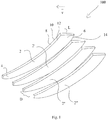
- Fig. 1 illustrates a perspective view of the bars of a sieve according to a first aspect of the present invention.
- the sieve 100 is for stone picking stones from soil.
- the sieve comprises in the orientation intended for use four bars 2,2',2",2"', wherein each bar is extending in a longitudinal direction between a lower end 4 configured to be at least partly submerged in soil, and an upper end 6.
- Each of the bars comprises a leading surface 8 extending a distance L from a first edge 10 to a second edge 12 of the leading surface of the bar. Furthermore, each bar comprises a trailing surface 14.
- the sieve 100 is characterized in that that in respect of any two specific adjacent bars 2,2',2",2"', the geometry of the bars and the sieve is configured in such a way that the smallest distance between said two adjacent bars is being present at the leading surface of said two adjacent bars.
- the lower part of the sieve 100 that is the lower part 4 of each bar is at least partly submerged into soil which is to be cleaned from stones and the sieve is moved through the soil in the direction defined by the leading surface 4 of the bars.
- This direction is in fig. 1 indicated by the velocity vector v.
- each bar 2,2',2",2"' is wedged and that the leading surface 4 is having a larger extension in a transverse direction, relative to the intended direction of movement of the sieve at the leading surface thereof, compared to the trailing surface of the bars. In this way, the smallest distance D between any two adjacent bars is being present at the leading surface of said two adjacent bars.
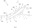
- Fig. 2 is a plan view illustrating the working mode of the sieve 100 according to the first aspect of the present invention.
- a sieve 100 comprising a number of individual bars 2,2',2",2" arranged parallel to each other (only one bar is visible in the side view of fig. 2 ) is moved through the soil 400 containing stones 300, sand, gravel and debris at velocity v in such a way that a lover end 4 of each bar 2,2',2",2"' is submerged into the soil.
- the "mesh size" of the sieve can be determined.
- the movement of the sieve 100 may be used for stone picking of stones in soil with the view to remove any stones having a size larger than a predetermined threshold size.
- fig. 2 In fig. 2 is shown that three stones 300 have been picked by the sieve 100 and is in the process of being moved to the upper part 6 of the bars and subsequently being moved backwards in order to exit the sieve upon which they will fall by the action of gravity. At this point the stones 300 may be picked up, e.g. by a conveyor belt and brought to a preliminary storage facility, such as a hopper in the vicinity of the sieve.
- a preliminary storage facility such as a hopper in the vicinity of the sieve.
- Fig. 3 is a top view of one embodiment of the sieve.
- Fig. 3 shows the sieve 100 comprising six bars 2,2',2",2"'. Each bar comprises a lower end 4 and an upper end 6. The leading surface 8 of each bar comprises a first edge 10 and a second edge 12.
- the smallest distance D between any two adjacent bars 2',2" is present between a first edge 10 of the leading surface 4 of one bar 2' and a second edge 12 of the leading surface of the adjacent bar 2".
- a bracket 18 is provided for reinforcing the sieve and for holding together the individual bars 2,2',2",2"' making up the sieve.
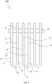
- Fig. 4 shows an alternative embodiment of the embodiment shown in fig. 3 .
- Fig 4 shows the sieve 100 comprising six bars 2,2',2",2"'. Each bar comprises a lower end 4 and an upper end 6.
- Fig. 4 shows that in respect of two adjacent bars of the sieve, these two bars are being connected to each other by an end part 16.
- the bars are being grouped in pairs in such a way that the lower end 4 of two adjacent bars 2,2' and 2", 2'" respectively are being connected to each other so as to form a U-shape end of said two adjacent bars.
- Fig 5a, 5b and 5c illustrate various geometries of preferred cross-sections 20 of the bars 2,2',2",2"' of the sieve 100 according to the first aspect of the present invention.
- Fig 5a shows a cross-section of the bars 2,2',2",2"' of a sieve comprising four bars.
- the bars 2,2',2",2"' are each having a cross-section with the geometry of a an isosceles trapezoid.
- the trapezoid is having side legs 22 of equal length; the longest base 24 of the isosceles trapezoid is forming the leading surface 8 of the bar and the shortest base 26 of the isosceles trapezoid is forming the trailing surface 14 of the bar, thus extending between a first edge 28 and a second edge 30 of said trailing surface of that bar.
- Fig 5b shows a cross-section of the bars 2,2',2",2"' of a sieve comprising four bars.
- the bars 2,2',2",2"' are each having a cross-section with the geometry of a triangle, wherein one edge 36 of the triangle is forming the leading surface 8 of the bar, and wherein part of two edges 38 and one vertex 40 of the triangle is forming the trailing surface 14 of the bar.
- Fig 5c shows a cross-section of the bars 2,2',2",2"' of a sieve comprising four bars.
- the bars 2,2',2",2"' are each having a cross-section with the geometry of a semicircle, The diameter 32 of the semicircle is forming the leading surface 8 of the bar and wherein the curved perimeter 34 of the semicircle is forming the trailing surface 14 of the bar.
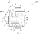
- Fig. 6 is a schematic illustration showing a top view of a stone picking device 200.
- the stone picking device 200 comprises a frame 42.
- the frame comprises a sieve 100.
- the sieve 100 is arranged on the frame 42 in such a way that a lower end 4 of the bars of the sieve is located relatively low and forward compared to the upper end 6 of the bars of the sieve.
- the frame comprises stone conveying means 44 in the form of a conveyor belt for removing stones from an area located at an upper end 6 of said bars of said sieve.
- the conveyor belt is arranged immediately below an upper end 6 of the bars 2,2' of the sieve 100.
- the stones conveyed by the conveying means 44 are conveyed to a hopper 48 for storing the stones removed by the stone conveying means.
- the frame is suspended by wheels 50 and the frame comprises coupling means 52 for allowing the device to be towed by a tractor or the like.
- fig 6 shows that the device 200 comprises soil loosening and/or stone lifting means 54 arranged in front of the sieve 100, relative to the intended direction of movement thereof.
- the soil loosening and/or stone lifting means 54 comprises shears 56 arranged on an axle 58.
- the axle 58 is being configured to be able to rotate with the view to loosen soil and/or to lift from the soil, stones being present in the soil.
- the device 200 is intended to be towed behind the tractor in the direction of movement defined by velocity vector v.
- the soil loosening and/or stone lifting means 54 arranged in front of the sieve 100 allows loosening of the soil and the stones. Subsequently, the stones being too large to fall and passing the space between two adjacent bars 2,2' of the sieve 100 will be lifted by the bars of the sieve and end up on the conveyor belt 44, whereafter they will be transported to the hopper 48.
- the stones, sand, gravel and debris having sizes enabling passage through the space between two adjacent bars 2,2' of the sieve 100 will pass these.
- the device 200 allows for easy and efficient stone picking from soil without the disadvantage of clogging the sieve of the device.
Landscapes
- Life Sciences & Earth Sciences (AREA)
- Engineering & Computer Science (AREA)
- Mechanical Engineering (AREA)
- Soil Sciences (AREA)
- Environmental Sciences (AREA)
- Combined Means For Separation Of Solids (AREA)
Priority Applications (1)
| Application Number | Priority Date | Filing Date | Title |
|---|---|---|---|
| PL16797731T PL3370496T3 (pl) | 2015-11-07 | 2016-11-04 | Sito i urządzenie do wybierania kamieni z gleby |
Applications Claiming Priority (2)
| Application Number | Priority Date | Filing Date | Title |
|---|---|---|---|
| DKPA201500699A DK178763B1 (en) | 2015-11-07 | 2015-11-07 | A sieve and a device for stone picking stones from soil |
| PCT/DK2016/050355 WO2017076415A1 (en) | 2015-11-07 | 2016-11-04 | A sieve and a device for picking stones from soil |
Publications (2)
| Publication Number | Publication Date |
|---|---|
| EP3370496A1 EP3370496A1 (en) | 2018-09-12 |
| EP3370496B1 true EP3370496B1 (en) | 2020-04-22 |
Family
ID=57345633
Family Applications (1)
| Application Number | Title | Priority Date | Filing Date |
|---|---|---|---|
| EP16797731.3A Active EP3370496B1 (en) | 2015-11-07 | 2016-11-04 | A sieve and a device for picking stones from soil |
Country Status (5)
| Country | Link |
|---|---|
| US (1) | US20180325008A1 (pl) |
| EP (1) | EP3370496B1 (pl) |
| DK (1) | DK178763B1 (pl) |
| PL (1) | PL3370496T3 (pl) |
| WO (1) | WO2017076415A1 (pl) |
Cited By (1)
| Publication number | Priority date | Publication date | Assignee | Title |
|---|---|---|---|---|
| DE102021114309A1 (de) | 2021-06-02 | 2022-12-08 | Markus Lembeck | Separiervorrichtung für Sammelmaschine sowie Verfahren |
Families Citing this family (2)
| Publication number | Priority date | Publication date | Assignee | Title |
|---|---|---|---|---|
| US10737297B2 (en) * | 2017-08-21 | 2020-08-11 | Cnh Industrial America Llc | Stone sieve apparatus |
| CN116137976B (zh) * | 2022-08-20 | 2025-01-21 | 博雅达勘测规划设计集团有限公司 | 耕作层的剥离和回覆装置及方法 |
Family Cites Families (21)
| Publication number | Priority date | Publication date | Assignee | Title |
|---|---|---|---|---|
| US540148A (en) * | 1895-05-28 | Potato-digger | ||
| US511550A (en) * | 1893-12-26 | Potato-digger | ||
| US1243327A (en) * | 1916-11-13 | 1917-10-16 | Frank A Martinez | Stone-rake. |
| US1452697A (en) * | 1919-11-21 | 1923-04-24 | John E Mullen | Agricultural machine |
| US1442979A (en) * | 1921-05-02 | 1923-01-23 | Ford W Shaw | Stone-gathering machine |
| US2484437A (en) * | 1946-02-16 | 1949-10-11 | Blair Mfg Company | Golf ball collector |
| US2852082A (en) * | 1955-03-29 | 1958-09-16 | Bruce H Petersen | Mechanical rock picker |
| US2827969A (en) * | 1955-06-06 | 1958-03-25 | Anthony J Mcpherson | Rock pickup and dumping device |
| US2888082A (en) * | 1955-11-23 | 1959-05-26 | Caldwell Kenneth | Stone picker rake |
| US3055128A (en) * | 1959-04-13 | 1962-09-25 | Floyd B Edwards | Points for digging buckets |
| US3200891A (en) * | 1963-04-16 | 1965-08-17 | John W Marron | Bulldozer attachment |
| US3356158A (en) * | 1965-06-01 | 1967-12-05 | Lloyd C Deaver | Stone pickers |
| CA985912A (en) * | 1973-11-16 | 1976-03-23 | Clifford A. Ranger | Rock and root picker |
| US4050518A (en) * | 1976-07-01 | 1977-09-27 | Gilmour Richard C | Beach cleaning apparatus |
| DE3538895A1 (de) * | 1985-11-02 | 1987-05-07 | Amazonen Werke Dreyer H | Zinken fuer eine bodenbearbeitungsmaschine |
| RU1782366C (ru) * | 1987-04-16 | 1992-12-23 | И.Г.Сафонов, В.И.Сафонов, А.И.Сафонов и М.И.Сафонова | Устройство дл сбора камней с пол |
| FR2656764A1 (fr) * | 1990-01-10 | 1991-07-12 | Camalet Thierry | Ramasseuse de pierres. |
| US5564506A (en) * | 1995-02-27 | 1996-10-15 | Farmers' Factory Company | Rock raking apparatus |
| US6092606A (en) * | 1998-02-19 | 2000-07-25 | Basler; Jeffrey L. | Stone gathering apparatus |
| US7066275B1 (en) * | 2003-10-10 | 2006-06-27 | Keigley Kevin V | Rock separator with beveled tines and removable grates |
| US8745903B1 (en) * | 2011-02-17 | 2014-06-10 | Brandon L. Ritter | Rock removal skid steer attachment |
-
2015
- 2015-11-07 DK DKPA201500699A patent/DK178763B1/en not_active IP Right Cessation
-
2016
- 2016-11-04 US US15/773,485 patent/US20180325008A1/en not_active Abandoned
- 2016-11-04 PL PL16797731T patent/PL3370496T3/pl unknown
- 2016-11-04 EP EP16797731.3A patent/EP3370496B1/en active Active
- 2016-11-04 WO PCT/DK2016/050355 patent/WO2017076415A1/en not_active Ceased
Non-Patent Citations (1)
| Title |
|---|
| None * |
Cited By (1)
| Publication number | Priority date | Publication date | Assignee | Title |
|---|---|---|---|---|
| DE102021114309A1 (de) | 2021-06-02 | 2022-12-08 | Markus Lembeck | Separiervorrichtung für Sammelmaschine sowie Verfahren |
Also Published As
| Publication number | Publication date |
|---|---|
| DK201500699A1 (en) | 2017-01-09 |
| DK178763B1 (en) | 2017-01-09 |
| US20180325008A1 (en) | 2018-11-15 |
| PL3370496T3 (pl) | 2021-02-08 |
| WO2017076415A1 (en) | 2017-05-11 |
| EP3370496A1 (en) | 2018-09-12 |
Similar Documents
| Publication | Publication Date | Title |
|---|---|---|
| CN100435613C (zh) | 曲轴抛动床式花生收获机 | |
| CN103918395B (zh) | 一种胡萝卜切缨收获机 | |
| CN103947366B (zh) | 一种西洋参切秧收获机 | |
| EP3370496B1 (en) | A sieve and a device for picking stones from soil | |
| WO2014196302A1 (ja) | 畝形成方法及び形成装置 | |
| KR102136607B1 (ko) | 땅속작물 수확기 | |
| CN103931335A (zh) | 一种胡萝卜夹持挖掘拍土切缨收获机 | |
| KR101782255B1 (ko) | 트랙터 견인식 대파 수확기 | |
| US5373904A (en) | Cultivator blade | |
| CN104380905B (zh) | 一种天麻收获机 | |
| CN212184166U (zh) | 一种田园收获机 | |
| US20100018730A1 (en) | Optimized scuffle hoe, multi-purpose garden tool | |
| KR20180072141A (ko) | 알뿌리 작물 수확기 | |
| KR20200065238A (ko) | 작물 모음장치가 구비된 땅속작물 수확기 | |
| CN2912223Y (zh) | 一种牵引式马铃薯联合收获机 | |
| US10470353B2 (en) | Rock collection and rock rowing device | |
| RU2579274C1 (ru) | Копатель-валкоукладчик для уборки клубней топинамбура | |
| NL8301302A (nl) | Inrichting voor het opbreken van de grond. | |
| JP6115984B2 (ja) | 農作業機 | |
| US8291562B2 (en) | Rake tine replacement tool | |
| CA2926833A1 (en) | Rock collection and rock rowing device | |
| KR102127285B1 (ko) | 지중 작물 수확기 | |
| GB2481646A (en) | Agricultural implement for filtering and grinding soil | |
| CN215835812U (zh) | 园林用石块收集装置 | |
| CN205378544U (zh) | 一种侧输出马铃薯收获机 |
Legal Events
| Date | Code | Title | Description |
|---|---|---|---|
| STAA | Information on the status of an ep patent application or granted ep patent |
Free format text: STATUS: UNKNOWN |
|
| STAA | Information on the status of an ep patent application or granted ep patent |
Free format text: STATUS: THE INTERNATIONAL PUBLICATION HAS BEEN MADE |
|
| PUAI | Public reference made under article 153(3) epc to a published international application that has entered the european phase |
Free format text: ORIGINAL CODE: 0009012 |
|
| STAA | Information on the status of an ep patent application or granted ep patent |
Free format text: STATUS: REQUEST FOR EXAMINATION WAS MADE |
|
| 17P | Request for examination filed |
Effective date: 20180607 |
|
| AK | Designated contracting states |
Kind code of ref document: A1 Designated state(s): AL AT BE BG CH CY CZ DE DK EE ES FI FR GB GR HR HU IE IS IT LI LT LU LV MC MK MT NL NO PL PT RO RS SE SI SK SM TR |
|
| AX | Request for extension of the european patent |
Extension state: BA ME |
|
| DAV | Request for validation of the european patent (deleted) | ||
| DAX | Request for extension of the european patent (deleted) | ||
| STAA | Information on the status of an ep patent application or granted ep patent |
Free format text: STATUS: EXAMINATION IS IN PROGRESS |
|
| 17Q | First examination report despatched |
Effective date: 20190424 |
|
| GRAP | Despatch of communication of intention to grant a patent |
Free format text: ORIGINAL CODE: EPIDOSNIGR1 |
|
| STAA | Information on the status of an ep patent application or granted ep patent |
Free format text: STATUS: GRANT OF PATENT IS INTENDED |
|
| INTG | Intention to grant announced |
Effective date: 20191114 |
|
| GRAS | Grant fee paid |
Free format text: ORIGINAL CODE: EPIDOSNIGR3 |
|
| GRAA | (expected) grant |
Free format text: ORIGINAL CODE: 0009210 |
|
| STAA | Information on the status of an ep patent application or granted ep patent |
Free format text: STATUS: THE PATENT HAS BEEN GRANTED |
|
| AK | Designated contracting states |
Kind code of ref document: B1 Designated state(s): AL AT BE BG CH CY CZ DE DK EE ES FI FR GB GR HR HU IE IS IT LI LT LU LV MC MK MT NL NO PL PT RO RS SE SI SK SM TR |
|
| REG | Reference to a national code |
Ref country code: CH Ref legal event code: EP |
|
| REG | Reference to a national code |
Ref country code: IE Ref legal event code: FG4D |
|
| REG | Reference to a national code |
Ref country code: DE Ref legal event code: R096 Ref document number: 602016034681 Country of ref document: DE |
|
| REG | Reference to a national code |
Ref country code: AT Ref legal event code: REF Ref document number: 1258817 Country of ref document: AT Kind code of ref document: T Effective date: 20200515 |
|
| REG | Reference to a national code |
Ref country code: LT Ref legal event code: MG4D |
|
| REG | Reference to a national code |
Ref country code: NL Ref legal event code: MP Effective date: 20200422 |
|
| PG25 | Lapsed in a contracting state [announced via postgrant information from national office to epo] |
Ref country code: PT Free format text: LAPSE BECAUSE OF FAILURE TO SUBMIT A TRANSLATION OF THE DESCRIPTION OR TO PAY THE FEE WITHIN THE PRESCRIBED TIME-LIMIT Effective date: 20200824 Ref country code: FI Free format text: LAPSE BECAUSE OF FAILURE TO SUBMIT A TRANSLATION OF THE DESCRIPTION OR TO PAY THE FEE WITHIN THE PRESCRIBED TIME-LIMIT Effective date: 20200422 Ref country code: LT Free format text: LAPSE BECAUSE OF FAILURE TO SUBMIT A TRANSLATION OF THE DESCRIPTION OR TO PAY THE FEE WITHIN THE PRESCRIBED TIME-LIMIT Effective date: 20200422 Ref country code: IS Free format text: LAPSE BECAUSE OF FAILURE TO SUBMIT A TRANSLATION OF THE DESCRIPTION OR TO PAY THE FEE WITHIN THE PRESCRIBED TIME-LIMIT Effective date: 20200822 Ref country code: SE Free format text: LAPSE BECAUSE OF FAILURE TO SUBMIT A TRANSLATION OF THE DESCRIPTION OR TO PAY THE FEE WITHIN THE PRESCRIBED TIME-LIMIT Effective date: 20200422 Ref country code: GR Free format text: LAPSE BECAUSE OF FAILURE TO SUBMIT A TRANSLATION OF THE DESCRIPTION OR TO PAY THE FEE WITHIN THE PRESCRIBED TIME-LIMIT Effective date: 20200723 Ref country code: NO Free format text: LAPSE BECAUSE OF FAILURE TO SUBMIT A TRANSLATION OF THE DESCRIPTION OR TO PAY THE FEE WITHIN THE PRESCRIBED TIME-LIMIT Effective date: 20200722 Ref country code: NL Free format text: LAPSE BECAUSE OF FAILURE TO SUBMIT A TRANSLATION OF THE DESCRIPTION OR TO PAY THE FEE WITHIN THE PRESCRIBED TIME-LIMIT Effective date: 20200422 |
|
| REG | Reference to a national code |
Ref country code: AT Ref legal event code: MK05 Ref document number: 1258817 Country of ref document: AT Kind code of ref document: T Effective date: 20200422 |
|
| PG25 | Lapsed in a contracting state [announced via postgrant information from national office to epo] |
Ref country code: HR Free format text: LAPSE BECAUSE OF FAILURE TO SUBMIT A TRANSLATION OF THE DESCRIPTION OR TO PAY THE FEE WITHIN THE PRESCRIBED TIME-LIMIT Effective date: 20200422 Ref country code: RS Free format text: LAPSE BECAUSE OF FAILURE TO SUBMIT A TRANSLATION OF THE DESCRIPTION OR TO PAY THE FEE WITHIN THE PRESCRIBED TIME-LIMIT Effective date: 20200422 Ref country code: LV Free format text: LAPSE BECAUSE OF FAILURE TO SUBMIT A TRANSLATION OF THE DESCRIPTION OR TO PAY THE FEE WITHIN THE PRESCRIBED TIME-LIMIT Effective date: 20200422 Ref country code: BG Free format text: LAPSE BECAUSE OF FAILURE TO SUBMIT A TRANSLATION OF THE DESCRIPTION OR TO PAY THE FEE WITHIN THE PRESCRIBED TIME-LIMIT Effective date: 20200722 |
|
| PG25 | Lapsed in a contracting state [announced via postgrant information from national office to epo] |
Ref country code: AL Free format text: LAPSE BECAUSE OF FAILURE TO SUBMIT A TRANSLATION OF THE DESCRIPTION OR TO PAY THE FEE WITHIN THE PRESCRIBED TIME-LIMIT Effective date: 20200422 |
|
| REG | Reference to a national code |
Ref country code: DE Ref legal event code: R097 Ref document number: 602016034681 Country of ref document: DE |
|
| PG25 | Lapsed in a contracting state [announced via postgrant information from national office to epo] |
Ref country code: ES Free format text: LAPSE BECAUSE OF FAILURE TO SUBMIT A TRANSLATION OF THE DESCRIPTION OR TO PAY THE FEE WITHIN THE PRESCRIBED TIME-LIMIT Effective date: 20200422 Ref country code: SM Free format text: LAPSE BECAUSE OF FAILURE TO SUBMIT A TRANSLATION OF THE DESCRIPTION OR TO PAY THE FEE WITHIN THE PRESCRIBED TIME-LIMIT Effective date: 20200422 Ref country code: EE Free format text: LAPSE BECAUSE OF FAILURE TO SUBMIT A TRANSLATION OF THE DESCRIPTION OR TO PAY THE FEE WITHIN THE PRESCRIBED TIME-LIMIT Effective date: 20200422 Ref country code: DK Free format text: LAPSE BECAUSE OF FAILURE TO SUBMIT A TRANSLATION OF THE DESCRIPTION OR TO PAY THE FEE WITHIN THE PRESCRIBED TIME-LIMIT Effective date: 20200422 Ref country code: IT Free format text: LAPSE BECAUSE OF FAILURE TO SUBMIT A TRANSLATION OF THE DESCRIPTION OR TO PAY THE FEE WITHIN THE PRESCRIBED TIME-LIMIT Effective date: 20200422 Ref country code: RO Free format text: LAPSE BECAUSE OF FAILURE TO SUBMIT A TRANSLATION OF THE DESCRIPTION OR TO PAY THE FEE WITHIN THE PRESCRIBED TIME-LIMIT Effective date: 20200422 Ref country code: CZ Free format text: LAPSE BECAUSE OF FAILURE TO SUBMIT A TRANSLATION OF THE DESCRIPTION OR TO PAY THE FEE WITHIN THE PRESCRIBED TIME-LIMIT Effective date: 20200422 Ref country code: AT Free format text: LAPSE BECAUSE OF FAILURE TO SUBMIT A TRANSLATION OF THE DESCRIPTION OR TO PAY THE FEE WITHIN THE PRESCRIBED TIME-LIMIT Effective date: 20200422 |
|
| PG25 | Lapsed in a contracting state [announced via postgrant information from national office to epo] |
Ref country code: SK Free format text: LAPSE BECAUSE OF FAILURE TO SUBMIT A TRANSLATION OF THE DESCRIPTION OR TO PAY THE FEE WITHIN THE PRESCRIBED TIME-LIMIT Effective date: 20200422 |
|
| PLBE | No opposition filed within time limit |
Free format text: ORIGINAL CODE: 0009261 |
|
| STAA | Information on the status of an ep patent application or granted ep patent |
Free format text: STATUS: NO OPPOSITION FILED WITHIN TIME LIMIT |
|
| 26N | No opposition filed |
Effective date: 20210125 |
|
| PG25 | Lapsed in a contracting state [announced via postgrant information from national office to epo] |
Ref country code: SI Free format text: LAPSE BECAUSE OF FAILURE TO SUBMIT A TRANSLATION OF THE DESCRIPTION OR TO PAY THE FEE WITHIN THE PRESCRIBED TIME-LIMIT Effective date: 20200422 |
|
| REG | Reference to a national code |
Ref country code: DE Ref legal event code: R082 Ref document number: 602016034681 Country of ref document: DE Representative=s name: KROHER STROBEL RECHTS- UND PATENTANWAELTE PART, DE |
|
| PG25 | Lapsed in a contracting state [announced via postgrant information from national office to epo] |
Ref country code: MC Free format text: LAPSE BECAUSE OF FAILURE TO SUBMIT A TRANSLATION OF THE DESCRIPTION OR TO PAY THE FEE WITHIN THE PRESCRIBED TIME-LIMIT Effective date: 20200422 |
|
| REG | Reference to a national code |
Ref country code: CH Ref legal event code: PL |
|
| PG25 | Lapsed in a contracting state [announced via postgrant information from national office to epo] |
Ref country code: LU Free format text: LAPSE BECAUSE OF NON-PAYMENT OF DUE FEES Effective date: 20201104 |
|
| REG | Reference to a national code |
Ref country code: BE Ref legal event code: MM Effective date: 20201130 |
|
| PG25 | Lapsed in a contracting state [announced via postgrant information from national office to epo] |
Ref country code: CH Free format text: LAPSE BECAUSE OF NON-PAYMENT OF DUE FEES Effective date: 20201130 Ref country code: LI Free format text: LAPSE BECAUSE OF NON-PAYMENT OF DUE FEES Effective date: 20201130 |
|
| PG25 | Lapsed in a contracting state [announced via postgrant information from national office to epo] |
Ref country code: IE Free format text: LAPSE BECAUSE OF NON-PAYMENT OF DUE FEES Effective date: 20201104 |
|
| PG25 | Lapsed in a contracting state [announced via postgrant information from national office to epo] |
Ref country code: TR Free format text: LAPSE BECAUSE OF FAILURE TO SUBMIT A TRANSLATION OF THE DESCRIPTION OR TO PAY THE FEE WITHIN THE PRESCRIBED TIME-LIMIT Effective date: 20200422 Ref country code: MT Free format text: LAPSE BECAUSE OF FAILURE TO SUBMIT A TRANSLATION OF THE DESCRIPTION OR TO PAY THE FEE WITHIN THE PRESCRIBED TIME-LIMIT Effective date: 20200422 Ref country code: CY Free format text: LAPSE BECAUSE OF FAILURE TO SUBMIT A TRANSLATION OF THE DESCRIPTION OR TO PAY THE FEE WITHIN THE PRESCRIBED TIME-LIMIT Effective date: 20200422 |
|
| PG25 | Lapsed in a contracting state [announced via postgrant information from national office to epo] |
Ref country code: MK Free format text: LAPSE BECAUSE OF FAILURE TO SUBMIT A TRANSLATION OF THE DESCRIPTION OR TO PAY THE FEE WITHIN THE PRESCRIBED TIME-LIMIT Effective date: 20200422 |
|
| PG25 | Lapsed in a contracting state [announced via postgrant information from national office to epo] |
Ref country code: BE Free format text: LAPSE BECAUSE OF NON-PAYMENT OF DUE FEES Effective date: 20201130 |
|
| PGFP | Annual fee paid to national office [announced via postgrant information from national office to epo] |
Ref country code: GB Payment date: 20231123 Year of fee payment: 8 |
|
| PGFP | Annual fee paid to national office [announced via postgrant information from national office to epo] |
Ref country code: FR Payment date: 20231127 Year of fee payment: 8 Ref country code: DE Payment date: 20231121 Year of fee payment: 8 |
|
| PGFP | Annual fee paid to national office [announced via postgrant information from national office to epo] |
Ref country code: PL Payment date: 20231023 Year of fee payment: 8 |
|
| REG | Reference to a national code |
Ref country code: DE Ref legal event code: R119 Ref document number: 602016034681 Country of ref document: DE |
|
| GBPC | Gb: european patent ceased through non-payment of renewal fee |
Effective date: 20241104 |
|
| PG25 | Lapsed in a contracting state [announced via postgrant information from national office to epo] |
Ref country code: DE Free format text: LAPSE BECAUSE OF NON-PAYMENT OF DUE FEES Effective date: 20250603 |
|
| PG25 | Lapsed in a contracting state [announced via postgrant information from national office to epo] |
Ref country code: GB Free format text: LAPSE BECAUSE OF NON-PAYMENT OF DUE FEES Effective date: 20241104 |
|
| PG25 | Lapsed in a contracting state [announced via postgrant information from national office to epo] |
Ref country code: FR Free format text: LAPSE BECAUSE OF NON-PAYMENT OF DUE FEES Effective date: 20241130 |