EP3370019B1 - Échangeur de chaleur - Google Patents
Échangeur de chaleur Download PDFInfo
- Publication number
- EP3370019B1 EP3370019B1 EP16858794.7A EP16858794A EP3370019B1 EP 3370019 B1 EP3370019 B1 EP 3370019B1 EP 16858794 A EP16858794 A EP 16858794A EP 3370019 B1 EP3370019 B1 EP 3370019B1
- Authority
- EP
- European Patent Office
- Prior art keywords
- heat exchange
- exchange part
- heat exchanger
- heat
- tube
- Prior art date
- Legal status (The legal status is an assumption and is not a legal conclusion. Google has not performed a legal analysis and makes no representation as to the accuracy of the status listed.)
- Active
Links
- 238000005452 bending Methods 0.000 claims description 8
- 239000012530 fluid Substances 0.000 claims description 2
- 238000010586 diagram Methods 0.000 description 8
- 238000005192 partition Methods 0.000 description 6
- XLYOFNOQVPJJNP-UHFFFAOYSA-N water Substances O XLYOFNOQVPJJNP-UHFFFAOYSA-N 0.000 description 2
- 238000004378 air conditioning Methods 0.000 description 1
- 230000015572 biosynthetic process Effects 0.000 description 1
- 238000010438 heat treatment Methods 0.000 description 1
- 239000003507 refrigerant Substances 0.000 description 1
- 238000005057 refrigeration Methods 0.000 description 1
- 238000003466 welding Methods 0.000 description 1
Images


Classifications
-
- F—MECHANICAL ENGINEERING; LIGHTING; HEATING; WEAPONS; BLASTING
- F28—HEAT EXCHANGE IN GENERAL
- F28D—HEAT-EXCHANGE APPARATUS, NOT PROVIDED FOR IN ANOTHER SUBCLASS, IN WHICH THE HEAT-EXCHANGE MEDIA DO NOT COME INTO DIRECT CONTACT
- F28D1/00—Heat-exchange apparatus having stationary conduit assemblies for one heat-exchange medium only, the media being in contact with different sides of the conduit wall, in which the other heat-exchange medium is a large body of fluid, e.g. domestic or motor car radiators
- F28D1/02—Heat-exchange apparatus having stationary conduit assemblies for one heat-exchange medium only, the media being in contact with different sides of the conduit wall, in which the other heat-exchange medium is a large body of fluid, e.g. domestic or motor car radiators with heat-exchange conduits immersed in the body of fluid
- F28D1/04—Heat-exchange apparatus having stationary conduit assemblies for one heat-exchange medium only, the media being in contact with different sides of the conduit wall, in which the other heat-exchange medium is a large body of fluid, e.g. domestic or motor car radiators with heat-exchange conduits immersed in the body of fluid with tubular conduits
- F28D1/047—Heat-exchange apparatus having stationary conduit assemblies for one heat-exchange medium only, the media being in contact with different sides of the conduit wall, in which the other heat-exchange medium is a large body of fluid, e.g. domestic or motor car radiators with heat-exchange conduits immersed in the body of fluid with tubular conduits the conduits being bent, e.g. in a serpentine or zig-zag
- F28D1/0477—Heat-exchange apparatus having stationary conduit assemblies for one heat-exchange medium only, the media being in contact with different sides of the conduit wall, in which the other heat-exchange medium is a large body of fluid, e.g. domestic or motor car radiators with heat-exchange conduits immersed in the body of fluid with tubular conduits the conduits being bent, e.g. in a serpentine or zig-zag the conduits being bent in a serpentine or zig-zag
- F28D1/0478—Heat-exchange apparatus having stationary conduit assemblies for one heat-exchange medium only, the media being in contact with different sides of the conduit wall, in which the other heat-exchange medium is a large body of fluid, e.g. domestic or motor car radiators with heat-exchange conduits immersed in the body of fluid with tubular conduits the conduits being bent, e.g. in a serpentine or zig-zag the conduits being bent in a serpentine or zig-zag the conduits having a non-circular cross-section
-
- F—MECHANICAL ENGINEERING; LIGHTING; HEATING; WEAPONS; BLASTING
- F28—HEAT EXCHANGE IN GENERAL
- F28F—DETAILS OF HEAT-EXCHANGE AND HEAT-TRANSFER APPARATUS, OF GENERAL APPLICATION
- F28F9/00—Casings; Header boxes; Auxiliary supports for elements; Auxiliary members within casings
- F28F9/02—Header boxes; End plates
- F28F9/0246—Arrangements for connecting header boxes with flow lines
-
- F—MECHANICAL ENGINEERING; LIGHTING; HEATING; WEAPONS; BLASTING
- F25—REFRIGERATION OR COOLING; COMBINED HEATING AND REFRIGERATION SYSTEMS; HEAT PUMP SYSTEMS; MANUFACTURE OR STORAGE OF ICE; LIQUEFACTION SOLIDIFICATION OF GASES
- F25B—REFRIGERATION MACHINES, PLANTS OR SYSTEMS; COMBINED HEATING AND REFRIGERATION SYSTEMS; HEAT PUMP SYSTEMS
- F25B39/00—Evaporators; Condensers
-
- F—MECHANICAL ENGINEERING; LIGHTING; HEATING; WEAPONS; BLASTING
- F28—HEAT EXCHANGE IN GENERAL
- F28D—HEAT-EXCHANGE APPARATUS, NOT PROVIDED FOR IN ANOTHER SUBCLASS, IN WHICH THE HEAT-EXCHANGE MEDIA DO NOT COME INTO DIRECT CONTACT
- F28D1/00—Heat-exchange apparatus having stationary conduit assemblies for one heat-exchange medium only, the media being in contact with different sides of the conduit wall, in which the other heat-exchange medium is a large body of fluid, e.g. domestic or motor car radiators
- F28D1/02—Heat-exchange apparatus having stationary conduit assemblies for one heat-exchange medium only, the media being in contact with different sides of the conduit wall, in which the other heat-exchange medium is a large body of fluid, e.g. domestic or motor car radiators with heat-exchange conduits immersed in the body of fluid
- F28D1/04—Heat-exchange apparatus having stationary conduit assemblies for one heat-exchange medium only, the media being in contact with different sides of the conduit wall, in which the other heat-exchange medium is a large body of fluid, e.g. domestic or motor car radiators with heat-exchange conduits immersed in the body of fluid with tubular conduits
- F28D1/047—Heat-exchange apparatus having stationary conduit assemblies for one heat-exchange medium only, the media being in contact with different sides of the conduit wall, in which the other heat-exchange medium is a large body of fluid, e.g. domestic or motor car radiators with heat-exchange conduits immersed in the body of fluid with tubular conduits the conduits being bent, e.g. in a serpentine or zig-zag
- F28D1/0475—Heat-exchange apparatus having stationary conduit assemblies for one heat-exchange medium only, the media being in contact with different sides of the conduit wall, in which the other heat-exchange medium is a large body of fluid, e.g. domestic or motor car radiators with heat-exchange conduits immersed in the body of fluid with tubular conduits the conduits being bent, e.g. in a serpentine or zig-zag the conduits having a single U-bend
- F28D1/0476—Heat-exchange apparatus having stationary conduit assemblies for one heat-exchange medium only, the media being in contact with different sides of the conduit wall, in which the other heat-exchange medium is a large body of fluid, e.g. domestic or motor car radiators with heat-exchange conduits immersed in the body of fluid with tubular conduits the conduits being bent, e.g. in a serpentine or zig-zag the conduits having a single U-bend the conduits having a non-circular cross-section
-
- F—MECHANICAL ENGINEERING; LIGHTING; HEATING; WEAPONS; BLASTING
- F28—HEAT EXCHANGE IN GENERAL
- F28F—DETAILS OF HEAT-EXCHANGE AND HEAT-TRANSFER APPARATUS, OF GENERAL APPLICATION
- F28F1/00—Tubular elements; Assemblies of tubular elements
- F28F1/02—Tubular elements of cross-section which is non-circular
- F28F1/025—Tubular elements of cross-section which is non-circular with variable shape, e.g. with modified tube ends, with different geometrical features
-
- F—MECHANICAL ENGINEERING; LIGHTING; HEATING; WEAPONS; BLASTING
- F28—HEAT EXCHANGE IN GENERAL
- F28D—HEAT-EXCHANGE APPARATUS, NOT PROVIDED FOR IN ANOTHER SUBCLASS, IN WHICH THE HEAT-EXCHANGE MEDIA DO NOT COME INTO DIRECT CONTACT
- F28D21/00—Heat-exchange apparatus not covered by any of the groups F28D1/00 - F28D20/00
- F28D2021/0019—Other heat exchangers for particular applications; Heat exchange systems not otherwise provided for
- F28D2021/0068—Other heat exchangers for particular applications; Heat exchange systems not otherwise provided for for refrigerant cycles
- F28D2021/0071—Evaporators
-
- F—MECHANICAL ENGINEERING; LIGHTING; HEATING; WEAPONS; BLASTING
- F28—HEAT EXCHANGE IN GENERAL
- F28D—HEAT-EXCHANGE APPARATUS, NOT PROVIDED FOR IN ANOTHER SUBCLASS, IN WHICH THE HEAT-EXCHANGE MEDIA DO NOT COME INTO DIRECT CONTACT
- F28D21/00—Heat-exchange apparatus not covered by any of the groups F28D1/00 - F28D20/00
- F28D2021/0019—Other heat exchangers for particular applications; Heat exchange systems not otherwise provided for
- F28D2021/008—Other heat exchangers for particular applications; Heat exchange systems not otherwise provided for for vehicles
- F28D2021/0085—Evaporators
-
- F—MECHANICAL ENGINEERING; LIGHTING; HEATING; WEAPONS; BLASTING
- F28—HEAT EXCHANGE IN GENERAL
- F28F—DETAILS OF HEAT-EXCHANGE AND HEAT-TRANSFER APPARATUS, OF GENERAL APPLICATION
- F28F2260/00—Heat exchangers or heat exchange elements having special size, e.g. microstructures
- F28F2260/02—Heat exchangers or heat exchange elements having special size, e.g. microstructures having microchannels
Definitions
- the present invention relates to a heat exchanger.
- Heat exchangers comprising two manifolds arranged on the same side are disclosed in CN-A-103245132 , JP-A-2010169289 and EP-A-1762808 .
- EP-A-1762808 discloses a heat exchanger according to the preamble of claim 1.
- An object of an embodiment of the present invention is to provide a heat exchanger, such that manifolds are arranged on the same side, to save connecting pipelines.
- An embodiment of the present invention provides a heat exchanger according to claim 1.
- the second end deviates from a center line of the second heat exchange part by curving, and the first end and the second end deviate in opposite directions.
- the first heat exchange part and the second heat exchange part are arranged in a first direction, and extend in a second direction which is substantially perpendicular to the first direction, and the first end deviates from the center line of the first heat exchange part in a third direction which is substantially perpendicular to the first direction and the second direction.
- the first heat exchange part and the second heat exchange part are arranged in a first direction, and extend in a second direction which is substantially perpendicular to the first direction, the first end deviates from the center line of the first heat exchange part in a third direction which is substantially perpendicular to the first direction and the second direction, and the second end deviates from the center line of the second heat exchange part in a third direction which is substantially perpendicular to the first direction and the second direction.
- each heat exchange tube also has a plurality of third heat exchange parts disposed between the first heat exchange part and the second heat exchange part, and the first heat exchange part, the second heat exchange part and the third heat exchange parts are substantially parallel.
- each heat exchange tube also has a plurality of connecting parts connecting adjacent heat exchange parts amongst the first heat exchange part, the third heat exchange parts and the second heat exchange part, with at least one of the connecting parts being formed by bending, or being a U-shaped tube.
- the heat exchanger further comprises: a fin, disposed between the first heat exchange part and the second heat exchange part.
- the heat exchanger further comprises: a fin, disposed between adjacent heat exchange parts amongst the first heat exchange part, the third heat exchange parts and the second heat exchange part.
- the first end of each heat exchange tube is inclined relative to the first heat exchange part.
- the first end of each heat exchange tube is inclined relative to the first heat exchange part, and the second end of each heat exchange tube is inclined relative to the second heat exchange part.
- the first end deviates from the center line of the first heat exchange part by curving substantially in a plane defined by the second direction and the third direction.
- the first end deviates from the center line of the first heat exchange part by curving substantially in a plane defined by the second direction and the third direction
- the second end deviates from the center line of the second heat exchange part by curving substantially in the plane defined by the second direction and the third direction
- the first end and the first heat exchange part of each heat exchange tube lie substantially in a plane defined by the second direction and the third direction.
- the first end and the first heat exchange part of each heat exchange tube lie substantially in a plane defined by the second direction and the third direction
- the second end and the second heat exchange part of each heat exchange tube lie substantially in the plane defined by the second direction and the third direction.
- the first manifold and the second manifold are manifolds with D-shaped cross sections, and substantially flat surfaces of the manifolds with the D-shaped cross sections face each other.
- the heat exchanger further comprises: a heat insulating element disposed between the first manifold and the second manifold.
- each of the heat exchange tubes is an integral whole.
- the manifolds are arranged on the same side, so connecting pipelines are saved, and costs are lower.
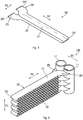
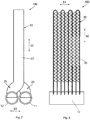
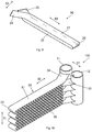
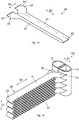
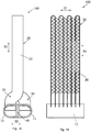
- Figs. 1 , 5 , 9 and 13 show heat exchange tubes according to embodiments of the present invention
- figs. 2 to 4 , 6 to 8 , 10 to 12 and 14 to 16 show heat exchangers according to embodiments of the present invention, wherein an end cap for an end of a manifold of the heat exchanger has been omitted, hence that end of the heat exchange tube which is inserted into the manifold can be seen.
- a heat exchanger 100 such as a micro-channel heat exchanger according to an embodiment of the present invention comprises: a first manifold 11 and a second manifold 12 disposed on the same side of the heat exchanger 100 (e.g.
- a first manifold 11 and a second manifold 12 disposed substantially in parallel, at an angle or side by side, or a first manifold 11 and a second manifold 12 formed from one tube by means of a longitudinal partition plate); and a plurality of heat exchange tubes 20 such as flat tubes, each heat exchange tube 20 having: a first heat exchange part 21 and a second heat exchange part 22 which are substantially parallel; and a first end 24 and a second end 25 connected to the first heat exchange part 21 and the second heat exchange part 22 respectively, with the first end 24 deviating from a center line (i.e.
- each heat exchange tube 20 also has a connecting part 23 connecting the first heat exchange part 21 and the second heat exchange part 22.
- At least one heat exchange tube 20 is an integral whole, and the connecting part 23 of the at least one heat exchange tube 20 may be formed by bending.
- each heat exchange tube 20 also has a connecting part 23 connecting the first heat exchange part 21 and the second heat exchange part 22, with at least one of the connecting parts 23 being a U-shaped tube, e.g. a single U-shaped tube is connected to the first heat exchange part 21 and the second heat exchange part 22 by welding.
- each of the heat exchange tubes 21 is an integral whole.
- a refrigerant can flow into the heat exchanger through the first manifold 11 and flow out of the heat exchanger through the second manifold 12.
- the first end 24 and the second end 25 are opposite the connecting part 23.
- the heat exchanger 100 also comprises: fins 30, disposed between the first heat exchange part 21 and the second heat exchange part 22.
- the first end 24 deviates from the center line of the first heat exchange part 21 by bending twice, and each heat exchange tube 20 comprises two heat exchange parts.
- each heat exchange tube 20 also has a plurality of third heat exchange parts disposed between the first heat exchange part 21 and the second heat exchange part 22, and the first heat exchange part 21, the second heat exchange part 22 and the third heat exchange parts are substantially parallel.
- Each heat exchange tube 20 also has a plurality of connecting parts 23 connecting adjacent heat exchange parts amongst the first heat exchange part 21, the third heat exchange parts and the second heat exchange part 22, with at least one of the connecting parts 23 being formed by bending, or being a U-shaped tube.
- the heat exchanger 100 also comprises: fins 30, disposed between adjacent heat exchange parts amongst the first heat exchange part 21, the third heat exchange parts and the second heat exchange part 22.
- the first heat exchange part 21 and the second heat exchange part 22 are arranged in a first direction D1, and extend in a second direction D2 which is substantially perpendicular to the first direction D1, and said same side of the heat exchanger 100 is the same side in the second direction D2, in a plane defined by the first direction D1 and the second direction D2.
- the second end 25 deviates from a center line (i.e. an axis, axial center line or longitudinal center line of a tube section forming the heat exchange part) of the second heat exchange part 22 by curving, and the first end 24 and the second end 25 deviate in opposite directions.
- a center line i.e. an axis, axial center line or longitudinal center line of a tube section forming the heat exchange part
- each heat exchange tube 20 comprises two heat exchange parts; by forming a plurality of connecting parts 23, each heat exchange tube 20 may comprise four or more heat exchange parts.
- the first heat exchange part 21 and the second heat exchange part 22 are arranged in the first direction D1 (i.e. an axial direction of the first manifold 11 and the second manifold 12), and extend in the second direction D2 which is substantially perpendicular to the first direction D1; and the first end 24 deviates from the center line of the first heat exchange part 21 in a third direction D3 which is substantially perpendicular to the first direction D1 and the second direction D2.
- the first manifold 11 and the second manifold 12 are disposed in the third direction D3.
- the first end 24 deviates from the center line of the first heat exchange part 21 by curving substantially in a plane defined by the second direction D2 and the third direction D3.
- the first end 24 and the first heat exchange part 21 of each heat exchange tube 20 may lie substantially in the plane defined by the second direction D2 and the third direction D3.
- the first heat exchange part 21 and the second heat exchange part 22 are arranged in the first direction D1 (i.e. the axial direction of the first manifold 11 and the second manifold 12), and extend in the second direction D2 which is substantially perpendicular to the first direction D1; the first end 24 deviates from the center line of the first heat exchange part 21 in the third direction D3 which is substantially perpendicular to the first direction D1 and the second direction D2, and the second end 25 deviates from the center line of the second heat exchange part 22 in the third direction D3 which is substantially perpendicular to the first direction D1 and the second direction D2.
- the first end 24 deviates from the center line of the first heat exchange part 21 by curving substantially in the plane defined by the second direction D2 and the third direction D3, and the second end 25 deviates from the center line of the second heat exchange part 22 by curving substantially in the plane defined by the second direction D2 and the third direction D3.
- the first end 24 and the first heat exchange part 21 of each heat exchange tube 20 lie substantially in the plane defined by the second direction D2 and the third direction D3
- the second end 25 and the second heat exchange part 22 of each heat exchange tube 20 lie substantially in the plane defined by the second direction D2 and the third direction D3.
- a direction of extension of a part 241, connected to the first manifold 11, of the first end 24 of each heat exchange tube 20 is substantially the same as the direction of extension of the first heat exchange part 21.
- the part 241, connected to the first manifold 11, of the first end 24 of each heat exchange tube 20 extends substantially in the second direction D2.
- the direction of extension of the part 241, connected to the first manifold 11, of the first end 24 of each heat exchange tube 20 is substantially the same as the direction of extension of the first heat exchange part 21, and a direction of extension of a part 251, connected to the second manifold 12, of the second end 25 of each heat exchange tube 20 is substantially the same as the direction of extension of the second heat exchange part 22.
- the part 241, connected to the first manifold 11, of the first end 24 of each heat exchange tube 20 extends substantially in the second direction D2
- the part 251, connected to the second manifold 12, of the second end 25 of each heat exchange tube 20 extends substantially in the second direction D2.
- the first end 24 (e.g. a center line of the first end 24 (i.e. an axis, axial center line or longitudinal center line of a tube section forming the end)) of each heat exchange tube 20 is inclined relative to the first heat exchange part 21 (e.g. the center line of the first heat exchange part 21 (i.e. the axis, axial center line or longitudinal center line of the tube section forming the first heat exchange part 21)).
- the first heat exchange part 21 e.g. the center line of the first heat exchange part 21 (i.e. the axis, axial center line or longitudinal center line of the tube section forming the first heat exchange part 21)).
- each heat exchange tube 20 comprises two heat exchange parts; by forming a plurality of connecting parts 23, each heat exchange tube 20 may comprise four or more heat exchange parts.
- each heat exchange tube 20 is inclined relative to the first heat exchange part 21, and the second end 25 (e.g. a center line of the second end 25 (i.e. an axis, axial center line or longitudinal center line of a tube section forming the end)) of each heat exchange tube 20 is inclined relative to the second heat exchange part 22 (e.g. the center line of the second heat exchange part 22 (i.e. the axis, axial center line or longitudinal center line of the tube section forming the second heat exchange part 22)).
- the second heat exchange part 22 e.g. the center line of the second heat exchange part 22 (i.e. the axis, axial center line or longitudinal center line of the tube section forming the second heat exchange part 22)
- a heat insulating space 40 or heat insulating element may be disposed between the first manifold 11 and the second manifold 12, and may prevent heat exchange between the two manifolds and the formation of a heat bridge, which would affect the heat exchange effect of the heat exchanger.
- the first manifold 11 and the second manifold 12 may be two separate manifolds, but could also be a first manifold 11 and a second manifold 12 formed from one tube by means of a longitudinal partition plate.
- the longitudinal partition plate may be two partition plates; the two partition plates may be integral with pipe walls of the pipes, but could also be separate.
- the first manifold 11 and the second manifold 12 are manifolds with D-shaped cross sections, and substantially flat surfaces of the two manifolds with the D-shaped cross sections face each other.
- a gap is provided between the first manifold 11 and the second manifold 12.
- the heat insulating element may be disposed in the gap.
- the heat exchanger according to an embodiment of the present invention may be used in the fields of heating, ventilating and air conditioning, motor vehicles, refrigeration and transport, and may be a micro-channel heat exchanger or a parallel-flow heat exchanger, etc.
- the heat exchanger according to an embodiment of the present invention can reduce costs, increase the wind field uniformity and output wind temperature uniformity of a micro-channel heat pump evaporator, and increase the utilization rate of the heat exchange area.
- a partition plate may be disposed in the manifold, so as to form different circuits.
- the circuit length may be adjusted as required (with the heat exchange tube being bent a number of times).
- the manifolds are arranged at a single side, so connecting pipelines and manifolds are saved, and costs are lower.
- a single row of flat tubes may be employed, so that wind resistance is low.
Claims (17)
- Échangeur de chaleur (100), comprenant :un premier collecteur (11) et un second collecteur (12) disposée sur la même face de l'échangeur de chaleur (100) ; etune pluralité de tubes d'échange de chaleur plats (20), chaque tube d'échange de chaleur (20) comportant :une première pièce d'échange de chaleur (21) et une deuxième pièce d'échange de chaleur (22) qui sont substantiellement parallèles ; etune première extrémité (24) et une seconde extrémité (25) connectées à la première pièce d'échange de chaleur (21) et à la deuxième pièce d'échange de chaleur (22) respectivement, la première extrémité (24) déviant d'une ligne centrale de la première pièce d'échange de chaleur (21) par cintrage, de sorte que la première extrémité (24) et la seconde extrémité (25) sont connectées à, et en communication fluidique avec, le premier collecteur (11) et le second collecteur (12) respectivement,la première pièce d'échange de chaleur (21) et la deuxième pièce d'échange de chaleur (22) étant disposées dans un premier sens (D1), et s'étendant dans un deuxième sens (D2) qui est substantiellement perpendiculaire au premier sens (D1), etladite même face de l'échangeur de chaleur (100) étant la même face dans le deuxième sens (D2), dans un plan défini par le premier sens (D1) et le deuxième sens (D2), caractérisé en ce quechaque tube d'échange de chaleur (20) comporte en outre une pièce de connexion (23) connectant la première pièce d'échange de chaleur (21) et la deuxième pièce d'échange de chaleur (22) ; qu'au moins une des pièces de connexion (23) est un tube en forme de U, ou qu'au moins un tube d'échange de chaleur (20) est un ensemble intégral et que la pièce de connexion (23) de l'au moins un tube d'échange de chaleur (20) est formée par cintrage, des ailettes (30) étant disposées entre la première pièce d'échange de chaleur (21) et la deuxième pièce d'échange de chaleur (22).
- Échangeur de chaleur selon la revendication 1, caractérisé en ce que :
la seconde extrémité (25) dévie d'une ligne centrale de la deuxième pièce d'échange de chaleur (22) par cintrage, et que la première extrémité (24) et la seconde extrémité (25) dévient dans des sens opposés. - Échangeur de chaleur selon la revendication 1, caractérisé en ce que :la première pièce d'échange de chaleur (21) et la deuxième pièce d'échange de chaleur (22) sont disposées dans un premier sens (D1), et s'étendent dans un deuxième sens (D2) qui est substantiellement perpendiculaire au premier sens (D1), etque la première extrémité (24) dévie de la ligne centrale de la première pièce d'échange de chaleur (21) dans un troisième sens (D3) qui est substantiellement perpendiculaire au premier sens (D1) et au deuxième sens (D2).
- Échangeur de chaleur selon la revendication 2, caractérisé en ce que :la première pièce d'échange de chaleur (21) et la deuxième pièce d'échange de chaleur (22) sont disposées dans un premier sens (D1), et s'étendent dans un deuxième sens (D2) qui est substantiellement perpendiculaire au premier sens (D1), etla première extrémité dévie (24) de la ligne centrale de la première pièce d'échange de chaleur (21) dans un troisième sens (D3) qui est substantiellement perpendiculaire au premier sens (D1) et au deuxième sens (D2), etla seconde extrémité (25) dévie de la ligne centrale de la deuxième pièce d'échange de chaleur (22) dans un troisième sens (D3) qui est substantiellement perpendiculaire au premier sens (D1) et au deuxième sens (D2).
- Échangeur de chaleur selon la revendication 1, caractérisé en ce que :
chaque tube d'échange de chaleur (20) comporte en outre une pluralité de troisièmes pièces d'échange de chaleur disposées entre la première pièce d'échange de chaleur (21) et la deuxième pièce d'échange de chaleur (22), et que la première pièce d'échange de chaleur (21), la deuxième pièce d'échange de chaleur (22) et les troisièmes pièces d'échange de chaleur sont substantiellement parallèles. - Échangeur de chaleur selon la revendication 5, caractérisé en ce que :
chaque tube d'échange de chaleur (20) comporte en outre une pluralité de pièces de connexion (23) connectant les pièces d'échange de chaleur adjacentes parmi la première pièce d'échange de chaleur (21), les troisièmes pièces d'échange de chaleur et la deuxième pièce d'échange de chaleur (22), au moins une des pièces de connexion (23) étant formée par cintrage, ou étant un tube en forme de U. - Échangeur de chaleur selon la revendication 1, caractérisé en outre par :
une ailette (30) disposée entre la première pièce d'échange de chaleur (21) et la deuxième pièce d'échange de chaleur (22). - Échangeur de chaleur selon la revendication 5, caractérisé en ce que :
une ailette (30) disposée entre des pièces d'échange de chaleur adjacentes parmi la première pièce d'échange de chaleur (21), les troisièmes pièces d'échange de chaleur et la deuxième pièce d'échange de chaleur (22). - Échangeur de chaleur selon la revendication 1, caractérisé en ce que :
la première extrémité (24) de chaque tube d'échange de chaleur (20) est inclinée par rapport à la première pièce d'échange de chaleur (21). - Échangeur de chaleur selon la revendication 2, caractérisé en ce que :la première extrémité (24) de chaque tube d'échange de chaleur est inclinée par rapport à la première pièce d'échange de chaleur (21), etla seconde extrémité (25) de chaque tube d'échange de chaleur (20) est inclinée par rapport à la deuxième pièce d'échange de chaleur (22).
- Échangeur de chaleur selon la revendication 3, caractérisé en ce que :
la première extrémité (24) dévie de la ligne centrale de la première pièce d'échange de chaleur (21) par cintrage substantiellement dans un plan défini par le deuxième sens (D2) et le troisième sens (D3). - Échangeur de chaleur selon la revendication 4, caractérisé en ce que :la première extrémité (24) dévie de la ligne centrale de la première pièce d'échange de chaleur (21) par cintrage substantiellement dans un plan défini par le deuxième sens (D2) et le troisième sens (D3), etla seconde extrémité (25) dévie de la ligne centrale de la deuxième pièce d'échange de chaleur (22) par cintrage substantiellement dans le plan défini par le deuxième sens (D2) et le troisième sens (D3).
- Échangeur de chaleur selon la revendication 3, caractérisé en ce que :
la première extrémité (24) et la première pièce d'échange de chaleur (21) de chaque tube d'échange de chaleur (20) se situent substantiellement dans un plan défini par le deuxième sens (D2) et le troisième sens (D3) . - Échangeur de chaleur selon la revendication 4, caractérisé en ce que :la première extrémité (24) et la première pièce d'échange de chaleur (21) de chaque tube d'échange de chaleur (20) se situent substantiellement dans un plan défini par le deuxième sens (D2) et le troisième sens (D3), etla seconde extrémité (25) et la deuxième pièce d'échange de chaleur (22) de chaque tube d'échange de chaleur (20) se situent substantiellement dans un plan défini par le deuxième sens (D2) et le troisième sens (D3).
- Échangeur de chaleur selon la revendication 1, caractérisé en ce que :
le premier collecteur (11) et le second collecteur (12) sont des collecteurs (11,12) ayant des sections transversales en forme de D, et que les surfaces substantiellement plates des collecteurs (11,12) ayant les sections transversales en forme de D sont face à face. - Échangeur de chaleur selon la revendication 1 ou 15, caractérisé en outre par :
un élément isolant thermique (40) disposé entre le premier collecteur (11) et le second collecteur (12). - Échangeur de chaleur selon la revendication 1, caractérisé en ce que :
chacun des tubes d'échange de chaleur (20) est un ensemble intégral.
Applications Claiming Priority (2)
| Application Number | Priority Date | Filing Date | Title |
|---|---|---|---|
| CN201510711462.9A CN106642826B (zh) | 2015-10-28 | 2015-10-28 | 换热器 |
| PCT/CN2016/093023 WO2017071355A1 (fr) | 2015-10-28 | 2016-08-03 | Échangeur de chaleur |
Publications (3)
| Publication Number | Publication Date |
|---|---|
| EP3370019A1 EP3370019A1 (fr) | 2018-09-05 |
| EP3370019A4 EP3370019A4 (fr) | 2019-06-26 |
| EP3370019B1 true EP3370019B1 (fr) | 2020-06-17 |
Family
ID=58631279
Family Applications (1)
| Application Number | Title | Priority Date | Filing Date |
|---|---|---|---|
| EP16858794.7A Active EP3370019B1 (fr) | 2015-10-28 | 2016-08-03 | Échangeur de chaleur |
Country Status (6)
| Country | Link |
|---|---|
| US (1) | US20180340746A1 (fr) |
| EP (1) | EP3370019B1 (fr) |
| JP (1) | JP7125344B2 (fr) |
| KR (1) | KR102520736B1 (fr) |
| CN (1) | CN106642826B (fr) |
| WO (1) | WO2017071355A1 (fr) |
Families Citing this family (6)
| Publication number | Priority date | Publication date | Assignee | Title |
|---|---|---|---|---|
| CN109900144B (zh) * | 2017-12-08 | 2021-03-16 | 丹佛斯微通道换热器(嘉兴)有限公司 | 换热器和具有该换热器的换热装置 |
| US20190368819A1 (en) * | 2018-05-30 | 2019-12-05 | Johnson Controls Technology Company | Heat exchanger for hvac unit |
| CN111322795A (zh) | 2018-12-14 | 2020-06-23 | 丹佛斯有限公司 | 换热器和空调系统 |
| EP4242556A1 (fr) * | 2020-11-03 | 2023-09-13 | Danfoss A/S | Échangeur de chaleur et système de climatisation doté de celui-ci |
| US20220221226A1 (en) * | 2021-01-13 | 2022-07-14 | Mahle International Gmbh | Flat tube and heat exchanger |
| US20220252349A1 (en) | 2021-02-11 | 2022-08-11 | Mahle International Gmbh | Heat exchanger |
Family Cites Families (23)
| Publication number | Priority date | Publication date | Assignee | Title |
|---|---|---|---|---|
| JP3305460B2 (ja) * | 1993-11-24 | 2002-07-22 | 昭和電工株式会社 | 熱交換器 |
| DE19830863A1 (de) * | 1998-07-10 | 2000-01-13 | Behr Gmbh & Co | Flachrohr mit Querversatz-Umkehrbogenabschnitt und damit aufgebauter Wärmeübertrager |
| ATE193371T1 (de) * | 1998-09-03 | 2000-06-15 | Genebrev Sa | Radiator für heizungsanlage mit flüssigkeitsumlauf |
| KR20040105439A (ko) * | 2003-06-09 | 2004-12-16 | 한라공조주식회사 | 이산화탄소용 열교환기 |
| EP1844285A4 (fr) * | 2005-02-02 | 2011-12-21 | Carrier Corp | Echangeur thermique a tubes plats multicanaux |
| FR2890730B1 (fr) | 2005-09-13 | 2007-10-19 | Valeo Systemes Thermiques | Element de circuit a tubes plats, et echangeur de chaleur muni de tels elements |
| CN101432590B (zh) * | 2006-04-14 | 2012-01-25 | 三菱电机株式会社 | 热交换器及制冷空调装置 |
| FR2899959B1 (fr) * | 2006-04-14 | 2008-08-08 | Valeo Systemes Thermiques | Echangeur de chaleur ameliore et module d'echange de chaleur comportant un tel echangeur |
| DE102006033771A1 (de) * | 2006-07-21 | 2008-01-24 | Modine Manufacturing Co., Racine | Wärmetauscher |
| TWI361880B (en) * | 2008-11-17 | 2012-04-11 | Heat exchanging module and working fluid distributor thereof and method for manufacturing heat exchange module | |
| JP2010169289A (ja) * | 2009-01-21 | 2010-08-05 | Nikkei Nekko Kk | 屈曲状熱交換器及びその製造方法 |
| CN101846465B (zh) * | 2010-04-13 | 2011-11-09 | 三花丹佛斯(杭州)微通道换热器有限公司 | 换热器 |
| JP5796564B2 (ja) * | 2011-11-30 | 2015-10-21 | 株式会社デンソー | 熱交換器 |
| JP5884530B2 (ja) * | 2012-02-03 | 2016-03-15 | 富士通株式会社 | ラジエータ及びそれを備えた電子機器 |
| EP2948724B1 (fr) * | 2013-01-28 | 2019-05-29 | Carrier Corporation | Unité d'échange thermique à plusieurs faisceaux de tubes dotée d'un ensemble de collecteur |
| WO2014146505A1 (fr) * | 2013-03-21 | 2014-09-25 | 杭州三花微通道换热器有限公司 | Échangeur de chaleur de type à courbure et méthode de fabrication de celui-ci |
| CN203310165U (zh) * | 2013-05-14 | 2013-11-27 | 广东美的制冷设备有限公司 | 平行流换热器及空调器 |
| CN103277942B (zh) * | 2013-05-14 | 2015-06-03 | 广东美的制冷设备有限公司 | 平行流换热器及空调器 |
| CN103245132B (zh) * | 2013-05-29 | 2015-09-23 | 上海交通大学 | 有利于减少制冷剂充注量的微通道换热器 |
| CN104596153B (zh) * | 2013-10-31 | 2018-09-28 | 杭州三花微通道换热器有限公司 | 微通道换热器 |
| CN103697745A (zh) * | 2014-01-20 | 2014-04-02 | 丹佛斯微通道换热器(嘉兴)有限公司 | 集流管组件以及具有该集流管组件的换热器 |
| DE102014206612A1 (de) * | 2014-04-04 | 2015-10-29 | Mahle International Gmbh | Wärmetauscher |
| CN204188033U (zh) * | 2014-09-29 | 2015-03-04 | 杭州三花微通道换热器有限公司 | 一种换热器 |
-
2015
- 2015-10-28 CN CN201510711462.9A patent/CN106642826B/zh active Active
-
2016
- 2016-08-03 EP EP16858794.7A patent/EP3370019B1/fr active Active
- 2016-08-03 WO PCT/CN2016/093023 patent/WO2017071355A1/fr active Application Filing
- 2016-08-03 US US15/771,539 patent/US20180340746A1/en not_active Abandoned
- 2016-08-03 JP JP2018521359A patent/JP7125344B2/ja active Active
- 2016-08-03 KR KR1020187013851A patent/KR102520736B1/ko active IP Right Grant
Non-Patent Citations (1)
| Title |
|---|
| None * |
Also Published As
| Publication number | Publication date |
|---|---|
| US20180340746A1 (en) | 2018-11-29 |
| CN106642826A (zh) | 2017-05-10 |
| WO2017071355A1 (fr) | 2017-05-04 |
| CN106642826B (zh) | 2019-04-19 |
| KR20180077188A (ko) | 2018-07-06 |
| EP3370019A1 (fr) | 2018-09-05 |
| JP7125344B2 (ja) | 2022-08-24 |
| KR102520736B1 (ko) | 2023-04-11 |
| EP3370019A4 (fr) | 2019-06-26 |
| JP2018532093A (ja) | 2018-11-01 |
Similar Documents
| Publication | Publication Date | Title |
|---|---|---|
| EP3370019B1 (fr) | Échangeur de chaleur | |
| EP2930456B1 (fr) | Appareil d'échange thermique à tubes plats, et unité extérieure pour climatiseur le comportant | |
| CN103925826A (zh) | 热交换器用管 | |
| US20140131022A1 (en) | Heat exchanger utilizing tubular structures having internal flow altering members and external chamber assemblies | |
| CN105452796A (zh) | 换热器用散热片 | |
| JP2015017776A5 (fr) | ||
| WO2015106726A1 (fr) | Ensemble de conduites collectrices et echangeur thermique equipe d'un ensemble de conduites collectrices | |
| US20130240177A1 (en) | Nested heat exchanger | |
| US20190195572A1 (en) | Heat exchanger | |
| EP2962055B1 (fr) | Solution d'ailette associée à un échangeur de chaleur à base de microcanaux | |
| CN104089517A (zh) | 用于换热器的翅片和具有该翅片的换热器 | |
| CN105737453B (zh) | 冷却装置及其使用方法 | |
| CN211855020U (zh) | 换热管和具有其的换热器 | |
| JP2016148480A (ja) | 熱交換器 | |
| EP3224565B1 (fr) | Échangeur de chaleur à microcanaux tolérant au gel | |
| JP7044969B2 (ja) | 熱交換器 | |
| US20170321969A1 (en) | Fin for a finned pack for heat exchangers, as well as heat exchanger | |
| US10830542B2 (en) | Method for manufacturing a multiple manifold assembly having internal communication ports | |
| JP5591285B2 (ja) | 熱交換器および空気調和機 | |
| EP3141862B1 (fr) | Dispositif d'étanchéité intégré et échangeur thermique l'utilisant | |
| JP2015535591A (ja) | 熱交換手段のチューブ要素 | |
| US9453599B2 (en) | Bi-channel coolant tube having crossover channels to allow coolant interaction | |
| EP3572743B1 (fr) | Ensemble échangeur de chaleur | |
| WO2013105490A1 (fr) | Échangeur thermique | |
| JP6583729B2 (ja) | 熱交換器 |
Legal Events
| Date | Code | Title | Description |
|---|---|---|---|
| STAA | Information on the status of an ep patent application or granted ep patent |
Free format text: STATUS: THE INTERNATIONAL PUBLICATION HAS BEEN MADE |
|
| PUAI | Public reference made under article 153(3) epc to a published international application that has entered the european phase |
Free format text: ORIGINAL CODE: 0009012 |
|
| STAA | Information on the status of an ep patent application or granted ep patent |
Free format text: STATUS: REQUEST FOR EXAMINATION WAS MADE |
|
| 17P | Request for examination filed |
Effective date: 20180426 |
|
| AK | Designated contracting states |
Kind code of ref document: A1 Designated state(s): AL AT BE BG CH CY CZ DE DK EE ES FI FR GB GR HR HU IE IS IT LI LT LU LV MC MK MT NL NO PL PT RO RS SE SI SK SM TR |
|
| AX | Request for extension of the european patent |
Extension state: BA ME |
|
| DAV | Request for validation of the european patent (deleted) | ||
| DAX | Request for extension of the european patent (deleted) | ||
| A4 | Supplementary search report drawn up and despatched |
Effective date: 20190527 |
|
| RIC1 | Information provided on ipc code assigned before grant |
Ipc: F28F 9/02 20060101ALI20190521BHEP Ipc: F28D 1/047 20060101ALI20190521BHEP Ipc: F28D 21/00 20060101ALI20190521BHEP Ipc: F28F 1/02 20060101ALI20190521BHEP Ipc: F25B 39/00 20060101AFI20190521BHEP |
|
| GRAP | Despatch of communication of intention to grant a patent |
Free format text: ORIGINAL CODE: EPIDOSNIGR1 |
|
| STAA | Information on the status of an ep patent application or granted ep patent |
Free format text: STATUS: GRANT OF PATENT IS INTENDED |
|
| INTG | Intention to grant announced |
Effective date: 20200131 |
|
| GRAS | Grant fee paid |
Free format text: ORIGINAL CODE: EPIDOSNIGR3 |
|
| GRAA | (expected) grant |
Free format text: ORIGINAL CODE: 0009210 |
|
| STAA | Information on the status of an ep patent application or granted ep patent |
Free format text: STATUS: THE PATENT HAS BEEN GRANTED |
|
| AK | Designated contracting states |
Kind code of ref document: B1 Designated state(s): AL AT BE BG CH CY CZ DE DK EE ES FI FR GB GR HR HU IE IS IT LI LT LU LV MC MK MT NL NO PL PT RO RS SE SI SK SM TR |
|
| REG | Reference to a national code |
Ref country code: GB Ref legal event code: FG4D |
|
| REG | Reference to a national code |
Ref country code: CH Ref legal event code: EP |
|
| REG | Reference to a national code |
Ref country code: IE Ref legal event code: FG4D |
|
| REG | Reference to a national code |
Ref country code: DE Ref legal event code: R096 Ref document number: 602016038480 Country of ref document: DE |
|
| REG | Reference to a national code |
Ref country code: AT Ref legal event code: REF Ref document number: 1281789 Country of ref document: AT Kind code of ref document: T Effective date: 20200715 |
|
| PG25 | Lapsed in a contracting state [announced via postgrant information from national office to epo] |
Ref country code: FI Free format text: LAPSE BECAUSE OF FAILURE TO SUBMIT A TRANSLATION OF THE DESCRIPTION OR TO PAY THE FEE WITHIN THE PRESCRIBED TIME-LIMIT Effective date: 20200617 Ref country code: GR Free format text: LAPSE BECAUSE OF FAILURE TO SUBMIT A TRANSLATION OF THE DESCRIPTION OR TO PAY THE FEE WITHIN THE PRESCRIBED TIME-LIMIT Effective date: 20200918 Ref country code: NO Free format text: LAPSE BECAUSE OF FAILURE TO SUBMIT A TRANSLATION OF THE DESCRIPTION OR TO PAY THE FEE WITHIN THE PRESCRIBED TIME-LIMIT Effective date: 20200917 Ref country code: SE Free format text: LAPSE BECAUSE OF FAILURE TO SUBMIT A TRANSLATION OF THE DESCRIPTION OR TO PAY THE FEE WITHIN THE PRESCRIBED TIME-LIMIT Effective date: 20200617 Ref country code: LT Free format text: LAPSE BECAUSE OF FAILURE TO SUBMIT A TRANSLATION OF THE DESCRIPTION OR TO PAY THE FEE WITHIN THE PRESCRIBED TIME-LIMIT Effective date: 20200617 |
|
| REG | Reference to a national code |
Ref country code: LT Ref legal event code: MG4D |
|
| REG | Reference to a national code |
Ref country code: NL Ref legal event code: MP Effective date: 20200617 |
|
| PG25 | Lapsed in a contracting state [announced via postgrant information from national office to epo] |
Ref country code: RS Free format text: LAPSE BECAUSE OF FAILURE TO SUBMIT A TRANSLATION OF THE DESCRIPTION OR TO PAY THE FEE WITHIN THE PRESCRIBED TIME-LIMIT Effective date: 20200617 Ref country code: BG Free format text: LAPSE BECAUSE OF FAILURE TO SUBMIT A TRANSLATION OF THE DESCRIPTION OR TO PAY THE FEE WITHIN THE PRESCRIBED TIME-LIMIT Effective date: 20200917 Ref country code: LV Free format text: LAPSE BECAUSE OF FAILURE TO SUBMIT A TRANSLATION OF THE DESCRIPTION OR TO PAY THE FEE WITHIN THE PRESCRIBED TIME-LIMIT Effective date: 20200617 Ref country code: HR Free format text: LAPSE BECAUSE OF FAILURE TO SUBMIT A TRANSLATION OF THE DESCRIPTION OR TO PAY THE FEE WITHIN THE PRESCRIBED TIME-LIMIT Effective date: 20200617 |
|
| REG | Reference to a national code |
Ref country code: AT Ref legal event code: MK05 Ref document number: 1281789 Country of ref document: AT Kind code of ref document: T Effective date: 20200617 |
|
| PG25 | Lapsed in a contracting state [announced via postgrant information from national office to epo] |
Ref country code: AL Free format text: LAPSE BECAUSE OF FAILURE TO SUBMIT A TRANSLATION OF THE DESCRIPTION OR TO PAY THE FEE WITHIN THE PRESCRIBED TIME-LIMIT Effective date: 20200617 Ref country code: NL Free format text: LAPSE BECAUSE OF FAILURE TO SUBMIT A TRANSLATION OF THE DESCRIPTION OR TO PAY THE FEE WITHIN THE PRESCRIBED TIME-LIMIT Effective date: 20200617 |
|
| PG25 | Lapsed in a contracting state [announced via postgrant information from national office to epo] |
Ref country code: ES Free format text: LAPSE BECAUSE OF FAILURE TO SUBMIT A TRANSLATION OF THE DESCRIPTION OR TO PAY THE FEE WITHIN THE PRESCRIBED TIME-LIMIT Effective date: 20200617 Ref country code: IT Free format text: LAPSE BECAUSE OF FAILURE TO SUBMIT A TRANSLATION OF THE DESCRIPTION OR TO PAY THE FEE WITHIN THE PRESCRIBED TIME-LIMIT Effective date: 20200617 Ref country code: SM Free format text: LAPSE BECAUSE OF FAILURE TO SUBMIT A TRANSLATION OF THE DESCRIPTION OR TO PAY THE FEE WITHIN THE PRESCRIBED TIME-LIMIT Effective date: 20200617 Ref country code: AT Free format text: LAPSE BECAUSE OF FAILURE TO SUBMIT A TRANSLATION OF THE DESCRIPTION OR TO PAY THE FEE WITHIN THE PRESCRIBED TIME-LIMIT Effective date: 20200617 Ref country code: EE Free format text: LAPSE BECAUSE OF FAILURE TO SUBMIT A TRANSLATION OF THE DESCRIPTION OR TO PAY THE FEE WITHIN THE PRESCRIBED TIME-LIMIT Effective date: 20200617 Ref country code: RO Free format text: LAPSE BECAUSE OF FAILURE TO SUBMIT A TRANSLATION OF THE DESCRIPTION OR TO PAY THE FEE WITHIN THE PRESCRIBED TIME-LIMIT Effective date: 20200617 Ref country code: CZ Free format text: LAPSE BECAUSE OF FAILURE TO SUBMIT A TRANSLATION OF THE DESCRIPTION OR TO PAY THE FEE WITHIN THE PRESCRIBED TIME-LIMIT Effective date: 20200617 Ref country code: PT Free format text: LAPSE BECAUSE OF FAILURE TO SUBMIT A TRANSLATION OF THE DESCRIPTION OR TO PAY THE FEE WITHIN THE PRESCRIBED TIME-LIMIT Effective date: 20201019 |
|
| PG25 | Lapsed in a contracting state [announced via postgrant information from national office to epo] |
Ref country code: PL Free format text: LAPSE BECAUSE OF FAILURE TO SUBMIT A TRANSLATION OF THE DESCRIPTION OR TO PAY THE FEE WITHIN THE PRESCRIBED TIME-LIMIT Effective date: 20200617 Ref country code: SK Free format text: LAPSE BECAUSE OF FAILURE TO SUBMIT A TRANSLATION OF THE DESCRIPTION OR TO PAY THE FEE WITHIN THE PRESCRIBED TIME-LIMIT Effective date: 20200617 Ref country code: IS Free format text: LAPSE BECAUSE OF FAILURE TO SUBMIT A TRANSLATION OF THE DESCRIPTION OR TO PAY THE FEE WITHIN THE PRESCRIBED TIME-LIMIT Effective date: 20201017 |
|
| REG | Reference to a national code |
Ref country code: DE Ref legal event code: R097 Ref document number: 602016038480 Country of ref document: DE |
|
| PG25 | Lapsed in a contracting state [announced via postgrant information from national office to epo] |
Ref country code: MC Free format text: LAPSE BECAUSE OF FAILURE TO SUBMIT A TRANSLATION OF THE DESCRIPTION OR TO PAY THE FEE WITHIN THE PRESCRIBED TIME-LIMIT Effective date: 20200617 |
|
| REG | Reference to a national code |
Ref country code: CH Ref legal event code: PL |
|
| PLBE | No opposition filed within time limit |
Free format text: ORIGINAL CODE: 0009261 |
|
| STAA | Information on the status of an ep patent application or granted ep patent |
Free format text: STATUS: NO OPPOSITION FILED WITHIN TIME LIMIT |
|
| PG25 | Lapsed in a contracting state [announced via postgrant information from national office to epo] |
Ref country code: CH Free format text: LAPSE BECAUSE OF NON-PAYMENT OF DUE FEES Effective date: 20200831 Ref country code: DK Free format text: LAPSE BECAUSE OF FAILURE TO SUBMIT A TRANSLATION OF THE DESCRIPTION OR TO PAY THE FEE WITHIN THE PRESCRIBED TIME-LIMIT Effective date: 20200617 Ref country code: LU Free format text: LAPSE BECAUSE OF NON-PAYMENT OF DUE FEES Effective date: 20200803 Ref country code: LI Free format text: LAPSE BECAUSE OF NON-PAYMENT OF DUE FEES Effective date: 20200831 |
|
| 26N | No opposition filed |
Effective date: 20210318 |
|
| GBPC | Gb: european patent ceased through non-payment of renewal fee |
Effective date: 20200917 |
|
| REG | Reference to a national code |
Ref country code: BE Ref legal event code: MM Effective date: 20200831 |
|
| PG25 | Lapsed in a contracting state [announced via postgrant information from national office to epo] |
Ref country code: SI Free format text: LAPSE BECAUSE OF FAILURE TO SUBMIT A TRANSLATION OF THE DESCRIPTION OR TO PAY THE FEE WITHIN THE PRESCRIBED TIME-LIMIT Effective date: 20200617 |
|
| PG25 | Lapsed in a contracting state [announced via postgrant information from national office to epo] |
Ref country code: FR Free format text: LAPSE BECAUSE OF NON-PAYMENT OF DUE FEES Effective date: 20200817 |
|
| PG25 | Lapsed in a contracting state [announced via postgrant information from national office to epo] |
Ref country code: GB Free format text: LAPSE BECAUSE OF NON-PAYMENT OF DUE FEES Effective date: 20200917 Ref country code: IE Free format text: LAPSE BECAUSE OF NON-PAYMENT OF DUE FEES Effective date: 20200803 Ref country code: BE Free format text: LAPSE BECAUSE OF NON-PAYMENT OF DUE FEES Effective date: 20200831 |
|
| PG25 | Lapsed in a contracting state [announced via postgrant information from national office to epo] |
Ref country code: TR Free format text: LAPSE BECAUSE OF FAILURE TO SUBMIT A TRANSLATION OF THE DESCRIPTION OR TO PAY THE FEE WITHIN THE PRESCRIBED TIME-LIMIT Effective date: 20200617 Ref country code: MT Free format text: LAPSE BECAUSE OF FAILURE TO SUBMIT A TRANSLATION OF THE DESCRIPTION OR TO PAY THE FEE WITHIN THE PRESCRIBED TIME-LIMIT Effective date: 20200617 Ref country code: CY Free format text: LAPSE BECAUSE OF FAILURE TO SUBMIT A TRANSLATION OF THE DESCRIPTION OR TO PAY THE FEE WITHIN THE PRESCRIBED TIME-LIMIT Effective date: 20200617 |
|
| PG25 | Lapsed in a contracting state [announced via postgrant information from national office to epo] |
Ref country code: MK Free format text: LAPSE BECAUSE OF FAILURE TO SUBMIT A TRANSLATION OF THE DESCRIPTION OR TO PAY THE FEE WITHIN THE PRESCRIBED TIME-LIMIT Effective date: 20200617 |
|
| P01 | Opt-out of the competence of the unified patent court (upc) registered |
Effective date: 20230621 |
|
| PGFP | Annual fee paid to national office [announced via postgrant information from national office to epo] |
Ref country code: DE Payment date: 20230705 Year of fee payment: 8 |