EP3370019B1 - Wärmetauscher - Google Patents
Wärmetauscher Download PDFInfo
- Publication number
- EP3370019B1 EP3370019B1 EP16858794.7A EP16858794A EP3370019B1 EP 3370019 B1 EP3370019 B1 EP 3370019B1 EP 16858794 A EP16858794 A EP 16858794A EP 3370019 B1 EP3370019 B1 EP 3370019B1
- Authority
- EP
- European Patent Office
- Prior art keywords
- heat exchange
- exchange part
- heat exchanger
- heat
- tube
- Prior art date
- Legal status (The legal status is an assumption and is not a legal conclusion. Google has not performed a legal analysis and makes no representation as to the accuracy of the status listed.)
- Active
Links
- 238000005452 bending Methods 0.000 claims description 8
- 239000012530 fluid Substances 0.000 claims description 2
- 238000010586 diagram Methods 0.000 description 8
- 238000005192 partition Methods 0.000 description 6
- XLYOFNOQVPJJNP-UHFFFAOYSA-N water Substances O XLYOFNOQVPJJNP-UHFFFAOYSA-N 0.000 description 2
- 238000004378 air conditioning Methods 0.000 description 1
- 230000015572 biosynthetic process Effects 0.000 description 1
- 238000010438 heat treatment Methods 0.000 description 1
- 239000003507 refrigerant Substances 0.000 description 1
- 238000005057 refrigeration Methods 0.000 description 1
- 238000003466 welding Methods 0.000 description 1
Images


Classifications
-
- F—MECHANICAL ENGINEERING; LIGHTING; HEATING; WEAPONS; BLASTING
- F28—HEAT EXCHANGE IN GENERAL
- F28D—HEAT-EXCHANGE APPARATUS, NOT PROVIDED FOR IN ANOTHER SUBCLASS, IN WHICH THE HEAT-EXCHANGE MEDIA DO NOT COME INTO DIRECT CONTACT
- F28D1/00—Heat-exchange apparatus having stationary conduit assemblies for one heat-exchange medium only, the media being in contact with different sides of the conduit wall, in which the other heat-exchange medium is a large body of fluid, e.g. domestic or motor car radiators
- F28D1/02—Heat-exchange apparatus having stationary conduit assemblies for one heat-exchange medium only, the media being in contact with different sides of the conduit wall, in which the other heat-exchange medium is a large body of fluid, e.g. domestic or motor car radiators with heat-exchange conduits immersed in the body of fluid
- F28D1/04—Heat-exchange apparatus having stationary conduit assemblies for one heat-exchange medium only, the media being in contact with different sides of the conduit wall, in which the other heat-exchange medium is a large body of fluid, e.g. domestic or motor car radiators with heat-exchange conduits immersed in the body of fluid with tubular conduits
- F28D1/047—Heat-exchange apparatus having stationary conduit assemblies for one heat-exchange medium only, the media being in contact with different sides of the conduit wall, in which the other heat-exchange medium is a large body of fluid, e.g. domestic or motor car radiators with heat-exchange conduits immersed in the body of fluid with tubular conduits the conduits being bent, e.g. in a serpentine or zig-zag
- F28D1/0477—Heat-exchange apparatus having stationary conduit assemblies for one heat-exchange medium only, the media being in contact with different sides of the conduit wall, in which the other heat-exchange medium is a large body of fluid, e.g. domestic or motor car radiators with heat-exchange conduits immersed in the body of fluid with tubular conduits the conduits being bent, e.g. in a serpentine or zig-zag the conduits being bent in a serpentine or zig-zag
- F28D1/0478—Heat-exchange apparatus having stationary conduit assemblies for one heat-exchange medium only, the media being in contact with different sides of the conduit wall, in which the other heat-exchange medium is a large body of fluid, e.g. domestic or motor car radiators with heat-exchange conduits immersed in the body of fluid with tubular conduits the conduits being bent, e.g. in a serpentine or zig-zag the conduits being bent in a serpentine or zig-zag the conduits having a non-circular cross-section
-
- F—MECHANICAL ENGINEERING; LIGHTING; HEATING; WEAPONS; BLASTING
- F28—HEAT EXCHANGE IN GENERAL
- F28F—DETAILS OF HEAT-EXCHANGE AND HEAT-TRANSFER APPARATUS, OF GENERAL APPLICATION
- F28F9/00—Casings; Header boxes; Auxiliary supports for elements; Auxiliary members within casings
- F28F9/02—Header boxes; End plates
- F28F9/0246—Arrangements for connecting header boxes with flow lines
-
- F—MECHANICAL ENGINEERING; LIGHTING; HEATING; WEAPONS; BLASTING
- F25—REFRIGERATION OR COOLING; COMBINED HEATING AND REFRIGERATION SYSTEMS; HEAT PUMP SYSTEMS; MANUFACTURE OR STORAGE OF ICE; LIQUEFACTION SOLIDIFICATION OF GASES
- F25B—REFRIGERATION MACHINES, PLANTS OR SYSTEMS; COMBINED HEATING AND REFRIGERATION SYSTEMS; HEAT PUMP SYSTEMS
- F25B39/00—Evaporators; Condensers
-
- F—MECHANICAL ENGINEERING; LIGHTING; HEATING; WEAPONS; BLASTING
- F28—HEAT EXCHANGE IN GENERAL
- F28D—HEAT-EXCHANGE APPARATUS, NOT PROVIDED FOR IN ANOTHER SUBCLASS, IN WHICH THE HEAT-EXCHANGE MEDIA DO NOT COME INTO DIRECT CONTACT
- F28D1/00—Heat-exchange apparatus having stationary conduit assemblies for one heat-exchange medium only, the media being in contact with different sides of the conduit wall, in which the other heat-exchange medium is a large body of fluid, e.g. domestic or motor car radiators
- F28D1/02—Heat-exchange apparatus having stationary conduit assemblies for one heat-exchange medium only, the media being in contact with different sides of the conduit wall, in which the other heat-exchange medium is a large body of fluid, e.g. domestic or motor car radiators with heat-exchange conduits immersed in the body of fluid
- F28D1/04—Heat-exchange apparatus having stationary conduit assemblies for one heat-exchange medium only, the media being in contact with different sides of the conduit wall, in which the other heat-exchange medium is a large body of fluid, e.g. domestic or motor car radiators with heat-exchange conduits immersed in the body of fluid with tubular conduits
- F28D1/047—Heat-exchange apparatus having stationary conduit assemblies for one heat-exchange medium only, the media being in contact with different sides of the conduit wall, in which the other heat-exchange medium is a large body of fluid, e.g. domestic or motor car radiators with heat-exchange conduits immersed in the body of fluid with tubular conduits the conduits being bent, e.g. in a serpentine or zig-zag
- F28D1/0475—Heat-exchange apparatus having stationary conduit assemblies for one heat-exchange medium only, the media being in contact with different sides of the conduit wall, in which the other heat-exchange medium is a large body of fluid, e.g. domestic or motor car radiators with heat-exchange conduits immersed in the body of fluid with tubular conduits the conduits being bent, e.g. in a serpentine or zig-zag the conduits having a single U-bend
- F28D1/0476—Heat-exchange apparatus having stationary conduit assemblies for one heat-exchange medium only, the media being in contact with different sides of the conduit wall, in which the other heat-exchange medium is a large body of fluid, e.g. domestic or motor car radiators with heat-exchange conduits immersed in the body of fluid with tubular conduits the conduits being bent, e.g. in a serpentine or zig-zag the conduits having a single U-bend the conduits having a non-circular cross-section
-
- F—MECHANICAL ENGINEERING; LIGHTING; HEATING; WEAPONS; BLASTING
- F28—HEAT EXCHANGE IN GENERAL
- F28F—DETAILS OF HEAT-EXCHANGE AND HEAT-TRANSFER APPARATUS, OF GENERAL APPLICATION
- F28F1/00—Tubular elements; Assemblies of tubular elements
- F28F1/02—Tubular elements of cross-section which is non-circular
- F28F1/025—Tubular elements of cross-section which is non-circular with variable shape, e.g. with modified tube ends, with different geometrical features
-
- F—MECHANICAL ENGINEERING; LIGHTING; HEATING; WEAPONS; BLASTING
- F28—HEAT EXCHANGE IN GENERAL
- F28D—HEAT-EXCHANGE APPARATUS, NOT PROVIDED FOR IN ANOTHER SUBCLASS, IN WHICH THE HEAT-EXCHANGE MEDIA DO NOT COME INTO DIRECT CONTACT
- F28D21/00—Heat-exchange apparatus not covered by any of the groups F28D1/00 - F28D20/00
- F28D2021/0019—Other heat exchangers for particular applications; Heat exchange systems not otherwise provided for
- F28D2021/0068—Other heat exchangers for particular applications; Heat exchange systems not otherwise provided for for refrigerant cycles
- F28D2021/0071—Evaporators
-
- F—MECHANICAL ENGINEERING; LIGHTING; HEATING; WEAPONS; BLASTING
- F28—HEAT EXCHANGE IN GENERAL
- F28D—HEAT-EXCHANGE APPARATUS, NOT PROVIDED FOR IN ANOTHER SUBCLASS, IN WHICH THE HEAT-EXCHANGE MEDIA DO NOT COME INTO DIRECT CONTACT
- F28D21/00—Heat-exchange apparatus not covered by any of the groups F28D1/00 - F28D20/00
- F28D2021/0019—Other heat exchangers for particular applications; Heat exchange systems not otherwise provided for
- F28D2021/008—Other heat exchangers for particular applications; Heat exchange systems not otherwise provided for for vehicles
- F28D2021/0085—Evaporators
-
- F—MECHANICAL ENGINEERING; LIGHTING; HEATING; WEAPONS; BLASTING
- F28—HEAT EXCHANGE IN GENERAL
- F28F—DETAILS OF HEAT-EXCHANGE AND HEAT-TRANSFER APPARATUS, OF GENERAL APPLICATION
- F28F2260/00—Heat exchangers or heat exchange elements having special size, e.g. microstructures
- F28F2260/02—Heat exchangers or heat exchange elements having special size, e.g. microstructures having microchannels
Landscapes
- Engineering & Computer Science (AREA)
- Physics & Mathematics (AREA)
- Thermal Sciences (AREA)
- Mechanical Engineering (AREA)
- General Engineering & Computer Science (AREA)
- Geometry (AREA)
- Heat-Exchange Devices With Radiators And Conduit Assemblies (AREA)
Claims (17)
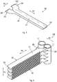
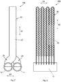
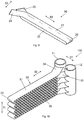
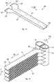
- Wärmetauscher (100), der aufweist:einen ersten Verteiler (11) und einen zweiten Verteiler (12), die auf der gleichen Seite des Wärmetauschers (100) angeordnet sind; undeine Vielzahl von flachen Wärmetauscherrohren (20), wobei jedes Wärmetauscherrohr (20) aufweist:einen ersten Wärmetauscherteil (21) und einen zweiten Wärmetauscherteil (22), die im Wesentlichen parallel sind; undein erstes Ende (24) und ein zweites Ende (25), die mit dem ersten Wärmetauscherteil (21) bzw. dem zweiten Wärmetauscherteil (22) verbunden sind, wobei das erste Ende (24) durch Krümmung von einer Mittellinie des ersten Wärmetauscherteils (21) abweicht, so dass das erste Ende (24) und das zweite Ende (25) mit dem ersten Verteiler (11) bzw. dem zweiten Verteiler (12) verbunden sind und in Fluidverbindung mit diesen stehen,der erste Wärmetauscherteil (21) und der zweite Wärmetauscherteil (22) in einer ersten Richtung (D1) angeordnet sind und sich in einer zweiten Richtung (D2) erstrecken, die im Wesentlichen senkrecht zu der ersten Richtung (D1) ist, unddie gleiche Seite des Wärmetauschers (100) in einer Ebene, die durch die erste Richtung (D1) und die zweite Richtung (D2) definiert ist, die gleiche Seite in der zweiten Richtung (D2) ist, dadurch gekennzeichnet, dass jedes Wärmetauscherrohr (20) weiterhin einen Verbindungsteil (23) aufweist, der den ersten Wärmetauscherteil (21) und den zweiten Wärmetauscherteil (22) verbindet; wobei mindestens einer der Verbindungsteile (23) ein U-förmiges Rohr ist oder mindestens ein Wärmetauscherrohr (20) ein integrales Ganzes ist und der Verbindungsteil (23) des mindestens einen Wärmetauscherrohrs (20) durch Biegen gebildet ist, wobei Rippen (30) zwischen dem ersten Wärmetauscherteil (21) und dem zweiten Wärmetauscherteil (22) angeordnet sind.
- Wärmetauscher nach Anspruch 1, dadurch gekennzeichnet, dass:
das zweite Ende (25) von einer Mittellinie des zweiten Wärmetauscherteils (22) durch Krümmung abweicht und das erste Ende (24) und das zweite Ende (25) in entgegengesetzte Richtungen abweichen. - Wärmetauscher nach Anspruch 1, dadurch gekennzeichnet, dass der erste Wärmetauscherteil (21) und der zweite Wärmetauscherteil (22) in einer ersten Richtung (D1) angeordnet sind und sich in einer zweiten Richtung (D2) erstrecken, die im Wesentlichen senkrecht zur ersten Richtung (D1) ist, und das erste Ende (24) von der Mittellinie des ersten Wärmetauscherteils (21) in einer dritten Richtung (D3) abweicht, die im Wesentlichen senkrecht zu der ersten Richtung (D1) und der zweiten Richtung (D2) ist.
- Wärmetauscher nach Anspruch 2, dadurch gekennzeichnet, dass der erste Wärmetauscherteil (21) und der zweite Wärmetauscherteil (22) in einer ersten Richtung (D1) angeordnet sind und sich in einer zweiten Richtung (D2) erstrecken, die im Wesentlichen senkrecht zu der ersten Richtung (D1) ist, wobei das erste Ende von der Mittellinie des ersten Wärmetauscherteils (21) in eine dritte Richtung (D3) abweicht, die im Wesentlichen senkrecht zu der ersten Richtung (D1) und der zweiten Richtung (D2) ist, und das zweite Ende (25) von der Mittellinie des zweiten Wärmetauscherteils (22) in eine dritte Richtung (D3) abweicht, die im Wesentlichen senkrecht zu der ersten Richtung (D1) und der zweiten Richtung (D2) ist.
- Wärmetauscher nach Anspruch 1, dadurch gekennzeichnet, dass jedes Wärmetauscherrohr (20) weiterhin eine Vielzahl von dritten Wärmetauscherteilen aufweist, die zwischen dem ersten Wärmetauscherteil (21) und dem zweiten Wärmetauscherteil (22) angeordnet sind, und das erste Wärmetauscherteil (21), das zweite Wärmetauscherteil (22) und das dritte Wärmetauscherteil im Wesentlichen parallel sind.
- Wärmetauscher nach Anspruch 5, dadurch gekennzeichnet, dass jedes Wärmetauscherrohr (20) weiterhin eine Vielzahl von Verbindungsteilen (23) aufweist, die benachbarte Wärmetauscherteile zwischen dem ersten Wärmetauscherteil (21), dem dritten Wärmetauscherteil und dem zweiten Wärmetauscherteil (22) verbinden, wobei mindestens eines der Verbindungsteile (23) durch Biegen gebildet ist oder ein U-förmiges Rohr ist.
- Wärmetauscher nach Anspruch 1, weiter gekennzeichnet durch eine Rippe (30), die zwischen dem ersten Wärmetauscherteil (21) und dem zweiten Wärmetauscherteil (22) angeordnet ist.
- Wärmetauscher nach Anspruch 5, weiter gekennzeichnet durch eine Rippe (30), die zwischen benachbarten Wärmetauscherteilen unter dem ersten Wärmetauscherteil (21), den dritten Wärmetauscherteilen und dem zweiten Wärmetauscherteil (22) angeordnet ist.
- Wärmetauscher nach Anspruch 1, dadurch gekennzeichnet, dass das erste Ende (24) jedes Wärmetauscherrohrs (20) relativ zum ersten Wärmetauscherteil (21) geneigt ist.
- Wärmetauscher nach Anspruch 2, dadurch gekennzeichnet, dass das erste Ende (24) jedes Wärmetauscherrohrs relativ zu dem ersten Wärmetauscherteil (21) geneigt ist und das zweite Ende (25) jedes Wärmetauscherrohrs relativ zu dem zweiten Wärmetauscherteil (22) geneigt ist.
- Wärmetauscher nach Anspruch 3, dadurch gekennzeichnet, dass das erste Ende (24) von der Mittellinie des ersten Wärmetauscherteils (21) abweicht durch Krümmung im Wesentlichen in einer Ebene, die durch die zweite Richtung (D2) und die dritte Richtung (D3) definiert ist.
- Wärmetauscher nach Anspruch 4, dadurch gekennzeichnet, dass das erste Ende (24) von der Mittellinie des ersten Wärmetauscherteils (21) abweicht durch Krümmung im Wesentlichen in einer Ebene, die durch die zweite Richtung (D2) und die dritte Richtung (D3) definiert ist, und das zweite Ende (25) von der Mittellinie des zweiten Wärmetauschers (22) abweicht durch Krümmung im Wesentlichen in der Ebene, die durch die zweite Richtung (D2) und die dritte Richtung (D3) definiert ist.
- Wärmetauscher nach Anspruch 3, dadurch gekennzeichnet, dass das erste Ende (24) und der erste Wärmetauscherteil (21) jedes Wärmetauscherrohrs (20) im Wesentlichen in einer Ebene liegen, die durch die zweite Richtung (D2) und die dritte Richtung (D3) definiert ist.
- Wärmetauscher nach Anspruch 4, dadurch gekennzeichnet, dass das erste Ende (24) und der erste Wärmetauscherteil (21) jedes Wärmetauscherrohrs (20) im Wesentlichen in einer Ebene liegen, die durch die zweite Richtung (D2) und die dritte Richtung (D3) definiert ist, und das zweite Ende (25) und der zweite Wärmetauscherteil (22) jedes Wärmetauscherrohrs (20) im Wesentlichen in der Ebene liegen, die durch die zweite Richtung (D2) und die dritte Richtung (D3) definiert ist.
- Wärmetauscher nach Anspruch 1, dadurch gekennzeichnet, dass der erste Verteiler (11) und der zweite Verteiler (12) Verteiler (11, 12) mit D-förmigen Querschnitten sind, und die im Wesentlichen flachen Oberflächen der Verteiler (11, 12) mit D-förmigen Querschnitten einander zugewandt sind.
- Wärmetauscher nach Anspruch 1 oder 15, weiter gekennzeichnet durch ein wärmeisolierendes Element (40), das zwischen dem ersten Verteiler (11) und dem zweiten Verteiler (12) angeordnet ist.
- Wärmetauscher nach Anspruch 1, dadurch gekennzeichnet, jedes der Wärmetauscherrohre (20) ein integrales Ganzes ist.
Applications Claiming Priority (2)
| Application Number | Priority Date | Filing Date | Title |
|---|---|---|---|
| CN201510711462.9A CN106642826B (zh) | 2015-10-28 | 2015-10-28 | 换热器 |
| PCT/CN2016/093023 WO2017071355A1 (zh) | 2015-10-28 | 2016-08-03 | 换热器 |
Publications (3)
| Publication Number | Publication Date |
|---|---|
| EP3370019A1 EP3370019A1 (de) | 2018-09-05 |
| EP3370019A4 EP3370019A4 (de) | 2019-06-26 |
| EP3370019B1 true EP3370019B1 (de) | 2020-06-17 |
Family
ID=58631279
Family Applications (1)
| Application Number | Title | Priority Date | Filing Date |
|---|---|---|---|
| EP16858794.7A Active EP3370019B1 (de) | 2015-10-28 | 2016-08-03 | Wärmetauscher |
Country Status (6)
| Country | Link |
|---|---|
| US (1) | US20180340746A1 (de) |
| EP (1) | EP3370019B1 (de) |
| JP (1) | JP7125344B2 (de) |
| KR (1) | KR102520736B1 (de) |
| CN (1) | CN106642826B (de) |
| WO (1) | WO2017071355A1 (de) |
Families Citing this family (6)
| Publication number | Priority date | Publication date | Assignee | Title |
|---|---|---|---|---|
| CN109900144B (zh) * | 2017-12-08 | 2021-03-16 | 丹佛斯微通道换热器(嘉兴)有限公司 | 换热器和具有该换热器的换热装置 |
| US20190368819A1 (en) * | 2018-05-30 | 2019-12-05 | Johnson Controls Technology Company | Heat exchanger for hvac unit |
| CN111322795A (zh) | 2018-12-14 | 2020-06-23 | 丹佛斯有限公司 | 换热器和空调系统 |
| EP4242556A1 (de) * | 2020-11-03 | 2023-09-13 | Danfoss A/S | Wärmetauscher und klimaanlage damit |
| US20220221226A1 (en) * | 2021-01-13 | 2022-07-14 | Mahle International Gmbh | Flat tube and heat exchanger |
| US20220252349A1 (en) | 2021-02-11 | 2022-08-11 | Mahle International Gmbh | Heat exchanger |
Family Cites Families (23)
| Publication number | Priority date | Publication date | Assignee | Title |
|---|---|---|---|---|
| JP3305460B2 (ja) * | 1993-11-24 | 2002-07-22 | 昭和電工株式会社 | 熱交換器 |
| DE19830863A1 (de) * | 1998-07-10 | 2000-01-13 | Behr Gmbh & Co | Flachrohr mit Querversatz-Umkehrbogenabschnitt und damit aufgebauter Wärmeübertrager |
| ATE193371T1 (de) * | 1998-09-03 | 2000-06-15 | Genebrev Sa | Radiator für heizungsanlage mit flüssigkeitsumlauf |
| KR20040105439A (ko) * | 2003-06-09 | 2004-12-16 | 한라공조주식회사 | 이산화탄소용 열교환기 |
| EP1844285A4 (de) * | 2005-02-02 | 2011-12-21 | Carrier Corp | Mehrkanal-flachrohr-wärmetauscher |
| FR2890730B1 (fr) | 2005-09-13 | 2007-10-19 | Valeo Systemes Thermiques | Element de circuit a tubes plats, et echangeur de chaleur muni de tels elements |
| CN101432590B (zh) * | 2006-04-14 | 2012-01-25 | 三菱电机株式会社 | 热交换器及制冷空调装置 |
| FR2899959B1 (fr) * | 2006-04-14 | 2008-08-08 | Valeo Systemes Thermiques | Echangeur de chaleur ameliore et module d'echange de chaleur comportant un tel echangeur |
| DE102006033771A1 (de) * | 2006-07-21 | 2008-01-24 | Modine Manufacturing Co., Racine | Wärmetauscher |
| TWI361880B (en) * | 2008-11-17 | 2012-04-11 | Heat exchanging module and working fluid distributor thereof and method for manufacturing heat exchange module | |
| JP2010169289A (ja) * | 2009-01-21 | 2010-08-05 | Nikkei Nekko Kk | 屈曲状熱交換器及びその製造方法 |
| CN101846465B (zh) * | 2010-04-13 | 2011-11-09 | 三花丹佛斯(杭州)微通道换热器有限公司 | 换热器 |
| JP5796564B2 (ja) * | 2011-11-30 | 2015-10-21 | 株式会社デンソー | 熱交換器 |
| JP5884530B2 (ja) * | 2012-02-03 | 2016-03-15 | 富士通株式会社 | ラジエータ及びそれを備えた電子機器 |
| EP2948724B1 (de) * | 2013-01-28 | 2019-05-29 | Carrier Corporation | Wärmetauschereinheit mit mehreren rohrbündeln und einer verteileranordnung |
| WO2014146505A1 (zh) * | 2013-03-21 | 2014-09-25 | 杭州三花微通道换热器有限公司 | 折弯式换热器及其制造方法 |
| CN203310165U (zh) * | 2013-05-14 | 2013-11-27 | 广东美的制冷设备有限公司 | 平行流换热器及空调器 |
| CN103277942B (zh) * | 2013-05-14 | 2015-06-03 | 广东美的制冷设备有限公司 | 平行流换热器及空调器 |
| CN103245132B (zh) * | 2013-05-29 | 2015-09-23 | 上海交通大学 | 有利于减少制冷剂充注量的微通道换热器 |
| CN104596153B (zh) * | 2013-10-31 | 2018-09-28 | 杭州三花微通道换热器有限公司 | 微通道换热器 |
| CN103697745A (zh) * | 2014-01-20 | 2014-04-02 | 丹佛斯微通道换热器(嘉兴)有限公司 | 集流管组件以及具有该集流管组件的换热器 |
| DE102014206612A1 (de) * | 2014-04-04 | 2015-10-29 | Mahle International Gmbh | Wärmetauscher |
| CN204188033U (zh) * | 2014-09-29 | 2015-03-04 | 杭州三花微通道换热器有限公司 | 一种换热器 |
-
2015
- 2015-10-28 CN CN201510711462.9A patent/CN106642826B/zh active Active
-
2016
- 2016-08-03 EP EP16858794.7A patent/EP3370019B1/de active Active
- 2016-08-03 WO PCT/CN2016/093023 patent/WO2017071355A1/zh active Application Filing
- 2016-08-03 US US15/771,539 patent/US20180340746A1/en not_active Abandoned
- 2016-08-03 JP JP2018521359A patent/JP7125344B2/ja active Active
- 2016-08-03 KR KR1020187013851A patent/KR102520736B1/ko active IP Right Grant
Non-Patent Citations (1)
| Title |
|---|
| None * |
Also Published As
| Publication number | Publication date |
|---|---|
| US20180340746A1 (en) | 2018-11-29 |
| CN106642826A (zh) | 2017-05-10 |
| WO2017071355A1 (zh) | 2017-05-04 |
| CN106642826B (zh) | 2019-04-19 |
| KR20180077188A (ko) | 2018-07-06 |
| EP3370019A1 (de) | 2018-09-05 |
| JP7125344B2 (ja) | 2022-08-24 |
| KR102520736B1 (ko) | 2023-04-11 |
| EP3370019A4 (de) | 2019-06-26 |
| JP2018532093A (ja) | 2018-11-01 |
Similar Documents
| Publication | Publication Date | Title |
|---|---|---|
| EP3370019B1 (de) | Wärmetauscher | |
| EP2930456B1 (de) | Flachrohrwärmeaustauscher und ausseneinheit für klimaanlage damit | |
| CN103925826A (zh) | 热交换器用管 | |
| US20140131022A1 (en) | Heat exchanger utilizing tubular structures having internal flow altering members and external chamber assemblies | |
| CN105452796A (zh) | 换热器用散热片 | |
| JP2015017776A5 (de) | ||
| WO2015106726A1 (zh) | 集流管组件以及具有该集流管组件的换热器 | |
| US20130240177A1 (en) | Nested heat exchanger | |
| US20190195572A1 (en) | Heat exchanger | |
| EP2962055B1 (de) | Rippenlösung im zusammenhang mit auf mikrokanal basierendem wärmetauscher | |
| CN104089517A (zh) | 用于换热器的翅片和具有该翅片的换热器 | |
| CN105737453B (zh) | 冷却装置及其使用方法 | |
| CN211855020U (zh) | 换热管和具有其的换热器 | |
| JP2016148480A (ja) | 熱交換器 | |
| EP3224565B1 (de) | Frosttoleranter mikrokanalwärmetauscher | |
| JP7044969B2 (ja) | 熱交換器 | |
| US20170321969A1 (en) | Fin for a finned pack for heat exchangers, as well as heat exchanger | |
| US10830542B2 (en) | Method for manufacturing a multiple manifold assembly having internal communication ports | |
| JP5591285B2 (ja) | 熱交換器および空気調和機 | |
| EP3141862B1 (de) | Integrierte dichtungsvorrichtung und wärmetauscher damit | |
| JP2015535591A (ja) | 熱交換手段のチューブ要素 | |
| US9453599B2 (en) | Bi-channel coolant tube having crossover channels to allow coolant interaction | |
| EP3572743B1 (de) | Wärmetauscherbaugruppe | |
| WO2013105490A1 (ja) | 熱交換器 | |
| JP6583729B2 (ja) | 熱交換器 |
Legal Events
| Date | Code | Title | Description |
|---|---|---|---|
| STAA | Information on the status of an ep patent application or granted ep patent |
Free format text: STATUS: THE INTERNATIONAL PUBLICATION HAS BEEN MADE |
|
| PUAI | Public reference made under article 153(3) epc to a published international application that has entered the european phase |
Free format text: ORIGINAL CODE: 0009012 |
|
| STAA | Information on the status of an ep patent application or granted ep patent |
Free format text: STATUS: REQUEST FOR EXAMINATION WAS MADE |
|
| 17P | Request for examination filed |
Effective date: 20180426 |
|
| AK | Designated contracting states |
Kind code of ref document: A1 Designated state(s): AL AT BE BG CH CY CZ DE DK EE ES FI FR GB GR HR HU IE IS IT LI LT LU LV MC MK MT NL NO PL PT RO RS SE SI SK SM TR |
|
| AX | Request for extension of the european patent |
Extension state: BA ME |
|
| DAV | Request for validation of the european patent (deleted) | ||
| DAX | Request for extension of the european patent (deleted) | ||
| A4 | Supplementary search report drawn up and despatched |
Effective date: 20190527 |
|
| RIC1 | Information provided on ipc code assigned before grant |
Ipc: F28F 9/02 20060101ALI20190521BHEP Ipc: F28D 1/047 20060101ALI20190521BHEP Ipc: F28D 21/00 20060101ALI20190521BHEP Ipc: F28F 1/02 20060101ALI20190521BHEP Ipc: F25B 39/00 20060101AFI20190521BHEP |
|
| GRAP | Despatch of communication of intention to grant a patent |
Free format text: ORIGINAL CODE: EPIDOSNIGR1 |
|
| STAA | Information on the status of an ep patent application or granted ep patent |
Free format text: STATUS: GRANT OF PATENT IS INTENDED |
|
| INTG | Intention to grant announced |
Effective date: 20200131 |
|
| GRAS | Grant fee paid |
Free format text: ORIGINAL CODE: EPIDOSNIGR3 |
|
| GRAA | (expected) grant |
Free format text: ORIGINAL CODE: 0009210 |
|
| STAA | Information on the status of an ep patent application or granted ep patent |
Free format text: STATUS: THE PATENT HAS BEEN GRANTED |
|
| AK | Designated contracting states |
Kind code of ref document: B1 Designated state(s): AL AT BE BG CH CY CZ DE DK EE ES FI FR GB GR HR HU IE IS IT LI LT LU LV MC MK MT NL NO PL PT RO RS SE SI SK SM TR |
|
| REG | Reference to a national code |
Ref country code: GB Ref legal event code: FG4D |
|
| REG | Reference to a national code |
Ref country code: CH Ref legal event code: EP |
|
| REG | Reference to a national code |
Ref country code: IE Ref legal event code: FG4D |
|
| REG | Reference to a national code |
Ref country code: DE Ref legal event code: R096 Ref document number: 602016038480 Country of ref document: DE |
|
| REG | Reference to a national code |
Ref country code: AT Ref legal event code: REF Ref document number: 1281789 Country of ref document: AT Kind code of ref document: T Effective date: 20200715 |
|
| PG25 | Lapsed in a contracting state [announced via postgrant information from national office to epo] |
Ref country code: FI Free format text: LAPSE BECAUSE OF FAILURE TO SUBMIT A TRANSLATION OF THE DESCRIPTION OR TO PAY THE FEE WITHIN THE PRESCRIBED TIME-LIMIT Effective date: 20200617 Ref country code: GR Free format text: LAPSE BECAUSE OF FAILURE TO SUBMIT A TRANSLATION OF THE DESCRIPTION OR TO PAY THE FEE WITHIN THE PRESCRIBED TIME-LIMIT Effective date: 20200918 Ref country code: NO Free format text: LAPSE BECAUSE OF FAILURE TO SUBMIT A TRANSLATION OF THE DESCRIPTION OR TO PAY THE FEE WITHIN THE PRESCRIBED TIME-LIMIT Effective date: 20200917 Ref country code: SE Free format text: LAPSE BECAUSE OF FAILURE TO SUBMIT A TRANSLATION OF THE DESCRIPTION OR TO PAY THE FEE WITHIN THE PRESCRIBED TIME-LIMIT Effective date: 20200617 Ref country code: LT Free format text: LAPSE BECAUSE OF FAILURE TO SUBMIT A TRANSLATION OF THE DESCRIPTION OR TO PAY THE FEE WITHIN THE PRESCRIBED TIME-LIMIT Effective date: 20200617 |
|
| REG | Reference to a national code |
Ref country code: LT Ref legal event code: MG4D |
|
| REG | Reference to a national code |
Ref country code: NL Ref legal event code: MP Effective date: 20200617 |
|
| PG25 | Lapsed in a contracting state [announced via postgrant information from national office to epo] |
Ref country code: RS Free format text: LAPSE BECAUSE OF FAILURE TO SUBMIT A TRANSLATION OF THE DESCRIPTION OR TO PAY THE FEE WITHIN THE PRESCRIBED TIME-LIMIT Effective date: 20200617 Ref country code: BG Free format text: LAPSE BECAUSE OF FAILURE TO SUBMIT A TRANSLATION OF THE DESCRIPTION OR TO PAY THE FEE WITHIN THE PRESCRIBED TIME-LIMIT Effective date: 20200917 Ref country code: LV Free format text: LAPSE BECAUSE OF FAILURE TO SUBMIT A TRANSLATION OF THE DESCRIPTION OR TO PAY THE FEE WITHIN THE PRESCRIBED TIME-LIMIT Effective date: 20200617 Ref country code: HR Free format text: LAPSE BECAUSE OF FAILURE TO SUBMIT A TRANSLATION OF THE DESCRIPTION OR TO PAY THE FEE WITHIN THE PRESCRIBED TIME-LIMIT Effective date: 20200617 |
|
| REG | Reference to a national code |
Ref country code: AT Ref legal event code: MK05 Ref document number: 1281789 Country of ref document: AT Kind code of ref document: T Effective date: 20200617 |
|
| PG25 | Lapsed in a contracting state [announced via postgrant information from national office to epo] |
Ref country code: AL Free format text: LAPSE BECAUSE OF FAILURE TO SUBMIT A TRANSLATION OF THE DESCRIPTION OR TO PAY THE FEE WITHIN THE PRESCRIBED TIME-LIMIT Effective date: 20200617 Ref country code: NL Free format text: LAPSE BECAUSE OF FAILURE TO SUBMIT A TRANSLATION OF THE DESCRIPTION OR TO PAY THE FEE WITHIN THE PRESCRIBED TIME-LIMIT Effective date: 20200617 |
|
| PG25 | Lapsed in a contracting state [announced via postgrant information from national office to epo] |
Ref country code: ES Free format text: LAPSE BECAUSE OF FAILURE TO SUBMIT A TRANSLATION OF THE DESCRIPTION OR TO PAY THE FEE WITHIN THE PRESCRIBED TIME-LIMIT Effective date: 20200617 Ref country code: IT Free format text: LAPSE BECAUSE OF FAILURE TO SUBMIT A TRANSLATION OF THE DESCRIPTION OR TO PAY THE FEE WITHIN THE PRESCRIBED TIME-LIMIT Effective date: 20200617 Ref country code: SM Free format text: LAPSE BECAUSE OF FAILURE TO SUBMIT A TRANSLATION OF THE DESCRIPTION OR TO PAY THE FEE WITHIN THE PRESCRIBED TIME-LIMIT Effective date: 20200617 Ref country code: AT Free format text: LAPSE BECAUSE OF FAILURE TO SUBMIT A TRANSLATION OF THE DESCRIPTION OR TO PAY THE FEE WITHIN THE PRESCRIBED TIME-LIMIT Effective date: 20200617 Ref country code: EE Free format text: LAPSE BECAUSE OF FAILURE TO SUBMIT A TRANSLATION OF THE DESCRIPTION OR TO PAY THE FEE WITHIN THE PRESCRIBED TIME-LIMIT Effective date: 20200617 Ref country code: RO Free format text: LAPSE BECAUSE OF FAILURE TO SUBMIT A TRANSLATION OF THE DESCRIPTION OR TO PAY THE FEE WITHIN THE PRESCRIBED TIME-LIMIT Effective date: 20200617 Ref country code: CZ Free format text: LAPSE BECAUSE OF FAILURE TO SUBMIT A TRANSLATION OF THE DESCRIPTION OR TO PAY THE FEE WITHIN THE PRESCRIBED TIME-LIMIT Effective date: 20200617 Ref country code: PT Free format text: LAPSE BECAUSE OF FAILURE TO SUBMIT A TRANSLATION OF THE DESCRIPTION OR TO PAY THE FEE WITHIN THE PRESCRIBED TIME-LIMIT Effective date: 20201019 |
|
| PG25 | Lapsed in a contracting state [announced via postgrant information from national office to epo] |
Ref country code: PL Free format text: LAPSE BECAUSE OF FAILURE TO SUBMIT A TRANSLATION OF THE DESCRIPTION OR TO PAY THE FEE WITHIN THE PRESCRIBED TIME-LIMIT Effective date: 20200617 Ref country code: SK Free format text: LAPSE BECAUSE OF FAILURE TO SUBMIT A TRANSLATION OF THE DESCRIPTION OR TO PAY THE FEE WITHIN THE PRESCRIBED TIME-LIMIT Effective date: 20200617 Ref country code: IS Free format text: LAPSE BECAUSE OF FAILURE TO SUBMIT A TRANSLATION OF THE DESCRIPTION OR TO PAY THE FEE WITHIN THE PRESCRIBED TIME-LIMIT Effective date: 20201017 |
|
| REG | Reference to a national code |
Ref country code: DE Ref legal event code: R097 Ref document number: 602016038480 Country of ref document: DE |
|
| PG25 | Lapsed in a contracting state [announced via postgrant information from national office to epo] |
Ref country code: MC Free format text: LAPSE BECAUSE OF FAILURE TO SUBMIT A TRANSLATION OF THE DESCRIPTION OR TO PAY THE FEE WITHIN THE PRESCRIBED TIME-LIMIT Effective date: 20200617 |
|
| REG | Reference to a national code |
Ref country code: CH Ref legal event code: PL |
|
| PLBE | No opposition filed within time limit |
Free format text: ORIGINAL CODE: 0009261 |
|
| STAA | Information on the status of an ep patent application or granted ep patent |
Free format text: STATUS: NO OPPOSITION FILED WITHIN TIME LIMIT |
|
| PG25 | Lapsed in a contracting state [announced via postgrant information from national office to epo] |
Ref country code: CH Free format text: LAPSE BECAUSE OF NON-PAYMENT OF DUE FEES Effective date: 20200831 Ref country code: DK Free format text: LAPSE BECAUSE OF FAILURE TO SUBMIT A TRANSLATION OF THE DESCRIPTION OR TO PAY THE FEE WITHIN THE PRESCRIBED TIME-LIMIT Effective date: 20200617 Ref country code: LU Free format text: LAPSE BECAUSE OF NON-PAYMENT OF DUE FEES Effective date: 20200803 Ref country code: LI Free format text: LAPSE BECAUSE OF NON-PAYMENT OF DUE FEES Effective date: 20200831 |
|
| 26N | No opposition filed |
Effective date: 20210318 |
|
| GBPC | Gb: european patent ceased through non-payment of renewal fee |
Effective date: 20200917 |
|
| REG | Reference to a national code |
Ref country code: BE Ref legal event code: MM Effective date: 20200831 |
|
| PG25 | Lapsed in a contracting state [announced via postgrant information from national office to epo] |
Ref country code: SI Free format text: LAPSE BECAUSE OF FAILURE TO SUBMIT A TRANSLATION OF THE DESCRIPTION OR TO PAY THE FEE WITHIN THE PRESCRIBED TIME-LIMIT Effective date: 20200617 |
|
| PG25 | Lapsed in a contracting state [announced via postgrant information from national office to epo] |
Ref country code: FR Free format text: LAPSE BECAUSE OF NON-PAYMENT OF DUE FEES Effective date: 20200817 |
|
| PG25 | Lapsed in a contracting state [announced via postgrant information from national office to epo] |
Ref country code: GB Free format text: LAPSE BECAUSE OF NON-PAYMENT OF DUE FEES Effective date: 20200917 Ref country code: IE Free format text: LAPSE BECAUSE OF NON-PAYMENT OF DUE FEES Effective date: 20200803 Ref country code: BE Free format text: LAPSE BECAUSE OF NON-PAYMENT OF DUE FEES Effective date: 20200831 |
|
| PG25 | Lapsed in a contracting state [announced via postgrant information from national office to epo] |
Ref country code: TR Free format text: LAPSE BECAUSE OF FAILURE TO SUBMIT A TRANSLATION OF THE DESCRIPTION OR TO PAY THE FEE WITHIN THE PRESCRIBED TIME-LIMIT Effective date: 20200617 Ref country code: MT Free format text: LAPSE BECAUSE OF FAILURE TO SUBMIT A TRANSLATION OF THE DESCRIPTION OR TO PAY THE FEE WITHIN THE PRESCRIBED TIME-LIMIT Effective date: 20200617 Ref country code: CY Free format text: LAPSE BECAUSE OF FAILURE TO SUBMIT A TRANSLATION OF THE DESCRIPTION OR TO PAY THE FEE WITHIN THE PRESCRIBED TIME-LIMIT Effective date: 20200617 |
|
| PG25 | Lapsed in a contracting state [announced via postgrant information from national office to epo] |
Ref country code: MK Free format text: LAPSE BECAUSE OF FAILURE TO SUBMIT A TRANSLATION OF THE DESCRIPTION OR TO PAY THE FEE WITHIN THE PRESCRIBED TIME-LIMIT Effective date: 20200617 |
|
| P01 | Opt-out of the competence of the unified patent court (upc) registered |
Effective date: 20230621 |
|
| PGFP | Annual fee paid to national office [announced via postgrant information from national office to epo] |
Ref country code: DE Payment date: 20230705 Year of fee payment: 8 |