EP3369882B2 - Chain drive and chain station - Google Patents
Chain drive and chain station Download PDFInfo
- Publication number
- EP3369882B2 EP3369882B2 EP18159719.6A EP18159719A EP3369882B2 EP 3369882 B2 EP3369882 B2 EP 3369882B2 EP 18159719 A EP18159719 A EP 18159719A EP 3369882 B2 EP3369882 B2 EP 3369882B2
- Authority
- EP
- European Patent Office
- Prior art keywords
- chain
- guide
- thrust
- straight
- station
- Prior art date
- Legal status (The legal status is an assumption and is not a legal conclusion. Google has not performed a legal analysis and makes no representation as to the accuracy of the status listed.)
- Active
Links
- 239000011800 void material Substances 0.000 claims 3
- 230000002349 favourable effect Effects 0.000 description 3
- 238000005452 bending Methods 0.000 description 2
- 238000005516 engineering process Methods 0.000 description 2
- 238000000034 method Methods 0.000 description 2
- 230000005540 biological transmission Effects 0.000 description 1
- 238000000605 extraction Methods 0.000 description 1
- 239000011521 glass Substances 0.000 description 1
- 238000009434 installation Methods 0.000 description 1
- 239000002184 metal Substances 0.000 description 1
- 238000012986 modification Methods 0.000 description 1
- 230000004048 modification Effects 0.000 description 1
- 239000003380 propellant Substances 0.000 description 1
- 239000000779 smoke Substances 0.000 description 1
- 238000009423 ventilation Methods 0.000 description 1
Images


Classifications
-
- E—FIXED CONSTRUCTIONS
- E05—LOCKS; KEYS; WINDOW OR DOOR FITTINGS; SAFES
- E05F—DEVICES FOR MOVING WINGS INTO OPEN OR CLOSED POSITION; CHECKS FOR WINGS; WING FITTINGS NOT OTHERWISE PROVIDED FOR, CONCERNED WITH THE FUNCTIONING OF THE WING
- E05F11/00—Man-operated mechanisms for operating wings, including those which also operate the fastening
- E05F11/02—Man-operated mechanisms for operating wings, including those which also operate the fastening for wings in general, e.g. fanlights
- E05F11/04—Man-operated mechanisms for operating wings, including those which also operate the fastening for wings in general, e.g. fanlights with cords, chains or cables
- E05F11/06—Man-operated mechanisms for operating wings, including those which also operate the fastening for wings in general, e.g. fanlights with cords, chains or cables in guide-channels
-
- E—FIXED CONSTRUCTIONS
- E05—LOCKS; KEYS; WINDOW OR DOOR FITTINGS; SAFES
- E05F—DEVICES FOR MOVING WINGS INTO OPEN OR CLOSED POSITION; CHECKS FOR WINGS; WING FITTINGS NOT OTHERWISE PROVIDED FOR, CONCERNED WITH THE FUNCTIONING OF THE WING
- E05F15/00—Power-operated mechanisms for wings
- E05F15/60—Power-operated mechanisms for wings using electrical actuators
- E05F15/603—Power-operated mechanisms for wings using electrical actuators using rotary electromotors
- E05F15/611—Power-operated mechanisms for wings using electrical actuators using rotary electromotors for swinging wings
- E05F15/616—Power-operated mechanisms for wings using electrical actuators using rotary electromotors for swinging wings operated by push-pull mechanisms
- E05F15/619—Power-operated mechanisms for wings using electrical actuators using rotary electromotors for swinging wings operated by push-pull mechanisms using flexible or rigid rack-and-pinion arrangements
-
- F—MECHANICAL ENGINEERING; LIGHTING; HEATING; WEAPONS; BLASTING
- F16—ENGINEERING ELEMENTS AND UNITS; GENERAL MEASURES FOR PRODUCING AND MAINTAINING EFFECTIVE FUNCTIONING OF MACHINES OR INSTALLATIONS; THERMAL INSULATION IN GENERAL
- F16G—BELTS, CABLES, OR ROPES, PREDOMINANTLY USED FOR DRIVING PURPOSES; CHAINS; FITTINGS PREDOMINANTLY USED THEREFOR
- F16G13/00—Chains
- F16G13/18—Chains having special overall characteristics
- F16G13/20—Chains having special overall characteristics stiff; Push-pull chains
-
- E—FIXED CONSTRUCTIONS
- E05—LOCKS; KEYS; WINDOW OR DOOR FITTINGS; SAFES
- E05Y—INDEXING SCHEME ASSOCIATED WITH SUBCLASSES E05D AND E05F, RELATING TO CONSTRUCTION ELEMENTS, ELECTRIC CONTROL, POWER SUPPLY, POWER SIGNAL OR TRANSMISSION, USER INTERFACES, MOUNTING OR COUPLING, DETAILS, ACCESSORIES, AUXILIARY OPERATIONS NOT OTHERWISE PROVIDED FOR, APPLICATION THEREOF
- E05Y2201/00—Constructional elements; Accessories therefor
- E05Y2201/10—Covers; Housings
-
- E—FIXED CONSTRUCTIONS
- E05—LOCKS; KEYS; WINDOW OR DOOR FITTINGS; SAFES
- E05Y—INDEXING SCHEME ASSOCIATED WITH SUBCLASSES E05D AND E05F, RELATING TO CONSTRUCTION ELEMENTS, ELECTRIC CONTROL, POWER SUPPLY, POWER SIGNAL OR TRANSMISSION, USER INTERFACES, MOUNTING OR COUPLING, DETAILS, ACCESSORIES, AUXILIARY OPERATIONS NOT OTHERWISE PROVIDED FOR, APPLICATION THEREOF
- E05Y2201/00—Constructional elements; Accessories therefor
- E05Y2201/60—Suspension or transmission members; Accessories therefor
- E05Y2201/622—Suspension or transmission members elements
- E05Y2201/644—Flexible elongated pulling elements
- E05Y2201/656—Chains
-
- E—FIXED CONSTRUCTIONS
- E05—LOCKS; KEYS; WINDOW OR DOOR FITTINGS; SAFES
- E05Y—INDEXING SCHEME ASSOCIATED WITH SUBCLASSES E05D AND E05F, RELATING TO CONSTRUCTION ELEMENTS, ELECTRIC CONTROL, POWER SUPPLY, POWER SIGNAL OR TRANSMISSION, USER INTERFACES, MOUNTING OR COUPLING, DETAILS, ACCESSORIES, AUXILIARY OPERATIONS NOT OTHERWISE PROVIDED FOR, APPLICATION THEREOF
- E05Y2201/00—Constructional elements; Accessories therefor
- E05Y2201/60—Suspension or transmission members; Accessories therefor
- E05Y2201/622—Suspension or transmission members elements
- E05Y2201/658—Members cooperating with flexible elongated pulling elements
- E05Y2201/66—Deflectors; Guides
-
- E—FIXED CONSTRUCTIONS
- E05—LOCKS; KEYS; WINDOW OR DOOR FITTINGS; SAFES
- E05Y—INDEXING SCHEME ASSOCIATED WITH SUBCLASSES E05D AND E05F, RELATING TO CONSTRUCTION ELEMENTS, ELECTRIC CONTROL, POWER SUPPLY, POWER SIGNAL OR TRANSMISSION, USER INTERFACES, MOUNTING OR COUPLING, DETAILS, ACCESSORIES, AUXILIARY OPERATIONS NOT OTHERWISE PROVIDED FOR, APPLICATION THEREOF
- E05Y2201/00—Constructional elements; Accessories therefor
- E05Y2201/60—Suspension or transmission members; Accessories therefor
- E05Y2201/622—Suspension or transmission members elements
- E05Y2201/658—Members cooperating with flexible elongated pulling elements
- E05Y2201/668—Pulleys; Wheels
-
- E—FIXED CONSTRUCTIONS
- E05—LOCKS; KEYS; WINDOW OR DOOR FITTINGS; SAFES
- E05Y—INDEXING SCHEME ASSOCIATED WITH SUBCLASSES E05D AND E05F, RELATING TO CONSTRUCTION ELEMENTS, ELECTRIC CONTROL, POWER SUPPLY, POWER SIGNAL OR TRANSMISSION, USER INTERFACES, MOUNTING OR COUPLING, DETAILS, ACCESSORIES, AUXILIARY OPERATIONS NOT OTHERWISE PROVIDED FOR, APPLICATION THEREOF
- E05Y2201/00—Constructional elements; Accessories therefor
- E05Y2201/60—Suspension or transmission members; Accessories therefor
- E05Y2201/622—Suspension or transmission members elements
- E05Y2201/71—Toothed gearing
- E05Y2201/722—Racks
- E05Y2201/724—Flexible
-
- E—FIXED CONSTRUCTIONS
- E05—LOCKS; KEYS; WINDOW OR DOOR FITTINGS; SAFES
- E05Y—INDEXING SCHEME ASSOCIATED WITH SUBCLASSES E05D AND E05F, RELATING TO CONSTRUCTION ELEMENTS, ELECTRIC CONTROL, POWER SUPPLY, POWER SIGNAL OR TRANSMISSION, USER INTERFACES, MOUNTING OR COUPLING, DETAILS, ACCESSORIES, AUXILIARY OPERATIONS NOT OTHERWISE PROVIDED FOR, APPLICATION THEREOF
- E05Y2900/00—Application of doors, windows, wings or fittings thereof
- E05Y2900/10—Application of doors, windows, wings or fittings thereof for buildings or parts thereof
- E05Y2900/13—Type of wing
- E05Y2900/148—Windows
Definitions
- the invention relates to a chain push drive and a chain station with the features in the preamble of the independent claims.
- Such a chain station and chain push drive are from the DE 20 2011 050 625 U1 known.
- the chain station has a once curved, U-shaped chain guide which has three straight guide sections and only a single curved guide section between straight guide sections.
- the chain guide only engages in the push chain on both sides in the first straight guide section.
- a one-sided intervention takes place in the second and third straight guide sections.
- the push chain folds in automatically, with its front end piece being caught in a groove on the curved guide section with a protruding pin. When the chain is inserted, the fold or bend moves from the curved guide section along these two straight guide sections to their end.
- DE 10 2010 010 719 A1 shows a similar chain station and chain pusher drive, whereby the multi-link pusher chain is guided on the outside on the chain plates with a closed back.
- a channel-shaped and spirally wound chain holder forms the outer guide for a push chain with a closed back.
- the EP 2 653 641 A2 shows a similar chain station in which a chain deflection has a sharp edge in order to save space and height of the chain station.
- the invention solves this problem with the features in claim 1.
- the claimed chain pusher drive technology ie the chain pusher drive, the chain station and the drive method, have various advantages.
- the chain station is used to accommodate the retracted push chain of the chain push drive in a loop or spiral shape.
- the chain station can be mounted firmly or loosely in a housing of the chain push drive. By varying the station length, different chain lengths can be accommodated.
- the chain guide of the chain station which engages in the push chain on both sides, i.e. on opposite sides, can guide the push chain particularly well and safely and without jamming on its rotatable rollers or on the chain pins, in particular on mounted sleeves.
- wear on the chain station and the push chain is reduced.
- the resistance that exists in the chain station, especially at chain deflections, when the push chain is retracted and extended is reduced.
- the drive power can be better utilized and used more economically.
- the claimed chain push drive technology is able to move even large and heavy sashes. This is possible even in difficult locations, e.g. with relatively flat roof windows on glass facades.
- the push chain can also extend with a predominantly upright or vertical directional component and attack the wing.
- the chain guide forms a spiral-like and continuous guideway for the rotating rollers or chain pins or sleeves.
- the push chain can therefore be guided in the chain station without any constraints and, in particular, with soft curves in a multi-start loop or a spiral shape.
- the guideway has several straight and curved guide sections.
- the guide track is designed as a slot-like free space between respective straight and curved guide elements.
- the rollers or chain pins or sleeves can therefore be guided on the top and bottom with sufficient play and great security.
- the stressed chain guide is also favorable for the safe bending of the push chain held in the chain station at the chain deflections.
- the straight guide elements of the chain guide are designed like a web and engage in an inner space on the top and bottom of the push chain between laterally spaced chain plates. They can be adapted to the free space and its dimensions. A favorable leadership game can be set here.
- a curved inner guide element As a rotatable guide roller, the design of a curved inner guide element as a rotatable guide roller is advantageous.
- Such a guide roller distances the subsequent straight guide sections and the chain sections there. The gain in leadership quality can compensate for the slight increase in height of the chain station.
- Such a guide roller is particularly suitable for a strong chain deflection with a 180° angle and a small deflection radius.
- Another curved inner guide element can be designed as a stationary and curved guide bar. This is particularly advantageous for a spirally curved guideway and a larger height distance between the subsequent straight guide sections. Such a guide bar saves space along the length of the chain station.
- the respectively assigned curved outer guide element is designed as a web-like round arch guide.
- the curved guide elements also engage in the said free spaces of the push chain.
- the chain station can have an open frame or a housing that is closed on the circumference.
- the frame or housing can be channel-shaped Have chain holder with straight receiving sections.
- one or more curved receiving sections can be present for continuous chain receiving. These can be formed, for example, by housing attachments.
- the curved receiving sections can be omitted, with the push chain lying open on the chain deflections and being guided on the curved guide sections there.
- the frame or housing of the chain station can be shortened accordingly, leaving out these one or more chain deflections and only have the straight receiving sections.
- Such a design requires particularly little effort and is cost-effective. It also allows the length of the chain station to be easily and cost-effectively adjusted to suit different push chain lengths.
- the chain push drive used is variable and can be easily adapted to different purposes, installation conditions and loads in the manner of a modular system.
- the chain holder can have two or more straight and parallel holder sections. There are preferably three straight receiving sections. Their number can also be more than three. This design allows a large length of chain to be accommodated in a loop or spiral shape and with a constant bending direction in a compact chain station.
- the straight and curved guide elements can be arranged on the frame or housing. They can protrude into the chain holder on both sides or from opposite directions and there into the upper and lower spaces between the side plates of the push chain.
- the chain holder can cover and shield the chain links on their top and bottom and if necessary also on the other sides.
- the design of the push chain with inner and outer chain plates on both sides with an adapted curved support contour between the adjacent outer chain plates is of particular advantage for the stressed design of the chain station and the chain guide.
- the push chain can therefore do without a closed back and still has a high level of rigidity and strength. It can also be used as a heavy-duty chain for heavy sashes.
- the low-resistance chain guide is particularly advantageous for this.
- the push chain can be guided equally well and safely on the chain deflections under tensile and shear loads.
- the push chain may have a front mouthpiece and a rear end piece with a limiting means for its extension length. This prevents the push chain from being accidentally driven out by a propellant of the drive, in particular a chain wheel, arranged outside the chain station.
- the drive unit of the chain push drive can have a motor, a gearbox and a sprocket or another drive means.
- a brushless electric motor is preferably used as the motor. This has a particularly high level of efficiency, which complements the leadership quality and the low resistance or friction of the chain guide.
- the claimed chain push drive and the claimed chain station can have the following advantageous further configurations individually or in combination.
- the chain holder can have two or more, in particular three, straight and parallel holder sections.
- the chain holder can cover the chain links on their top and bottom and, if necessary, on the sides.
- the push chain may have a front mouthpiece and a rear end piece with a limiting means for its extension length.
- the invention relates to a chain push drive (1), a chain station (11) and a drive method for movable wings.
- the movable sashes can be window sashes or flaps or other movable, in particular pivotable, building parts or opening closures, for example doors.
- the wings can also be designed as hoods, domes, domes or the like.
- the wings can be parts of smoke and heat extraction systems (RWA), automated natural ventilation or Like. And are opened and closed by the chain push drive (1).
- RWA smoke and heat extraction systems
- the chain push drive (1) can be arranged in any position on the stationary frame for the wing.
- the sash is part of a roof window that is slightly inclined to the horizontal and is actuated by a chain push drive (1) installed upright in the surrounding window frame.
- the chain push drive (1) can also be attached or installed on the sash.
- the chain push drive (1) shown has a motor-driven push chain (10). This has a mouthpiece (19) at its front free end, to which a bearing block (not shown) can preferably be pivotally connected and is connected to the movable wing. In another variant, the chain push drive (1) can have two or more push chains (10).
- the chain pusher drive (1) has a housing (2) in which a drive unit (3) and a chain station (11) are arranged in a spiral shape to accommodate the retracted pusher chain (10) in a space-saving manner.
- the housing (2) can be designed, for example, as a hollow extruded profile, on the jacket of which a chain outlet (9) for the push chain (10) is arranged and the ends of which are closed with suitable covers.
- a connection (8) for supplying the chain push drive (1) can be arranged on one side of the housing, in particular on the front side.
- electrical current and/or control signals can be transmitted here. These can come, for example, from an external mobile or stationary as well as wired or wireless operating device (not shown), from a higher-level building or fire control system, from neighboring and other chain push drives (1) working in a network, or the like.
- the drive unit (3) has a motor (4), a downstream gearbox (5) and a drive means (6) for the push chain (10), which is designed, for example, as a chain wheel.
- the motor (4) is preferably designed as an electric motor that can be operated with AC mains voltage or with a lower DC voltage. It is preferably a brushless electric motor.
- the drive unit (3) can have an emergency release in the event of a blockage.
- the push chain (10) is in Figure 4 and 5 as well as Figures 6 and 7 shown.
- FIG. 4 and 5 it is designed as a roller chain with rotatable rollers (17) on the chain links (12).
- the chain links (12) each have a pairing of outer chain plates (13) and inner chain plates (14) on both sides.
- the pairings are laterally spaced transversely to the longitudinal direction of the chain and form a free space (18) between them on the top and bottom.
- the chain links (12) each have chain bolts (16), which connect the pairs of plates transversely to one another and provide rotational mobility for the chain links (12) on chain deflections.
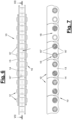
- the chain bolts (16) can be adjusted according to Figure 5 consist of an inner bolt (16') for connecting the outer chain plates (13) and a mounted sleeve (16") for connecting the inner chain plates (14).
- the rollers (17) are between the chain plate pairings and can be rotated freely on the Chain bolts (16), in particular on the sleeve (16"), are arranged.
- the push chain (10) is designed to be rigid in the back. It can transmit thrust forces when extended while maintaining its straight extension. In particular, the push chain (10) can extend out of the housing (2) in a vertical direction and lift a wing.
- the push chain (10) can be designed as a heavy-duty chain.
- the outer and inner chain plates (13, 14) have a flat or flat disc or plate shape.
- the inner and outer chain plates (13, 14) overlap each other in the longitudinal direction of the chain and are connected to one another by the chain bolts (16).
- the outer chain plates (13), which abut one another in the longitudinal direction of the chain, have a mutually adapted and preferably curved support contour (15). They support each other at the front.
- the chain bolts (16) are in accordance Figure 4 arranged off-center when viewed in the longitudinal direction of the chain. They are arranged closer to the front than to the back of the chain links (12) and their chain plates (13, 14). The free spaces (18) have accordingly Figure 5 a different depth.
- the chain plates (13, 14) are equipped with a wave shape or rounding on the front in the area of the chain bolts (16).
- the back side or top of the chain straps (13, 14) is straight.
- the contact points of the support contour (15) located on the end faces of the outer chain plates (13) are curved and are spaced apart from the row of chain bolts (16). This is favorable for high back rigidity of the push chain (10). Under shear loads, the chain links (12) can be supported against each other in a curve-tolerant manner via the end faces of the outer chain plates (13) and the support contour (15).
- the push chain (10) has an end piece (20).
- This can be provided with a limiting means (21) for the extension length of the push chain (10).
- the limiting means (21) can be formed, for example, by a pin projecting laterally beyond the end piece (20), in particular by an extended chain pin, which abuts a stop in front of or on the chain wheel.
- the chain station (11) has a chain guide (28), which according to Figure 4 and 5 engages in the push chain (10) on both sides and guides the rotatable rollers (17).
- the chain guide (28) engages on opposite sides of the push chain (10) and in the upper and lower free spaces (18) there. Through The chain guide (28) guides the push chain (10) in the chain station (11).
- the chain guide (28) has a spiral-like guide track (29) with several straight and curved guide sections (30, 31).
- the curved guide sections (31) form chain deflections between straight guide sections (30). In the preferred embodiment shown, there are three parallel straight guide sections (30) and two opposite curved guide sections (31) or chain deflections.
- the guide track (29) is designed as a slot-like space between the inner and outer guide elements of the chain guide (28).
- the guide track (29) is preferably designed to be continuous. It extends from an access (41) on one end face of the chain station (11) to an end (42), which is arranged, for example, on another opposite end face area.
- the slot-like guide track (29) is formed in the straight guide sections (30) between several straight and parallel guide elements (32, 33). In the curved guide sections (31), the guide track (29) is formed between inner and outer curved guide elements (37,38,39,40).
- the straight guide elements (32,33) are designed like a web. They are adapted to the respective inner space (18) of the push chain (10) and engage here. They protrude close to the rotatable rollers (17), with appropriate clearances being provided through the distances.
- the straight guide elements (32,33) have according to Figure 5 a different length.
- a curved inner guide element (37) is designed as a freely rotatable guide roller. This moves when the running push chain (10) is deflected.
- the associated curved outer guide element (39) is designed as a web-like round arch guide.
- the other curved inner guide element (38) is designed as a stationary and curved guide bar.
- the associated outer curved guide element (40) is in turn designed as a web-like round arch guide.
- the curved guide elements (37,38,39,40) are each attached to the front side of the housing or frame (22) of the chain station (11).
- the chain station (11) points according to Figures 3 to 5 a housing (22) which preferably encloses the received push chain (10) on all sides.
- a housing (22) which preferably encloses the received push chain (10) on all sides.
- a skeletal or frame-like frame with side openings can be present instead of the housing.
- the straight guide elements (32,33) are arranged in the housing or frame (22).
- the curved guide elements (37,38,39,40) are each attached to the front side of the housing or frame (22) of the chain station (11).
- the frame or housing (22) has a channel-shaped chain holder (23) with straight holder sections (24,25,26).
- the chain holder (23) has two or more, in particular three, straight and parallel holder sections (24, 25, 26).
- one or more curved receiving sections (27) can be present, which are in Figures 3 and 4 are indicated by dashed lines. Such curved receiving sections (27) can be arranged on one or both end faces of the chain station (11).
- the chain holder (23) can therefore have a spiral-like and circumferential channel shape.
- the curved receiving sections are missing, with the chain station (11) only having the straight receiving sections (24, 25, 26).
- the first receiving section (24) forms the access (41) with its front opening and is open on both front sides.
- the receiving section (25) above is open on one end face adjacent to the access (41).
- the opposite end forms the end (42) and is closed.
- the top and third receiving section (26) is open on both end faces.
- the push chain (10) entering at the access (41) reaches the uppermost third receiving section (26) via the first, lower receiving section (24) and the one adjoining chain deflection with the larger radius at the front and then via the other chain deflection with the narrower radius the middle receiving section (25). It is guided on the guide track (29) and the straight and curved guide sections (30,31).
- the guide elements (32,33,37,38,39,40) are arranged on the frame or housing (22) and protrude into the chain holder (23) on both sides or on opposite sides. Said straight guide elements can be formed on the frame or housing (22).
- Figure 5 shows such an embodiment with a housing (22) designed, for example, as an injection-molded part made of plastic or as an extruded part made of metal.
- the chain holder (23) covers the chain links (12) on their top and bottom. With the closed housing shape there is also a cover on the two side surfaces.
- the push chain (10) is pushed into the chain station (11) by the drive unit (3) and pulled out again.
- the rollers (17) are guided and supported on the rounded outer guide elements (39, 40) of the chain deflections or curved guide sections (31).
- the rollers (17) are guided and supported on the inner curved guide elements (37, 38). They roll along the said guide elements (37,38,396,40).
- the sleeves (16") mounted on the inner bolts (16') can be rotated or are rigidly arranged in receiving openings in the inner chain plates (14). They can, for example, be pressed into the receiving openings in the manner of a sleeve chain.
- the sleeves (16") roll or slide along said guide elements (37,38,396,40).
- the push chain (10) is otherwise designed in the same way as in the first exemplary embodiment, except for the rollers (17).
- the chain station (11) and the other components of the chain push drive ((1) are in the manner described above Figures 1 to 5 educated.
- the chain guide (28) which engages on both sides of the push chain (10) and its free spaces (18), contacts and guides the sleeves (16").
Landscapes
- Engineering & Computer Science (AREA)
- General Engineering & Computer Science (AREA)
- Mechanical Engineering (AREA)
- Devices For Conveying Motion By Means Of Endless Flexible Members (AREA)
Description
Die Erfindung betrifft einen Kettenschubantrieb und einen Kettenbahnhof mit den Merkmalen im Oberbegriff der selbstständigen Ansprüche.The invention relates to a chain push drive and a chain station with the features in the preamble of the independent claims.
Ein solcher Kettenbahnhof und Kettenschubantrieb sind aus der
Bei dem Kettenschubantrieb der
Die
Es ist Aufgabe der vorliegenden Erfindung, einen verbesserten Kettenschubantrieb aufzuzeigen.It is the object of the present invention to demonstrate an improved chain push drive.
Die Erfindung löst diese Aufgabe mit den Merkmalen in Anspruch 1.
Die beanspruchte Kettenschubantriebstechnik, d.h. der Kettenschubantrieb, der Kettenbahnhof und das Antriebsverfahren, haben verschiedene Vorteile.The invention solves this problem with the features in
The claimed chain pusher drive technology, ie the chain pusher drive, the chain station and the drive method, have various advantages.
Der Kettenbahnhof dient zur Aufnahme der eingefahrenen Schubkette des Kettenschubantriebs in einer Schleifen- oder Spiralform. Der Kettenbahnhof kann in einem Gehäuse des Kettenschubantriebs fest oder lose montiert sein. Durch Variation der Bahnhofslänge können unterschiedliche Kettenlängen aufgenommen werden.The chain station is used to accommodate the retracted push chain of the chain push drive in a loop or spiral shape. The chain station can be mounted firmly or loosely in a housing of the chain push drive. By varying the station length, different chain lengths can be accommodated.
Die beidseitig, d.h. an gegenüberliegenden Seiten, in die Schubkette eingreifende Kettenführung des Kettenbahnhofs kann die Schubkette an ihren drehbaren Rollen oder an den Kettenbolzen, insbesondere an aufgezogenen Hülsen, besonders gut und sicher sowie verkantungsfrei führen. Außerdem wird der Verschleiß am Kettenbahnhof und an der Schubkette gemindert. Der im Kettenbahnhof, insbesondere an Kettenumlenkungen, bestehende Widerstand beim Einfahren und Ausfahren der Schubkette wird gemindert. Die Antriebsleistung kann besser ausgenutzt und wirtschaftlicher eingesetzt werden.The chain guide of the chain station, which engages in the push chain on both sides, i.e. on opposite sides, can guide the push chain particularly well and safely and without jamming on its rotatable rollers or on the chain pins, in particular on mounted sleeves. In addition, wear on the chain station and the push chain is reduced. The resistance that exists in the chain station, especially at chain deflections, when the push chain is retracted and extended is reduced. The drive power can be better utilized and used more economically.
Die beanspruchte Kettenschub-Antriebstechnik ist in der Lage, auch großformatige und schwere Flügel zu bewegen. Dies ist selbst in schwierigen Lagen, z.B. bei relativ flach liegenden Dachfenstern von Glasfassaden möglich. Die Schubkette kann dabei auch mit einer überwiegend aufrechten oder senkrechten Richtungskomponente ausfahren und am Flügel angreifen.The claimed chain push drive technology is able to move even large and heavy sashes. This is possible even in difficult locations, e.g. with relatively flat roof windows on glass facades. The push chain can also extend with a predominantly upright or vertical directional component and attack the wing.
Die Kettenführung bildet eine spiralartige und kontinuierliche Führungsbahn für die drehbaren Rollen oder Kettenbolzen bzw. Hülsen. Die Schubkette kann dadurch im Kettenbahnhof zwängungsfrei und insbesondere auch mit weichen Rundungen in einer mehrgängigen Schleife oder einer Spiralform geführt werden. Die Führungsbahn weist hierfür mehrere gerade und rund gebogene Führungsabschnitte auf. Erfindungsgemäß ist die Führungsbahn als schlitzartiger Freiraum zwischen jeweiligen geraden und gebogenen Führungselementen ausgebildet. Die Rollen oder Kettenbolzen bzw. Hülsen können dadurch an der Ober- und Unterseite mit ausreichendem Spiel und großer Sicherheit geführt werden. Die beanspruchte Kettenführung ist auch günstig für das sichere Biegen der im Kettenbahnhof aufgenommenen Schubkette an den Kettenumlenkungen.The chain guide forms a spiral-like and continuous guideway for the rotating rollers or chain pins or sleeves. The push chain can therefore be guided in the chain station without any constraints and, in particular, with soft curves in a multi-start loop or a spiral shape. For this purpose, the guideway has several straight and curved guide sections. According to the invention, the guide track is designed as a slot-like free space between respective straight and curved guide elements. The rollers or chain pins or sleeves can therefore be guided on the top and bottom with sufficient play and great security. The stressed chain guide is also favorable for the safe bending of the push chain held in the chain station at the chain deflections.
Die geraden Führungselemente der Kettenführung sind stegartig ausgebildet und greifen in einen inneren Freiraum an der Ober- und Unterseite der Schubkette zwischen seitlich beabstandete Kettenlaschen ein. Sie können dabei an den Freiraum und dessen Abmessungen angepasst sein. Hierbei kann ein günstiges Führungsspiel eingestellt werden.The straight guide elements of the chain guide are designed like a web and engage in an inner space on the top and bottom of the push chain between laterally spaced chain plates. They can be adapted to the free space and its dimensions. A favorable leadership game can be set here.
Für eine sichere, weiche und widerstandsarme Kettenführung ist die Ausbildung eines gebogenen inneren Führungselements als drehbare Führungsrolle von Vorteil. Eine solche Führungsrolle distanziert zwar die anschließenden geraden Führungsabschnitte und die dortigen Kettenabschnitte. Der Gewinn an Führungsqualität kann dabei die leichte Zunahme an Bauhöhe des Kettenbahnhofs wettmachen. Eine solche Führungsrolle eignet sich besonders gut für eine starke Kettenumlenkung mit einem 180°-Winkel und einem kleinen Umlenkradius.For a safe, soft and low-resistance chain guide, the design of a curved inner guide element as a rotatable guide roller is advantageous. Such a guide roller distances the subsequent straight guide sections and the chain sections there. The gain in leadership quality can compensate for the slight increase in height of the chain station. Such a guide roller is particularly suitable for a strong chain deflection with a 180° angle and a small deflection radius.
Ein anderes gebogenes inneres Führungselement kann als stationäre und rund gebogene Führungsleiste ausgebildet sein. Dies ist vor allem für eine spiralartig gebogene Führungsbahn und einen größeren Höhenabstand der anschließenden geraden Führungsabschnitte von Vorteil. Eine solche Führungsleiste spart Platz in der Länge des Kettenbahnhofs.Another curved inner guide element can be designed as a stationary and curved guide bar. This is particularly advantageous for a spirally curved guideway and a larger height distance between the subsequent straight guide sections. Such a guide bar saves space along the length of the chain station.
Für beide Varianten eines inneren gebogenen Führungselements ist das jeweils zugeordnete gebogene äußere Führungselement als stegartige runde Bogenführung ausgebildet. Die gebogenen Führungselemente greifen ebenfalls führend in die besagten Freiräume der Schubkette ein.For both variants of an inner curved guide element, the respectively assigned curved outer guide element is designed as a web-like round arch guide. The curved guide elements also engage in the said free spaces of the push chain.
Der Kettenbahnhof kann ein offenes Gestell oder ein umfangseitig geschlossenes Gehäuse aufweisen. Das Gestell oder Gehäuse kann eine kanalförmige Kettenaufnahme mit geraden Aufnahmeabschnitten aufweisen. Zusätzlich können ein oder mehrere gebogene Aufnahmeabschnitte für eine durchgehende Kettenaufnahme vorhanden sein. Dies können z.B. durch Gehäuseansätze gebildet werden.The chain station can have an open frame or a housing that is closed on the circumference. The frame or housing can be channel-shaped Have chain holder with straight receiving sections. In addition, one or more curved receiving sections can be present for continuous chain receiving. These can be formed, for example, by housing attachments.
Die gebogenen Aufnahmeabschnitte können alternativ entfallen, wobei die Schubkette an den Kettenumlenkungen offen liegt und an den dortigen gebogenen Führungsabschnitten geführt ist. Das Gestell oder Gehäuse des Kettenbahnhofs kann unter Aussparung dieser ein oder mehren Kettenumlenkungen entsprechend verkürzt sein und nur die geraden Aufnahmeabschnitte aufweisen.Alternatively, the curved receiving sections can be omitted, with the push chain lying open on the chain deflections and being guided on the curved guide sections there. The frame or housing of the chain station can be shortened accordingly, leaving out these one or more chain deflections and only have the straight receiving sections.
Eine solche Gestaltung ist besonders aufwandsarm und kostengünstig. Sie ermöglicht auch eine leichte und kostengünstige Längenanpassung des Kettenbahnhofs an unterschiedliche Schubkettenlängen. Der beanspruchte Kettenschubantrieb ist variabel und lässt sich an verschiedene Einsatzzwecke, Einbaubedingungen und Lasten in der Art eines Baukastensystems aufwandsarm adaptieren.Such a design requires particularly little effort and is cost-effective. It also allows the length of the chain station to be easily and cost-effectively adjusted to suit different push chain lengths. The chain push drive used is variable and can be easily adapted to different purposes, installation conditions and loads in the manner of a modular system.
Die Kettenaufnahme kann zwei oder mehr gerade und parallele Aufnahmeabschnitte aufweisen. Vorzugsweise sind drei gerade Aufnahmeabschnitte vorhanden. Deren Zahl kann auch mehr als drei betragen. Durch diese Gestaltung kann eine große Kettenlänge schleifen- oder spiralförmig und mit gleichbleibender Biegerichtung in einem kompakten Kettenbahnhof untergebracht werden.The chain holder can have two or more straight and parallel holder sections. There are preferably three straight receiving sections. Their number can also be more than three. This design allows a large length of chain to be accommodated in a loop or spiral shape and with a constant bending direction in a compact chain station.
Die geraden und gebogenen Führungselemente können am Gestell oder Gehäuse angeordnet sein. Sie können beidseits bzw. aus entgegengesetzten Richtungen in die Kettenaufnahme und dort in die oberen und unteren Freiräume zwischen den seitlichen Laschen der Schubkette ragen. Die Kettenaufnahme kann andererseits die Kettenglieder an ihrer Ober- und Unterseite und ggfs. auch an den anderen Seiten bedecken und abschirmen.The straight and curved guide elements can be arranged on the frame or housing. They can protrude into the chain holder on both sides or from opposite directions and there into the upper and lower spaces between the side plates of the push chain. On the other hand, the chain holder can cover and shield the chain links on their top and bottom and if necessary also on the other sides.
Die Ausbildung der Schubkette mit beidseitigen, jeweils inneren und äußeren Kettenlaschen mit angepasster gebogener Stützkontur zwischen den benachbarten äußeren Kettenlaschen ist für die beanspruchte Ausbildung des Kettenbahnhofs und der Kettenführung von besonderem Vorteil. Die Schubkette kann dadurch ohne einen geschlossenen Rücken auskommen und hat trotzdem eine hohe Steifigkeit und Festigkeit. Sie kann als Schwerlastkette auch für schwergewichtige Flügel eingesetzt werden. Hierfür ist die widerstandsarme Kettenführung von besonderem Vorteil. Insbesondere kann die Schubkette an den Kettenumlenkungen bei Zug- und Schubbelastung gleichermaßen gut und sicher geführt werden.The design of the push chain with inner and outer chain plates on both sides with an adapted curved support contour between the adjacent outer chain plates is of particular advantage for the stressed design of the chain station and the chain guide. The push chain can therefore do without a closed back and still has a high level of rigidity and strength. It can also be used as a heavy-duty chain for heavy sashes. The low-resistance chain guide is particularly advantageous for this. In particular, the push chain can be guided equally well and safely on the chain deflections under tensile and shear loads.
Die Schubkette kann ein vorderes Mundstück und ein hinteres Endstück mit einem Begrenzungsmittel für ihre Ausfahrlänge aufweisen. Hierdurch wird ein versehentliches Austreiben der Schubkette durch ein außerhalb des Kettenbahnhofs angeordnetes Treibmittel des Antriebs, insbesondere ein Kettenrad, vermieden. Die Antriebseinheit des Kettenschubantriebs kann einen Motor, ein Getriebe und ein Kettenrad oder ein anderes Antriebsmittel aufweisen. Als Motor wird vorzugsweise ein bürstenloser Elektromotor eingesetzt. Dieser hat einen besonders hohen Wirkungsgrad, der sich optimal mit der Führungsqualität und der Widerstands- oder Reibungsarmut der Kettenführung ergänzt.The push chain may have a front mouthpiece and a rear end piece with a limiting means for its extension length. This prevents the push chain from being accidentally driven out by a propellant of the drive, in particular a chain wheel, arranged outside the chain station. The drive unit of the chain push drive can have a motor, a gearbox and a sprocket or another drive means. A brushless electric motor is preferably used as the motor. This has a particularly high level of efficiency, which complements the leadership quality and the low resistance or friction of the chain guide.
In den Unteransprüchen sind weitere vorteilhafte Ausgestaltungen der Erfindung angegeben.Further advantageous embodiments of the invention are specified in the subclaims.
Der beanspruchte Kettenschubantrieb und der beanspruchte Kettenbahnhof können die nachfolgenden vorteilhaften weiteren Ausgestaltungen einzeln oder in Kombination aufweisen.The claimed chain push drive and the claimed chain station can have the following advantageous further configurations individually or in combination.
Die Kettenaufnahme kann zwei oder mehr, insbesondere drei, gerade und parallele Aufnahmeabschnitte aufweisen.The chain holder can have two or more, in particular three, straight and parallel holder sections.
Die Kettenaufnahme kann die Kettenglieder an ihrer Ober- und Unterseite und ggf. an den Seiten bedecken.The chain holder can cover the chain links on their top and bottom and, if necessary, on the sides.
Die Schubkette kann ein vorderes Mundstück und ein hinteres Endstück mit einem Begrenzungsmittel für ihre Ausfahrlänge aufweisen.The push chain may have a front mouthpiece and a rear end piece with a limiting means for its extension length.
Die Erfindung ist in den Zeichnungen beispielhaft und schematisch dargestellt. Im Einzelnen zeigen:
- Figur 1:
- Eine teilweise aufgebrochene Draufsicht auf einen Kettenschubantrieb mit einer Schubkette und einem Kettenbahnhof,
- Figur 2:
- eine geschnittene und geklappte Stirnansicht des
Kettenschubantriebs von Figur 1 , - Figur 3:
- eine Seitenansicht des Kettenbahnhofs und der aufgenommenen Schubkette gemäß
Figur 2 in vergrößerter Darstellung, - Figur 4:
- eine geschnittene Seitenansicht des Kettenbahnhofs gemäß Schnittlinie IV-
IV von Figur 3 , - Figur 5:
- eine geschnittene Stirnansicht des Kettenbahnhofs gemäß Schnittlinie
V-V von Figur 4 , - Figur 6:
- eine Variante der Schubkette und
- Figur 7:
- einen Längsschnitt durch die Schubkette gemäß Schnittlinie VII -
VII von Figur 6 .
- Figure 1:
- A partially broken top view of a chain pusher drive with a pusher chain and a chain station,
- Figure 2:
- a cut and folded front view of the chain push drive from
Figure 1 , - Figure 3:
- a side view of the chain station and the included push chain
Figure 2 in an enlarged view, - Figure 4:
- a sectioned side view of the chain station according to section line IV-IV from
Figure 3 , - Figure 5:
- a sectioned front view of the chain station according to section line VV from
Figure 4 , - Figure 6:
- a variant of the push chain and
- Figure 7:
- a longitudinal section through the push chain according to section line VII - VII of
Figure 6 .
Die Erfindung betrifft einen Kettenschubantrieb (1), einen Kettenbahnhof (11) und ein Antriebsverfahren für bewegliche Flügel.The invention relates to a chain push drive (1), a chain station (11) and a drive method for movable wings.
Die beweglichen Flügel können Fensterflügel oder Klappen oder andere bewegliche, insbesondere schwenkbare, Gebäudeteile oder Öffnungsverschlüsse, z.B. auch Türen, sein. Die Flügel können auch als Hauben, Kuppeln, Dome oder dgl. ausgebildet sein. Die Flügel können Teile von Rauch-Wärme-Abzugsanlagen (RWA), automatisierten natürlichen Belüftungen oder dgl. sein und werden von dem Kettenschubantrieb (1) geöffnet und geschlossen.The movable sashes can be window sashes or flaps or other movable, in particular pivotable, building parts or opening closures, for example doors. The wings can also be designed as hoods, domes, domes or the like. The wings can be parts of smoke and heat extraction systems (RWA), automated natural ventilation or Like. And are opened and closed by the chain push drive (1).
Der Kettenschubantrieb (1) kann in beliebiger Lage an dem stationären Rahmen für den Flügel angeordnet sein. Eine bevorzugte Ausführungsform sieht vor, dass der Flügel Bestandteil eines schwach gegen die Horizontale geneigten Dachflächenfenster ist und von einem aufrecht im umgebenden Fensterrahmen eingebauten Kettenschubantrieb (1) betätigt wird. Der Kettenschubantrieb (1) kann alternativ auch am Flügel angebaut oder eingebaut sein.The chain push drive (1) can be arranged in any position on the stationary frame for the wing. A preferred embodiment provides that the sash is part of a roof window that is slightly inclined to the horizontal and is actuated by a chain push drive (1) installed upright in the surrounding window frame. Alternatively, the chain push drive (1) can also be attached or installed on the sash.
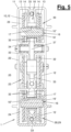
Der in
Der Kettenschubantrieb (1) besitzt ein Gehäuse (2), in dem eine Antriebseinheit (3) und ein Kettenbahnhof (11) zur platzsparenden Aufnahme der eingefahrenen Schubkette (10) in einer Spiralenform angeordnet sind. Das Gehäuse (2) kann z.B. als hohles Strangpressprofil ausgebildet sein, an dessen Mantel ein Kettenauslass (9) für die Schubkette (10) angeordnet ist und dessen Enden mit geeigneten Deckeln verschlossen werden.The chain pusher drive (1) has a housing (2) in which a drive unit (3) and a chain station (11) are arranged in a spiral shape to accommodate the retracted pusher chain (10) in a space-saving manner. The housing (2) can be designed, for example, as a hollow extruded profile, on the jacket of which a chain outlet (9) for the push chain (10) is arranged and the ends of which are closed with suitable covers.
An einer Gehäuseseite, insbesondere stirnseitig, kann ein Anschluss (8) für eine Versorgung des Kettenschubantriebs (1) angeordnet sein. Hier können z.B. elektrischer Strom und/oder Steuersignale übermittelt werden. Diese können z.B. von einer externen mobilen oder stationären sowie leitungsgebundenen oder drahtlosen Bedienungseinrichtung (nicht dargestellt), von einer übergeordneten Gebäude- oder Brandsteuerung, von benachbarten und im Verbund arbeitenden anderen Kettenschubantrieben (1) oder dgl. kommen.A connection (8) for supplying the chain push drive (1) can be arranged on one side of the housing, in particular on the front side. For example, electrical current and/or control signals can be transmitted here. These can come, for example, from an external mobile or stationary as well as wired or wireless operating device (not shown), from a higher-level building or fire control system, from neighboring and other chain push drives (1) working in a network, or the like.
Die Antriebseinheit (3) weist einen Motor (4), ein nachgeschaltetes Getriebe (5) und ein Antriebsmittel (6) für die Schubkette (10) auf, welches z.B. als Kettenrad ausgebildet ist. Der Motor (4) ist vorzugsweise als Elektromotor ausgebildet, der mit Netz-Wechselspannung oder mit einer niedrigeren Gleichspannung betrieben werden kann. Vorzugsweise handelt es sich um einen bürstenlosen Elektromotor. Die Antriebseinheit (3) kann eine Notentriegelung für den Blockierfall haben.The drive unit (3) has a motor (4), a downstream gearbox (5) and a drive means (6) for the push chain (10), which is designed, for example, as a chain wheel. The motor (4) is preferably designed as an electric motor that can be operated with AC mains voltage or with a lower DC voltage. It is preferably a brushless electric motor. The drive unit (3) can have an emergency release in the event of a blockage.
Die Schubkette (10) ist in
In der Ausführungsform von
Die Kettenglieder (12) weisen jeweils Kettenbolzen (16) auf, welche die Laschenpaarungen quer miteinander verbinden und eine Drehbeweglichkeit für die Kettenglieder (12) an Kettenumlenkungen bieten. Die Kettenbolzen (16) können gemäß
Die Schubkette (10) ist rückensteif ausgebildet. Sie kann beim Ausfahren Schubkräfte übertragen und behält dabei ihre gerade Erstreckung. Insbesondere kann die Schubkette (10) in vertikaler Richtung aus dem Gehäuse (2) ausfahren und einen Flügel anheben. Die Schubkette (10) kann als Schwerlastkette ausgebildet sein.The push chain (10) is designed to be rigid in the back. It can transmit thrust forces when extended while maintaining its straight extension. In particular, the push chain (10) can extend out of the housing (2) in a vertical direction and lift a wing. The push chain (10) can be designed as a heavy-duty chain.
Die äußeren und inneren Kettenlaschen (13,14) haben eine flache bzw. ebene Scheiben- oder Plattenform. Die inneren und äußeren Kettenlaschen (13,14) überlappen einander in Kettenlängsrichtung und sind dabei durch die Kettenbolzen (16) untereinander verbunden. Die in Kettenlängsrichtung aneinander stoßenden äußeren Kettenlaschen (13) weisen eine gegenseitig angepasste und bevorzugt gebogene Stützkontur (15) auf. Sie stützen sich stirnseitig aneinander ab.The outer and inner chain plates (13, 14) have a flat or flat disc or plate shape. The inner and outer chain plates (13, 14) overlap each other in the longitudinal direction of the chain and are connected to one another by the chain bolts (16). The outer chain plates (13), which abut one another in the longitudinal direction of the chain, have a mutually adapted and preferably curved support contour (15). They support each other at the front.
Die Kettenbolzen (16) sind gemäß
Die Kettenlaschen (13,14) sind an der Vorderseite im Bereich der Kettenbolzen (16) mit einer Wellenform oder Rundung ausgestattet. Die Rückenseite oder Oberseite der Kettenlaschen (13,14) ist gerade ausgebildet. Die an den Stirnseiten der äußeren Kettenlaschen (13) befindlichen Kontaktstellen der Stützkontur (15) sind gebogen und sind gegenüber der Reihe der Kettenbolzen (16) beabstandet. Dies ist für eine hohen Rückensteifigkeit der Schubkette (10) günstig. Bei Schubbelastung können sich die Kettenglieder (12) über die Stirnseiten der äußeren Kettenlaschen (13) und die Stützkontur (15) kurventolerant aneinander abstützen.The chain plates (13, 14) are equipped with a wave shape or rounding on the front in the area of the chain bolts (16). The back side or top of the chain straps (13, 14) is straight. The contact points of the support contour (15) located on the end faces of the outer chain plates (13) are curved and are spaced apart from the row of chain bolts (16). This is favorable for high back rigidity of the push chain (10). Under shear loads, the chain links (12) can be supported against each other in a curve-tolerant manner via the end faces of the outer chain plates (13) and the support contour (15).
Am hinteren Ende weist die Schubkette (10) ein Endstück (20) auf. Dieses kann mit einem Begrenzungsmittel (21) für die Ausfahrlänge der Schubkette (10) versehen sein. Das Begrenzungsmittel (21) kann z.B. von einem seitlich über das Endstück (20) vorstehenden Stift, insbesondere von einem verlängerten Kettenbolzen, gebildet werden, der vor oder am Kettenrad an einem Anschlag anläuft.At the rear end, the push chain (10) has an end piece (20). This can be provided with a limiting means (21) for the extension length of the push chain (10). The limiting means (21) can be formed, for example, by a pin projecting laterally beyond the end piece (20), in particular by an extended chain pin, which abuts a stop in front of or on the chain wheel.
Der Kettenbahnhof (11) weist eine Kettenführung (28) auf, die gemäß
Die Kettenführung (28) weist eine spiralartige Führungsbahn (29) mit mehreren geraden und rundgebogenen Führungsabschnitten (30,31) auf. Die gebogenen Führungsabschnitte (31) bilden Kettenumlenkungen zwischen geraden Führungsabschnitten (30). In der gezeigten und bevorzugten Ausführungsform sind drei parallele gerade Führungsabschnitte (30) und zwei einander gegenüberliegende gebogene Führungsabschnitte (31) bzw. Kettenumlenkungen vorhanden.The chain guide (28) has a spiral-like guide track (29) with several straight and curved guide sections (30, 31). The curved guide sections (31) form chain deflections between straight guide sections (30). In the preferred embodiment shown, there are three parallel straight guide sections (30) and two opposite curved guide sections (31) or chain deflections.
Die Führungsbahn (29) ist als schlitzartiger Freiraum zwischen jeweils inneren und äußeren Führungselementen der Kettenführung (28) ausgebildet. Die Führungsbahn (29) ist vorzugsweise kontinuierlich ausgebildet. Sie reicht von einem Zugang (41) an der einen Stirnseite des Kettenbahnhofs (11) bis zu einem Ende (42), das z.B. an anderen gegenüberliegenden Stirnseitenbereich angeordnet ist. Die schlitzartige Führungsbahn (29) ist in den geraden Führungsabschnitten (30) zwischen mehreren geraden und parallelen Führungselementen (32,33) ausgebildet. In den gebogenen Führungsabschnitten (31) ist die Führungsbahn (29) zwischen inneren und äußeren gebogenen Führungselementen (37,38,39,40) ausgebildet.The guide track (29) is designed as a slot-like space between the inner and outer guide elements of the chain guide (28). The guide track (29) is preferably designed to be continuous. It extends from an access (41) on one end face of the chain station (11) to an end (42), which is arranged, for example, on another opposite end face area. The slot-like guide track (29) is formed in the straight guide sections (30) between several straight and parallel guide elements (32, 33). In the curved guide sections (31), the guide track (29) is formed between inner and outer curved guide elements (37,38,39,40).
Die geraden Führungselemente (32,33) sind stegartig ausgebildet. Sie sind an den jeweiligen inneren Freiraum (18) der Schubkette (10) angepasst und greifen hier ein. Sie ragen dabei bis in die Nähe der drehbaren Rollen (17), wobei durch Abstände ein geeignetes Führungsspiel vorhanden ist. Die geraden Führungselemente (32,33) haben gemäß
Ein gebogenes inneres Führungselement (37) ist als frei drehbare Führungsrolle ausgebildet. Diese bewegt sich bei der Umlenkung der laufenden Schubkette (10) mit. Das zugeordnete gebogene äußere Führungselement (39) ist als stegartige runde Bogenführung ausgebildet.A curved inner guide element (37) is designed as a freely rotatable guide roller. This moves when the running push chain (10) is deflected. The associated curved outer guide element (39) is designed as a web-like round arch guide.
Das andere gebogene innere Führungselement (38) ist als stationäre und rundgebogene Führungsleiste ausgebildet. Das zugehörige äußere gebogene Führungselement (40) ist wiederum als stegartige runde Bogenführung ausgestaltet.The other curved inner guide element (38) is designed as a stationary and curved guide bar. The associated outer curved guide element (40) is in turn designed as a web-like round arch guide.
Die gebogenen Führungselemente (37,38,39,40) sind jeweils stirnseitig am Gehäuse oder Gestell (22) des Kettenbahnhofs (11) befestigt.The curved guide elements (37,38,39,40) are each attached to the front side of the housing or frame (22) of the chain station (11).
Der Kettenbahnhof (11) weist gemäß
Im Gehäuse oder Gestell (22) sind die geraden Führungselemente (32,33) angeordnet. Die gebogenen Führungselemente (37,38,39,40) sind jeweils stirnseitig am Gehäuse oder Gestell (22) des Kettenbahnhofs (11) befestigt.The straight guide elements (32,33) are arranged in the housing or frame (22). The curved guide elements (37,38,39,40) are each attached to the front side of the housing or frame (22) of the chain station (11).
Das Gestell oder Gehäuse (22) weist eine kanalförmige Kettenaufnahme (23) mit geraden Aufnahmeabschnitten (24,25,26) auf. Die Kettenaufnahme (23) hat zwei oder mehr, insbesondere drei, gerade und parallele Aufnahmeabschnitte (24,25,26). Außerdem können eine oder mehrere gebogene Aufnahmeabschnitte (27) vorhanden sein, die in
Der erste Aufnahmeabschnitt (24) bildet mit seiner Stirnöffnung den Zugang (41) und ist an beiden Stirnseiten offen. Der darüberliegende Aufnahmeabschnitt (25) ist an der einen und dem Zugang (41) benachbarten Stirnseite offen. Die gegenüberliegende Stirnseite bildet das Ende (42) und ist geschlossen. Der oberste und dritte Aufnahmeabschnitt (26) ist an beiden Stirnseiten offen.The first receiving section (24) forms the access (41) with its front opening and is open on both front sides. The receiving section (25) above is open on one end face adjacent to the access (41). The opposite end forms the end (42) and is closed. The top and third receiving section (26) is open on both end faces.
Die am Zugang (41) einlaufende Schubkette (10) gelangt über den ersten, unteren Aufnahmeabschnitt (24) und die eine stirnseitig anschließende Kettenumlenkung mit dem größeren Radius zu dem obersten dritten Aufnahmeabschnitt (26) und dann über die andere Kettenumlenkung mit dem engeren Radius in den mittleren Aufnahmeabschnitt (25). Sie wird dabei an der Führungsbahn (29) und den geraden und gebogenen Führungsabschnitten (30,31) geführt.The push chain (10) entering at the access (41) reaches the uppermost third receiving section (26) via the first, lower receiving section (24) and the one adjoining chain deflection with the larger radius at the front and then via the other chain deflection with the narrower radius the middle receiving section (25). It is guided on the guide track (29) and the straight and curved guide sections (30,31).
Die Führungselemente (32,33,37,38,39,40) sind am Gestell oder Gehäuse (22) angeordnet und ragen beidseits bzw. an gegenüberliegenden Seiten in die Kettenaufnahme (23). Die besagten geraden Führungselemente können am Gestell oder Gehäuse (22) angeformt sein.
Die Kettenaufnahme (23) bedeckt die Kettenglieder (12) an ihrer Oberseite und Unterseite. Bei der geschlossenen Gehäuseform ist auch eine Bedeckung an den beiden Seitenflächen vorhanden.The chain holder (23) covers the chain links (12) on their top and bottom. With the closed housing shape there is also a cover on the two side surfaces.
Die Schubkette (10) wird von der Antriebseinheit (3) in den Kettenbahnhof (11) eingeschoben und wieder herausgezogen. Beim Einschieben sind die Rollen (17) an den gerundeten äußeren Führungselementen (39,40) der Kettenumlenkungen bzw. gebogenen Führungsabschnitte (31) geführt und abgestützt. Beim Herausziehen der Schubkette (10) werden die Rollen (17) an den inneren gebogenen Führungselementen (37,38) geführt und abgestützt. Sie rollen dabei an den besagten Führungselementen (37,38,396,40) entlang.The push chain (10) is pushed into the chain station (11) by the drive unit (3) and pulled out again. When inserted, the rollers (17) are guided and supported on the rounded outer guide elements (39, 40) of the chain deflections or curved guide sections (31). When the push chain (10) is pulled out, the rollers (17) are guided and supported on the inner curved guide elements (37, 38). They roll along the said guide elements (37,38,396,40).
In der Variante der Schubkette (10) von
Die Schubkette (10) ist bis auf die Rollen (17) ansonsten in gleicher Weise wie im ersten Ausführungsbeispiel ausgebildet. Der Kettenbahnhof (11) und die anderen Komponenten des Kettenschubantriebs ((1) sind in der vorbeschriebenen Weise gemäß
Abwandlungen der gezeigten und beschriebenen Ausführungsformen sind im Rahmen der beigefügten Ansprüche in verschiedener Weise möglich.Modifications of the embodiments shown and described are possible in various ways within the scope of the appended claims.
- 11
- KettenschubantriebChain push drive
- 22
- GehäuseHousing
- 33
- Antriebdrive
- 44
- Motorengine
- 55
- Getriebetransmission
- 66
- KettenradSprocket
- 77
- Steuerungsteering
- 88th
- AnschlussConnection
- 99
- KettenauslassChain outlet
- 1010
- SchubkettePush chain
- 1111
- Kettenbahnhofchain station
- 1212
- Kettengliedchain link
- 1313
- Kettenlasche außenChain strap on the outside
- 1414
- Kettenlasche innenChain strap inside
- 1515
- StützkonturSupport contour
- 1616
- KettenbolzenChain pin
- 16'16'
- innerer Bolzeninner bolt
- 16"16"
- Hülsesleeve
- 1717
- Rollerole
- 1818
- Freiraumfree space
- 1919
- MundstückMouthpiece
- 2020
- EndstückEnd piece
- 2121
- BegrenzungsmittelLimiting means
- 2222
- Gehäuse, GestellHousing, frame
- 2323
- KettenaufnahmeChain holder
- 2424
- Aufnahmeabschnitt geradeRecording section straight
- 2525
- Aufnahmeabschnitt geradeRecording section straight
- 2626
- Aufnahmeabschnitt geradeRecording section straight
- 2727
- Aufnahmeabschnitt gebogenReceiving section curved
- 2828
- KettenführungChain guide
- 2929
- Führungsbahnguideway
- 3030
- Führungsabschnitt geradeGuide section straight
- 3131
- Führungsabschnitt gebogenGuide section curved
- 3232
- Führungselement, FührungsstegGuide element, guide bar
- 3333
- Führungselement, FührungsstegGuide element, guide bar
- 3434
- BodenFloor
- 3535
- DeckeCeiling
- 3636
- SeitenwandSide wall
- 3737
- Führungselement innen, UmlenkrolleGuide element inside, deflection roller
- 3838
- Führungselement innen, FührungsleisteGuide element inside, guide bar
- 3939
- Führungselement außen, Bogenführung außenGuide element on the outside, arch guide on the outside
- 4040
- Führungselement außen, Bogenführung außenGuide element on the outside, arch guide on the outside
- 4141
- ZugangAccess
- 4242
- EndeEnd
Claims (11)
- Chain station for a multi-link thrust chain (10) of a chain thrust drive (1) for movable casements, in particular window casements or flaps, wherein the chain station (11) has a chain guide (28) which is capable of engaging in the thrust chain (10) on both sides, wherein the chain guide (28) has a helical and continuous guide track (29) having a plurality of straight and round arcuate guide portions (30, 31), wherein the arcuate guide portions (31) form chain deflections between straight guide portions (30), and wherein the guide track (29) is configured as a slot-type void between straight guide elements (32, 33) and arcuate guide elements (37, 38, 39, 40) and the slot-type guide track (29) in the straight guide portions (30) is in each case configured between a plurality of straight and parallel guide elements (32, 33), and in the arcuate guide portions (31) is configured between inner and outer curved guide elements (37, 38, 39, 40), wherein an arcuate inner guide element (37, 38) is configured as a rotatable guide roller, and the arcuate outer guide elements (39, 40) are configured as web-type round arcuate guides, and wherein the straight guide elements (32, 33) of the chain guide (28) are configured in the manner of webs and can engage in an inner void (18) between laterally spaced-apart chain link plates (13, 14) on the upper and lower side of the thrust chain (10).
- Chain station according to Claim 1, characterized in that the chain guide (28) has three parallel straight guide portions (30) and two mutually opposite arcuate guide portions (31).
- Chain thrust drive for movable casements, in particular window casements or flaps, wherein the chain thrust drive (1) has a multi-link thrust chain (10) and a chain station (11) according to Claim 1 or 2, wherein the thrust chain (10) is configured as a roller chain having rotatable rollers (17) on the chain links (12), and has link pins (16) having fitted sleeves (16") on the chain links (12), wherein the chain guide (28) of the chain station (11) engages in the thrust chain (10) on both sides and guides the rollers (17) or sleeves (16").
- Chain thrust drive according to Claim 3, characterized in that the straight guide elements (32, 33) are configured in the manner of webs and adapted to an inner void (18) of the thrust chain (10) between laterally spaced-apart chain link plates (13, 14) .
- Chain thrust drive according to Claim 3 or 4, characterized in that the chain station (11) has a frame or housing (22) having a duct-shaped and optionally helical chain receptacle (23) having straight and optionally arcuate receptacle portions (24, 25, 26, 27).
- Chain thrust drive according to Claim 5, characterized in that the guide elements (32, 33, 37, 38, 39, 40) are disposed on the frame or housing (22), preferably moulded thereon, and protrude into the chain receptacle (23) on both sides.
- Chain thrust drive according to one of Claims 3 to 6, characterized in that the chain thrust drive (1) has a drive unit (3) having a motor (4), preferably a brushless electric motor, a gearbox (5), and a chain wheel (6).
- Chain thrust drive according to one of Claims 3 to 7, characterized in that the thrust chain (10) is configured with a rigid back.
- Chain thrust drive according to one of Claims 3 to 8, characterized in that the thrust chain (10) on both sides has inner and outer chain link plates (13, 14) which mutually overlap in the longitudinal direction of the chain and are connected by link pins (16).
- Chain thrust drive according to Claim 9, characterized in that the outer chain link plates (13) that abut one another in the longitudinal direction of the chain have a mutually adapted arcuate support contour (15).
- Chain thrust drive according to Claim 9 or 10, characterized in that the rollers (17) are disposed between the chain link plates (13, 14) on both sides and mounted so as to be rotatable on link pins (16).
Applications Claiming Priority (1)
| Application Number | Priority Date | Filing Date | Title |
|---|---|---|---|
| DE202017101221.2U DE202017101221U1 (en) | 2017-03-03 | 2017-03-03 | Chain thrust drive |
Publications (3)
| Publication Number | Publication Date |
|---|---|
| EP3369882A1 EP3369882A1 (en) | 2018-09-05 |
| EP3369882B1 EP3369882B1 (en) | 2021-01-27 |
| EP3369882B2 true EP3369882B2 (en) | 2024-03-13 |
Family
ID=62637052
Family Applications (1)
| Application Number | Title | Priority Date | Filing Date |
|---|---|---|---|
| EP18159719.6A Active EP3369882B2 (en) | 2017-03-03 | 2018-03-02 | Chain drive and chain station |
Country Status (3)
| Country | Link |
|---|---|
| EP (1) | EP3369882B2 (en) |
| DE (2) | DE202017101221U1 (en) |
| DK (1) | DK3369882T3 (en) |
Families Citing this family (1)
| Publication number | Priority date | Publication date | Assignee | Title |
|---|---|---|---|---|
| EP3872585A1 (en) * | 2020-02-26 | 2021-09-01 | Bulinfo Eood | Device for opening or closing of a window or door and a system and method for controlling and management of the air quality of indoor premises |
Family Cites Families (17)
| Publication number | Priority date | Publication date | Assignee | Title |
|---|---|---|---|---|
| US4014136A (en) | 1974-07-18 | 1977-03-29 | Teleflex Morse Limited | Means for the opening and closing of angularly movable panels |
| DE9321472U1 (en) | 1992-10-29 | 1998-10-08 | Hautau Gmbh W | Chain drive with internal drive motor |
| JP2969544B2 (en) | 1993-10-28 | 1999-11-02 | 東洋エクステリア株式会社 | Push-pull chain storage device for telescopic gates |
| AU717821B2 (en) | 1995-08-02 | 2000-04-06 | L.S.K. International Research Pty. Limited | Improved chain and casement window opening and closing mechanisms incorporating same |
| IT1291433B1 (en) | 1997-03-14 | 1999-01-11 | Topp Srl | ARTICULATED CHAIN ACTUATOR |
| CN101109253A (en) | 2003-02-25 | 2008-01-23 | Vkr控股公司 | Chain operator and its housing and chain box comprising connection device matched with a shell |
| EP1484465B1 (en) | 2003-06-06 | 2017-10-04 | WindowMaster A/S | Linear actuator with drive chains connectable by interlocking engagement members |
| CA2563978C (en) | 2004-05-12 | 2010-03-09 | Vkr Holding A/S | Push-pull chain and actuator |
| DE102010010719B4 (en) | 2010-03-09 | 2022-02-10 | Vkr Holding A/S | window operating device |
| US20110302843A1 (en) | 2010-06-11 | 2011-12-15 | Dallmann Brian D | Window drive with back-curving chain |
| CN103764934B (en) | 2011-03-16 | 2017-11-24 | 阿萨阿布洛伊澳大利亚有限公司 | Chain coiler for window OR gate |
| DE202011050625U1 (en) | 2011-07-04 | 2012-10-11 | D+H Mechatronic Ag | chain drive |
| DE202012001208U1 (en) | 2012-02-06 | 2012-03-08 | Vkr Holding A/S | Actuating device for a window or a door |
| DE202012003951U1 (en) | 2012-04-20 | 2012-05-11 | D+H Mechatronic Ag | chain drive |
| DE202012102423U1 (en) | 2012-07-02 | 2012-07-26 | D + H Mechatronic Aktiengesellschaft | chain drive |
| CN103899180B (en) | 2014-04-07 | 2016-10-05 | 江汇装饰用品(鹤山)有限公司 | A kind of window opener |
| DE202015100105U1 (en) | 2015-01-13 | 2016-04-11 | Aumüller Aumatic GmbH | Chain thrust drive |
-
2017
- 2017-03-03 DE DE202017101221.2U patent/DE202017101221U1/en active Active
-
2018
- 2018-03-02 DE DE102018104796.7A patent/DE102018104796A1/en active Pending
- 2018-03-02 EP EP18159719.6A patent/EP3369882B2/en active Active
- 2018-03-02 DK DK18159719.6T patent/DK3369882T3/en active
Also Published As
| Publication number | Publication date |
|---|---|
| EP3369882A1 (en) | 2018-09-05 |
| EP3369882B1 (en) | 2021-01-27 |
| DE102018104796A1 (en) | 2018-09-06 |
| DE202017101221U1 (en) | 2018-06-05 |
| DK3369882T3 (en) | 2021-04-19 |
Similar Documents
| Publication | Publication Date | Title |
|---|---|---|
| EP1250509B1 (en) | Sectional lifting door or folding door | |
| EP3245373B1 (en) | Thrust chain actuator | |
| EP3805513B1 (en) | Roller door | |
| EP0141805A2 (en) | Roller shutter | |
| EP2143862B1 (en) | Parallel exhibition window | |
| EP1923533A2 (en) | Roller gate | |
| EP2504505B1 (en) | Fitting for a slidable wing of windows or doors | |
| EP2317054A2 (en) | Sliding door | |
| EP3741948A1 (en) | Window or door | |
| EP3369882B2 (en) | Chain drive and chain station | |
| DE19819558A1 (en) | Automatic door installation with reduced structural height and simultaneously reduced horizontal structural depth | |
| EP0563517A1 (en) | Combined push and pull device | |
| DE102006005750B4 (en) | Roller shutter with a plurality of coupled slats | |
| EP1555379A1 (en) | Louvre with lamella | |
| EP0731247A2 (en) | Device for securing a shutter windable about a shaft | |
| EP1437475B1 (en) | Window or door with drive device | |
| EP1522666B1 (en) | Fitting for lifting and sliding doors or windows and carriage for such a fitting | |
| DE4031388A1 (en) | SIDE SECTIONAL OR ROUND DOOR, CEILING SECTIONAL | |
| DE202006008411U1 (en) | Sliding drive gear for casements is mounted in oblong housing on long side of fixed or casement frame so that sliding drive gear can also pivot about axis which is parallel to axis about which casement turns for wider opening angle | |
| EP2905409A1 (en) | Actuating device for a wing, as well as device for adjusting a plurality of wings | |
| DE10037329A1 (en) | Sectional vertical lift door or overhead door comprises a smaller door composed of several sections that tilt relative to one another and whose tilting axis runs coaxially to the tilting axis of the larger door sections | |
| EP2475833B1 (en) | Device for actuating an overhead door | |
| EP2878749B1 (en) | Sectional door with bolt assembly | |
| EP3868993B1 (en) | Sliding door, especially a cooling room sliding door | |
| EP4174268B1 (en) | Sliding door roller fitting and associated sliding door arrangement |
Legal Events
| Date | Code | Title | Description |
|---|---|---|---|
| PUAI | Public reference made under article 153(3) epc to a published international application that has entered the european phase |
Free format text: ORIGINAL CODE: 0009012 |
|
| STAA | Information on the status of an ep patent application or granted ep patent |
Free format text: STATUS: THE APPLICATION HAS BEEN PUBLISHED |
|
| AK | Designated contracting states |
Kind code of ref document: A1 Designated state(s): AL AT BE BG CH CY CZ DE DK EE ES FI FR GB GR HR HU IE IS IT LI LT LU LV MC MK MT NL NO PL PT RO RS SE SI SK SM TR |
|
| AX | Request for extension of the european patent |
Extension state: BA ME |
|
| STAA | Information on the status of an ep patent application or granted ep patent |
Free format text: STATUS: REQUEST FOR EXAMINATION WAS MADE |
|
| 17P | Request for examination filed |
Effective date: 20190228 |
|
| RBV | Designated contracting states (corrected) |
Designated state(s): AL AT BE BG CH CY CZ DE DK EE ES FI FR GB GR HR HU IE IS IT LI LT LU LV MC MK MT NL NO PL PT RO RS SE SI SK SM TR |
|
| GRAP | Despatch of communication of intention to grant a patent |
Free format text: ORIGINAL CODE: EPIDOSNIGR1 |
|
| STAA | Information on the status of an ep patent application or granted ep patent |
Free format text: STATUS: GRANT OF PATENT IS INTENDED |
|
| INTG | Intention to grant announced |
Effective date: 20200406 |
|
| GRAJ | Information related to disapproval of communication of intention to grant by the applicant or resumption of examination proceedings by the epo deleted |
Free format text: ORIGINAL CODE: EPIDOSDIGR1 |
|
| STAA | Information on the status of an ep patent application or granted ep patent |
Free format text: STATUS: REQUEST FOR EXAMINATION WAS MADE |
|
| INTC | Intention to grant announced (deleted) | ||
| GRAP | Despatch of communication of intention to grant a patent |
Free format text: ORIGINAL CODE: EPIDOSNIGR1 |
|
| STAA | Information on the status of an ep patent application or granted ep patent |
Free format text: STATUS: GRANT OF PATENT IS INTENDED |
|
| RIC1 | Information provided on ipc code assigned before grant |
Ipc: F16G 13/20 20060101ALI20200902BHEP Ipc: E05F 15/619 20150101ALI20200902BHEP Ipc: E05F 11/06 20060101AFI20200902BHEP |
|
| INTG | Intention to grant announced |
Effective date: 20201005 |
|
| GRAS | Grant fee paid |
Free format text: ORIGINAL CODE: EPIDOSNIGR3 |
|
| GRAA | (expected) grant |
Free format text: ORIGINAL CODE: 0009210 |
|
| STAA | Information on the status of an ep patent application or granted ep patent |
Free format text: STATUS: THE PATENT HAS BEEN GRANTED |
|
| AK | Designated contracting states |
Kind code of ref document: B1 Designated state(s): AL AT BE BG CH CY CZ DE DK EE ES FI FR GB GR HR HU IE IS IT LI LT LU LV MC MK MT NL NO PL PT RO RS SE SI SK SM TR |
|
| REG | Reference to a national code |
Ref country code: GB Ref legal event code: FG4D Free format text: NOT ENGLISH |
|
| REG | Reference to a national code |
Ref country code: CH Ref legal event code: EP |
|
| REG | Reference to a national code |
Ref country code: AT Ref legal event code: REF Ref document number: 1358493 Country of ref document: AT Kind code of ref document: T Effective date: 20210215 |
|
| REG | Reference to a national code |
Ref country code: IE Ref legal event code: FG4D Free format text: LANGUAGE OF EP DOCUMENT: GERMAN |
|
| REG | Reference to a national code |
Ref country code: DE Ref legal event code: R096 Ref document number: 502018003758 Country of ref document: DE |
|
| REG | Reference to a national code |
Ref country code: DK Ref legal event code: T3 Effective date: 20210413 |
|
| REG | Reference to a national code |
Ref country code: FI Ref legal event code: FGE |
|
| REG | Reference to a national code |
Ref country code: SE Ref legal event code: TRGR |
|
| REG | Reference to a national code |
Ref country code: NL Ref legal event code: MP Effective date: 20210127 |
|
| REG | Reference to a national code |
Ref country code: NO Ref legal event code: T2 Effective date: 20210127 |
|
| REG | Reference to a national code |
Ref country code: LT Ref legal event code: MG9D |
|
| PG25 | Lapsed in a contracting state [announced via postgrant information from national office to epo] |
Ref country code: GR Free format text: LAPSE BECAUSE OF FAILURE TO SUBMIT A TRANSLATION OF THE DESCRIPTION OR TO PAY THE FEE WITHIN THE PRESCRIBED TIME-LIMIT Effective date: 20210428 Ref country code: HR Free format text: LAPSE BECAUSE OF FAILURE TO SUBMIT A TRANSLATION OF THE DESCRIPTION OR TO PAY THE FEE WITHIN THE PRESCRIBED TIME-LIMIT Effective date: 20210127 Ref country code: PT Free format text: LAPSE BECAUSE OF FAILURE TO SUBMIT A TRANSLATION OF THE DESCRIPTION OR TO PAY THE FEE WITHIN THE PRESCRIBED TIME-LIMIT Effective date: 20210527 Ref country code: LT Free format text: LAPSE BECAUSE OF FAILURE TO SUBMIT A TRANSLATION OF THE DESCRIPTION OR TO PAY THE FEE WITHIN THE PRESCRIBED TIME-LIMIT Effective date: 20210127 Ref country code: BG Free format text: LAPSE BECAUSE OF FAILURE TO SUBMIT A TRANSLATION OF THE DESCRIPTION OR TO PAY THE FEE WITHIN THE PRESCRIBED TIME-LIMIT Effective date: 20210427 |
|
| PG25 | Lapsed in a contracting state [announced via postgrant information from national office to epo] |
Ref country code: PL Free format text: LAPSE BECAUSE OF FAILURE TO SUBMIT A TRANSLATION OF THE DESCRIPTION OR TO PAY THE FEE WITHIN THE PRESCRIBED TIME-LIMIT Effective date: 20210127 Ref country code: RS Free format text: LAPSE BECAUSE OF FAILURE TO SUBMIT A TRANSLATION OF THE DESCRIPTION OR TO PAY THE FEE WITHIN THE PRESCRIBED TIME-LIMIT Effective date: 20210127 Ref country code: LV Free format text: LAPSE BECAUSE OF FAILURE TO SUBMIT A TRANSLATION OF THE DESCRIPTION OR TO PAY THE FEE WITHIN THE PRESCRIBED TIME-LIMIT Effective date: 20210127 |
|
| PG25 | Lapsed in a contracting state [announced via postgrant information from national office to epo] |
Ref country code: IS Free format text: LAPSE BECAUSE OF FAILURE TO SUBMIT A TRANSLATION OF THE DESCRIPTION OR TO PAY THE FEE WITHIN THE PRESCRIBED TIME-LIMIT Effective date: 20210527 |
|
| REG | Reference to a national code |
Ref country code: DE Ref legal event code: R026 Ref document number: 502018003758 Country of ref document: DE |
|
| PLBI | Opposition filed |
Free format text: ORIGINAL CODE: 0009260 |
|
| PG25 | Lapsed in a contracting state [announced via postgrant information from national office to epo] |
Ref country code: SM Free format text: LAPSE BECAUSE OF FAILURE TO SUBMIT A TRANSLATION OF THE DESCRIPTION OR TO PAY THE FEE WITHIN THE PRESCRIBED TIME-LIMIT Effective date: 20210127 Ref country code: CZ Free format text: LAPSE BECAUSE OF FAILURE TO SUBMIT A TRANSLATION OF THE DESCRIPTION OR TO PAY THE FEE WITHIN THE PRESCRIBED TIME-LIMIT Effective date: 20210127 Ref country code: EE Free format text: LAPSE BECAUSE OF FAILURE TO SUBMIT A TRANSLATION OF THE DESCRIPTION OR TO PAY THE FEE WITHIN THE PRESCRIBED TIME-LIMIT Effective date: 20210127 Ref country code: MC Free format text: LAPSE BECAUSE OF FAILURE TO SUBMIT A TRANSLATION OF THE DESCRIPTION OR TO PAY THE FEE WITHIN THE PRESCRIBED TIME-LIMIT Effective date: 20210127 |
|
| PLBI | Opposition filed |
Free format text: ORIGINAL CODE: 0009260 |
|
| PLAX | Notice of opposition and request to file observation + time limit sent |
Free format text: ORIGINAL CODE: EPIDOSNOBS2 |
|
| REG | Reference to a national code |
Ref country code: FI Ref legal event code: MDE Opponent name: GEZE GMBH Ref country code: FI Ref legal event code: MDE Opponent name: VKR-HOLDING A/S |
|
| 26 | Opposition filed |
Opponent name: VKR-HOLDING A/S Effective date: 20211020 |
|
| PG25 | Lapsed in a contracting state [announced via postgrant information from national office to epo] |
Ref country code: RO Free format text: LAPSE BECAUSE OF FAILURE TO SUBMIT A TRANSLATION OF THE DESCRIPTION OR TO PAY THE FEE WITHIN THE PRESCRIBED TIME-LIMIT Effective date: 20210127 Ref country code: SK Free format text: LAPSE BECAUSE OF FAILURE TO SUBMIT A TRANSLATION OF THE DESCRIPTION OR TO PAY THE FEE WITHIN THE PRESCRIBED TIME-LIMIT Effective date: 20210127 |
|
| REG | Reference to a national code |
Ref country code: FI Ref legal event code: MDE Opponent name: GEZE GMBH Ref country code: FI Ref legal event code: MDE Opponent name: VKR-HOLDING A/S |
|
| 26 | Opposition filed |
Opponent name: GEZE GMBH Effective date: 20211026 |
|
| REG | Reference to a national code |
Ref country code: BE Ref legal event code: MM Effective date: 20210331 |
|
| PG25 | Lapsed in a contracting state [announced via postgrant information from national office to epo] |
Ref country code: ES Free format text: LAPSE BECAUSE OF FAILURE TO SUBMIT A TRANSLATION OF THE DESCRIPTION OR TO PAY THE FEE WITHIN THE PRESCRIBED TIME-LIMIT Effective date: 20210127 Ref country code: IE Free format text: LAPSE BECAUSE OF NON-PAYMENT OF DUE FEES Effective date: 20210302 Ref country code: FR Free format text: LAPSE BECAUSE OF NON-PAYMENT OF DUE FEES Effective date: 20210327 Ref country code: AL Free format text: LAPSE BECAUSE OF FAILURE TO SUBMIT A TRANSLATION OF THE DESCRIPTION OR TO PAY THE FEE WITHIN THE PRESCRIBED TIME-LIMIT Effective date: 20210127 Ref country code: LU Free format text: LAPSE BECAUSE OF NON-PAYMENT OF DUE FEES Effective date: 20210302 |
|
| PG25 | Lapsed in a contracting state [announced via postgrant information from national office to epo] |
Ref country code: SI Free format text: LAPSE BECAUSE OF FAILURE TO SUBMIT A TRANSLATION OF THE DESCRIPTION OR TO PAY THE FEE WITHIN THE PRESCRIBED TIME-LIMIT Effective date: 20210127 |
|
| PLBB | Reply of patent proprietor to notice(s) of opposition received |
Free format text: ORIGINAL CODE: EPIDOSNOBS3 |
|
| PG25 | Lapsed in a contracting state [announced via postgrant information from national office to epo] |
Ref country code: IT Free format text: LAPSE BECAUSE OF FAILURE TO SUBMIT A TRANSLATION OF THE DESCRIPTION OR TO PAY THE FEE WITHIN THE PRESCRIBED TIME-LIMIT Effective date: 20210127 |
|
| PG25 | Lapsed in a contracting state [announced via postgrant information from national office to epo] |
Ref country code: IS Free format text: LAPSE BECAUSE OF FAILURE TO SUBMIT A TRANSLATION OF THE DESCRIPTION OR TO PAY THE FEE WITHIN THE PRESCRIBED TIME-LIMIT Effective date: 20210527 |
|
| PG25 | Lapsed in a contracting state [announced via postgrant information from national office to epo] |
Ref country code: BE Free format text: LAPSE BECAUSE OF NON-PAYMENT OF DUE FEES Effective date: 20210331 |
|
| GBPC | Gb: european patent ceased through non-payment of renewal fee |
Effective date: 20220302 |
|
| PG25 | Lapsed in a contracting state [announced via postgrant information from national office to epo] |
Ref country code: GB Free format text: LAPSE BECAUSE OF NON-PAYMENT OF DUE FEES Effective date: 20220302 |
|
| PLAY | Examination report in opposition despatched + time limit |
Free format text: ORIGINAL CODE: EPIDOSNORE2 |
|
| PGFP | Annual fee paid to national office [announced via postgrant information from national office to epo] |
Ref country code: NO Payment date: 20230321 Year of fee payment: 6 Ref country code: DK Payment date: 20230323 Year of fee payment: 6 |
|
| PGFP | Annual fee paid to national office [announced via postgrant information from national office to epo] |
Ref country code: SE Payment date: 20230324 Year of fee payment: 6 |
|
| PLBC | Reply to examination report in opposition received |
Free format text: ORIGINAL CODE: EPIDOSNORE3 |
|
| PG25 | Lapsed in a contracting state [announced via postgrant information from national office to epo] |
Ref country code: NL Free format text: LAPSE BECAUSE OF NON-PAYMENT OF DUE FEES Effective date: 20210127 Ref country code: CY Free format text: LAPSE BECAUSE OF FAILURE TO SUBMIT A TRANSLATION OF THE DESCRIPTION OR TO PAY THE FEE WITHIN THE PRESCRIBED TIME-LIMIT Effective date: 20210127 |
|
| P01 | Opt-out of the competence of the unified patent court (upc) registered |
Effective date: 20230605 |
|
| PG25 | Lapsed in a contracting state [announced via postgrant information from national office to epo] |
Ref country code: HU Free format text: LAPSE BECAUSE OF FAILURE TO SUBMIT A TRANSLATION OF THE DESCRIPTION OR TO PAY THE FEE WITHIN THE PRESCRIBED TIME-LIMIT; INVALID AB INITIO Effective date: 20180302 |
|
| PGFP | Annual fee paid to national office [announced via postgrant information from national office to epo] |
Ref country code: CH Payment date: 20230402 Year of fee payment: 6 |
|
| APBM | Appeal reference recorded |
Free format text: ORIGINAL CODE: EPIDOSNREFNO |
|
| APBP | Date of receipt of notice of appeal recorded |
Free format text: ORIGINAL CODE: EPIDOSNNOA2O |
|
| APAH | Appeal reference modified |
Free format text: ORIGINAL CODE: EPIDOSCREFNO |
|
| APBU | Appeal procedure closed |
Free format text: ORIGINAL CODE: EPIDOSNNOA9O |
|
| PUAH | Patent maintained in amended form |
Free format text: ORIGINAL CODE: 0009272 |
|
| STAA | Information on the status of an ep patent application or granted ep patent |
Free format text: STATUS: PATENT MAINTAINED AS AMENDED |
|
| 27A | Patent maintained in amended form |
Effective date: 20240313 |
|
| AK | Designated contracting states |
Kind code of ref document: B2 Designated state(s): AL AT BE BG CH CY CZ DE DK EE ES FI FR GB GR HR HU IE IS IT LI LT LU LV MC MK MT NL NO PL PT RO RS SE SI SK SM TR |
|
| REG | Reference to a national code |
Ref country code: DE Ref legal event code: R102 Ref document number: 502018003758 Country of ref document: DE |
|
| PGFP | Annual fee paid to national office [announced via postgrant information from national office to epo] |
Ref country code: AT Payment date: 20240318 Year of fee payment: 7 |
|
| PG25 | Lapsed in a contracting state [announced via postgrant information from national office to epo] |
Ref country code: MK Free format text: LAPSE BECAUSE OF FAILURE TO SUBMIT A TRANSLATION OF THE DESCRIPTION OR TO PAY THE FEE WITHIN THE PRESCRIBED TIME-LIMIT Effective date: 20210127 |
|
| PGFP | Annual fee paid to national office [announced via postgrant information from national office to epo] |
Ref country code: FI Payment date: 20240319 Year of fee payment: 7 Ref country code: DE Payment date: 20240321 Year of fee payment: 7 |