EP2905409A1 - Actuating device for a wing, as well as device for adjusting a plurality of wings - Google Patents
Actuating device for a wing, as well as device for adjusting a plurality of wings Download PDFInfo
- Publication number
- EP2905409A1 EP2905409A1 EP14196892.5A EP14196892A EP2905409A1 EP 2905409 A1 EP2905409 A1 EP 2905409A1 EP 14196892 A EP14196892 A EP 14196892A EP 2905409 A1 EP2905409 A1 EP 2905409A1
- Authority
- EP
- European Patent Office
- Prior art keywords
- adjusting device
- drive
- housing
- drive shaft
- adjusting
- Prior art date
- Legal status (The legal status is an assumption and is not a legal conclusion. Google has not performed a legal analysis and makes no representation as to the accuracy of the status listed.)
- Withdrawn
Links
- 230000005540 biological transmission Effects 0.000 claims abstract description 21
- 238000003780 insertion Methods 0.000 claims abstract description 12
- 230000037431 insertion Effects 0.000 claims abstract description 11
- 230000008878 coupling Effects 0.000 claims description 6
- 238000010168 coupling process Methods 0.000 claims description 6
- 238000005859 coupling reaction Methods 0.000 claims description 6
- 230000008901 benefit Effects 0.000 description 3
- 238000009434 installation Methods 0.000 description 2
- 241001367035 Autographa nigrisigna Species 0.000 description 1
- 241000532368 Gallirallus philippensis Species 0.000 description 1
- 230000009471 action Effects 0.000 description 1
- 230000004323 axial length Effects 0.000 description 1
- 230000008859 change Effects 0.000 description 1
- 150000001875 compounds Chemical class 0.000 description 1
- 230000018109 developmental process Effects 0.000 description 1
- 238000006073 displacement reaction Methods 0.000 description 1
- 239000000428 dust Substances 0.000 description 1
- 230000000694 effects Effects 0.000 description 1
- 238000005516 engineering process Methods 0.000 description 1
- 230000009760 functional impairment Effects 0.000 description 1
- 230000003993 interaction Effects 0.000 description 1
- 238000005096 rolling process Methods 0.000 description 1
- 230000001360 synchronised effect Effects 0.000 description 1
Images


Classifications
-
- E—FIXED CONSTRUCTIONS
- E05—LOCKS; KEYS; WINDOW OR DOOR FITTINGS; SAFES
- E05F—DEVICES FOR MOVING WINGS INTO OPEN OR CLOSED POSITION; CHECKS FOR WINGS; WING FITTINGS NOT OTHERWISE PROVIDED FOR, CONCERNED WITH THE FUNCTIONING OF THE WING
- E05F11/00—Man-operated mechanisms for operating wings, including those which also operate the fastening
- E05F11/02—Man-operated mechanisms for operating wings, including those which also operate the fastening for wings in general, e.g. fanlights
- E05F11/04—Man-operated mechanisms for operating wings, including those which also operate the fastening for wings in general, e.g. fanlights with cords, chains or cables
- E05F11/06—Man-operated mechanisms for operating wings, including those which also operate the fastening for wings in general, e.g. fanlights with cords, chains or cables in guide-channels
-
- E—FIXED CONSTRUCTIONS
- E05—LOCKS; KEYS; WINDOW OR DOOR FITTINGS; SAFES
- E05F—DEVICES FOR MOVING WINGS INTO OPEN OR CLOSED POSITION; CHECKS FOR WINGS; WING FITTINGS NOT OTHERWISE PROVIDED FOR, CONCERNED WITH THE FUNCTIONING OF THE WING
- E05F15/00—Power-operated mechanisms for wings
- E05F15/60—Power-operated mechanisms for wings using electrical actuators
- E05F15/603—Power-operated mechanisms for wings using electrical actuators using rotary electromotors
- E05F15/611—Power-operated mechanisms for wings using electrical actuators using rotary electromotors for swinging wings
- E05F15/616—Power-operated mechanisms for wings using electrical actuators using rotary electromotors for swinging wings operated by push-pull mechanisms
- E05F15/619—Power-operated mechanisms for wings using electrical actuators using rotary electromotors for swinging wings operated by push-pull mechanisms using flexible or rigid rack-and-pinion arrangements
-
- E—FIXED CONSTRUCTIONS
- E05—LOCKS; KEYS; WINDOW OR DOOR FITTINGS; SAFES
- E05F—DEVICES FOR MOVING WINGS INTO OPEN OR CLOSED POSITION; CHECKS FOR WINGS; WING FITTINGS NOT OTHERWISE PROVIDED FOR, CONCERNED WITH THE FUNCTIONING OF THE WING
- E05F17/00—Special devices for shifting a plurality of wings operated simultaneously
-
- E—FIXED CONSTRUCTIONS
- E05—LOCKS; KEYS; WINDOW OR DOOR FITTINGS; SAFES
- E05Y—INDEXING SCHEME ASSOCIATED WITH SUBCLASSES E05D AND E05F, RELATING TO CONSTRUCTION ELEMENTS, ELECTRIC CONTROL, POWER SUPPLY, POWER SIGNAL OR TRANSMISSION, USER INTERFACES, MOUNTING OR COUPLING, DETAILS, ACCESSORIES, AUXILIARY OPERATIONS NOT OTHERWISE PROVIDED FOR, APPLICATION THEREOF
- E05Y2900/00—Application of doors, windows, wings or fittings thereof
- E05Y2900/10—Application of doors, windows, wings or fittings thereof for buildings or parts thereof
- E05Y2900/11—Application of doors, windows, wings or fittings thereof for buildings or parts thereof for industrial buildings
Definitions
- the invention relates to a control device for a wing according to the preamble of claim 1 and a device for adjusting a plurality of wings.
- Adjustments for wings such.
- flaps or door leaves are known in particular in the field of building technology in various designs.
- the opening and closing of wings can only serve an improved comfort with such an actuator.
- such actuators also provide the ability to provide a wall or roof opening at a location that is not or only with difficulty accessible to a person.
- a corresponding actuator may facilitate the adjustment of a single comparatively large wing or a plurality of wings.
- adjusting devices There are various types of adjusting devices in which a rigid rod is driven in the direction of its longitudinal axis to move at one end a window with which it is connected to a desired position and optionally also in that position. Furthermore It is known to transmit shear forces on casements with a chain. Many solutions are only limited suitable for a coordinated movement of several adjusting devices.
- the present invention has for its object to provide an adjusting device, which is improved in terms of accuracy and coordination of positioning movements.
- the invention is based on an adjusting device for a wing, which is movably mounted on a roof opening, for example, from.
- the adjusting device is equipped with a gear which is at least partially housed in a housing.
- the transmission comprises a push chain, which is designed for the transmission of restoring forces on the wing.
- a drive element of the transmission has an insertion opening or a through shaft for an outer drive shaft.
- the adjusting device according to the invention can advantageously provide more than one position for coupling to an external drive train.
- a drive torque from different sides with advantageously the same accuracy, e.g. a movement game, are initiated via the drive element.
- the housing preferably has openings on opposite sides through which the drive element, in particular the insertion opening for coupling an outer drive shaft, can be reached and, in particular, coupled to the outer drive shaft.
- the insertion opening is preferably formed continuously on the drive element such that an outer drive shaft in one and preferably can be passed in two opposite directions through the entire drive element.
- an insertion direction of the insertion opening is arranged parallel to a rotational axis of the drive element and in particular symmetrically to the axis of rotation on the drive element.
- the drive element is comparatively limited in its longitudinal extent along the axis of rotation. In this case, an axial length of the drive element and in particular of the through-hole on a recording of acting perpendicular to the axis of rotation bearing forces, z. B. for an outer drive shaft, adapted to avoid a concentrated introduction of such forces.
- the drive element of the transmission may extend from one side of the housing to an opposite side.
- An end portion of the drive element may be compared to an outer surface of the housing z. B. be offset inwardly, so that a compound of the continuous shaft with an external drive or output shaft can be advantageously protected by the housing.
- an end section of the drive element, in particular the continuous shaft can be brought out projecting on the housing. This results in the advantage that the drive element when connecting to an external drive or output shaft is relatively easily accessible.
- the adjusting device can be coupled in this way advantageously with little play to an external drive or output shaft to be coupled to a rotary drive and optionally with a further adjusting device.
- a preferred embodiment of the invention is that the drive element is arranged on a side region of the housing such that a straight and rigid drive shaft can be arranged on the side region over its entire extent in the longitudinal direction of the drive shaft.
- the housing preferably has a bearing section projecting on the side section, on which the drive element is movably mounted.
- the bearing portion may be formed on the housing as a projection, e.g. adapted to the drive element.
- the bearing section is preferably provided with bearing means, e.g. B. a rolling or a sliding bearing for storage of the drive element.
- the bearing portion can be advantageously tuned such that the bearing means against disturbing external influences such. Dust and e.g. Moisture protected.
- the bearing means can be adapted to a recording of load capacities of a coupled outer drive shaft.
- the bearing can be designed to float, in particular in the axial direction. This allows for a coupling to a comparatively long outer drive shaft z. B. compensate for their thermal change in length advantageous.
- for a drive element with an insertion opening of the projecting bearing portion may be formed, for example, annular, wherein a plane of the ring protrudes perpendicularly from the side portion.
- a preferred embodiment of the invention provides that the insertion opening of the drive element is designed for a positive and / or non-positive coupling with the drive shaft. As a result, a comparatively simple installation can be achieved. It is conceivable z. B. a form fit for circumferential forces and a traction for axial forces.
- the adjusting device comprises a housing which is designed to receive unloaded chain links of the push chain. This makes it possible, for example, in a greenhouse to avoid chain links in branches of tall plants can catch.
- a housing element which is provided for receiving push chain links may be separately exchangeable.
- the adjusting device can be comparatively easily adapted to different lengths of push chains.
- the housing preferably has an opening for extending and retracting the push chain, which is adapted to a cross section of the push chain.
- the cross section may e.g. be adapted so that body of a predetermined size, for. B. of leaves and z. B. of relatively small branches can not penetrate through the opening in the housing.
- one-sided hinged wings that perform a pivoting movement when opening and closing, cause the push chain at a retracting or retracting a pivoting movement, z. B. perpendicular to a rotational axis of an acting on the push chain drive wheel executes. Therefore, it is advantageous if the opening on the housing in the direction of pivotal movements, in particular with respect to a direction perpendicular thereto, is widened.
- rail or channel-shaped guide elements may be arranged, which preferably embrace the push chain sections. This makes it possible to avoid breakage, in particular due to articulated movements of chain links, which can reduce the transmission of drive and support forces to the push chain.
- at least one element of the guide means is arranged adjacent to the opening of the housing. Because the area between the opening and a force on the push chain from the transmission is relatively sensitive to a functional impairment and may be difficult to access under certain circumstances. Furthermore, it is conceivable that the element of the guide means projects through the opening.
- Guide element have a funnel-shaped collar, the Schubketten therefore when retracting the push chain in a z. B. guide channel, in which the push chain with a relatively small amount of movement -. B. of 10% or z. B. 5% or z. B. 2% or eg 1% of a maximum cross section of the thrust chain - is guided.
- the element of the guide means is preferably movably mounted and in particular adapted to a Mitschul during pivotal movements of the push chain. As a result, forces acting perpendicular to the thrust direction of the thrust chain can be reduced or avoided altogether in order to prevent the thrust chain from breaking out of a straight thrust line. B. between the opening and an attachment point on the wing to avoid.
- the guide element is configured as a pivoting element, for.
- Example in the form of a slider which is movable in the housing, so that an opening of the guide element, in which the push chain moves, can move in relation to the housing, so that predefined different chain tilt angle, especially in a fixed housing, can still be compensated.
- the housing has adjustment possibilities in order to be able to adjust its orientation in a predetermined range during a fixed installation. It is conceivable z.
- the assembly in different positions by a possibility of displacement of a mounting screw in a slot or a device with a threaded adjustment to position the fixed housing with respect to a pivot axis by adjusting the threaded device during assembly can.
- the adjusting device is designed for the transmission of tensile forces which are of the order of transferable shear forces.
- the adjusting device can preferably also advantageously be used for closing tensile-loaded window openings or window wings.
- a further preferred embodiment of the invention is that the adjusting device has attachment means with which the adjusting device can be attached to a traverse.
- the adjusting device may for example be equipped with an attachment angle. If the attachment means are adjustable or permit a plurality of, in particular continuously distributed attachment positions, attachment of the adjustment device can advantageously be achieved with little or no tension forces on the adjustment device and on an outer drive shaft attached thereto.
- a development of the inventive concept results in the form of a device for adjusting a plurality of wings or even a comparatively extended wings on a roof with a drive shaft and at least one adjusting device, but preferably two or more adjusting devices proposed according to one of claims 1 to 8.
- a continuous, in particular one-piece drive shaft which is thereby pushed through at each adjusting device by the push-through openings of the drive elements.
- the drive shaft may also be composed of a plurality of partial shafts, wherein two partial shafts may optionally be interconnected at a position between two actuating devices.
- the device according to the invention for adjusting a plurality of wings offers the advantage that the adjusting devices coupled with a single shaft move with comparatively accurate uniformity.
- the adjusting devices coupled with a single shaft move with comparatively accurate uniformity.
- at least two actuators which are mounted at a predetermined distance to adjust different wings, via a common drive shaft, which through the respective Drive elements are pushed through, coupled together.
- a movement offset between the two adjusting devices may be limited to the torsion of the common drive shaft over the predetermined distance.
- the drive shaft of a separately arranged drive in particular motor, z. B. geared motor or manual drive, is driven.
- FIG. 1 a first embodiment of an adjusting device 1 according to the invention is shown.
- the adjusting device has a housing 2, with two housing sections 2a and 2b.
- the housing section 2a is a Gearbox (not shown) housed, the output side can be ejected as a push chain with a push chain 4 through an opening 5 of the housing 2 and retracted.
- the individual chain links 6 are hinged together and shaped so that they together form a back-rigid chain, with the push forces or compressive forces via a link on a window sash (not shown) can be transmitted.
- the larger housing portion 2a is cuboidal and provided to accommodate those chain links 6 of the chain 4 in it, which are not used in a given position for the transmission of actuating or supporting forces.
- a drive element 3 is mounted, which is connected by gearing with the rest of the transmission of the adjusting device 1.
- the drive element 3 projects on the housing section 2b on two opposite sides 2d and 2e.
- the drive element 3 has an opening 8, through which a drive shaft can be inserted through the drive element 3 therethrough.
- the drive element 3 is designed such that it can be positively or non-positively connected to a drive shaft (not shown).
- FIG. 2 a second embodiment of an adjusting device according to the invention is shown, which differs from the first essentially in that the housing 2 has two openings 5 and the adjusting device 1 is adapted to two retracting chains 4 in particular at the same time or extend.
- FIG. 3 a device according to the invention for adjusting a plurality of wings 19 on a roof section 18 is shown.
- the device 20 comprises a plurality of adjusting devices 1, which are connected to each other by a common shaft 21 and are coupled to be movable.
- the adjusting devices 1 are attached to a roof beam 17 a, which is located at a lower edge of a roof opening, which can be closed by a plurality of top-hung window sash 19.
- the device 20 comprises a drive unit 22, the z. B. may include an electric motor.
- the drive unit 22 is provided to drive via the shaft 21, which is pushed through by the respective drive elements 3 of the adjusting device 1.
- all adjusting devices 1 are synchronized with each other via the common shaft 21 in order to simultaneously extend and retract the respective thrust chains 4 at the same speed.
- the drive unit 22 on a braking device (not shown), with which the shaft 21 can be held in an reached position.
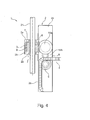
- FIG. 4 a further embodiment of an adjusting device 1 according to the invention is shown.
- the FIG. 4 illustrated actuator has some similarities with the in FIG. 1 shown embodiment and may be housed in a same housing 2.
- a drive shaft 21 is inserted through a drive element 3.
- the drive element 3 may, for. B. with a screw or z. B. worm gear (not shown) drive movements and drive torques transmitted to further transmission elements 10 a and 10 b of a transmission of the actuating device 1, which act on a drive wheel 9 of the transmission.
- the drive wheel 9 is connected to a push chain 4 in z. B. Reibkraft- or positive engagement and is provided for extending and retracting the push chain 4 through an opening 5.
- FIG. 5 a further embodiment of an adjusting device 1 according to the invention is shown, which has a relatively compact housing 2.
- a drive element 9 is mounted with an insertion opening 8.
- the drive element 9 is also intended to drive a push chain 4 directly and pushed out and retract at an opening 5 of the housing portion 2g.
- the drive element 9 may be for a non-positive or a interlocking interaction, in particular in a combination of both modes of action to be matched to the push chain 4.
- two guide elements 11 and 12 are mounted in the housing section 2g, with which the push chain 4 in the housing section 2g is guided fittingly on the drive element 9.
Landscapes
- Power-Operated Mechanisms For Wings (AREA)
Abstract
Es wird eine Stellvorrichtung (1) für einen Flügel (19) vorgeschlagen, der beweglich an einer z.B. Dachöffnung angebracht ist. Die Stellvorrichtung umfasst ein Getriebe (3, 9, 10a, 10b, 4), das zumindest teilweise in einem Gehäuse (2) untergebracht ist, wobei das Getriebe eine Schubkette (4) aufweist, die zur Übertragung von Stellkräften auf den Flügel (19) ausgebildet ist. Erfindungsgemäß besitzt ein Antriebselement (3) des Getriebes eine Durchstecköffnung (8) oder eine durchgehende Welle für eine äußere Antriebswelle (21).

Description
Die Erfindung betrifft eine Stellvorrichtung für einen Flügel nach dem Oberbegriff des Anspruchs 1 sowie eine Vorrichtung zur Einstellung von mehreren Flügeln.The invention relates to a control device for a wing according to the preamble of
Stellvorrichtungen für Flügel, wie z. B. Fensterflügel, Klappen oder Türflügel, sind insbesondere auf dem Gebiet der Gebäudetechnik in verschiedensten Ausführungen bekannt. Das Öffnen und Schließen von Flügeln kann mit einer derartigen Stellvorrichtung lediglich einem verbesserten Komfort dienen. Solche Stellvorrichtungen bieten jedoch auch die Möglichkeit, eine Wand- oder Dachöffnung an einer Stelle bereitzustellen, die für eine Person nicht oder nur mit Mühe erreichbar ist. Des Weiteren kann eine entsprechende Stellvorrichtung die Einstellung eines einzelnen vergleichsweise großen Flügels oder einer Vielzahl von Flügeln erleichtern.Adjustments for wings, such. As casements, flaps or door leaves are known in particular in the field of building technology in various designs. The opening and closing of wings can only serve an improved comfort with such an actuator. However, such actuators also provide the ability to provide a wall or roof opening at a location that is not or only with difficulty accessible to a person. Further, a corresponding actuator may facilitate the adjustment of a single comparatively large wing or a plurality of wings.
Es sind verschiedene Ausführungen von Stellvorrichtungen bekannt, bei denen eine starre Stange in Richtung deren Längsachse angetrieben wird, um mit einem Ende ein Fenster, mit dem es verbunden ist, in eine gewünschte Lage zu bewegen und gegebenenfalls in jener Lage auch zu halten. Des Weiteren ist es bekannt, Schubkräfte auf Fensterflügel mit einer Kette zu übertragen. Viele Lösungen sind dabei nur begrenzt für eine koordinierte Bewegung mehrerer Stellvorrichtungen geeignet.There are various types of adjusting devices are known in which a rigid rod is driven in the direction of its longitudinal axis to move at one end a window with which it is connected to a desired position and optionally also in that position. Furthermore It is known to transmit shear forces on casements with a chain. Many solutions are only limited suitable for a coordinated movement of several adjusting devices.
Der vorliegenden Erfindung liegt die Aufgabe zugrunde, eine Stellvorrichtung bereitzustellen, die hinsichtlich der Genauigkeit und Koordinierbarkeit von Stellbewegungen verbessert ist.The present invention has for its object to provide an adjusting device, which is improved in terms of accuracy and coordination of positioning movements.
Die Aufgabe wird mit einer Stellvorrichtung für einen Flügel mit den Merkmalen des Anspruchs 1 gelöst.The object is achieved with an adjusting device for a wing with the features of
Bevorzugte und vorteilhafte Ausführungen der Erfindung sind in den Unteransprüchen angegeben.Preferred and advantageous embodiments of the invention are specified in the subclaims.
Die Erfindung geht von einer Stellvorrichtung für einen Flügel, der beweglich an einer zum Beispiel Dachöffnung angebracht ist, aus. Die Stellvorrichtung ist mit einem Getriebe, das zumindest teilweise in einem Gehäuse untergebracht ist, ausgestattet. Dabei umfasst das Getriebe eine Schubkette, die zur Übertragung von Stellkräften auf den Flügel ausgebildet ist.The invention is based on an adjusting device for a wing, which is movably mounted on a roof opening, for example, from. The adjusting device is equipped with a gear which is at least partially housed in a housing. In this case, the transmission comprises a push chain, which is designed for the transmission of restoring forces on the wing.
Der Kern der Erfindung besteht darin, dass ein Antriebselement des Getriebes eine Durchstecköffnung oder eine durchgehende Welle für eine äußere Antriebswelle aufweist. Dadurch kann die erfindungsgemäße Stellvorrichtung vorteilhaft mehr als eine Position zur Ankopplung an einen äußeren Antriebsstrang bereitstellen. Dabei kann ein Antriebsmoment von verschiedenen Seiten her mit vorteilhaft gleicher Genauigkeit, z.B. eines Bewegungsspiels, über das Antriebselement eingeleitet werden.The essence of the invention is that a drive element of the transmission has an insertion opening or a through shaft for an outer drive shaft. As a result, the adjusting device according to the invention can advantageously provide more than one position for coupling to an external drive train. In this case, a drive torque from different sides with advantageously the same accuracy, e.g. a movement game, are initiated via the drive element.
Das Gehäuse weist vorzugsweise an einander gegenüberliegenden Seiten Öffnungen auf, durch die das Antriebselement, insbesondere die Durchstecköffnung zum Ankoppeln einer äußeren Antriebswelle erreichbar und insbesondere mit der äußeren Antriebswelle koppelbar ist. Die Durchstecköffnung ist am Antriebselement vorzugsweise derart durchgehend ausgebildet, dass sich eine äußere Antriebswelle in einer und vorzugsweise in zwei entgegengesetzten Richtungen durch das gesamte Antriebselement hindurchführen lässt. Vorzugsweise ist am Antriebselement eine Steckrichtung der Durchstecköffnung parallel zu einer Drehachse des Antriebselements und insbesondere symmetrisch zur Drehachse angeordnet. Dadurch ist das Antriebselement in seiner Längsausdehnung entlang der Drehachse vergleichsweise wenig beschränkt. Dabei kann eine axiale Länge des Antriebselements und insbesondere von dessen Durchstecköffnung auf eine Aufnahme von senkrecht zur Drehachse wirkenden Tragkräften, z. B. für eine äußere Antriebswelle, angepasst sein, um eine konzentrierte Einleitung solcher Kräfte zu vermeiden.The housing preferably has openings on opposite sides through which the drive element, in particular the insertion opening for coupling an outer drive shaft, can be reached and, in particular, coupled to the outer drive shaft. The insertion opening is preferably formed continuously on the drive element such that an outer drive shaft in one and preferably can be passed in two opposite directions through the entire drive element. Preferably, an insertion direction of the insertion opening is arranged parallel to a rotational axis of the drive element and in particular symmetrically to the axis of rotation on the drive element. As a result, the drive element is comparatively limited in its longitudinal extent along the axis of rotation. In this case, an axial length of the drive element and in particular of the through-hole on a recording of acting perpendicular to the axis of rotation bearing forces, z. B. for an outer drive shaft, adapted to avoid a concentrated introduction of such forces.
Bei einer Ausführung der Erfindung insbesondere mit der durchgehenden Welle kann das Antriebselement des Getriebes von einer Seite des Gehäuses bis zu einer gegenüberliegenden Seite reichen. Ein Endabschnitt des Antriebselements kann gegenüber einer Außenfläche des Gehäuses z. B. nach innen versetzt sein, damit eine Verbindung der durchgehenden Welle mit einer äußeren Antriebs- bzw. Abtriebswelle vorteilhaft durch das Gehäuse geschützt sein kann. Des Weiteren kann ein Endabschnitt des Antriebselements, insbesondere der durchgehenden Welle am Gehäuse überstehend herausgeführt sein. Dadurch ergibt sich der Vorteil, dass das Antriebselement beim Verbinden mit einer äußeren Antriebs- bzw. Abtriebswelle vergleichsweise leicht zugänglich ist. Die Stellvorrichtung lässt sich auf diese Weise vorteilhaft mit wenig Spiel an eine äußere Antriebs- bzw. Abtriebswelle ankoppeln, um mit einem Drehantrieb und gegebenenfalls mit einer weiteren Stellvorrichtung gekoppelt zu werden.In an embodiment of the invention, in particular with the continuous shaft, the drive element of the transmission may extend from one side of the housing to an opposite side. An end portion of the drive element may be compared to an outer surface of the housing z. B. be offset inwardly, so that a compound of the continuous shaft with an external drive or output shaft can be advantageously protected by the housing. Furthermore, an end section of the drive element, in particular the continuous shaft, can be brought out projecting on the housing. This results in the advantage that the drive element when connecting to an external drive or output shaft is relatively easily accessible. The adjusting device can be coupled in this way advantageously with little play to an external drive or output shaft to be coupled to a rotary drive and optionally with a further adjusting device.
Eine bevorzugte Ausführung der Erfindung besteht darin, dass das Antriebselement an einem Seitenbereich des Gehäuses derart angeordnet ist, dass sich eine gerade und starre Antriebswelle am Seitenbereich über dessen gesamte Ausdehnung in Längsrichtung der Antriebswelle anordnen lässt. Dies bietet den Vorteil, dass ein Durchstecken einer durchgehenden Welle durch die Durchstecköffnung derart erfolgen kann, dass die Welle ungehindert bis zu einer nächsten Stellvorrichtung weiter geführt werden kann.A preferred embodiment of the invention is that the drive element is arranged on a side region of the housing such that a straight and rigid drive shaft can be arranged on the side region over its entire extent in the longitudinal direction of the drive shaft. This offers the advantage that a passage through a through shaft through the insertion opening can be made such that the shaft unhindered until a next adjusting device can be continued.
Vorzugsweise weist das Gehäuse einen am Seitenabschnitt vorstehenden Lagerabschnitt auf, an dem das Antriebselement beweglich gelagert ist. Dabei kann der Lagerabschnitt am Gehäuse als Vorsprung ausgebildet sein, der z.B. an das Antriebselement angepasst ist. Der Lagerabschnitt ist vorzugsweise mit Lagermitteln, z. B. einem Wälz- oder einem Gleitlager für eine Lagerung des Antriebselements ausgebildet. Der Lagerabschnitt lässt sich vorteilhaft derart abstimmen, dass die Lagermittel vor störenden äußeren Einflüssen wie z. B. Staub und z.B. Feuchtigkeitgeschützt ist. Die Lagermittel können auf eine Aufnahme von Tragkräften einer angekoppelten äußeren Antriebswelle abgestimmt sein. Ferner kann die Lagerung insbesondere in axialer Richtung schwimmend ausgeführt sein. Dadurch lässt sich bei einer Ankopplung an eine vergleichsweise lange äußere Antriebswelle z. B. deren thermische Längenänderung vorteilhaft kompensieren. Insbesondere für ein Antriebselement mit einer Durchstecköffnung kann der vorstehende Lagerabschnitt beispielsweise ringförmig ausgebildet sein, wobei eine Ebene des Rings senkrecht vom Seitenabschnitt absteht.The housing preferably has a bearing section projecting on the side section, on which the drive element is movably mounted. In this case, the bearing portion may be formed on the housing as a projection, e.g. adapted to the drive element. The bearing section is preferably provided with bearing means, e.g. B. a rolling or a sliding bearing for storage of the drive element. The bearing portion can be advantageously tuned such that the bearing means against disturbing external influences such. Dust and e.g. Moisture protected. The bearing means can be adapted to a recording of load capacities of a coupled outer drive shaft. Furthermore, the bearing can be designed to float, in particular in the axial direction. This allows for a coupling to a comparatively long outer drive shaft z. B. compensate for their thermal change in length advantageous. In particular, for a drive element with an insertion opening of the projecting bearing portion may be formed, for example, annular, wherein a plane of the ring protrudes perpendicularly from the side portion.
Hierdurch ist eine vergleichsweise zuverlässige Ankopplung zwischen einer äußeren Antriebswelle und der Stellvorrichtung erreichbar.As a result, a comparatively reliable coupling between an outer drive shaft and the adjusting device can be achieved.
Eine bevorzugte Ausführung der Erfindung sieht vor, dass die Durchstecköffnung des Antriebselements für eine formschlüssige und/oder kraftschlüssige Kopplung mit der Antriebswelle ausgebildet ist. Dadurch ist eine vergleichsweise einfache Montage erreichbar. Denkbar ist z. B. ein Formschluss für umfängliche Kräfte und ein Kraftschluss für axiale Kräfte.A preferred embodiment of the invention provides that the insertion opening of the drive element is designed for a positive and / or non-positive coupling with the drive shaft. As a result, a comparatively simple installation can be achieved. It is conceivable z. B. a form fit for circumferential forces and a traction for axial forces.
Des Weiteren ist es bevorzugt, dass die Stellvorrichtung ein Gehäuse umfasst, das zur Aufnahme von unbelasteten Kettengliedern der Schubkette ausgebildet ist. Dadurch lässt sich beispielsweise in einem Gewächshaus vermeiden, dass sich Kettenglieder in Zweigen von hoch wachsenden Pflanzen verfangen können.Furthermore, it is preferred that the adjusting device comprises a housing which is designed to receive unloaded chain links of the push chain. This makes it possible, for example, in a greenhouse to avoid chain links in branches of tall plants can catch.
Dabei kann ein Gehäuseelement, das zur Aufnahme von Schubkettengliedern vorgesehen ist, separat austauschbar sein. Dadurch lässt sich die Stellvorrichtung vergleichsweise einfach an unterschiedlich lange Schubketten anpassen.In this case, a housing element which is provided for receiving push chain links may be separately exchangeable. As a result, the adjusting device can be comparatively easily adapted to different lengths of push chains.
Das Gehäuse weist vorzugsweise eine Öffnung zum Aus- und Einfahren der Schubkette auf, die an einen Querschnitt der Schubkette angepasst ist. Dabei kann der Querschnitt z.B. derart angepasst sein, dass Körper einer vorgegebenen Größe, z. B. von Laubblättern und z. B. von vergleichsweise kleinen Zweigen nicht durch die Öffnung in das Gehäuse eindringen können.The housing preferably has an opening for extending and retracting the push chain, which is adapted to a cross section of the push chain. The cross section may e.g. be adapted so that body of a predetermined size, for. B. of leaves and z. B. of relatively small branches can not penetrate through the opening in the housing.
Insbesondere einseitig angeschlagene Flügel, die beim Öffnen und Schließen eine Schwenkbewegung ausführen, bewirken, dass auch die Schubkette bei einem Ausfahren oder Einfahren eine Schwenkbewegung, z. B. senkrecht zu einer Drehachse eines auf die Schubkette wirkenden Treibrades, ausführt. Daher ist es vorteilhaft, wenn die Öffnung am Gehäuse in Richtung von Schwenkbewegungen, insbesondere gegenüber einer dazu senkrechten Richtung, aufgeweitet ist.In particular, one-sided hinged wings that perform a pivoting movement when opening and closing, cause the push chain at a retracting or retracting a pivoting movement, z. B. perpendicular to a rotational axis of an acting on the push chain drive wheel executes. Therefore, it is advantageous if the opening on the housing in the direction of pivotal movements, in particular with respect to a direction perpendicular thereto, is widened.
Um eine zuverlässige Kraftübertragung auf die Schubkette zu gewährleisten, können in der Stellvorrichtung, insbesondere innerhalb des Gehäuses z. B. schienen- oder kanalförmige Führungselemente angeordnet sein, die die Schubkette vorzugsweise abschnittsweise umgreifen. Dadurch lässt sich ein Ausbrechen, insbesondere durch Knickbewegungen von Kettengliedern vermeiden, dass eine Übertragung von Antriebs- und Stützkräften auf die Schubkette verringern kann. Dabei ist vorzugsweise zumindest ein Element der Führungsmittel an der Öffnung des Gehäuses angrenzend angeordnet. Denn der Bereich zwischen der Öffnung und einer Krafteinleitung auf die Schubkette vom Getriebe ist vergleichsweise empfindlich für eine Funktionsbeeinträchtigung und kann unter Umständen schwer zugänglich sein. Ferner ist es denkbar, dass das Element der Führungsmittel durch die Öffnung hindurchragt. Dabei kann das Führungselement einen trichterförmigen Kragen aufweisen, der die Schubketteinsbesondere beim Einfahren der Schubkette in einen z. B. Führungskanal leitet, in dem die Schubkette mit einem vergleichsweise kleinen Bewegungsspiel - z. B. von 10% oder z. B. 5% oder z. B. 2% oder z.B. von 1% eines maximalen Querschnitts der Schubkette - geführt ist. Das Element der Führungsmittel ist vorzugsweise beweglich gelagert und insbesondere auf eine Mitbewegung bei Schwenkbewegungen der Schubkette abgestimmt. Dadurch lassen sich senkrecht zur Schubrichtung der Schubkette wirkende Kräfte verringern oder ganz vermeiden, um ein Ausbrechen der Schubkette aus einer geraden Schublinie z. B. zwischen der Öffnung und einer Anbringstelle am Flügel zu vermeiden.In order to ensure a reliable power transmission to the push chain, in the adjusting device, in particular within the housing z. B. rail or channel-shaped guide elements may be arranged, which preferably embrace the push chain sections. This makes it possible to avoid breakage, in particular due to articulated movements of chain links, which can reduce the transmission of drive and support forces to the push chain. In this case, preferably at least one element of the guide means is arranged adjacent to the opening of the housing. Because the area between the opening and a force on the push chain from the transmission is relatively sensitive to a functional impairment and may be difficult to access under certain circumstances. Furthermore, it is conceivable that the element of the guide means projects through the opening. It can do that Guide element have a funnel-shaped collar, the Schubketteninsbesondere when retracting the push chain in a z. B. guide channel, in which the push chain with a relatively small amount of movement -. B. of 10% or z. B. 5% or z. B. 2% or eg 1% of a maximum cross section of the thrust chain - is guided. The element of the guide means is preferably movably mounted and in particular adapted to a Mitbewegung during pivotal movements of the push chain. As a result, forces acting perpendicular to the thrust direction of the thrust chain can be reduced or avoided altogether in order to prevent the thrust chain from breaking out of a straight thrust line. B. between the opening and an attachment point on the wing to avoid.
In einer insbesondere vorteilhaften Ausgestaltung der Erfindung ist das Führungselement als Schwenkelement ausgestaltet, z. B. in Form eines Gleitstücks, das im Gehäuse bewegbar ist, sodass sich eine Öffnung des Führungselements, in welcher sich die Schubkette bewegt, in Bezug auf das Gehäuse bewegen kann, sodass vordefinierte unterschiedliche Kettenneigungswinkel, insbesondere bei festgelegtem Gehäuse, dennoch ausgeglichen werden können.In a particularly advantageous embodiment of the invention, the guide element is configured as a pivoting element, for. Example, in the form of a slider which is movable in the housing, so that an opening of the guide element, in which the push chain moves, can move in relation to the housing, so that predefined different chain tilt angle, especially in a fixed housing, can still be compensated.
Des Weiteren ist es vorteilhaft, wenn das Gehäuse Justiermöglichkeiten aufweist, um es bei einer fixen Montage in seiner Ausrichtung in einem vorgegebenen Bereich einstellen zu können. Denkbar ist z. B. die Montage in unterschiedlichen Positionen durch eine Verschiebemöglichkeit einer Montageschraube in einem Langloch oder eine Einrichtung mit einer Gewindeverstellung, um das fix montierte Gehäuse in Bezug auf eine Schwenkachse durch Verstellen der Gewindeeinrichtung bei der Montage positionieren zu können.Furthermore, it is advantageous if the housing has adjustment possibilities in order to be able to adjust its orientation in a predetermined range during a fixed installation. It is conceivable z. Example, the assembly in different positions by a possibility of displacement of a mounting screw in a slot or a device with a threaded adjustment to position the fixed housing with respect to a pivot axis by adjusting the threaded device during assembly can.
Vorzugsweise ist die Stellvorrichtung zur Übertragung von Zugkräften ausgelegt, die in der Größenordnung übertragbarer Schubkräfte liegen. Hierdurch lässt sich die Stellvorrichtung vorzugsweise vorteilhaft auch zum Zuziehen von zugbelasteten Fensteröffnungen bzw. Fensterflügeln einsetzen.Preferably, the adjusting device is designed for the transmission of tensile forces which are of the order of transferable shear forces. As a result, the adjusting device can preferably also advantageously be used for closing tensile-loaded window openings or window wings.
Eine weitere bevorzugte Ausführung der Erfindung besteht darin, dass die Stellvorrichtung Anbringmittel aufweist, mit denen die Stellvorrichtung an einer Traverse anbringbar ist. Hierfür kann die Stellvorrichtung beispielsweise mit einem Anbringwinkel ausgestattet sein. Wenn die Anbringmittel einstellbar sind bzw. mehrere, insbesondere kontinuierlich verteilte Anbringpositionen erlauben, lässt sich eine Anbringung der Stellvorrichtung vorteilhaft mit geringen oder ohne Spannungskräften an der Stellvorrichtung und an einer daran angebrachten äußeren Antriebswelle erreichen.A further preferred embodiment of the invention is that the adjusting device has attachment means with which the adjusting device can be attached to a traverse. For this purpose, the adjusting device may for example be equipped with an attachment angle. If the attachment means are adjustable or permit a plurality of, in particular continuously distributed attachment positions, attachment of the adjustment device can advantageously be achieved with little or no tension forces on the adjustment device and on an outer drive shaft attached thereto.
Eine Weiterbildung der Erfindungsgedankens ergibt sich in Form einer Vorrichtung zur Einstellung von mehreren Flügeln bzw. auch einem vergleichsweise lang ausgedehnten Flügel an einem Dach mit einer Antriebswelle und mit mindestens einer Stellvorrichtung, vorzugsweise jedoch zwei oder mehr Stellvorrichtungen nach einem der Ansprüche 1 bis 8 vorgeschlagen. Dabei werden vorzugsweise zwei oder drei oder mehr erfindungsgemäße Stellvorrichtungen gemeinsam mit einer durchgehenden, insbesondere einstückigen Antriebswelle angetrieben, die dabei an jeder Stellvorrichtung durch die Durchstecköffnungen der Antriebselemente durchgesteckt ist. Anstelle einer einstückigen Antriebswelle kann die Antriebswelle auch aus mehreren Teilwellen zusammengesetzt sein, wobei zwei Teilwellen gegebenenfalls an einer Position zwischen zwei Stellvorrichtungen miteinander verbunden sein können. Dabei bietet die erfindungsgemäße Vorrichtung zur Einstellung mehrerer Flügel den Vorteil, dass sich die mit einer einzigen Welle gekoppelten Stellvorrichtungen mit einer vergleichesweise genauen Gleichförmigkeit bewegen. Auf diese Weise lassen sich entweder mehrere, insbesondere nebeneinander angeordnete Flügel an einem Dach oder ein durchgehender, insbesondere oben oder unten angeschlagener großer Flügel durch mehrere Stellvorrichtungen derart antreiben, dass zwischen den Stellvorrichtungen ein vergleichsweise geringer Bewegungsversatz auftritt. Vorzugsweise sind mindestens zwei Stellvorrichtungen, die in einem vorgegebenen Abstand zur Einstellung verschiedener Flügel montiert sind, über eine gemeinsame Antriebswelle, die durch die jeweiligen Antriebselemente durchgesteckt sind, miteinander gekoppelt. Dadurch kann ein Bewegungsversatz zwischen den beiden Stellvorrichtungen auf die Torsion der gemeinsamen Antriebswelle über den vorgegebenen Abstand begrenzt sein.A development of the inventive concept results in the form of a device for adjusting a plurality of wings or even a comparatively extended wings on a roof with a drive shaft and at least one adjusting device, but preferably two or more adjusting devices proposed according to one of
Insbesondere ist es bevorzugt, dass die Antriebswelle von einem separat angeordneten Antrieb, insbesondere Motor, z. B. Getriebemotor oder Handantrieb, angetrieben ist.In particular, it is preferred that the drive shaft of a separately arranged drive, in particular motor, z. B. geared motor or manual drive, is driven.
Nachfolgend wird die Erfindung anhand mehrerer Ausführungsbeispiele erläutert und mit Hilfe der Zeichnungen beschrieben. Merkmale mit ähnlicher Wirkung bzw. Funktion, die in mehreren Figuren gezeigt sind, sind in allen Figuren mit gleichen Bezugszeichen bezeichnet.The invention will be explained with reference to several embodiments and described with the aid of the drawings. Features having a similar effect or function, which are shown in several figures, are denoted by the same reference numerals in all figures.
Es zeigen
Figur 1- eine erste ausführungsgemäße Stellvorrichtung in schematischer, perspektivischer Ansicht,
Figur 2- ein zweites Ausführungsbeispiel einer erfindungsgemäßen Stellvorrichtung in schematischer, perspektivischer Ansicht,
Figur 3- eine schematische, perspektivische Ansicht einer erfindungsgemäßen Stellanlage mit mehreren Stellvorrichtungen,
Figur 4- eine Schnittansicht von oben einer Stellvorrichtung,
Figur 5- eine schematische Schnittansicht einer weiteren Stellvorrichtung in einer Schnittebene senkrecht zu einer Antriebswelle.
- FIG. 1
- a first embodiment actuating device in a schematic, perspective view,
- FIG. 2
- A second embodiment of an adjusting device according to the invention in a schematic, perspective view,
- FIG. 3
- a schematic, perspective view of a control system according to the invention with several adjusting devices,
- FIG. 4
- a sectional view from above of an adjusting device,
- FIG. 5
- a schematic sectional view of another adjusting device in a sectional plane perpendicular to a drive shaft.
In
In
In
In
Eine Antriebswelle 21 ist durch ein Antriebselement 3 gesteckt. Das Antriebselement 3 kann z. B. mit einer Schrauben- oder z. B. Schneckenverzahnung (nicht gezeigt) Antriebsbewegungen und Antriebsmomente auf weitere Übertragungsglieder 10a und 10b eines Getriebes der Stellvorrichtung 1 übertragen, die auf ein Treibrad 9 des Getriebes wirken. Das Treibrad 9 steht mit einer Schubkette 4 in z. B. reibkraft- oder formschlüssigem Eingriff und ist zum Ausfahren und Einziehen der Schubkette 4 durch eine Öffnung 5 vorgesehen.A
In
- 11
- Stellvorrichtunglocking device
- 22
- Gehäusecasing
- 2a2a
- Gehäuseabschnitthousing section
- 2b2 B
- Gehäuseabschnitthousing section
- 2c2c
- Außenflächeouter surface
- 2d2d
- Außenflächeouter surface
- 2e2e
- Außenflächeouter surface
- 2f2f
- Gehäuseabschnitthousing section
- 2g2g
- Gehäuseabschnitthousing section
- 33
- Antriebselementdriving element
- 44
- Schubkettepush chain
- 55
- Öffnungopening
- 66
- Kettengliedlink
- 6a6a
- Verbindungsgliedlink
- 77
- Gehäuseöffnunghousing opening
- 88th
- DurchstecköffnungThrough opening
- 99
- Stellrad für SchubketteSet wheel for push chain
- 10a10a
- Übertragungsgliedtransmission member
- 10b10b
- Übertragungsgliedtransmission member
- 1111
- Führungselementguide element
- 1212
- Führungselementguide element
- 1313
- Anbringelementattaching member
- 17a17a
- Dachbalkenroof beam
- 17b17b
- Dachbalkenroof beam
- 17c17c
- Dachbalkenroof beam
- 1818
- Dachtop, roof
- 1919
- Fensterflügelcasement
- 2020
- Stellanlageopen system
- 2121
- Antriebswelledrive shaft
- 2222
- Antriebsmotordrive motor
Claims (11)
Applications Claiming Priority (1)
| Application Number | Priority Date | Filing Date | Title |
|---|---|---|---|
| DE201420001171 DE202014001171U1 (en) | 2014-02-11 | 2014-02-11 | Adjusting device for a wing and device for setting multiple wings |
Publications (1)
| Publication Number | Publication Date |
|---|---|
| EP2905409A1 true EP2905409A1 (en) | 2015-08-12 |
Family
ID=50726388
Family Applications (1)
| Application Number | Title | Priority Date | Filing Date |
|---|---|---|---|
| EP14196892.5A Withdrawn EP2905409A1 (en) | 2014-02-11 | 2014-12-09 | Actuating device for a wing, as well as device for adjusting a plurality of wings |
Country Status (2)
| Country | Link |
|---|---|
| EP (1) | EP2905409A1 (en) |
| DE (2) | DE202014001171U1 (en) |
Cited By (1)
| Publication number | Priority date | Publication date | Assignee | Title |
|---|---|---|---|---|
| WO2019096811A1 (en) * | 2017-11-14 | 2019-05-23 | Geze Gmbh | Modular drive device |
Families Citing this family (1)
| Publication number | Priority date | Publication date | Assignee | Title |
|---|---|---|---|---|
| DE102018104768A1 (en) * | 2018-03-02 | 2019-09-05 | Iwis Antriebssysteme Gmbh & Co. Kg | Actuator with back stiff chain |
Citations (3)
| Publication number | Priority date | Publication date | Assignee | Title |
|---|---|---|---|---|
| US4014136A (en) * | 1974-07-18 | 1977-03-29 | Teleflex Morse Limited | Means for the opening and closing of angularly movable panels |
| DE10346861A1 (en) * | 2003-10-09 | 2005-05-04 | Stg Beikirch Industrieelektron | Opener for window or windowed door has chain on a spindle driven by an electric motor and turning across the opening direction |
| FR2909407A1 (en) * | 2006-12-01 | 2008-06-06 | Window Automation Industry Srl | Electro-mechanical actuator for controlling i.e. window, has support with guide for interacting with chain, so that translation movement of support along longitudinal axes is obtained from driving of chain by pinion |
Family Cites Families (1)
| Publication number | Priority date | Publication date | Assignee | Title |
|---|---|---|---|---|
| DK135995A (en) * | 1995-12-01 | 1997-06-02 | Rasmussen Kann Ind As | Operator with at least two display elements for opening and closing swivel windows |
-
2014
- 2014-02-11 DE DE201420001171 patent/DE202014001171U1/en not_active Expired - Lifetime
- 2014-12-09 DE DE102014118194.8A patent/DE102014118194A1/en not_active Withdrawn
- 2014-12-09 EP EP14196892.5A patent/EP2905409A1/en not_active Withdrawn
Patent Citations (3)
| Publication number | Priority date | Publication date | Assignee | Title |
|---|---|---|---|---|
| US4014136A (en) * | 1974-07-18 | 1977-03-29 | Teleflex Morse Limited | Means for the opening and closing of angularly movable panels |
| DE10346861A1 (en) * | 2003-10-09 | 2005-05-04 | Stg Beikirch Industrieelektron | Opener for window or windowed door has chain on a spindle driven by an electric motor and turning across the opening direction |
| FR2909407A1 (en) * | 2006-12-01 | 2008-06-06 | Window Automation Industry Srl | Electro-mechanical actuator for controlling i.e. window, has support with guide for interacting with chain, so that translation movement of support along longitudinal axes is obtained from driving of chain by pinion |
Cited By (1)
| Publication number | Priority date | Publication date | Assignee | Title |
|---|---|---|---|---|
| WO2019096811A1 (en) * | 2017-11-14 | 2019-05-23 | Geze Gmbh | Modular drive device |
Also Published As
| Publication number | Publication date |
|---|---|
| DE202014001171U1 (en) | 2014-04-29 |
| DE102014118194A1 (en) | 2015-08-13 |
Similar Documents
| Publication | Publication Date | Title |
|---|---|---|
| DE4131762C2 (en) | Actuating device for a wing of a window, a door, a ventilation flap or the like | |
| EP3245373B1 (en) | Thrust chain actuator | |
| DE202011109983U1 (en) | Belt drive for tensile and compressive stress | |
| DE4407276A1 (en) | Window pane or ventilation flap adjustment device | |
| EP2325430A2 (en) | Door drive for a swing door of a passenger vehicle | |
| DE3305272A1 (en) | FIXING PLATE FOR HINGE ARM | |
| EP0600105A1 (en) | Chain drive for swing-out wings of windows, doors etc. | |
| EP2905409A1 (en) | Actuating device for a wing, as well as device for adjusting a plurality of wings | |
| EP2009215B1 (en) | Sensor device for a drive to operate a door or window | |
| EP1614844A2 (en) | Pivot device | |
| EP3670805A1 (en) | End fitting for a push chain | |
| EP1860266B1 (en) | Assembly for a jointed drive device, in particular for a window leaf, a flap or a dome light | |
| DE4210523A1 (en) | Combined push and pull drive | |
| EP0596085B1 (en) | Actuating device for curtain strips | |
| EP4105416B1 (en) | Fixing device for door mounted on both sides | |
| EP1437475B1 (en) | Window or door with drive device | |
| DE202005016021U1 (en) | Pitch adjuster transmission for wind turbine rotor has planetary drive for adjustment independently of turbine rotation | |
| EP1555379A1 (en) | Louvre with lamella | |
| EP2818618B1 (en) | Device for regulating the closing sequence of a two-leaf revolving door assembly | |
| DE10300653A1 (en) | Tilting mechanism for opening window has hinge on bottom edge and stop linkage at top edge or on side edge limiting movement | |
| EP1862631A2 (en) | Propulsion assembly for powered actuation of a locking element of a motor vehicle | |
| EP1908892B1 (en) | Skylight | |
| DE102019119262B3 (en) | Hinge for a vehicle door | |
| DE10201317B4 (en) | Motor-operated or operable scissors arrangement for actuating a skylight wing with respect to a frame | |
| EP3771795B1 (en) | Door assembly with a positioning unit |
Legal Events
| Date | Code | Title | Description |
|---|---|---|---|
| PUAI | Public reference made under article 153(3) epc to a published international application that has entered the european phase |
Free format text: ORIGINAL CODE: 0009012 |
|
| AK | Designated contracting states |
Kind code of ref document: A1 Designated state(s): AL AT BE BG CH CY CZ DE DK EE ES FI FR GB GR HR HU IE IS IT LI LT LU LV MC MK MT NL NO PL PT RO RS SE SI SK SM TR |
|
| AX | Request for extension of the european patent |
Extension state: BA ME |
|
| 17P | Request for examination filed |
Effective date: 20151103 |
|
| RBV | Designated contracting states (corrected) |
Designated state(s): AL AT BE BG CH CY CZ DE DK EE ES FI FR GB GR HR HU IE IS IT LI LT LU LV MC MK MT NL NO PL PT RO RS SE SI SK SM TR |
|
| 17Q | First examination report despatched |
Effective date: 20180423 |
|
| STAA | Information on the status of an ep patent application or granted ep patent |
Free format text: STATUS: THE APPLICATION IS DEEMED TO BE WITHDRAWN |
|
| 18D | Application deemed to be withdrawn |
Effective date: 20180904 |