EP2905409A1 - Dispositif de réglage pour une aile et dispositif de réglage de plusieurs ailes - Google Patents
Dispositif de réglage pour une aile et dispositif de réglage de plusieurs ailes Download PDFInfo
- Publication number
- EP2905409A1 EP2905409A1 EP14196892.5A EP14196892A EP2905409A1 EP 2905409 A1 EP2905409 A1 EP 2905409A1 EP 14196892 A EP14196892 A EP 14196892A EP 2905409 A1 EP2905409 A1 EP 2905409A1
- Authority
- EP
- European Patent Office
- Prior art keywords
- adjusting device
- drive
- housing
- drive shaft
- adjusting
- Prior art date
- Legal status (The legal status is an assumption and is not a legal conclusion. Google has not performed a legal analysis and makes no representation as to the accuracy of the status listed.)
- Withdrawn
Links
- 230000005540 biological transmission Effects 0.000 claims abstract description 21
- 238000003780 insertion Methods 0.000 claims abstract description 12
- 230000037431 insertion Effects 0.000 claims abstract description 11
- 230000008878 coupling Effects 0.000 claims description 6
- 238000010168 coupling process Methods 0.000 claims description 6
- 238000005859 coupling reaction Methods 0.000 claims description 6
- 230000008901 benefit Effects 0.000 description 3
- 238000009434 installation Methods 0.000 description 2
- 241001367035 Autographa nigrisigna Species 0.000 description 1
- 241000532368 Gallirallus philippensis Species 0.000 description 1
- 230000009471 action Effects 0.000 description 1
- 230000004323 axial length Effects 0.000 description 1
- 230000008859 change Effects 0.000 description 1
- 150000001875 compounds Chemical class 0.000 description 1
- 230000018109 developmental process Effects 0.000 description 1
- 238000006073 displacement reaction Methods 0.000 description 1
- 239000000428 dust Substances 0.000 description 1
- 230000000694 effects Effects 0.000 description 1
- 238000005516 engineering process Methods 0.000 description 1
- 230000009760 functional impairment Effects 0.000 description 1
- 230000003993 interaction Effects 0.000 description 1
- 238000005096 rolling process Methods 0.000 description 1
- 230000001360 synchronised effect Effects 0.000 description 1
Images


Classifications
-
- E—FIXED CONSTRUCTIONS
- E05—LOCKS; KEYS; WINDOW OR DOOR FITTINGS; SAFES
- E05F—DEVICES FOR MOVING WINGS INTO OPEN OR CLOSED POSITION; CHECKS FOR WINGS; WING FITTINGS NOT OTHERWISE PROVIDED FOR, CONCERNED WITH THE FUNCTIONING OF THE WING
- E05F11/00—Man-operated mechanisms for operating wings, including those which also operate the fastening
- E05F11/02—Man-operated mechanisms for operating wings, including those which also operate the fastening for wings in general, e.g. fanlights
- E05F11/04—Man-operated mechanisms for operating wings, including those which also operate the fastening for wings in general, e.g. fanlights with cords, chains or cables
- E05F11/06—Man-operated mechanisms for operating wings, including those which also operate the fastening for wings in general, e.g. fanlights with cords, chains or cables in guide-channels
-
- E—FIXED CONSTRUCTIONS
- E05—LOCKS; KEYS; WINDOW OR DOOR FITTINGS; SAFES
- E05F—DEVICES FOR MOVING WINGS INTO OPEN OR CLOSED POSITION; CHECKS FOR WINGS; WING FITTINGS NOT OTHERWISE PROVIDED FOR, CONCERNED WITH THE FUNCTIONING OF THE WING
- E05F15/00—Power-operated mechanisms for wings
- E05F15/60—Power-operated mechanisms for wings using electrical actuators
- E05F15/603—Power-operated mechanisms for wings using electrical actuators using rotary electromotors
- E05F15/611—Power-operated mechanisms for wings using electrical actuators using rotary electromotors for swinging wings
- E05F15/616—Power-operated mechanisms for wings using electrical actuators using rotary electromotors for swinging wings operated by push-pull mechanisms
- E05F15/619—Power-operated mechanisms for wings using electrical actuators using rotary electromotors for swinging wings operated by push-pull mechanisms using flexible or rigid rack-and-pinion arrangements
-
- E—FIXED CONSTRUCTIONS
- E05—LOCKS; KEYS; WINDOW OR DOOR FITTINGS; SAFES
- E05F—DEVICES FOR MOVING WINGS INTO OPEN OR CLOSED POSITION; CHECKS FOR WINGS; WING FITTINGS NOT OTHERWISE PROVIDED FOR, CONCERNED WITH THE FUNCTIONING OF THE WING
- E05F17/00—Special devices for shifting a plurality of wings operated simultaneously
-
- E—FIXED CONSTRUCTIONS
- E05—LOCKS; KEYS; WINDOW OR DOOR FITTINGS; SAFES
- E05Y—INDEXING SCHEME ASSOCIATED WITH SUBCLASSES E05D AND E05F, RELATING TO CONSTRUCTION ELEMENTS, ELECTRIC CONTROL, POWER SUPPLY, POWER SIGNAL OR TRANSMISSION, USER INTERFACES, MOUNTING OR COUPLING, DETAILS, ACCESSORIES, AUXILIARY OPERATIONS NOT OTHERWISE PROVIDED FOR, APPLICATION THEREOF
- E05Y2900/00—Application of doors, windows, wings or fittings thereof
- E05Y2900/10—Application of doors, windows, wings or fittings thereof for buildings or parts thereof
- E05Y2900/11—Application of doors, windows, wings or fittings thereof for buildings or parts thereof for industrial buildings
Definitions
- the invention relates to a control device for a wing according to the preamble of claim 1 and a device for adjusting a plurality of wings.
- Adjustments for wings such.
- flaps or door leaves are known in particular in the field of building technology in various designs.
- the opening and closing of wings can only serve an improved comfort with such an actuator.
- such actuators also provide the ability to provide a wall or roof opening at a location that is not or only with difficulty accessible to a person.
- a corresponding actuator may facilitate the adjustment of a single comparatively large wing or a plurality of wings.
- adjusting devices There are various types of adjusting devices in which a rigid rod is driven in the direction of its longitudinal axis to move at one end a window with which it is connected to a desired position and optionally also in that position. Furthermore It is known to transmit shear forces on casements with a chain. Many solutions are only limited suitable for a coordinated movement of several adjusting devices.
- the present invention has for its object to provide an adjusting device, which is improved in terms of accuracy and coordination of positioning movements.
- the invention is based on an adjusting device for a wing, which is movably mounted on a roof opening, for example, from.
- the adjusting device is equipped with a gear which is at least partially housed in a housing.
- the transmission comprises a push chain, which is designed for the transmission of restoring forces on the wing.
- a drive element of the transmission has an insertion opening or a through shaft for an outer drive shaft.
- the adjusting device according to the invention can advantageously provide more than one position for coupling to an external drive train.
- a drive torque from different sides with advantageously the same accuracy, e.g. a movement game, are initiated via the drive element.
- the housing preferably has openings on opposite sides through which the drive element, in particular the insertion opening for coupling an outer drive shaft, can be reached and, in particular, coupled to the outer drive shaft.
- the insertion opening is preferably formed continuously on the drive element such that an outer drive shaft in one and preferably can be passed in two opposite directions through the entire drive element.
- an insertion direction of the insertion opening is arranged parallel to a rotational axis of the drive element and in particular symmetrically to the axis of rotation on the drive element.
- the drive element is comparatively limited in its longitudinal extent along the axis of rotation. In this case, an axial length of the drive element and in particular of the through-hole on a recording of acting perpendicular to the axis of rotation bearing forces, z. B. for an outer drive shaft, adapted to avoid a concentrated introduction of such forces.
- the drive element of the transmission may extend from one side of the housing to an opposite side.
- An end portion of the drive element may be compared to an outer surface of the housing z. B. be offset inwardly, so that a compound of the continuous shaft with an external drive or output shaft can be advantageously protected by the housing.
- an end section of the drive element, in particular the continuous shaft can be brought out projecting on the housing. This results in the advantage that the drive element when connecting to an external drive or output shaft is relatively easily accessible.
- the adjusting device can be coupled in this way advantageously with little play to an external drive or output shaft to be coupled to a rotary drive and optionally with a further adjusting device.
- a preferred embodiment of the invention is that the drive element is arranged on a side region of the housing such that a straight and rigid drive shaft can be arranged on the side region over its entire extent in the longitudinal direction of the drive shaft.
- the housing preferably has a bearing section projecting on the side section, on which the drive element is movably mounted.
- the bearing portion may be formed on the housing as a projection, e.g. adapted to the drive element.
- the bearing section is preferably provided with bearing means, e.g. B. a rolling or a sliding bearing for storage of the drive element.
- the bearing portion can be advantageously tuned such that the bearing means against disturbing external influences such. Dust and e.g. Moisture protected.
- the bearing means can be adapted to a recording of load capacities of a coupled outer drive shaft.
- the bearing can be designed to float, in particular in the axial direction. This allows for a coupling to a comparatively long outer drive shaft z. B. compensate for their thermal change in length advantageous.
- for a drive element with an insertion opening of the projecting bearing portion may be formed, for example, annular, wherein a plane of the ring protrudes perpendicularly from the side portion.
- a preferred embodiment of the invention provides that the insertion opening of the drive element is designed for a positive and / or non-positive coupling with the drive shaft. As a result, a comparatively simple installation can be achieved. It is conceivable z. B. a form fit for circumferential forces and a traction for axial forces.
- the adjusting device comprises a housing which is designed to receive unloaded chain links of the push chain. This makes it possible, for example, in a greenhouse to avoid chain links in branches of tall plants can catch.
- a housing element which is provided for receiving push chain links may be separately exchangeable.
- the adjusting device can be comparatively easily adapted to different lengths of push chains.
- the housing preferably has an opening for extending and retracting the push chain, which is adapted to a cross section of the push chain.
- the cross section may e.g. be adapted so that body of a predetermined size, for. B. of leaves and z. B. of relatively small branches can not penetrate through the opening in the housing.
- one-sided hinged wings that perform a pivoting movement when opening and closing, cause the push chain at a retracting or retracting a pivoting movement, z. B. perpendicular to a rotational axis of an acting on the push chain drive wheel executes. Therefore, it is advantageous if the opening on the housing in the direction of pivotal movements, in particular with respect to a direction perpendicular thereto, is widened.
- rail or channel-shaped guide elements may be arranged, which preferably embrace the push chain sections. This makes it possible to avoid breakage, in particular due to articulated movements of chain links, which can reduce the transmission of drive and support forces to the push chain.
- at least one element of the guide means is arranged adjacent to the opening of the housing. Because the area between the opening and a force on the push chain from the transmission is relatively sensitive to a functional impairment and may be difficult to access under certain circumstances. Furthermore, it is conceivable that the element of the guide means projects through the opening.
- Guide element have a funnel-shaped collar, the Schubketten therefore when retracting the push chain in a z. B. guide channel, in which the push chain with a relatively small amount of movement -. B. of 10% or z. B. 5% or z. B. 2% or eg 1% of a maximum cross section of the thrust chain - is guided.
- the element of the guide means is preferably movably mounted and in particular adapted to a Mitschul during pivotal movements of the push chain. As a result, forces acting perpendicular to the thrust direction of the thrust chain can be reduced or avoided altogether in order to prevent the thrust chain from breaking out of a straight thrust line. B. between the opening and an attachment point on the wing to avoid.
- the guide element is configured as a pivoting element, for.
- Example in the form of a slider which is movable in the housing, so that an opening of the guide element, in which the push chain moves, can move in relation to the housing, so that predefined different chain tilt angle, especially in a fixed housing, can still be compensated.
- the housing has adjustment possibilities in order to be able to adjust its orientation in a predetermined range during a fixed installation. It is conceivable z.
- the assembly in different positions by a possibility of displacement of a mounting screw in a slot or a device with a threaded adjustment to position the fixed housing with respect to a pivot axis by adjusting the threaded device during assembly can.
- the adjusting device is designed for the transmission of tensile forces which are of the order of transferable shear forces.
- the adjusting device can preferably also advantageously be used for closing tensile-loaded window openings or window wings.
- a further preferred embodiment of the invention is that the adjusting device has attachment means with which the adjusting device can be attached to a traverse.
- the adjusting device may for example be equipped with an attachment angle. If the attachment means are adjustable or permit a plurality of, in particular continuously distributed attachment positions, attachment of the adjustment device can advantageously be achieved with little or no tension forces on the adjustment device and on an outer drive shaft attached thereto.
- a development of the inventive concept results in the form of a device for adjusting a plurality of wings or even a comparatively extended wings on a roof with a drive shaft and at least one adjusting device, but preferably two or more adjusting devices proposed according to one of claims 1 to 8.
- a continuous, in particular one-piece drive shaft which is thereby pushed through at each adjusting device by the push-through openings of the drive elements.
- the drive shaft may also be composed of a plurality of partial shafts, wherein two partial shafts may optionally be interconnected at a position between two actuating devices.
- the device according to the invention for adjusting a plurality of wings offers the advantage that the adjusting devices coupled with a single shaft move with comparatively accurate uniformity.
- the adjusting devices coupled with a single shaft move with comparatively accurate uniformity.
- at least two actuators which are mounted at a predetermined distance to adjust different wings, via a common drive shaft, which through the respective Drive elements are pushed through, coupled together.
- a movement offset between the two adjusting devices may be limited to the torsion of the common drive shaft over the predetermined distance.
- the drive shaft of a separately arranged drive in particular motor, z. B. geared motor or manual drive, is driven.
- FIG. 1 a first embodiment of an adjusting device 1 according to the invention is shown.
- the adjusting device has a housing 2, with two housing sections 2a and 2b.
- the housing section 2a is a Gearbox (not shown) housed, the output side can be ejected as a push chain with a push chain 4 through an opening 5 of the housing 2 and retracted.
- the individual chain links 6 are hinged together and shaped so that they together form a back-rigid chain, with the push forces or compressive forces via a link on a window sash (not shown) can be transmitted.
- the larger housing portion 2a is cuboidal and provided to accommodate those chain links 6 of the chain 4 in it, which are not used in a given position for the transmission of actuating or supporting forces.
- a drive element 3 is mounted, which is connected by gearing with the rest of the transmission of the adjusting device 1.
- the drive element 3 projects on the housing section 2b on two opposite sides 2d and 2e.
- the drive element 3 has an opening 8, through which a drive shaft can be inserted through the drive element 3 therethrough.
- the drive element 3 is designed such that it can be positively or non-positively connected to a drive shaft (not shown).
- FIG. 2 a second embodiment of an adjusting device according to the invention is shown, which differs from the first essentially in that the housing 2 has two openings 5 and the adjusting device 1 is adapted to two retracting chains 4 in particular at the same time or extend.
- FIG. 3 a device according to the invention for adjusting a plurality of wings 19 on a roof section 18 is shown.
- the device 20 comprises a plurality of adjusting devices 1, which are connected to each other by a common shaft 21 and are coupled to be movable.
- the adjusting devices 1 are attached to a roof beam 17 a, which is located at a lower edge of a roof opening, which can be closed by a plurality of top-hung window sash 19.
- the device 20 comprises a drive unit 22, the z. B. may include an electric motor.
- the drive unit 22 is provided to drive via the shaft 21, which is pushed through by the respective drive elements 3 of the adjusting device 1.
- all adjusting devices 1 are synchronized with each other via the common shaft 21 in order to simultaneously extend and retract the respective thrust chains 4 at the same speed.
- the drive unit 22 on a braking device (not shown), with which the shaft 21 can be held in an reached position.
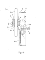
- FIG. 4 a further embodiment of an adjusting device 1 according to the invention is shown.
- the FIG. 4 illustrated actuator has some similarities with the in FIG. 1 shown embodiment and may be housed in a same housing 2.
- a drive shaft 21 is inserted through a drive element 3.
- the drive element 3 may, for. B. with a screw or z. B. worm gear (not shown) drive movements and drive torques transmitted to further transmission elements 10 a and 10 b of a transmission of the actuating device 1, which act on a drive wheel 9 of the transmission.
- the drive wheel 9 is connected to a push chain 4 in z. B. Reibkraft- or positive engagement and is provided for extending and retracting the push chain 4 through an opening 5.
- FIG. 5 a further embodiment of an adjusting device 1 according to the invention is shown, which has a relatively compact housing 2.
- a drive element 9 is mounted with an insertion opening 8.
- the drive element 9 is also intended to drive a push chain 4 directly and pushed out and retract at an opening 5 of the housing portion 2g.
- the drive element 9 may be for a non-positive or a interlocking interaction, in particular in a combination of both modes of action to be matched to the push chain 4.
- two guide elements 11 and 12 are mounted in the housing section 2g, with which the push chain 4 in the housing section 2g is guided fittingly on the drive element 9.
Landscapes
- Power-Operated Mechanisms For Wings (AREA)
Applications Claiming Priority (1)
| Application Number | Priority Date | Filing Date | Title |
|---|---|---|---|
| DE201420001171 DE202014001171U1 (de) | 2014-02-11 | 2014-02-11 | Stellvorrichtung für einen Flügel sowie Vorrichtung zur Einstellung von mehreren Flügeln |
Publications (1)
| Publication Number | Publication Date |
|---|---|
| EP2905409A1 true EP2905409A1 (fr) | 2015-08-12 |
Family
ID=50726388
Family Applications (1)
| Application Number | Title | Priority Date | Filing Date |
|---|---|---|---|
| EP14196892.5A Withdrawn EP2905409A1 (fr) | 2014-02-11 | 2014-12-09 | Dispositif de réglage pour une aile et dispositif de réglage de plusieurs ailes |
Country Status (2)
| Country | Link |
|---|---|
| EP (1) | EP2905409A1 (fr) |
| DE (2) | DE202014001171U1 (fr) |
Cited By (1)
| Publication number | Priority date | Publication date | Assignee | Title |
|---|---|---|---|---|
| WO2019096811A1 (fr) * | 2017-11-14 | 2019-05-23 | Geze Gmbh | Dispositif d'entraînement modulaire |
Families Citing this family (1)
| Publication number | Priority date | Publication date | Assignee | Title |
|---|---|---|---|---|
| DE102018104768A1 (de) * | 2018-03-02 | 2019-09-05 | Iwis Antriebssysteme Gmbh & Co. Kg | Aktuator mit rückensteifer Kette |
Citations (3)
| Publication number | Priority date | Publication date | Assignee | Title |
|---|---|---|---|---|
| US4014136A (en) * | 1974-07-18 | 1977-03-29 | Teleflex Morse Limited | Means for the opening and closing of angularly movable panels |
| DE10346861A1 (de) * | 2003-10-09 | 2005-05-04 | Stg Beikirch Industrieelektron | Ausstellvorrichtung |
| FR2909407A1 (fr) * | 2006-12-01 | 2008-06-06 | Window Automation Industry Srl | Actionneur electromecanique pour la manoeuvre d'un ouvrant et installation de fermeture comprenant un tel actionneur |
Family Cites Families (1)
| Publication number | Priority date | Publication date | Assignee | Title |
|---|---|---|---|---|
| DK135995A (da) * | 1995-12-01 | 1997-06-02 | Rasmussen Kann Ind As | Operator med mindst to udstillerelementer til åbning og lukning af svingbare vinduer |
-
2014
- 2014-02-11 DE DE201420001171 patent/DE202014001171U1/de not_active Expired - Lifetime
- 2014-12-09 DE DE102014118194.8A patent/DE102014118194A1/de not_active Withdrawn
- 2014-12-09 EP EP14196892.5A patent/EP2905409A1/fr not_active Withdrawn
Patent Citations (3)
| Publication number | Priority date | Publication date | Assignee | Title |
|---|---|---|---|---|
| US4014136A (en) * | 1974-07-18 | 1977-03-29 | Teleflex Morse Limited | Means for the opening and closing of angularly movable panels |
| DE10346861A1 (de) * | 2003-10-09 | 2005-05-04 | Stg Beikirch Industrieelektron | Ausstellvorrichtung |
| FR2909407A1 (fr) * | 2006-12-01 | 2008-06-06 | Window Automation Industry Srl | Actionneur electromecanique pour la manoeuvre d'un ouvrant et installation de fermeture comprenant un tel actionneur |
Cited By (1)
| Publication number | Priority date | Publication date | Assignee | Title |
|---|---|---|---|---|
| WO2019096811A1 (fr) * | 2017-11-14 | 2019-05-23 | Geze Gmbh | Dispositif d'entraînement modulaire |
Also Published As
| Publication number | Publication date |
|---|---|
| DE202014001171U1 (de) | 2014-04-29 |
| DE102014118194A1 (de) | 2015-08-13 |
Similar Documents
| Publication | Publication Date | Title |
|---|---|---|
| DE4131762C2 (de) | Betätigungsvorrichtung für einen Flügel eines Fensters, einer Tür, einer Lüftungsklappe oder dergleichen | |
| EP3245373B1 (fr) | Entraînement à chaîne en poussée | |
| DE202011109983U1 (de) | Bandantrieb für Zug- und Druckbeanspruchung | |
| DE4407276A1 (de) | Ausstellvorrichtung für einen Flügel eines Fensters, Lüftungsklappe, Lichtkuppel, Tür oder dergleichen sowie Antrieb zur Bewegung zweier Bauteile relativ zueinander | |
| EP2325430A2 (fr) | Entraînement de porte pour une porte d'un véhicule pour le transport de personnes | |
| DE3305272A1 (de) | Befestigungsplatte fuer scharnierarm | |
| EP2905409A1 (fr) | Dispositif de réglage pour une aile et dispositif de réglage de plusieurs ailes | |
| EP2009215B1 (fr) | Dispositif de détection pour un dispositif d'entraînement des portes ou fenêtres | |
| EP1614844A2 (fr) | Dispositif d'articulation | |
| EP3670805A1 (fr) | Ferrures de terminaison pour chaîne de poussée | |
| EP1860266B1 (fr) | Agencement d'un dispositif d'actionnement d'articulations, en particulier pour un battant de fenêtre, un cadre ou un globe d'éclairage | |
| DE4210523A1 (de) | Kombinierter Schub- und Zugantrieb | |
| EP0596085B1 (fr) | Dispositif d'actionnement pour bandes de rideau | |
| EP4105416B1 (fr) | Dispositif de blocage pour une porte bâtie de deux côtés | |
| EP1437475B1 (fr) | Fenêtre ou porte avec dispositif d'entraînement | |
| DE202005016021U1 (de) | Gelenkmechanismus | |
| EP1555379A1 (fr) | Rideau à lammes | |
| EP2818618B1 (fr) | Dispositif de régulation de la séquence de fermeture d'une installation de porte rotative à deux battants | |
| DE10300653A1 (de) | Fenster oder Tür mit Antriebsvorrichtung | |
| EP1862631A2 (fr) | Dispositif de commande destiné au réglage motorisé d'un élément de fermeture d'un véhicule automobile | |
| EP1908892B1 (fr) | Lucarne | |
| DE102019119262B3 (de) | Scharnier für eine Fahrzeugtür | |
| DE10201317B4 (de) | Motorisch betriebene oder betreibbare Scherenanordnung zur Betätigung eines Oberlichtflügels gegenüber einem Blendrahmen | |
| EP3771795B1 (fr) | Disposition de porte dotée d'une unité de réglage | |
| EP1637684B1 (fr) | Mécanisme d'entraînement pour systèmes d'accès et de sortie, notamment portes de véhicules sur rails |
Legal Events
| Date | Code | Title | Description |
|---|---|---|---|
| PUAI | Public reference made under article 153(3) epc to a published international application that has entered the european phase |
Free format text: ORIGINAL CODE: 0009012 |
|
| AK | Designated contracting states |
Kind code of ref document: A1 Designated state(s): AL AT BE BG CH CY CZ DE DK EE ES FI FR GB GR HR HU IE IS IT LI LT LU LV MC MK MT NL NO PL PT RO RS SE SI SK SM TR |
|
| AX | Request for extension of the european patent |
Extension state: BA ME |
|
| 17P | Request for examination filed |
Effective date: 20151103 |
|
| RBV | Designated contracting states (corrected) |
Designated state(s): AL AT BE BG CH CY CZ DE DK EE ES FI FR GB GR HR HU IE IS IT LI LT LU LV MC MK MT NL NO PL PT RO RS SE SI SK SM TR |
|
| 17Q | First examination report despatched |
Effective date: 20180423 |
|
| STAA | Information on the status of an ep patent application or granted ep patent |
Free format text: STATUS: THE APPLICATION IS DEEMED TO BE WITHDRAWN |
|
| 18D | Application deemed to be withdrawn |
Effective date: 20180904 |