EP3369687A1 - Elevator device - Google Patents
Elevator device Download PDFInfo
- Publication number
- EP3369687A1 EP3369687A1 EP15907188.5A EP15907188A EP3369687A1 EP 3369687 A1 EP3369687 A1 EP 3369687A1 EP 15907188 A EP15907188 A EP 15907188A EP 3369687 A1 EP3369687 A1 EP 3369687A1
- Authority
- EP
- European Patent Office
- Prior art keywords
- brake
- linear groove
- disc
- brake pad
- center
- Prior art date
- Legal status (The legal status is an assumption and is not a legal conclusion. Google has not performed a legal analysis and makes no representation as to the accuracy of the status listed.)
- Pending
Links
- 230000005484 gravity Effects 0.000 description 12
- 230000000694 effects Effects 0.000 description 4
- 239000000463 material Substances 0.000 description 2
- 239000011347 resin Substances 0.000 description 2
- 229920005989 resin Polymers 0.000 description 2
- 230000015572 biosynthetic process Effects 0.000 description 1
- 238000010586 diagram Methods 0.000 description 1
- 230000005281 excited state Effects 0.000 description 1
- 230000004048 modification Effects 0.000 description 1
- 238000012986 modification Methods 0.000 description 1
Images


Classifications
-
- B—PERFORMING OPERATIONS; TRANSPORTING
- B66—HOISTING; LIFTING; HAULING
- B66B—ELEVATORS; ESCALATORS OR MOVING WALKWAYS
- B66B5/00—Applications of checking, fault-correcting, or safety devices in elevators
- B66B5/02—Applications of checking, fault-correcting, or safety devices in elevators responsive to abnormal operating conditions
-
- B—PERFORMING OPERATIONS; TRANSPORTING
- B66—HOISTING; LIFTING; HAULING
- B66B—ELEVATORS; ESCALATORS OR MOVING WALKWAYS
- B66B11/00—Main component parts of lifts in, or associated with, buildings or other structures
- B66B11/04—Driving gear ; Details thereof, e.g. seals
- B66B11/08—Driving gear ; Details thereof, e.g. seals with hoisting rope or cable operated by frictional engagement with a winding drum or sheave
-
- F—MECHANICAL ENGINEERING; LIGHTING; HEATING; WEAPONS; BLASTING
- F16—ENGINEERING ELEMENTS AND UNITS; GENERAL MEASURES FOR PRODUCING AND MAINTAINING EFFECTIVE FUNCTIONING OF MACHINES OR INSTALLATIONS; THERMAL INSULATION IN GENERAL
- F16D—COUPLINGS FOR TRANSMITTING ROTATION; CLUTCHES; BRAKES
- F16D55/00—Brakes with substantially-radial braking surfaces pressed together in axial direction, e.g. disc brakes
- F16D55/02—Brakes with substantially-radial braking surfaces pressed together in axial direction, e.g. disc brakes with axially-movable discs or pads pressed against axially-located rotating members
- F16D55/04—Brakes with substantially-radial braking surfaces pressed together in axial direction, e.g. disc brakes with axially-movable discs or pads pressed against axially-located rotating members by moving discs or pads away from one another against radial walls of drums or cylinders
- F16D55/06—Brakes with substantially-radial braking surfaces pressed together in axial direction, e.g. disc brakes with axially-movable discs or pads pressed against axially-located rotating members by moving discs or pads away from one another against radial walls of drums or cylinders without self-tightening action
-
- F—MECHANICAL ENGINEERING; LIGHTING; HEATING; WEAPONS; BLASTING
- F16—ENGINEERING ELEMENTS AND UNITS; GENERAL MEASURES FOR PRODUCING AND MAINTAINING EFFECTIVE FUNCTIONING OF MACHINES OR INSTALLATIONS; THERMAL INSULATION IN GENERAL
- F16D—COUPLINGS FOR TRANSMITTING ROTATION; CLUTCHES; BRAKES
- F16D65/00—Parts or details
- F16D65/02—Braking members; Mounting thereof
- F16D65/04—Bands, shoes or pads; Pivots or supporting members therefor
- F16D65/092—Bands, shoes or pads; Pivots or supporting members therefor for axially-engaging brakes, e.g. disc brakes
Definitions
- the present invention relates to an elevator device, and in particular to an elevator device suitable for an elevator device with a disc brake system.
- PTL 1 An elevator device with a disc brake system is disclosed in PTL 1.
- PTL 1 discloses a brake system for an elevator device, including a disc rotating with a rotor of a device, a plurality of pads each facing the disc, and a pressing mechanism for pressing the pads against the surface of the disc.
- PTL 1 however, only discloses a brake system for an elevator device having the configuration as described above, and PTLs 2 to 4 discloses disc brake systems for automobiles.
- gas is likely to be generated from resin used for part of the material of a brake pad owing to the rise in the high temperature, and wear is likely to occur, which leads to such a phenomenon as generation of much wear debris. Since such gas and wear debris present between the frictional faces make frictional characteristics less stable, gas and wear debris generated during braking need to be removed so as to be present between the frictional faces as little as possible in order to stabilize the frictional characteristics.
- the present invention has been made in view of the aforementioned circumstances, and an object thereof is to provide an elevator device including a disc brake system capable of quickly removing gas and wear debris generated from the vicinity of the center of a brake pad without lowering the strength of the brake pad, which provides stable frictional characteristics.
- an elevator device of the present invention includes: a hoisting machine connected via a drive motor and a rotating shaft, a main rope being wound around the hoisting machine; a car connected with one end of the main rope wound around the hoisting machine and a balance weight connected with the other end of the main rope; and a disc brake system including a brake disc connected with a rotating shaft of the hoisting machine, and a brake pad pressed against the brake disc to apply braking force to stop the hoisting machine to bring the car and the balance weight into a stopped state, wherein the brake pad of the disc brake system has one linear groove formed to extend through a center of the brake pad, and two linear grooves formed to be perpendicular to the one linear groove and face each other with the center of the brake pad therebetween at positions away from the center, and either the one linear grooves or the two linear groove is/are formed along a sliding contact direction of the brake pad and the brake disc.
- the present invention achieves an elevator device including a disc brake system capable of quickly removing gas and wear debris generated from the vicinity of the center of a brake pad without lowering the strength of the brake pad, which provides stable frictional characteristics.
- FIG. 1 illustrates an overall configuration of a first embodiment of an elevator device of the present invention.
- a hoisting machine 3 is installed in a machine room 2 formed on a top of a hoistway 1, and a main rope (rope) 4 is wound around a sheave of the hoisting machine 3.
- One end of the main rope 4 is connected to a car 5, and the other end of the main rope 4 is connected with a balance weight 6.
- FIGS. 2 and 3 A detailed configuration of the hoisting machine 3 is illustrated in FIGS. 2 and 3 .
- the hoisting machine 3 is installed on a fixed base 7 fixed to a floor of the machine room 2, and a drive motor 8 and bearing stands 9 and 10 are fixed to the fixed base 7.
- the bearing stands 9 and 10 rotatably supports a rotating shaft 11 that transmits driving force of the drive motor 8 to the hoisting machine 3.
- a sheave 13 and a brake disc 14 having a diameter larger than that of the sheave 13 are coaxially fixed to the rotating shaft 11 that drives the hoisting machine 3.
- disc brake systems 15 and 16 are attached to the bearing stand 10 at two positions, lateral to each other, of a support arm 19.
- the disc brake systems 15 and 16 are mounted on a horizontal line through the center of the brake disc 14.
- the disc brake systems 15 and 16 have the same configuration, and each include an actuator including an electromagnetic coil and a spring, which are not illustrated.
- the disc brake systems 15 and 16 are configured such that, after the drive motor 8 is powered off, the disc brake systems 15 and 16 become a non-excited state and press brake shoes 17 and 18 called calipers against respective faces of the brake disc 14 with elastic force of the springs to generate braking force on the brake disc 14.
- FIGS. 4 and 5 A detailed configuration of the disc brake system 16 is illustrated in FIGS. 4 and 5 .
- the disc brake system 16 is attached, with a plurality of bolts 20 or the like, to the support arm 19 of the bearing stand 10 fixed to the fixed base 7.
- the disc brake system 16 has a cylindrical outer shape, while the brake shoes 17 and 18 have rectangular outer shapes as will be described later.
- the brake shoes 17 and 18 each have a brake pad 21, the brake pads 21 facing braking contact faces on respective sides of the brake disc 14.
- the brake shoe 18 is fixed to a brake body 22 by tightening of a stroke adjusting bolt 23 for adjusting an operating distance in braking.
- the brake shoe 17 is movable in a braking direction (a lateral direction in FIG. 4 ) coming into contact with the brake disc 14 by an actuator 24 including an electromagnetic coil and a spring, which are not illustrated.
- an end portion of the driving rod 25 of the actuator 24 is turnably connected to an engagement portion (having a recessed shape) 26 of the brake shoe 17.
- a spring member 27 for attachment is attached to an outer circumference of the end portion of the driving rod 25, and bent portions at ends of the spring member 27 for attachment are engaged with pins 28 attached to the brake shoe 17.
- a plate 30 having cutouts 29 engaged with the pins 28 is positioned on a side face of the brake shoe 17, and is fixed to the brake shoe 17 with set screws 31. Retaining split pins 32 are inserted in the pins 28 to hold the connection of the brake shoe 17, the spring member 27 for attachment, and the plate 30.
- the brake shoe 17 side is turnably (swingably) held by the end portion of the driving rod 25.
- the attachment structure of the brake shoe 18 attached to and end of the stroke adjusting bolt 23 illustrated in FIG. 4 is substantially the same as that of the brake shoe 17.
- the brake shoe 17 In braking, the brake shoe 17 is pressed toward the brake disc 14 by the spring, which is not illustrated, included in the actuator 24 illustrated in FIG. 4 via the driving rod 25.
- the pair of brake shoes 17 and 18 located on the respective sides of the brake disc 14 press the respective brake pads 21 to the brake disc 14 to apply braking force, stop the hoisting machine 3 illustrated in FIG. 1 , and bring the car 5 and the balance weight 6 into a stopped state.
- FIGS. 6 and 7 illustrate enlarged views of the brake pad 21 of the brake shoe 17.
- FIGS. 6 and 7 illustrate a sliding contact face of the brake pad 21 in sliding contact with the brake disc 14, in which an arrow 12 indicates a sliding contact direction (a tangent direction of the circumference) of the brake pad 21 and the brake disc 14.
- the brake pad 21 has a quadrangular shape, having a first linear groove 33A and a second linear groove 33B formed substantially along the sliding contact direction with respect to the brake disc 14 (the vertical direction or gravity direction in the present embodiment), and a third linear groove 33C formed in a direction substantially perpendicular to the sliding contact direction 12.
- the center of the brake pad 21 is represented by a reference numeral 35, and the first linear groove 33A and the second linear groove 33B are formed in parallel to each other avoiding the center 35 of the brake pad 21 with a distance therebetween, which will be described in detail below, on opposite sides of the center 35 of the brake pad 21, while the third linear groove 33C is formed at a position substantially through the center 35 of the brake pad 21.
- linear grooves 33A, 33B, and 33C intersect with each other at positions off the center 35 of the brake pad 21, and the grooves communicate with each other at the intersections. In other words, a groove structure in which the linear grooves 33A, 33B, and 33C intersect with each other at the center 35 of the brake pad 21 is avoided.
- the width dimension of the brake pad 21 is represented by L and the distance from the center 35 of the brake pad 21 to the first linear groove 33A or the second linear groove 33B is represented by L1
- the first linear groove 33A and second linear groove 33B are formed to meet a condition of 0.1L ⁇ L1 ⁇ 0.25L.
- the amount of braking energy is very large.
- the temperature at sliding contact faces of the brake disc 14 and the brake pad 21 becomes very high by frictional heat generated during braking.
- the time taken until stopping after braking is several seconds to several tens of seconds, gas is generated from resin used for part of the material of the brake pad 21 owing to the rise in the temperature, and wear debris is generated.
- the vicinity of the center 35 of the brake pad 21 is pressed most hard, gas is generated and wear debris is generated near the center 35 of the brake pad 21.
- the third linear groove 33C is formed through substantially the center 35 of the brake pad 21, the gas generated near the center 35 of the brake pad 21, in particular, is quickly discharged.
- the third linear groove 33C extends in the direction perpendicular to the sliding contact direction 12 of the brake disc 14 and the brake pad 21, wear debris that is likely to be generated from the third linear groove 33C is quickly discharged through the first linear groove 33A and the second linear groove 33B. Specifically, as illustrated in FIG.
- first linear groove 33A and the second linear groove 33B are formed avoiding the center 35 of the brake pad 21 and communicating with the third linear groove 33C extending through substantially the center 35 of the brake pad 21, wear debris generated from the vicinity of the center 35 of the brake pad 21, in particular, is removed as described above without lowering the strength of the brake pad 21 at the vicinity of the center 35 of the brake pad 21 that is pressed most hard.
- the position of the center 35 of the brake pad 21 between the two grooves, that is, the first linear groove 33A and the second linear groove 33B allows the brake pad 21 to have a large contact face near the center 35 of the brake pad 21, which increases the strength.
- the third linear groove 33C extending through substantially the center 35 of the brake pad 21 allows gas generated from the large contact face near the center 35 of the brake pad 21 to be quickly discharged.
- gas generated from the contact face near the center 35 of the brake pad 21 is discharged and wear debris is removed while the strength is maintained, which provides an elevator device having more stable frictional characteristics of the vicinity of the center 35 of the brake pad 21 with respect to the brake disc 14 and having the disc brake systems 15 and 16 with more stable braking characteristics than a configuration as in the related art in which wear debris is likely to be accumulated.
- FIG. 8 illustrates an enlarged view of another example of a brake pad 21 of a brake shoe 17 as a second embodiment of an elevator device according to the present invention.
- the brake pad 21 in the present embodiment has a rectangular shape that is long in the sliding contact direction 12 indicated by an arrow, and has one first linear groove 34A formed through substantially the center 35 of the brake pad 21 and substantially along the sliding contact direction 12 of the brake pad 21 and the brake disc 14, and two grooves, which are a second linear groove 34B and a third linear groove 34C, formed in a direction substantially perpendicular to the sliding contact direction 12 at positions with the center 35 of the brake pad 21 therebetween and avoiding the center 35 of the brake pad 21.
- These linear grooves 34A, 34B, and 34C communicate with each other at intersections avoiding the center 35 of the brake pad 21.
- the second linear groove 34B and the third linear groove 34C are formed to meet a condition of 0.1H ⁇ H1 ⁇ 0.25H.
- first linear groove 34A is formed avoiding intersecting with the second linear groove 34B and the third linear groove 34C at the center 35 of the brake pad 21 and to extend through substantially the center 35 of the brake pad 21, gas generated from the vicinity of the center 35 of the brake pad 21, in particular, is quickly discharged.
- wear debris generated from the second linear groove 34B and the third linear groove 34C perpendicular to the sliding contact faces of the brake disc 14 and the brake pad 21 is quickly discharged through the first linear groove 34A. Specifically, as illustrated in FIG.
- first linear groove 34A is one and the second linear groove 34B and the third linear groove 34C are formed avoiding the center 35 of the brake pad 21, wear debris generated from the vicinity of the center 35 of the brake pad 21, in particular, falls in the gravity direction and is removed as described above without lowering the strength of the brake pad 21 at the vicinity of the center 35 of the brake pad 21 that is pressed most hard.
- the formation of the two grooves, that is, the second linear groove 34B and the third linear groove 34C such that the center 35 of the brake pad 21 is positioned between the second linear groove 34B and the third linear groove 34C allows the brake pad 21 to have a large contact face near the center 35, which increases the strength.
- the first linear groove 34A extending through substantially the center 35 of the brake pad 21 allows gas generated from the large contact face near the center 35 of the brake pad 21 to be quickly discharged.
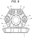
- FIG. 9 illustrates an enlarged view of a hoisting machine included in a third embodiment of an elevator device according to the present invention.
- disc brake systems include disc brake systems 15 and 16 arranged on a horizontal line through the center of a brake disc 14, and disc brake systems 36 and 37 mounted above the disc brake systems 15 and 16. Brake pads 21 of all these disc brake systems 15, 16, 36, and 37 have the configuration in the first embodiment illustrated in FIG.
- first linear groove 33A and a second linear groove 33B formed to extend in the sliding contact direction 12 of the brake pad 21 and the brake disc 14, and one third linear groove 33C formed to intersect with the first linear groove 33A and the second linear groove 33B in such a manner as to communicate with the first linear groove 33A and the second linear groove 33B, and extend in a direction perpendicular to the sliding contact direction 12 and through the center 35 of the brake pad 21, in which the intersections of the first linear groove 33A and the second linear groove 33B with the third linear groove 33C are positioned off the center 35 of the brake pad 21.
- first linear groove 33A and the second linear groove 33B are formed to extend in the vertical direction (gravity direction) in the disc brake systems 15 and 16, while the first linear groove 33C is formed to extend in the sliding contact direction 12 but to be tilted with respect to the vertical direction (gravity direction) in the disc brake systems 36 and 37.
- the brake pads 21 of all the disc brake systems 15, 16, 36, and 37 may each have the configuration of the first embodiment illustrated in FIG. 8 described above, the is, the configuration having one first linear groove 34A formed to extend in the sliding contact direction 12 of the brake pad 21 and the brake disc 14 and through the center 36 of the brake pad 21, and the second linear groove 34B and the third linear groove 34C formed to intersect with the first linear groove 34A in such a manner to communicate with the first linear groove 34A and extend in the direction perpendicular to the sliding contact direction 12, in which the intersections of the first linear groove 34A with the second linear groove 34B and the third linear groove 34C are positioned off the center 35 of the brake pad 21, the first linear groove 34A is formed to extend in the vertical direction (gravity direction) in the disc brake systems 15 and 16 while the second linear groove 34B and the third linear groove 34C extending in the sliding contact direction 12 are tilted with respect to the vertical direction (gravity direction) in the disc brake systems 36 and 37.
- the configurations of the brake pads 21 of the disc brake systems 15 and 16 and the disc brake systems 36 and 37 in the first embodiment and those in the second embodiments may be combined.
- the brake pads 21 of the disc brake systems 15 and 16 may have the configuration in the first embodiment (the configuration in FIG. 6 ) or the configuration in the second embodiment (the configuration in FIG. 8 ), and the disc brake systems 36 and 37 may have the configuration in the second embodiment or the configuration in the first embodiment, or alternatively, three disc brake systems 15, 16, and 36 may have the configuration in the first embodiment (the configuration in FIG. 6 ) or the configuration in the second embodiment (the configuration in FIG. 8 ), and the remaining one disc brake system 37 may have the configuration in the second embodiment or the configuration in the first embodiment.
- the brake pads 21 used in the disc brake systems 36 and 37 may have various configurations.
- the first linear groove 33A, the second linear groove 33B or 34A may be used in vertical direction similarly to the brake pads 21 of the configuration in in the first embodiment ( FIG. 6 ) and the configuration in the second embodiment ( FIG. 8 ) described above, or the first linear groove 33A, the second linear groove 33B, or the first linear groove 34A may be used in a different direction that substantially corresponds to the sliding contact direction 12 at the mounting positions of the disc brake systems 36 and 37.
- the first linear groove 33A, the second linear groove 33B, or the first linear groove 34A is inclined as compared to that in the disc brake systems 15 and 16.
- the brake pad 21 of the disc brake system 36 is mounted at a position turned by 45 degrees in the clockwise direction from the brake pad 21 illustrated in FIG. 6 .
- the first linear groove 33A and the second linear groove 33B formed in the sliding contact direction 12 is inclined with respect to the gravity direction, however, since the third linear groove 33C communicating with the first linear groove 33A and the second linear groove 33B is also formed to be inclined by 45 degrees with respect to the gravity direction, wear debris is discharged through the third linear groove 33C, and substantially the same effects can be expected to a greater or less extent.
- one third linear groove 33C or first linear groove 34A is formed to extend through substantially the center 35 of the brake pad 21, and two other grooves, which are a first linear groove 33A and a second linear groove 33B or a second linear groove 34B and a third linear groove 34C, are formed perpendicularly to the third linear groove 33C or the first linear groove 34A and arranged to face each other with the center 35 of the brake pad 21 therebetween at positions away from the center 35 of the brake pad 21.
- the linear grooves intersect with and communicate with each other avoiding the center 35 of the brake pad 21, which allows wear debris and gas generated from the vicinity of the center 35 of the brake pad 21, in particular, to be removed without lowering the strength of the brake pad 21 in the vicinity of the center 35 of the brake pad 21 pressed most hard.
- an elevator device having stable frictional characteristics of the vicinity of the center 35 of the brake pad 21 with respect to the brake disc 14 and having the disc brake systems with stable braking characteristics is provided.
- At least one disc brake system 16 is positioned on a horizontal line through substantially the center 35 of the brake disc 14, and the brake pad 21 of the disc brake system 16 has two grooves, which are the first linear groove 33A and the second linear groove 33B, formed to extend in the sliding contact direction 12 of the brake pad 21 and the brake disc 14, and the third linear groove 33C formed to intersect with the first linear groove 33A and the second linear groove 33B in such a manner to communicate with the first linear groove 33A and the second linear groove 33B and extend in the direction substantially perpendicular to the sliding contact direction 12, in which the intersections of the first linear groove 33A and the second linear groove 33B with the third linear groove 33C are positioned off the center 35 of the brake pad 21.
- At least one disc brake system 16 is positioned on a horizontal line through substantially the center 35 of the brake disc 14, and the brake pad 21 of the disc brake system 16 has one first linear groove 34A formed to extend in the sliding contact direction 12 of the brake pad 21 and the brake disc 14, and the second linear groove 34B and the third linear groove 34C formed to intersect with the first linear groove 34A in such a manner to communicate with the first linear groove 34A and extend in the direction substantially perpendicular to the sliding contact direction 12, in which the intersections of the first linear groove 34A with the second linear groove 34B and the third linear groove 34C are positioned off the center 35 of the brake pad 21.
- the present invention achieves an elevator device including a disc brake system capable of quickly removing gas and wear debris generated from the vicinity of the center of a brake pad without lowering the strength of the brake pad, which provides stable frictional characteristics.
- the present invention is not limited to the embodiments described above, but includes various modifications.
- the embodiments described above are described in detail for simple explanation of the present invention, and are not necessarily limited to those including all the features described above.
- some of features of an embodiment may be replaced with features of another embodiment, and a feature of an embodiment may be added to features of another embodiment.
- Some of the features in the embodiments may additionally include other features, may be deleted, or may be replaced with other features.
Abstract
Description
- The present invention relates to an elevator device, and in particular to an elevator device suitable for an elevator device with a disc brake system.
- An elevator device with a disc brake system is disclosed in
PTL 1.PTL 1 discloses a brake system for an elevator device, including a disc rotating with a rotor of a device, a plurality of pads each facing the disc, and a pressing mechanism for pressing the pads against the surface of the disc. - In addition, disc brake systems for automobiles are disclosed in
PTL 2,PTL 3, andPTL 4. In these patent literatures, a plurality of grooves are formed on a brake pad. -
- PTL 1:
JP 2012-225513 A - PTL 2:
JP 2007-24286 A - PTL 3:
JP 2014-70651 A - PTL 4:
JP 2015-10635 A -
PTL 1, however, only discloses a brake system for an elevator device having the configuration as described above, andPTLs 2 to 4 discloses disc brake systems for automobiles. - Typically, since the total mass of a car, a balance weight, and a rope to be stopped by a disc brake system is large in an elevator device as compared to an automobile, and since the velocity is also high particularly in a high-speed elevator, the amount of braking energy is very large, frictional heat generated during braking thus makes the temperature at frictional faces of the disc and the brake pad very high, and the time taken until stopping after braking is several seconds to several tens of seconds.
- Furthermore, in a disc brake system for an elevator device, gas is likely to be generated from resin used for part of the material of a brake pad owing to the rise in the high temperature, and wear is likely to occur, which leads to such a phenomenon as generation of much wear debris. Since such gas and wear debris present between the frictional faces make frictional characteristics less stable, gas and wear debris generated during braking need to be removed so as to be present between the frictional faces as little as possible in order to stabilize the frictional characteristics.
- The present invention has been made in view of the aforementioned circumstances, and an object thereof is to provide an elevator device including a disc brake system capable of quickly removing gas and wear debris generated from the vicinity of the center of a brake pad without lowering the strength of the brake pad, which provides stable frictional characteristics.
- To achieve the aforementioned object, an elevator device of the present invention includes: a hoisting machine connected via a drive motor and a rotating shaft, a main rope being wound around the hoisting machine; a car connected with one end of the main rope wound around the hoisting machine and a balance weight connected with the other end of the main rope; and a disc brake system including a brake disc connected with a rotating shaft of the hoisting machine, and a brake pad pressed against the brake disc to apply braking force to stop the hoisting machine to bring the car and the balance weight into a stopped state, wherein the brake pad of the disc brake system has one linear groove formed to extend through a center of the brake pad, and two linear grooves formed to be perpendicular to the one linear groove and face each other with the center of the brake pad therebetween at positions away from the center, and either the one linear grooves or the two linear groove is/are formed along a sliding contact direction of the brake pad and the brake disc.
- The present invention achieves an elevator device including a disc brake system capable of quickly removing gas and wear debris generated from the vicinity of the center of a brake pad without lowering the strength of the brake pad, which provides stable frictional characteristics.
-
- [
FIG. 1] FIG. 1 is a schematic configuration diagram illustrating a first embodiment of an elevator device according to the present invention. - [
FIG. 2] FIG. 2 is an enlarged view of a hoisting machine included in the first embodiment of the elevator device according to the present invention. - [
FIG. 3] FIG. 3 is a side view of the hoisting machine illustrated inFIG. 2 . - [
FIG. 4] FIG. 4 is an enlarged plan view of a disc brake system included in the hoisting machine illustrated inFIG. 3 . - [
FIG. 5] FIG. 5 is an enlarged view of a main part of the disc brake system illustrated inFIG. 4 . - [
FIG. 6] FIG. 6 is an enlarged front view of a brake pad of the disc brake system illustrated inFIG. 4 . - [
FIG. 7] FIG. 7 is a side view of the brake pad illustrated inFIG. 6 . - [
FIG. 8] FIG. 8 is an enlarged front view of another example of a brake pad as a second embodiment of an elevator device according to the present invention. - [
FIG. 9] FIG. 9 is an enlarged view of a hoisting machine included in a third embodiment of an elevator device according to the present invention. - An elevator device according to the present invention will be described below with reference to illustrated embodiments. In the figures, the same reference numerals are used for corresponding components.
-
FIG. 1 illustrates an overall configuration of a first embodiment of an elevator device of the present invention. - As illustrated in
FIG. 1 , a hoistingmachine 3 is installed in amachine room 2 formed on a top of ahoistway 1, and a main rope (rope) 4 is wound around a sheave of the hoistingmachine 3. One end of themain rope 4 is connected to acar 5, and the other end of themain rope 4 is connected with abalance weight 6. - A detailed configuration of the hoisting
machine 3 is illustrated inFIGS. 2 and3 . - As illustrated in
FIGS. 2 and3 , the hoistingmachine 3 is installed on afixed base 7 fixed to a floor of themachine room 2, and adrive motor 8 andbearing stands fixed base 7. The bearing stands 9 and 10 rotatably supports a rotatingshaft 11 that transmits driving force of thedrive motor 8 to the hoistingmachine 3. Asheave 13 and abrake disc 14 having a diameter larger than that of thesheave 13 are coaxially fixed to the rotatingshaft 11 that drives the hoistingmachine 3. - In addition,
disc brake systems bearing stand 10 at two positions, lateral to each other, of asupport arm 19. Thedisc brake systems brake disc 14. - The
disc brake systems disc brake systems drive motor 8 is powered off, thedisc brake systems press brake shoes brake disc 14 with elastic force of the springs to generate braking force on thebrake disc 14. - A detailed configuration of the
disc brake system 16 is illustrated inFIGS. 4 and5 . - The
disc brake system 16 is attached, with a plurality ofbolts 20 or the like, to thesupport arm 19 of thebearing stand 10 fixed to thefixed base 7. Thedisc brake system 16 has a cylindrical outer shape, while thebrake shoes - The
brake shoes brake pad 21, thebrake pads 21 facing braking contact faces on respective sides of thebrake disc 14. Thebrake shoe 18 is fixed to abrake body 22 by tightening of a stroke adjustingbolt 23 for adjusting an operating distance in braking. In contrast, thebrake shoe 17 is movable in a braking direction (a lateral direction inFIG. 4 ) coming into contact with thebrake disc 14 by anactuator 24 including an electromagnetic coil and a spring, which are not illustrated. - Since the
brake shoes brake shoe 17 attached to adriving rod 25 of theactuator 24 will be described herein. - As illustrated in
FIG. 5 , an end portion of thedriving rod 25 of theactuator 24 is turnably connected to an engagement portion (having a recessed shape) 26 of thebrake shoe 17. Aspring member 27 for attachment is attached to an outer circumference of the end portion of thedriving rod 25, and bent portions at ends of thespring member 27 for attachment are engaged withpins 28 attached to thebrake shoe 17. Aplate 30 havingcutouts 29 engaged with thepins 28 is positioned on a side face of thebrake shoe 17, and is fixed to thebrake shoe 17 with setscrews 31. Retainingsplit pins 32 are inserted in thepins 28 to hold the connection of thebrake shoe 17, thespring member 27 for attachment, and theplate 30. As described above, thebrake shoe 17 side is turnably (swingably) held by the end portion of thedriving rod 25. - The attachment structure of the
brake shoe 18 attached to and end of thestroke adjusting bolt 23 illustrated inFIG. 4 is substantially the same as that of thebrake shoe 17. - In braking, the
brake shoe 17 is pressed toward thebrake disc 14 by the spring, which is not illustrated, included in theactuator 24 illustrated inFIG. 4 via thedriving rod 25. As a result, the pair ofbrake shoes brake disc 14 press therespective brake pads 21 to thebrake disc 14 to apply braking force, stop the hoistingmachine 3 illustrated inFIG. 1 , and bring thecar 5 and thebalance weight 6 into a stopped state. -
FIGS. 6 and7 illustrate enlarged views of thebrake pad 21 of thebrake shoe 17. - Since the
brake shoe 17 and thebrake shoe 18 have the same configuration, thebrake pad 21 of thebrake shoe 17 will be described herein.FIGS. 6 and7 illustrate a sliding contact face of thebrake pad 21 in sliding contact with thebrake disc 14, in which anarrow 12 indicates a sliding contact direction (a tangent direction of the circumference) of thebrake pad 21 and thebrake disc 14. - As illustrated in
FIG. 6 , thebrake pad 21 has a quadrangular shape, having a firstlinear groove 33A and a secondlinear groove 33B formed substantially along the sliding contact direction with respect to the brake disc 14 (the vertical direction or gravity direction in the present embodiment), and a thirdlinear groove 33C formed in a direction substantially perpendicular to the slidingcontact direction 12. - In addition, in the present embodiment, the center of the
brake pad 21 is represented by areference numeral 35, and the firstlinear groove 33A and the secondlinear groove 33B are formed in parallel to each other avoiding thecenter 35 of thebrake pad 21 with a distance therebetween, which will be described in detail below, on opposite sides of thecenter 35 of thebrake pad 21, while the thirdlinear groove 33C is formed at a position substantially through thecenter 35 of thebrake pad 21. - These
linear grooves center 35 of thebrake pad 21, and the grooves communicate with each other at the intersections. In other words, a groove structure in which thelinear grooves center 35 of thebrake pad 21 is avoided. - When the width dimension of the
brake pad 21 is represented by L and the distance from thecenter 35 of thebrake pad 21 to the firstlinear groove 33A or the secondlinear groove 33B is represented by L1, the firstlinear groove 33A and secondlinear groove 33B are formed to meet a condition of 0.1L ≤ L1 ≤ 0.25L. - As described above, since a total mass of the
car 5, thebalance weight 6, and themain rope 4 to be stopped by thedisc brake systems brake disc 14 and thebrake pad 21 becomes very high by frictional heat generated during braking. In addition, the time taken until stopping after braking is several seconds to several tens of seconds, gas is generated from resin used for part of the material of thebrake pad 21 owing to the rise in the temperature, and wear debris is generated. In particular, in the case of therectangular brake pad 21, since the vicinity of thecenter 35 of thebrake pad 21 is pressed most hard, gas is generated and wear debris is generated near thecenter 35 of thebrake pad 21. - In the present embodiment, however, since the third
linear groove 33C is formed through substantially thecenter 35 of thebrake pad 21, the gas generated near thecenter 35 of thebrake pad 21, in particular, is quickly discharged. In addition, since the thirdlinear groove 33C extends in the direction perpendicular to the slidingcontact direction 12 of thebrake disc 14 and thebrake pad 21, wear debris that is likely to be generated from the thirdlinear groove 33C is quickly discharged through the firstlinear groove 33A and the secondlinear groove 33B. Specifically, as illustrated inFIG. 2 , in a system in which thedisc brake systems brake disc 14, since the direction in which the firstlinear groove 33A and the secondlinear groove 33B are formed is the vertical direction, that is, the gravity direction, wear debris is quickly discharged downward through the firstlinear groove 33A and the secondlinear groove 33B and removed. - Furthermore, since the first
linear groove 33A and the secondlinear groove 33B are formed avoiding thecenter 35 of thebrake pad 21 and communicating with the thirdlinear groove 33C extending through substantially thecenter 35 of thebrake pad 21, wear debris generated from the vicinity of thecenter 35 of thebrake pad 21, in particular, is removed as described above without lowering the strength of thebrake pad 21 at the vicinity of thecenter 35 of thebrake pad 21 that is pressed most hard. In particular, the position of thecenter 35 of thebrake pad 21 between the two grooves, that is, the firstlinear groove 33A and the secondlinear groove 33B allows thebrake pad 21 to have a large contact face near thecenter 35 of thebrake pad 21, which increases the strength. In addition, the thirdlinear groove 33C extending through substantially thecenter 35 of thebrake pad 21 allows gas generated from the large contact face near thecenter 35 of thebrake pad 21 to be quickly discharged. - With the configuration of the present embodiment described above, gas generated from the contact face near the
center 35 of thebrake pad 21 is discharged and wear debris is removed while the strength is maintained, which provides an elevator device having more stable frictional characteristics of the vicinity of thecenter 35 of thebrake pad 21 with respect to thebrake disc 14 and having thedisc brake systems -
FIG. 8 illustrates an enlarged view of another example of abrake pad 21 of abrake shoe 17 as a second embodiment of an elevator device according to the present invention. - As illustrated in
FIG. 8 , thebrake pad 21 in the present embodiment has a rectangular shape that is long in the slidingcontact direction 12 indicated by an arrow, and has one firstlinear groove 34A formed through substantially thecenter 35 of thebrake pad 21 and substantially along the slidingcontact direction 12 of thebrake pad 21 and thebrake disc 14, and two grooves, which are a secondlinear groove 34B and a thirdlinear groove 34C, formed in a direction substantially perpendicular to the slidingcontact direction 12 at positions with thecenter 35 of thebrake pad 21 therebetween and avoiding thecenter 35 of thebrake pad 21. Theselinear grooves center 35 of thebrake pad 21. - When the height dimension of the
brake pad 21 is represented by H and the distance from thecenter 35 of thebrake pad 21 to the secondlinear groove 34B or the thirdlinear groove 34C is represented by H1, the secondlinear groove 34B and the thirdlinear groove 34C are formed to meet a condition of 0.1H≦H1≦0.25H. - With the present embodiment as described above as well, since the first
linear groove 34A is formed avoiding intersecting with the secondlinear groove 34B and the thirdlinear groove 34C at thecenter 35 of thebrake pad 21 and to extend through substantially thecenter 35 of thebrake pad 21, gas generated from the vicinity of thecenter 35 of thebrake pad 21, in particular, is quickly discharged. In addition, wear debris generated from the secondlinear groove 34B and the thirdlinear groove 34C perpendicular to the sliding contact faces of thebrake disc 14 and thebrake pad 21 is quickly discharged through the firstlinear groove 34A. Specifically, as illustrated inFIG. 2 , in a system in which thedisc brake systems brake disc 14, since the direction in which the firstlinear groove 34A is formed is the vertical direction, that is, the gravity direction, wear debris falls downward through the firstlinear groove 34A and is quickly removed. - Furthermore, since the number of first
linear groove 34A is one and the secondlinear groove 34B and the thirdlinear groove 34C are formed avoiding thecenter 35 of thebrake pad 21, wear debris generated from the vicinity of thecenter 35 of thebrake pad 21, in particular, falls in the gravity direction and is removed as described above without lowering the strength of thebrake pad 21 at the vicinity of thecenter 35 of thebrake pad 21 that is pressed most hard. The formation of the two grooves, that is, the secondlinear groove 34B and the thirdlinear groove 34C such that thecenter 35 of thebrake pad 21 is positioned between the secondlinear groove 34B and the thirdlinear groove 34C allows thebrake pad 21 to have a large contact face near thecenter 35, which increases the strength. In addition, the firstlinear groove 34A extending through substantially thecenter 35 of thebrake pad 21 allows gas generated from the large contact face near thecenter 35 of thebrake pad 21 to be quickly discharged. - With the present embodiment as well, generated gas is discharged and wear debris is removed while the strength is maintained, which provides an elevator device having more stable frictional characteristics of the vicinity of the
center 35 of thebrake pad 21 with respect to thebrake disc 14 and having thedisc brake systems -
FIG. 9 illustrates an enlarged view of a hoisting machine included in a third embodiment of an elevator device according to the present invention. - In the present embodiment illustrated in
FIG. 9 , disc brake systems includedisc brake systems brake disc 14, anddisc brake systems disc brake systems Brake pads 21 of all thesedisc brake systems FIG. 6 described above, that is, the configuration including two grooves, which are a firstlinear groove 33A and a secondlinear groove 33B, formed to extend in the slidingcontact direction 12 of thebrake pad 21 and thebrake disc 14, and one thirdlinear groove 33C formed to intersect with the firstlinear groove 33A and the secondlinear groove 33B in such a manner as to communicate with the firstlinear groove 33A and the secondlinear groove 33B, and extend in a direction perpendicular to the slidingcontact direction 12 and through thecenter 35 of thebrake pad 21, in which the intersections of the firstlinear groove 33A and the secondlinear groove 33B with the thirdlinear groove 33C are positioned off thecenter 35 of thebrake pad 21. - In addition, the first
linear groove 33A and the secondlinear groove 33B are formed to extend in the vertical direction (gravity direction) in thedisc brake systems linear groove 33C is formed to extend in the slidingcontact direction 12 but to be tilted with respect to the vertical direction (gravity direction) in thedisc brake systems - Alternatively, in the present embodiment, the
brake pads 21 of all thedisc brake systems FIG. 8 described above, the is, the configuration having one firstlinear groove 34A formed to extend in the slidingcontact direction 12 of thebrake pad 21 and thebrake disc 14 and through thecenter 36 of thebrake pad 21, and the secondlinear groove 34B and the thirdlinear groove 34C formed to intersect with the firstlinear groove 34A in such a manner to communicate with the firstlinear groove 34A and extend in the direction perpendicular to the slidingcontact direction 12, in which the intersections of the firstlinear groove 34A with the secondlinear groove 34B and the thirdlinear groove 34C are positioned off thecenter 35 of thebrake pad 21, the firstlinear groove 34A is formed to extend in the vertical direction (gravity direction) in thedisc brake systems linear groove 34B and the thirdlinear groove 34C extending in the slidingcontact direction 12 are tilted with respect to the vertical direction (gravity direction) in thedisc brake systems - In addition, in the present embodiment, the configurations of the
brake pads 21 of thedisc brake systems disc brake systems - For example, the
brake pads 21 of thedisc brake systems FIG. 6 ) or the configuration in the second embodiment (the configuration inFIG. 8 ), and thedisc brake systems disc brake systems FIG. 6 ) or the configuration in the second embodiment (the configuration inFIG. 8 ), and the remaining onedisc brake system 37 may have the configuration in the second embodiment or the configuration in the first embodiment. - Specifically, in the present embodiment illustrated in
FIG. 9 , fourdisc brake systems support arm 19 of the bearing stand 10 supported by and fixed to the fixedbase 7. Since thedisc brake systems center 35 of thebrake disc 14 similarly to the first embodiment and/or the second embodiment described above, thebrake pads 21 having the same configurations as those in the first and second embodiments can be used to produce the same effects as those in the first and second embodiments. - In addition, the
brake pads 21 used in thedisc brake systems linear groove 33A, the secondlinear groove brake pads 21 of the configuration in in the first embodiment (FIG. 6 ) and the configuration in the second embodiment (FIG. 8 ) described above, or the firstlinear groove 33A, the secondlinear groove 33B, or the firstlinear groove 34A may be used in a different direction that substantially corresponds to the slidingcontact direction 12 at the mounting positions of thedisc brake systems - In the former configuration, the effects similar to those with the
disc brake systems disc brake systems - In contrast, in the latter configuration, the first
linear groove 33A, the secondlinear groove 33B, or the firstlinear groove 34A is inclined as compared to that in thedisc brake systems brake pad 21 of thedisc brake system 36 is mounted at a position turned by 45 degrees in the clockwise direction from thebrake pad 21 illustrated inFIG. 6 . Although the firstlinear groove 33A and the secondlinear groove 33B formed in the slidingcontact direction 12 is inclined with respect to the gravity direction, however, since the thirdlinear groove 33C communicating with the firstlinear groove 33A and the secondlinear groove 33B is also formed to be inclined by 45 degrees with respect to the gravity direction, wear debris is discharged through the thirdlinear groove 33C, and substantially the same effects can be expected to a greater or less extent. - As described above, in a
brake pad 21 of a disc brake system in an elevator device according to the present invention, one thirdlinear groove 33C or firstlinear groove 34A is formed to extend through substantially thecenter 35 of thebrake pad 21, and two other grooves, which are a firstlinear groove 33A and a secondlinear groove 33B or a secondlinear groove 34B and a thirdlinear groove 34C, are formed perpendicularly to the thirdlinear groove 33C or the firstlinear groove 34A and arranged to face each other with thecenter 35 of thebrake pad 21 therebetween at positions away from thecenter 35 of thebrake pad 21. - With such a configuration, gas and wear debris generated from the vicinity of the
center 35 of thebrake pad 21 are quickly discharged. Specifically, the linear grooves intersect with and communicate with each other avoiding thecenter 35 of thebrake pad 21, which allows wear debris and gas generated from the vicinity of thecenter 35 of thebrake pad 21, in particular, to be removed without lowering the strength of thebrake pad 21 in the vicinity of thecenter 35 of thebrake pad 21 pressed most hard. Thus, an elevator device having stable frictional characteristics of the vicinity of thecenter 35 of thebrake pad 21 with respect to thebrake disc 14 and having the disc brake systems with stable braking characteristics is provided. - In the present invention, in addition to the aforementioned configuration, at least one
disc brake system 16 is positioned on a horizontal line through substantially thecenter 35 of thebrake disc 14, and thebrake pad 21 of thedisc brake system 16 has two grooves, which are the firstlinear groove 33A and the secondlinear groove 33B, formed to extend in the slidingcontact direction 12 of thebrake pad 21 and thebrake disc 14, and the thirdlinear groove 33C formed to intersect with the firstlinear groove 33A and the secondlinear groove 33B in such a manner to communicate with the firstlinear groove 33A and the secondlinear groove 33B and extend in the direction substantially perpendicular to the slidingcontact direction 12, in which the intersections of the firstlinear groove 33A and the secondlinear groove 33B with the thirdlinear groove 33C are positioned off thecenter 35 of thebrake pad 21. - With such a configuration, gas generated from the vicinity of the
center 35 of thebrake pad 21 is quickly discharged mainly through the thirdlinear groove 33C. In addition, wear debris that is likely to be generated from the thirdlinear groove 33C in the direction perpendicular to the slidingcontact direction 12 is quickly discharged through the firstlinear groove 33A and the secondlinear groove 33B. Specifically, in a system in which thedisc brake systems brake disc 14, since the direction in which the firstlinear groove 33A and the secondlinear groove 33B are formed is the vertical direction, that is, the gravity direction, wear debris is quickly discharged downward through the firstlinear groove 33A and the secondlinear groove 33B and removed. - In the present invention, in addition to the aforementioned configuration, at least one
disc brake system 16 is positioned on a horizontal line through substantially thecenter 35 of thebrake disc 14, and thebrake pad 21 of thedisc brake system 16 has one firstlinear groove 34A formed to extend in the slidingcontact direction 12 of thebrake pad 21 and thebrake disc 14, and the secondlinear groove 34B and the thirdlinear groove 34C formed to intersect with the firstlinear groove 34A in such a manner to communicate with the firstlinear groove 34A and extend in the direction substantially perpendicular to the slidingcontact direction 12, in which the intersections of the firstlinear groove 34A with the secondlinear groove 34B and the thirdlinear groove 34C are positioned off thecenter 35 of thebrake pad 21. - With such a configuration, gas generated from the vicinity of the
center 35 of thebrake pad 21 is quickly discharged mainly through the firstlinear groove 34A. In addition, wear debris that is likely to be generated from the secondlinear groove 34B and the thirdlinear groove 34C in the direction perpendicular to the slidingcontact direction 12 is quickly discharged through the firstlinear groove 34A. Specifically, in a system in which thedisc brake systems brake disc 14, since the direction in which the firstlinear groove 34A is formed is the vertical direction, that is, the gravity direction, wear debris is quickly discharged downward and removed through the firstlinear groove 34A. - Thus, the present invention achieves an elevator device including a disc brake system capable of quickly removing gas and wear debris generated from the vicinity of the center of a brake pad without lowering the strength of the brake pad, which provides stable frictional characteristics.
- Note that the present invention is not limited to the embodiments described above, but includes various modifications. For example, the embodiments described above are described in detail for simple explanation of the present invention, and are not necessarily limited to those including all the features described above. Furthermore, some of features of an embodiment may be replaced with features of another embodiment, and a feature of an embodiment may be added to features of another embodiment. Some of the features in the embodiments may additionally include other features, may be deleted, or may be replaced with other features.
-
- 1
- hoistway
- 2
- machine room
- 3
- hoisting machine
- 4
- main rope
- 5
- car
- 6
- balance weight
- 7
- fixed base
- 8
- drive motor
- 9,
- 10 bearing stand
- 11
- rotating shaft
- 12
- sliding contact direction
- 13
- sheave
- 14
- brake disc
- 15, 16, 36, 37
- disc brake system
- 17, 18
- brake shoe
- 19
- support arm
- 20
- bolt
- 21
- brake pad
- 22
- brake body
- 23
- stroke adjusting bolt
- 24
- actuator
- 25
- driving rod of actuator
- 26
- engagement portion of brake shoe
- 27
- spring member for attachment
- 28
- pin
- 29
- cutout
- 30
- plate
- 31
- set screw
- 32
- retaining split pin
- 33A, 34A
- first linear groove
- 33B, 34B
- second linear groove
- 33C, 34C
- third linear groove
- 35
- center of brake pad
Claims (10)
- An elevator device comprising: a hoisting machine connected via a drive motor and a rotating shaft, a main rope being wound around the hoisting machine; a car connected with one end of the main rope wound around the hoisting machine and a balance weight connected with the other end of the main rope; and a disc brake system including a brake disc connected with a rotating shaft of the hoisting machine, and a brake pad pressed against the brake disc to apply braking force to stop the hoisting machine to bring the car and the balance weight into a stopped state, wherein
the brake pad of the disc brake system has one linear groove formed to extend through a center of the brake pad, and two linear grooves formed to be perpendicular to the one linear groove and face each other with the center of the brake pad therebetween at positions away from the center, and either the one linear groove or the two linear grooves is/are formed along a sliding contact direction of the brake pad and the brake disc. - The elevator device according to claim 1, wherein the disc brake system is positioned on a horizontal line through a center of the brake disc, and the brake pad of the disc brake system has two linear grooves, which are a first linear groove and a second linear groove formed to extend in the sliding contact direction of the brake pad and the brake disc, and one third linear groove formed to intersect with the first linear groove and the second linear groove in such a manner as to communicate with the first linear groove and the second linear groove, and extend in a direction perpendicular to the sliding contact direction and through the center of the brake pad, and intersections of the first linear groove and the second linear groove with the third linear groove are positioned off the center of the brake pad.
- The elevator device according to claim 2, wherein the first linear groove and the second linear groove are formed to extend in a vertical direction.
- The elevator device according to claim 2 or 3, wherein the brake pad is formed in a quadrangular shape.
- The elevator device according to claim 1, wherein the disc brake system is positioned on a horizontal line through a center of the brake disc, and the brake pad of the disc brake system has one first linear groove formed to extend in the sliding contact direction of the brake pad and the brake disc and through the center of the brake pad, and a second liner groove and a third linear groove formed to intersect with the first linear groove in such a manner as to communicate with the first linear groove, and extend in a direction perpendicular to the sliding contact direction, and intersections of the first linear groove with the second linear groove and the third linear groove are positioned off the center of the brake pad.
- The elevator device according to claim 5, wherein the first linear groove is formed to extend in a vertical direction.
- The elevator device according to claim 5 or 6, wherein the brake pad is formed in a rectangular shape that is vertically long along the sliding contact direction.
- An elevator device comprising: a hoisting machine connected via a drive motor and a rotating shaft, a main rope being wound around the hoisting machine; a car connected with one end of the main rope wound around the hoisting machine and a balance weight connected with the other end of the main rope; and disc brake systems each including a brake disc connected with a rotating shaft of the hoisting machine, and a brake pad pressed against the brake disc to apply braking force to stop the hoisting machine to bring the car and the balance weight into a stopped state,
the disc brake systems consisting of at least a disc brake system A being positioned on a horizontal line through a center of the brake disc and a disc brake system B installed above the disc brake system A, wherein
all of the brake pads of the disc brake system A and the disc brake system B have a configuration of the brake pad according to claim 2 or claim 5, or
the brake pads of the disc brake system A and the disc brake system B have combination of configurations of the brake pads according to claim 2 and claim 5. - The elevator device according to claim 8, wherein the disc brake system A has the configuration of the brake pad according to claim 2 or claim 5, and the disc brake system B has the configuration of the brake pad according to claim 5 or claim 2.
- The elevator device according to claim 9, wherein in the disc brake system A, the first linear groove and the second linear groove of the brake pad according to claim 2 are formed to extend in a vertical direction, or the first linear groove of the brake pad according to claim 5 is formed to extend in the vertical direction, and wherein in the disc brake system B, the first linear groove and the second linear groove of the brake pad according to claim 2 or the first linear groove of the brake pad according to claim 5 are formed to be tilted with respect to the vertical direction.
Applications Claiming Priority (1)
| Application Number | Priority Date | Filing Date | Title |
|---|---|---|---|
| PCT/JP2015/080057 WO2017072824A1 (en) | 2015-10-26 | 2015-10-26 | Elevator device |
Publications (2)
| Publication Number | Publication Date |
|---|---|
| EP3369687A1 true EP3369687A1 (en) | 2018-09-05 |
| EP3369687A4 EP3369687A4 (en) | 2020-11-11 |
Family
ID=58631358
Family Applications (1)
| Application Number | Title | Priority Date | Filing Date |
|---|---|---|---|
| EP15907188.5A Pending EP3369687A4 (en) | 2015-10-26 | 2015-10-26 | Elevator device |
Country Status (5)
| Country | Link |
|---|---|
| EP (1) | EP3369687A4 (en) |
| JP (1) | JP6541793B2 (en) |
| KR (1) | KR20180057705A (en) |
| CN (1) | CN108349704B (en) |
| WO (1) | WO2017072824A1 (en) |
Cited By (1)
| Publication number | Priority date | Publication date | Assignee | Title |
|---|---|---|---|---|
| EP3617125A4 (en) * | 2017-04-25 | 2020-12-16 | Hitachi, Ltd. | Elevator |
Citations (8)
| Publication number | Priority date | Publication date | Assignee | Title |
|---|---|---|---|---|
| JPS56138234U (en) | 1980-03-17 | 1981-10-20 | ||
| DE3832199A1 (en) | 1988-09-22 | 1990-03-29 | Bergische Stahlindustrie | Brake linings |
| JPH05296269A (en) | 1992-04-14 | 1993-11-09 | Sumitomo Electric Ind Ltd | Full disc type brake friction plate |
| EP0770791B1 (en) | 1995-10-27 | 2002-05-02 | Shinko Denki Kabushiki Kaisha | Friction plates for friction type coupling device |
| EP1311776B1 (en) | 2000-08-23 | 2005-03-23 | TMD Friction GmbH | Brake shoe with grooved friction lining |
| WO2015003703A1 (en) | 2013-07-09 | 2015-01-15 | Schaeffler Technologies Gmbh & Co. Kg | Friction surface |
| EP2827017A1 (en) | 2013-07-17 | 2015-01-21 | Chr. Mayr GmbH & Co. KG | Friction lining for electro-magnetically opening spring pressure brakes for elevators |
| WO2015068183A1 (en) | 2013-11-05 | 2015-05-14 | 三菱電機株式会社 | Brake device |
Family Cites Families (14)
| Publication number | Priority date | Publication date | Assignee | Title |
|---|---|---|---|---|
| SU390012A1 (en) * | 1971-02-26 | 1973-07-11 | Харьковский ордена Ленина политехнический институт В. И. Ленина | MECHANISM OF LIFTING FOR LOADING CRANE |
| JPS6219656Y2 (en) * | 1979-03-14 | 1987-05-20 | ||
| JPS6237635U (en) * | 1985-08-22 | 1987-03-05 | ||
| JPH0624591Y2 (en) * | 1989-07-24 | 1994-06-29 | アイシン化工株式会社 | Friction pad for disc brake |
| JPH09104572A (en) * | 1995-10-09 | 1997-04-22 | Hitachi Ltd | Emergency stop device for elevator |
| CN2390857Y (en) * | 1999-10-20 | 2000-08-09 | 石油勘探开发科学研究院机械研究所 | Fluid-controlled disc type brake |
| KR200221450Y1 (en) * | 2000-10-21 | 2001-04-16 | 편준기 | Brake system for rope of a elevator |
| JP4561778B2 (en) * | 2007-06-04 | 2010-10-13 | 株式会社日立製作所 | Elevator emergency stop device |
| JP4662379B2 (en) * | 2008-05-15 | 2011-03-30 | 東芝エレベータ株式会社 | Brake test method |
| CN201415925Y (en) * | 2009-06-03 | 2010-03-03 | 苏州通润驱动设备股份有限公司 | Antifriction and noise-reducing device of disc brake |
| JP2011126679A (en) * | 2009-12-18 | 2011-06-30 | Hitachi Ltd | Braking device of elevator |
| JP2012188176A (en) * | 2011-03-08 | 2012-10-04 | Toshiba Elevator Co Ltd | Elevator braking device |
| JP2013112431A (en) * | 2011-11-25 | 2013-06-10 | Mitsubishi Electric Corp | Braking device of hoist for elevator |
| JP5355762B2 (en) * | 2012-08-06 | 2013-11-27 | 株式会社東芝 | Brake system |
-
2015
- 2015-10-26 WO PCT/JP2015/080057 patent/WO2017072824A1/en active Application Filing
- 2015-10-26 CN CN201580084164.XA patent/CN108349704B/en active Active
- 2015-10-26 JP JP2017547202A patent/JP6541793B2/en active Active
- 2015-10-26 EP EP15907188.5A patent/EP3369687A4/en active Pending
- 2015-10-26 KR KR1020187011724A patent/KR20180057705A/en not_active Application Discontinuation
Patent Citations (8)
| Publication number | Priority date | Publication date | Assignee | Title |
|---|---|---|---|---|
| JPS56138234U (en) | 1980-03-17 | 1981-10-20 | ||
| DE3832199A1 (en) | 1988-09-22 | 1990-03-29 | Bergische Stahlindustrie | Brake linings |
| JPH05296269A (en) | 1992-04-14 | 1993-11-09 | Sumitomo Electric Ind Ltd | Full disc type brake friction plate |
| EP0770791B1 (en) | 1995-10-27 | 2002-05-02 | Shinko Denki Kabushiki Kaisha | Friction plates for friction type coupling device |
| EP1311776B1 (en) | 2000-08-23 | 2005-03-23 | TMD Friction GmbH | Brake shoe with grooved friction lining |
| WO2015003703A1 (en) | 2013-07-09 | 2015-01-15 | Schaeffler Technologies Gmbh & Co. Kg | Friction surface |
| EP2827017A1 (en) | 2013-07-17 | 2015-01-21 | Chr. Mayr GmbH & Co. KG | Friction lining for electro-magnetically opening spring pressure brakes for elevators |
| WO2015068183A1 (en) | 2013-11-05 | 2015-05-14 | 三菱電機株式会社 | Brake device |
Non-Patent Citations (1)
| Title |
|---|
| See also references of WO2017072824A1 |
Cited By (1)
| Publication number | Priority date | Publication date | Assignee | Title |
|---|---|---|---|---|
| EP3617125A4 (en) * | 2017-04-25 | 2020-12-16 | Hitachi, Ltd. | Elevator |
Also Published As
| Publication number | Publication date |
|---|---|
| KR20180057705A (en) | 2018-05-30 |
| JPWO2017072824A1 (en) | 2018-09-06 |
| EP3369687A4 (en) | 2020-11-11 |
| CN108349704B (en) | 2019-11-05 |
| CN108349704A (en) | 2018-07-31 |
| JP6541793B2 (en) | 2019-07-17 |
| WO2017072824A1 (en) | 2017-05-04 |
Similar Documents
| Publication | Publication Date | Title |
|---|---|---|
| KR102113895B1 (en) | Safety catch for a traveling body of an elevator system | |
| BR112014022945B1 (en) | HOLDING DEVICE IN THE MIDDLE OF CARGO RECEPTION OF AN ELEVATOR SYSTEM, ELEVATOR INSTALLATION AND METHOD FOR OPERATING A HOLDING DEVICE | |
| CN1164474C (en) | Disk brake for elevator drive mechanism | |
| AU2005244549A1 (en) | Lift installation with a breaking device, and method for braking and stopping a lift installation | |
| WO2012128758A1 (en) | Elevator braking system | |
| JP5345041B2 (en) | Elevator braking device | |
| CN101142135B (en) | Elevator emergency braking device | |
| CN103879916B (en) | The brake for hoist of elevator | |
| EP3369687A1 (en) | Elevator device | |
| JP2000219444A (en) | Drive unit for elevator | |
| KR101955136B1 (en) | Brake device and elevator system | |
| EP2886903A2 (en) | Brake arrangement, particularly for railway vehicles | |
| CN202481991U (en) | Electromagnetic plier type brake | |
| CN108285083A (en) | Hoist engine and elevator | |
| SG185238A1 (en) | Brake releasing machine and elevator | |
| CN100537392C (en) | Hoist for elevator | |
| JP6520790B2 (en) | Brake device | |
| JP5470290B2 (en) | Elevator hoisting machine and elevator device | |
| CN103213918B (en) | Winch for elevator | |
| CN106629457A (en) | Structure of brake | |
| ITBO20120623A1 (en) | BRAKING DEVICE. | |
| KR20060036047A (en) | Brake device and hoist for elevator | |
| ITTO20070095U1 (en) | BRAKE PAD FOR DISC BRAKES OF MOTOR VEHICLES AND SIMILAR | |
| JP2007302460A (en) | Elevator device |
Legal Events
| Date | Code | Title | Description |
|---|---|---|---|
| STAA | Information on the status of an ep patent application or granted ep patent |
Free format text: STATUS: THE INTERNATIONAL PUBLICATION HAS BEEN MADE |
|
| PUAI | Public reference made under article 153(3) epc to a published international application that has entered the european phase |
Free format text: ORIGINAL CODE: 0009012 |
|
| STAA | Information on the status of an ep patent application or granted ep patent |
Free format text: STATUS: REQUEST FOR EXAMINATION WAS MADE |
|
| 17P | Request for examination filed |
Effective date: 20180424 |
|
| AK | Designated contracting states |
Kind code of ref document: A1 Designated state(s): AL AT BE BG CH CY CZ DE DK EE ES FI FR GB GR HR HU IE IS IT LI LT LU LV MC MK MT NL NO PL PT RO RS SE SI SK SM TR |
|
| AX | Request for extension of the european patent |
Extension state: BA ME |
|
| TPAC | Observations filed by third parties |
Free format text: ORIGINAL CODE: EPIDOSNTIPA |
|
| DAV | Request for validation of the european patent (deleted) | ||
| DAX | Request for extension of the european patent (deleted) | ||
| A4 | Supplementary search report drawn up and despatched |
Effective date: 20201008 |
|
| RIC1 | Information provided on ipc code assigned before grant |
Ipc: F16D 65/092 20060101ALI20201002BHEP Ipc: B66B 11/08 20060101AFI20201002BHEP Ipc: B66B 5/02 20060101ALI20201002BHEP Ipc: F16D 55/06 20060101ALI20201002BHEP |
|
| STAA | Information on the status of an ep patent application or granted ep patent |
Free format text: STATUS: EXAMINATION IS IN PROGRESS |
|
| 17Q | First examination report despatched |
Effective date: 20210826 |
|
| R17C | First examination report despatched (corrected) |
Effective date: 20210826 |
|
| GRAP | Despatch of communication of intention to grant a patent |
Free format text: ORIGINAL CODE: EPIDOSNIGR1 |
|
| STAA | Information on the status of an ep patent application or granted ep patent |
Free format text: STATUS: GRANT OF PATENT IS INTENDED |
|
| INTG | Intention to grant announced |
Effective date: 20240213 |