EP3368957B1 - Systèmes et procédés de planification et de commande de trajectoire d'uav - Google Patents
Systèmes et procédés de planification et de commande de trajectoire d'uav Download PDFInfo
- Publication number
- EP3368957B1 EP3368957B1 EP16858592.5A EP16858592A EP3368957B1 EP 3368957 B1 EP3368957 B1 EP 3368957B1 EP 16858592 A EP16858592 A EP 16858592A EP 3368957 B1 EP3368957 B1 EP 3368957B1
- Authority
- EP
- European Patent Office
- Prior art keywords
- movable object
- uav
- motion path
- target direction
- reference point
- Prior art date
- Legal status (The legal status is an assumption and is not a legal conclusion. Google has not performed a legal analysis and makes no representation as to the accuracy of the status listed.)
- Active
Links
- 238000000034 method Methods 0.000 title claims description 49
- 230000033001 locomotion Effects 0.000 claims description 444
- 230000001133 acceleration Effects 0.000 claims description 53
- 239000013598 vector Substances 0.000 claims description 37
- 238000003384 imaging method Methods 0.000 description 88
- 238000004891 communication Methods 0.000 description 80
- 230000006870 function Effects 0.000 description 55
- 230000008859 change Effects 0.000 description 25
- 238000012545 processing Methods 0.000 description 25
- 230000007613 environmental effect Effects 0.000 description 22
- 230000000007 visual effect Effects 0.000 description 20
- 230000007246 mechanism Effects 0.000 description 19
- 238000013519 translation Methods 0.000 description 13
- 230000009471 action Effects 0.000 description 9
- 230000002452 interceptive effect Effects 0.000 description 9
- 239000011159 matrix material Substances 0.000 description 8
- XLYOFNOQVPJJNP-UHFFFAOYSA-N water Substances O XLYOFNOQVPJJNP-UHFFFAOYSA-N 0.000 description 7
- 230000007423 decrease Effects 0.000 description 6
- 230000000694 effects Effects 0.000 description 6
- 230000003068 static effect Effects 0.000 description 5
- 241000712469 Fowl plague virus Species 0.000 description 4
- 230000005540 biological transmission Effects 0.000 description 4
- 238000004364 calculation method Methods 0.000 description 4
- 238000006073 displacement reaction Methods 0.000 description 4
- 238000005259 measurement Methods 0.000 description 4
- 238000010606 normalization Methods 0.000 description 4
- 230000003287 optical effect Effects 0.000 description 4
- 230000007704 transition Effects 0.000 description 4
- RZVHIXYEVGDQDX-UHFFFAOYSA-N 9,10-anthraquinone Chemical compound C1=CC=C2C(=O)C3=CC=CC=C3C(=O)C2=C1 RZVHIXYEVGDQDX-UHFFFAOYSA-N 0.000 description 3
- 238000004458 analytical method Methods 0.000 description 3
- 230000000712 assembly Effects 0.000 description 3
- 238000000429 assembly Methods 0.000 description 3
- 230000003190 augmentative effect Effects 0.000 description 3
- 238000005265 energy consumption Methods 0.000 description 3
- 230000003993 interaction Effects 0.000 description 3
- 238000013507 mapping Methods 0.000 description 3
- 230000005055 memory storage Effects 0.000 description 3
- 239000007787 solid Substances 0.000 description 3
- YBJHBAHKTGYVGT-ZKWXMUAHSA-N (+)-Biotin Chemical compound N1C(=O)N[C@@H]2[C@H](CCCCC(=O)O)SC[C@@H]21 YBJHBAHKTGYVGT-ZKWXMUAHSA-N 0.000 description 2
- 241001465754 Metazoa Species 0.000 description 2
- 230000001419 dependent effect Effects 0.000 description 2
- 230000005670 electromagnetic radiation Effects 0.000 description 2
- 238000005516 engineering process Methods 0.000 description 2
- 239000011521 glass Substances 0.000 description 2
- 239000003550 marker Substances 0.000 description 2
- 238000012544 monitoring process Methods 0.000 description 2
- 230000002829 reductive effect Effects 0.000 description 2
- 238000009877 rendering Methods 0.000 description 2
- 230000004044 response Effects 0.000 description 2
- 238000010079 rubber tapping Methods 0.000 description 2
- 239000000126 substance Substances 0.000 description 2
- 238000010408 sweeping Methods 0.000 description 2
- 230000009466 transformation Effects 0.000 description 2
- FEPMHVLSLDOMQC-UHFFFAOYSA-N virginiamycin-S1 Natural products CC1OC(=O)C(C=2C=CC=CC=2)NC(=O)C2CC(=O)CCN2C(=O)C(CC=2C=CC=CC=2)N(C)C(=O)C2CCCN2C(=O)C(CC)NC(=O)C1NC(=O)C1=NC=CC=C1O FEPMHVLSLDOMQC-UHFFFAOYSA-N 0.000 description 2
- 241000196324 Embryophyta Species 0.000 description 1
- 240000004752 Laburnum anagyroides Species 0.000 description 1
- 241000238370 Sepia Species 0.000 description 1
- 230000003321 amplification Effects 0.000 description 1
- 238000013473 artificial intelligence Methods 0.000 description 1
- 230000008901 benefit Effects 0.000 description 1
- 239000000969 carrier Substances 0.000 description 1
- 238000006243 chemical reaction Methods 0.000 description 1
- 230000000295 complement effect Effects 0.000 description 1
- 238000013500 data storage Methods 0.000 description 1
- 230000003247 decreasing effect Effects 0.000 description 1
- 238000001514 detection method Methods 0.000 description 1
- 238000011161 development Methods 0.000 description 1
- 238000010586 diagram Methods 0.000 description 1
- 239000003337 fertilizer Substances 0.000 description 1
- 230000005484 gravity Effects 0.000 description 1
- 231100001261 hazardous Toxicity 0.000 description 1
- 238000005286 illumination Methods 0.000 description 1
- 230000006872 improvement Effects 0.000 description 1
- 238000003331 infrared imaging Methods 0.000 description 1
- 230000000670 limiting effect Effects 0.000 description 1
- 239000007788 liquid Substances 0.000 description 1
- 239000004973 liquid crystal related substance Substances 0.000 description 1
- 230000007774 longterm Effects 0.000 description 1
- 239000000463 material Substances 0.000 description 1
- 230000006386 memory function Effects 0.000 description 1
- 230000004048 modification Effects 0.000 description 1
- 238000012986 modification Methods 0.000 description 1
- 238000003199 nucleic acid amplification method Methods 0.000 description 1
- 239000000575 pesticide Substances 0.000 description 1
- 230000008569 process Effects 0.000 description 1
- 230000009467 reduction Effects 0.000 description 1
- 230000002441 reversible effect Effects 0.000 description 1
- 239000000523 sample Substances 0.000 description 1
- 239000004065 semiconductor Substances 0.000 description 1
- 230000035945 sensitivity Effects 0.000 description 1
- 238000001228 spectrum Methods 0.000 description 1
- 230000000087 stabilizing effect Effects 0.000 description 1
- 238000001931 thermography Methods 0.000 description 1
- 230000001755 vocal effect Effects 0.000 description 1
Images


Classifications
-
- G—PHYSICS
- G05—CONTROLLING; REGULATING
- G05D—SYSTEMS FOR CONTROLLING OR REGULATING NON-ELECTRIC VARIABLES
- G05D1/00—Control of position, course, altitude or attitude of land, water, air or space vehicles, e.g. using automatic pilots
- G05D1/0011—Control of position, course, altitude or attitude of land, water, air or space vehicles, e.g. using automatic pilots associated with a remote control arrangement
- G05D1/0016—Control of position, course, altitude or attitude of land, water, air or space vehicles, e.g. using automatic pilots associated with a remote control arrangement characterised by the operator's input device
-
- G—PHYSICS
- G05—CONTROLLING; REGULATING
- G05D—SYSTEMS FOR CONTROLLING OR REGULATING NON-ELECTRIC VARIABLES
- G05D1/00—Control of position, course, altitude or attitude of land, water, air or space vehicles, e.g. using automatic pilots
- G05D1/12—Target-seeking control
-
- B—PERFORMING OPERATIONS; TRANSPORTING
- B64—AIRCRAFT; AVIATION; COSMONAUTICS
- B64C—AEROPLANES; HELICOPTERS
- B64C39/00—Aircraft not otherwise provided for
- B64C39/02—Aircraft not otherwise provided for characterised by special use
- B64C39/024—Aircraft not otherwise provided for characterised by special use of the remote controlled vehicle type, i.e. RPV
-
- G—PHYSICS
- G05—CONTROLLING; REGULATING
- G05D—SYSTEMS FOR CONTROLLING OR REGULATING NON-ELECTRIC VARIABLES
- G05D1/00—Control of position, course, altitude or attitude of land, water, air or space vehicles, e.g. using automatic pilots
- G05D1/0011—Control of position, course, altitude or attitude of land, water, air or space vehicles, e.g. using automatic pilots associated with a remote control arrangement
- G05D1/0038—Control of position, course, altitude or attitude of land, water, air or space vehicles, e.g. using automatic pilots associated with a remote control arrangement by providing the operator with simple or augmented images from one or more cameras located onboard the vehicle, e.g. tele-operation
-
- G—PHYSICS
- G05—CONTROLLING; REGULATING
- G05D—SYSTEMS FOR CONTROLLING OR REGULATING NON-ELECTRIC VARIABLES
- G05D1/00—Control of position, course, altitude or attitude of land, water, air or space vehicles, e.g. using automatic pilots
- G05D1/02—Control of position or course in two dimensions
- G05D1/0202—Control of position or course in two dimensions specially adapted to aircraft
-
- B—PERFORMING OPERATIONS; TRANSPORTING
- B64—AIRCRAFT; AVIATION; COSMONAUTICS
- B64U—UNMANNED AERIAL VEHICLES [UAV]; EQUIPMENT THEREFOR
- B64U10/00—Type of UAV
- B64U10/10—Rotorcrafts
- B64U10/13—Flying platforms
-
- B—PERFORMING OPERATIONS; TRANSPORTING
- B64—AIRCRAFT; AVIATION; COSMONAUTICS
- B64U—UNMANNED AERIAL VEHICLES [UAV]; EQUIPMENT THEREFOR
- B64U20/00—Constructional aspects of UAVs
- B64U20/80—Arrangement of on-board electronics, e.g. avionics systems or wiring
- B64U20/87—Mounting of imaging devices, e.g. mounting of gimbals
-
- B—PERFORMING OPERATIONS; TRANSPORTING
- B64—AIRCRAFT; AVIATION; COSMONAUTICS
- B64U—UNMANNED AERIAL VEHICLES [UAV]; EQUIPMENT THEREFOR
- B64U2101/00—UAVs specially adapted for particular uses or applications
- B64U2101/30—UAVs specially adapted for particular uses or applications for imaging, photography or videography
- B64U2101/31—UAVs specially adapted for particular uses or applications for imaging, photography or videography for surveillance
-
- B—PERFORMING OPERATIONS; TRANSPORTING
- B64—AIRCRAFT; AVIATION; COSMONAUTICS
- B64U—UNMANNED AERIAL VEHICLES [UAV]; EQUIPMENT THEREFOR
- B64U2101/00—UAVs specially adapted for particular uses or applications
- B64U2101/60—UAVs specially adapted for particular uses or applications for transporting passengers; for transporting goods other than weapons
- B64U2101/64—UAVs specially adapted for particular uses or applications for transporting passengers; for transporting goods other than weapons for parcel delivery or retrieval
-
- B—PERFORMING OPERATIONS; TRANSPORTING
- B64—AIRCRAFT; AVIATION; COSMONAUTICS
- B64U—UNMANNED AERIAL VEHICLES [UAV]; EQUIPMENT THEREFOR
- B64U2201/00—UAVs characterised by their flight controls
- B64U2201/10—UAVs characterised by their flight controls autonomous, i.e. by navigating independently from ground or air stations, e.g. by using inertial navigation systems [INS]
-
- B—PERFORMING OPERATIONS; TRANSPORTING
- B64—AIRCRAFT; AVIATION; COSMONAUTICS
- B64U—UNMANNED AERIAL VEHICLES [UAV]; EQUIPMENT THEREFOR
- B64U2201/00—UAVs characterised by their flight controls
- B64U2201/20—Remote controls
-
- B—PERFORMING OPERATIONS; TRANSPORTING
- B64—AIRCRAFT; AVIATION; COSMONAUTICS
- B64U—UNMANNED AERIAL VEHICLES [UAV]; EQUIPMENT THEREFOR
- B64U30/00—Means for producing lift; Empennages; Arrangements thereof
- B64U30/20—Rotors; Rotor supports
Definitions
- an aerial vehicle carrying a payload may be controlled to move in different directions.
- Flight navigation methods may be based on global positioning system (GPS) data or camera vision.
- GPS global positioning system
- one or more operators may have to manually control the aerial vehicle such that it flies in a desired direction and/or avoid obstacles along the way.
- Presently known flight control systems generally require the operators to have some level of aviation experience or manual skill to operate the aerial vehicle, and offer limited real-time automatic control capability.
- the lack of an easy-to-use interactive control and guidance system may reduce the usefulness of aerial vehicles in certain applications.
- US 2010/228406 A1 discloses a method and system for flying a ducted-fan air-vehicle, such as an unmanned air-vehicle.
- the method includes receiving a first input associated with a target point of interest and pointing the gimbaled sensor at the target point of interest.
- the method further includes receiving a second input corresponding to a desired flight path and selecting a velocity vector flight command to achieve the desired flight path.
- Selecting the velocity vector flight command includes converting attitude data from the gimbaled sensor into a velocity vector flight command.
- the method further includes operating the flight of the UAV according to the selected velocity vector flight command and the gimbaled sensor remains fixed on the target point of interest during the flight of the UAV.
- US 9 164 506 B1 provides systems, methods, and devices related to target tracking by UAVs.
- the UAV may be configured to receive target information from a control terminal related to a target to be tracked by an imaging device coupled to the UAV.
- the target information may be used by the UAV to automatically track the target so as to maintain predetermined position and/or size of the target within one or more images captured by the imaging device.
- the control terminal may be configured to display images from the imaging device as well as allowing user input related to the target information.
- US 2010/179691 A1 discloses a robotic mobile platform vehicle that can be thrown into hostile or hazardous environments for gathering information and transmitting that information to a remotely located control station and a system comprising the robotic mobile platform.
- the system is adapted to provide it's operator with significant information without being exposed directly to actual or potential danger.
- At least four imaging assemblies are mounted on the robotic platform and that the system has the processing ability to stitch the views taken by the four imaging devices together into an Omni-directional image, allowing simultaneous viewing of a 360 degree field of view surrounding the mobile platform.
- the system comprises a touch screen GUI and the robotic mobile platform is equipped with processing means and appropriate software. This combination enables the user to steer the robotic platform by touching an object in one of the displayed images that he wants to investigate. The robotic platform can then either point its sensors towards that object or, if so instructed, compute the direction to the object and travel to it without any further input from the user.
- US2015/142211A1 discloses systems, methods, and devices for controlling one or more movable objects via a graphical user interface.
- a method for controlling a movable object may be provided. The method may comprise estimating a reference point for the movable object, and one or more motion characteristics of the movable object at the reference point based on a target direction; and generating a motion path for the movable object from a position of the movable object to the reference point, based on one or more motion characteristics of the movable object at the position and the reference point.
- US 2011/046817 A1 discloses is a method and a system for flying a ducted-fan aerial vehicle, such as an unmanned aerial vehicle (UAV).
- the method includes receiving a flight plan comprising a plurality of waypoints and a plurality of path segments connecting the plurality of waypoints in an order of execution.
- the method further includes determining actual flight instructions for the ducted fan unmanned aerial vehicle based on (i) the received flight plan, (ii) a predetermined set of operating parameters associated with the ducted fan unmanned aerial vehicle, and (iii) an iterative analysis of a plurality of ordered triples.
- the method further includes sending the actual flight instructions to at least one processor of the ducted fan unmanned aerial vehicle configured to implement one or more portions of the actual flight instructions.
- the burden of manually piloting the aerial vehicle on a user can be significantly reduced, thus allowing the user to more readily focus on payload or mission operation, such as visually monitoring and/or taking aerial imagery of objects from the aerial vehicle.
- the applications may include effecting movement of the aerial vehicle in a target direction.
- the conditions may include indoor and/or outdoor environments, places with or without GPS signals or places that have poor GPS signal reception, a variety of different terrain, obstacles in the motion path, etc.
- the obstacles may be stationary or capable of movement. One or more obstacles may lie along and/or appear in the direction of travel of the aerial vehicle. In some cases, the obstacles may be a fast-moving group of objects, whereby the size and/or shape of the group can be amorphous and change over time as the objects move. Accordingly, there exists a need to automatically detect the obstacles in or near real-time, and adjust the motion path of the aerial vehicle in a controlled manner to avoid collision.
- the invention is defined by independent claim 1 defining computer-implemented method for determining a target direction for an unmanned aerial vehicle. Preferred embodiments are defined by the dependent claims.
- Systems, methods, and devices are provided herein having improved flight control capabilities that address at least the above needs.
- the improved tracking capabilities can be incorporated into an aerial vehicle, such as an unmanned aerial vehicle (UAV).
- UAV unmanned aerial vehicle
- the improved tracking capabilities may include "tap-and-go" functions, whereby a user can tap a point on an image displayed on a user terminal, to instruct a movable object to automatically move towards and/or in a target direction.
- a motion path can be automatically generated for the movable object to arrive at a reference point based on the target direction, without requiring manual flight input and/or operation by a user.
- the motion path may define a smooth curvilinear trajectory from a position of the movable object to the reference point.
- the motion path can be optimized based on one or more motion characteristics of the movable object, power consumption, ease of maneuver of the movable object along the motion path, orientation of the movable object, and/or other parameters.
- An unmanned aerial vehicle (UAV) system may be provided in accordance with claim 12.
- Systems, methods, and devices provided herein can be used to improve the ease of operation of movable objects.
- the control systems provided herein are intuitive and easy to use, and allows a user to manage and operate a movable object through interaction with a graphical human-system interface.
- a motion path can be automatically generated for a movable object based on a target direction determined from an input to the graphical human-system interface.
- the motion path can be automatically adjusted to prevent the movable object from colliding with one or more obstacles. Accordingly, the burden of manually piloting the movable object can be significantly reduced, thus allowing the user to more readily focus on payload or mission operation, such as visually monitoring and/or taking aerial imagery of objects.
- the improved capabilities can be incorporated into any type of aerial vehicle such as unmanned aerial vehicles (UAVs).
- UAVs unmanned aerial vehicles
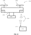
- FIG. 1 shows an example of a system used in visual navigation.
- the visual navigation system 100 may include a movable object 102 and a user terminal 106 capable of two-way communication with the movable object.
- the movable object may be configured to carry a payload 104.
- the user terminal can be used to control one or more motion characteristics of the movable object and/or the payload.
- the user terminal can be used to control the movable object such that the movable object is able to navigate in a specified direction 110 within the environment.
- the specified direction may be a target direction determined from a user input to the user terminal.
- One or more objects 108 may be located within the environment.
- the user terminal can be used to control the movable object such that the movable object is able to navigate towards, track, follow, or acquire data (e.g., image data) associated with the object.
- the movable object 102 may be any object capable of traversing an environment.
- the movable object may be capable of traversing air, water, land, and/or space.
- the environment may include stationary objects and objects that are capable of motion.
- stationary objects may include geographic features, plants, landmarks, buildings, monolithic structures, or any fixed structures.
- objects that are capable of motion may include people, vehicles, animals, projectiles, etc.
- the environment may be an inertial reference frame.
- the inertial reference frame may be used to describe time and space homogeneously, isotropically, and in a time-independent manner.
- the inertial reference frame may be established relative to the movable object, and move in accordance with the movable object. Measurements in the inertial reference frame can be converted to measurements in another reference frame (e.g., a global reference frame) by a transformation (e.g., Galilean transformation in Newtonian physics).
- a transformation e.g., Galilean transformation in Newtonian physics
- the movable object 102 may be a vehicle.
- the vehicle may be a self-propelled vehicle.
- the vehicle may traverse an environment with aid of one or more propulsion units.
- the vehicle may be an aerial vehicle, a land-based vehicle, a water-based vehicle, or a space-based vehicle.
- the vehicle may be an unmanned vehicle.
- the vehicle may be capable of traversing an environment without a human passenger onboard. Alternatively, the vehicle may carry a human passenger.
- the movable object may be an unmanned aerial vehicle (UAV).
- UAV unmanned aerial vehicle
- any description herein of a UAV or any other type of movable object may apply to any other type of movable object or various categories of movable objects in general, or vice versa.
- any description herein of a UAV may apply to any unmanned land-bound, water-based, or space-based vehicle. Further examples of movable objects are provided in greater detail elsewhere herein.
- the movable object may be capable of traversing within an environment.
- the movable object may be capable of flight within three dimensions.
- the movable object may be capable of spatial translation along one, two, or three axes.
- the one, two or three axes may be orthogonal to one another.
- the axes may be along a pitch, yaw, and/or roll axis.
- the movable object may also be capable of rotation about one, two, or three axes.
- the one, two, or three axes may be orthogonal to one another.
- the axes may be a pitch, yaw, and/or roll axis.
- the movable object may be capable of movement along up to 6 degrees of freedom.
- the movable object may include one or more propulsion units that may aid the movable object in movement.
- the movable object may be a UAV with one, two or more propulsion units.
- the propulsion units may be configured to generate lift for the UAV.
- the propulsion units may include rotors.
- the movable object may be a multi-rotor UAV.
- the movable object may have any physical configuration.
- the movable object may have a central body with one or arms or branches extending from the central body.
- the arms may extend laterally or radially from the central body.
- the arms may be movable relative to the central body or may be stationary relative to the central body.
- the arms may support one or more propulsion units.
- each arm may support one, two or more propulsion units.
- the movable object may have a housing.
- the housing may be formed from a single integral piece, two integral pieces, or multiple pieces.
- the housing may include a cavity within where one or more components are disposed.
- the components may be electrical components, such as a flight controller, one or more processors, one or more memory storage units, one or more sensors (e.g., one or more inertial sensors or any other type of sensor described elsewhere herein), one or more navigational units (e.g., a global positioning system (GPS) unit), one or communication units, or any other type of component.
- the housing may have a single cavity or multiple cavities.
- a flight controller may in communication with one or more propulsion units and/or may control operation of the one or more propulsion units.
- the flight controller may communicate and/or control operation of the one or more propulsion units with aid of one or more electronic speed control (ESC) modules.
- the flight controller may communicate with the ESC modules to control operation of the propulsion units.
- ESC electronic speed control
- the movable object may support an on-board payload 104.
- the payload may have a fixed position relative to the movable object, or may be movable relative to the movable object.
- the payload may spatially translate relative to the movable object. For instance, the payload may move along one, two or three axes relative to the movable object.
- the payload may also rotate relative to the movable object. For instance, the payload may rotate about one, two or three axes relative to the movable object.
- the axes may be orthogonal to on another.
- the axes may be a pitch, yaw, and/or roll axis.
- the payload may be fixed or integrated into the movable object.
- the payload may be movable relative to the movable object with aid of a carrier.
- the carrier may include one or more gimbal stages that may permit movement of the carrier relative to the movable object.
- the carrier may include a first gimbal stage that may permit rotation of the carrier relative to the movable object about a first axis, a second gimbal stage that may permit rotation of the carrier relative to the movable object about a second axis, and/or a third gimbal stage that may permit rotation of the carrier relative to the movable object about a third axis. Any descriptions and/or characteristics of carriers as described elsewhere herein may apply.
- the payload may include a device capable of sensing the environment about the movable object, a device capable of emitting a signal into the environment, and/or a device capable of interacting with the environment.
- One or more sensors may be provided as a payload, and may be capable of sensing the environment.
- the one or more sensors may include an imaging device.
- An imaging device may be a physical imaging device.
- An imaging device can be configured to detect electromagnetic radiation (e.g., visible, infrared, and/or ultraviolet light) and generate image data based on the detected electromagnetic radiation.
- An imaging device may include a charge-coupled device (CCD) sensor or a complementary metal-oxide-semiconductor (CMOS) sensor that generates electrical signals in response to wavelengths of light.
- CMOS complementary metal-oxide-semiconductor
- the resultant electrical signals can be processed to produce image data.
- the image data generated by an imaging device can include one or more images, which may be static images (e.g., photographs), dynamic images (e.g., video), or suitable combinations thereof.
- the image data can be polychromatic (e.g., RGB, CMYK, HSV) or monochromatic (e.g., grayscale, black-and-white, sepia).
- the imaging device may include a lens configured to direct light onto an image sensor.
- the imaging device can be a camera.
- a camera can be a movie or video camera that captures dynamic image data (e.g., video).
- a camera can be a still camera that captures static images (e.g., photographs).
- a camera may capture both dynamic image data and static images.
- a camera may switch between capturing dynamic image data and static images.
- a camera can be used to generate 2D images of a 3D scene (e.g., an environment, one or more objects, etc.).
- the images generated by the camera can represent the projection of the 3D scene onto a 2D image plane. Accordingly, each point in the 2D image corresponds to a 3D spatial coordinate in the scene.
- the camera may comprise optical elements (e.g., lens, mirrors, filters, etc).
- the camera may capture color images, greyscale image, infrared images, and the like.
- the camera may be a thermal imaging device when it is configured to capture infrared images.
- the payload may include multiple imaging devices, or an imaging device with multiple lenses and/or image sensors.
- the payload may be capable of taking multiple images substantially simultaneously.
- the multiple images may aid in the creation of a 3D scene, a 3D virtual environment, a 3D map, or a 3D model.
- a right image and a left image may be taken and used for stereo-mapping.
- a depth map may be calculated from a calibrated binocular image. Any number of images (e.g., 2 or more, 3 or more, 4 or more, 5 or more, 6 or more, 7 or more, 8 or more, 9 or more) may be taken simultaneously to aid in the creation of a 3D scene/virtual environment/model, and/or for depth mapping.
- the images may be directed in substantially the same direction or may be directed in slightly different directions.
- data from other sensors e.g., ultrasonic data, LIDAR data, data from any other sensors as described elsewhere herein, or data from external devices
- ultrasonic data e.g., ultrasonic data, LIDAR data, data from any other sensors as described elsewhere herein, or data from external devices
- LIDAR data e.g., ultrasonic data, LIDAR data, data from any other sensors as described elsewhere herein, or data from external devices
- the imaging device may capture an image or a sequence of images at a specific image resolution.
- the image resolution may be defined by the number of pixels in an image.
- the image resolution may be greater than or equal to about 352x420 pixels, 480x320 pixels, 720x480 pixels, 1280x720 pixels, 1440 ⁇ 1080 pixels, 1920 ⁇ 1080 pixels, 2048x1080 pixels, 3840x2160 pixels, 4096x2160 pixels, 7680x4320 pixels, or 15360x8640 pixels.
- the camera may be a 4K camera or a camera with a higher resolution.
- the imaging device may capture a sequence of images at a specific capture rate.
- the sequence of images may be captured standard video frame rates such as about 24p, 25p, 30p, 48p, 50p, 60p, 72p, 90p, 100p, 120p, 300p, 50i, or 60i.
- the sequence of images may be captured at a rate less than or equal to about one image every 0.0001 seconds, 0.0002 seconds, 0.0005 seconds, 0.001 seconds, 0.002 seconds, 0.005 seconds, 0.01 seconds, 0.02 seconds, 0.05 seconds. 0.1 seconds, 0.2 seconds, 0.5 seconds, 1 second, 2 seconds, 5 seconds, or 10 seconds.
- the capture rate may change depending on user input and/or external conditions (e.g. rain, snow, wind, unobvious surface texture of environment).
- the imaging device may have adjustable parameters. Under differing parameters, different images may be captured by the imaging device while subject to identical external conditions (e.g., location, lighting).
- the adjustable parameter may comprise exposure (e.g., exposure time, shutter speed, aperture, film speed), gain, gamma, area of interest, binning/subsampling, pixel clock, offset, triggering, ISO, etc.
- Exposure e.g., exposure time, shutter speed, aperture, film speed
- gain e.g., gamma, area of interest, binning/subsampling, pixel clock, offset, triggering, ISO, etc.
- Parameters related to exposure may control the amount of light that reaches an image sensor in the imaging device.
- shutter speed may control the amount of time light reaches an image sensor and aperture may control the amount of light that reaches the image sensor in a given time.
- Parameters related to gain may control the amplification of a signal from the optical sensor.
- ISO may control the level of sensitivity of the camera to
- an imaging device may extend beyond a physical imaging device.
- an imaging device may include any technique that is capable of capturing and/or generating images or video frames.
- the imaging device may refer to an algorithm that is capable of processing images obtained from another physical device.
- a payload may include one or more types of sensors.
- types of sensors may include location sensors (e.g., global positioning system (GPS) sensors, mobile device transmitters enabling location triangulation), vision sensors (e.g., imaging devices capable of detecting visible, infrared, or ultraviolet light, such as cameras), proximity or range sensors (e.g., ultrasonic sensors, lidar, time-of-flight or depth cameras), inertial sensors (e.g., accelerometers, gyroscopes, and/or gravity detection sensors, which may form inertial measurement units (IMUs)), altitude sensors, attitude sensors (e.g., compasses), pressure sensors (e.g., barometers), temperature sensors, humidity sensors, vibration sensors, audio sensors (e.g., microphones), and/or field sensors (e.g., magnetometers, electromagnetic sensors, radio sensors).
- location sensors e.g., global positioning system (GPS) sensors, mobile device transmitters enabling location triangulation
- vision sensors e.g.
- the payload may include one or more devices capable of emitting a signal into an environment.
- the payload may include an emitter along an electromagnetic spectrum (e.g., visible light emitter, ultraviolet emitter, infrared emitter).
- the payload may include a laser or any other type of electromagnetic emitter.
- the payload may emit one or more vibrations, such as ultrasonic signals.
- the payload may emit audible sounds (e.g., from a speaker).
- the payload may emit wireless signals, such as radio signals or other types of signals.
- the payload may be capable of interacting with the environment.
- the payload may include a robotic arm.
- the payload may include an item for delivery, such as a liquid, gas, and/or solid component.
- the payload may include pesticides, water, fertilizer, fire-repellant materials, food, packages, or any other item.
- payloads may apply to devices that may be carried by the movable object or that may be part of the movable object.
- one or more sensors may be part of the movable object.
- the one or more sensors may or may be provided in addition to the payload. This may apply for any type of payload, such as those described herein.
- the movable object may be capable of communicating with the user terminal 106.
- the user terminal may communicate with the movable object itself, with a payload of the movable object, and/or with a carrier of the movable object, wherein the carrier is used to support the payload.
- Any description herein of communications with the movable object may also apply to communications with the payload of the movable object, the carrier of the movable object, and/or one or more individual components of the movable object (e.g., communication unit, navigation unit, propulsion units, power source, processors, memory storage units, and/or actuators).
- the communications between the movable object and the user terminal may be wireless communications.
- Direct communications may be provided between the movable object and the user terminal.
- the direct communications may occur without requiring any intermediary device or network.
- Indirect communications may be provided between the movable object and the user terminal.
- the indirect communications may occur with aid of one or more intermediary device or network.
- indirect communications may utilize a telecommunications network.
- Indirect communications may be performed with aid of one or more router, communication tower, satellite, or any other intermediary device or network.
- Examples of types of communications may include, but are not limited to: communications via the Internet, Local Area Networks (LANs), Wide Area Networks (WANs), Bluetooth, Near Field Communication (NFC) technologies, networks based on mobile data protocols such as General Packet Radio Services (GPRS), GSM, Enhanced Data GSM Environment (EDGE), 3G, 4G, or Long Term Evolution (LTE) protocols, Infra-Red (IR) communication technologies, and/or Wi-Fi, and may be wireless, wired, or a combination thereof.
- LANs Local Area Networks
- WANs Wide Area Networks
- NFC Near Field Communication
- GPRS General Packet Radio Services
- GSM Global System for Mobile communications
- EDGE Enhanced Data GSM Environment
- 3G Third Generation
- 4G Long Term Evolution
- LTE Long Term Evolution
- IR Infra-Red
- Wi-Fi Wi-Fi
- the user terminal may be any type of external device.
- Examples of user terminals may include, but are not limited to, smartphones/cellphones, tablets, personal digital assistants (PDAs), laptop computers, desktop computers, media content players, video gaming station/system, virtual reality systems, augmented reality systems, wearable devices (e.g., watches, glasses, gloves, headgear (such as hats, helmets, virtual reality headsets, augmented reality headsets, head-mounted devices (HMD), headbands), pendants, armbands, leg bands, shoes, vests), gesture-recognition devices, microphones, any electronic device capable of providing or rendering image data, or any other type of device.
- the user terminal may be a handheld object.
- the user terminal may be portable.
- the user terminal may be carried by a human user. In some cases, the user terminal may be located remotely from a human user, and the user can control the user terminal using wireless and/or wired communications.
- Various examples, and/or characteristics of user terminals are provided in greater detail elsewhere here
- the user terminals may include one or more processors that may be capable of executing non-transitory computer readable media that may provide instructions for one or more actions.
- the user terminals may include one or more memory storage devices comprising non-transitory computer readable media including code, logic, or instructions for performing the one or more actions.
- the user terminal may include software applications that allow the user terminal to communicate with and receive imaging data from a movable object.
- the user terminals may include a communication unit, which may permit the communications with the movable object.
- the communication unit may include a single communication module, or multiple communication modules.
- the user terminal may be capable of interacting with the movable object using a single communication link or multiple different types of communication links.
- the user terminal may include a display.
- the display may be a screen.
- the display may or may not be a touchscreen.
- the display may be a light-emitting diode (LED) screen, OLED screen, liquid crystal display (LCD) screen, plasma screen, or any other type of screen.
- the display may be configured to show a graphical user interface (GUI).
- the GUI may show an image that may permit a user to control actions of the UAV. For instance, the user may select a direction of travel for the movable object from the image.
- the user may select a portion of the image (e.g., point, region, and/or object) to define the target direction.
- the user may select the target direction by directly touching the screen (e.g., touchscreen).
- the user may touch a portion of the screen, for example by touching a point on the screen.
- the user may select a region on a screen from a pre-existing set of regions, or may draw a boundary for a region, a diameter of a region, or specify a portion of the screen in any other way.
- the user may select the target direction by selecting the portion of the image with aid of a user interactive device (e.g., mouse, joystick, keyboard, trackball, touchpad, button, verbal commands, gesture-recognition, attitude sensor, thermal sensor, touch-capacitive sensors, or any other device).
- a touchscreen may be configured to detect location of the user's touch, length of touch, pressure of touch, and/or touch motion, whereby each of the aforementioned manner of touch may be indicative of a specific input command from the user.
- the image on the display may show a view collected with aid of a payload of the movable object.
- an image captured by the imaging device may be shown on the display.
- This may be considered a first person view (FPV).
- FPV first person view
- a single imaging device may be provided and a single FPV may be provided.
- multiple imaging devices having different fields of view may be provided.
- the views may be toggled between the multiple FPVs, or the multiple FPVs may be shown simultaneously.
- the multiple FPVs may correspond to (or generated by) different imaging devices, which may have different field of views.
- a user at a user terminal may select a portion of the image collected by the imaging device to specify a target and/or direction of motion by the movable object.
- the image on the display may show a map that may be generated with aid of information from a payload of the movable object.
- the map may optionally be generated with aid of multiple imaging devices (e.g., right camera, left camera, or more cameras), which may utilize stereo-mapping techniques.
- the map may be generated based on positional information about the movable object relative to the environment, the imaging device relative to the environment, and/or the movable object relative to the imaging device.
- Positional information may include posture information, spatial location information, angular velocity, linear velocity, angular acceleration, and/or linear acceleration.
- the map may be optionally generated with aid of one or more additional sensors, as described in greater detail elsewhere herein.
- the map may be a two-dimensional (2D) map or a three-dimensional (3D) map.
- the views may be toggled between a two-dimensional and a three-dimensional map view, or the two-dimensional and three-dimensional map views may be shown simultaneously.
- a user at a user terminal may select a portion of the map to specify a target and/or direction of motion by the movable object.
- the views may be toggled between one or more FPV and one or more map view, or the one or more FPV and one or more map view may be shown simultaneously.
- the user may make a selection of a target or direction using any of the views.
- the portion selected by the user may include the target and/or direction.
- the user may select the portion using any of the selection techniques as described.
- the image may be provided in a 3D virtual environment that is displayed on the user terminal (e.g., virtual reality system or augmented reality system).
- the 3D virtual environment may optionally correspond to a 3D map.
- the virtual environment may comprise a plurality of points or objects that can be manipulated by a user.
- the user can manipulate the points or objects through a variety of different actions in the virtual environment. Examples of those actions may include selecting one or more points or objects, drag-and-drop, translate, rotate, spin, push, pull, zoom-in, zoom-out, etc. Any type of movement action of the points or objects in a three-dimensional virtual space may be contemplated.
- a user at a user terminal can manipulate the points or objects in the virtual environment to control a motion path of the movable object and/or motion characteristic(s) of the movable object.
- the user terminal may optionally be used to control the movement of the movable object, such as the flight of the movable object.
- the user terminal may permit a user to manually directly control flight of the movable object.
- a separate device may be provided that may allow a user to manually directly control flight of the movable object.
- the separate device may or may not be in communication with the user terminal.
- the flight of the movable object may optionally be fully autonomous or semi-autonomous.
- the user terminal may optionally be used to control any component of the movable object (e.g., operation of the payload, operation of the carrier, one or more sensors, communications, navigation, landing stand, actuation of one or more components, power supply control, or any other function).
- a separate device may be used to control one or more components of the movable object.
- the separate device may or may not be in communication with the user terminal.
- One or more components may be controlled automatically with aid of one or more processors.
- the target direction 110 may be selected by a user.
- the movable object may travel in the target direction.
- the target direction may be selected by a user selecting a portion of an image (e.g., in FPV or map view).
- the movable object may travel in the target direction until a countermanding instruction is received or when a countermanding condition is realized. For instance, the movable object may automatically travel in the target direction until a new direction is input.
- the movable object may travel in the target direction until a different flight mode is selected. For instance, the user may take manual control over the flight of the movable object.
- Restrictions may be provided for the travel of the movable object.
- a condition may be detected in which a flight restriction may apply.
- obstacle avoidance may occur when undergoing target or direction tracking. Additional limitations such as flight ceilings, flight floors, limited range, or other types of flight restrictions may apply.
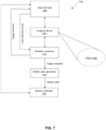
- FIG. 2 shows an example of communications that may occur within a visual navigation system.
- a user terminal 206 may be provided and configured to accept an input from one or more users.
- the user terminal may be in communication with a movable object.
- the user terminal may be in communication with an imaging device 204 and a motion controller 218 onboard the movable object.
- the visual navigation system may further include a direction analyzer 212 in communication with the user terminal, the imaging device, and the motion controller.
- the direction analyzer may or may not be part of the motion controller.
- the direction analyzer can be configured to determine a target direction for the movable object, based on a user input to the user terminal and one or more images obtained by the imaging device.
- the imaging device can capture images which may include portions indicative of one or more objects 208 and/or one or more direction(s) 210.
- the user terminal may include an output device.
- the output device may be a display, such as a screen.
- the screen can also serve as an input device.
- a user may interact with the user terminal via the screen.
- a user can manipulate visual objects in a graphical user interface (GUI) on the touchscreen by selecting (clicking or touching) the visual objects through a variety of actions. Examples of those actions may include selecting one or more points or objects, draw a shape, drag-and-drop, translate, rotate, spin, push, pull, zoom-in, zoom-out, etc. Any type of user action in the GUI may be contemplated.
- a user at a user terminal can manipulate the visual objects in the GUI to control a direction, motion path, tracking function, and/or motion characteristic(s) of the movable object.
- the display may have any characteristics as described elsewhere herein.
- the display may be incorporated into the user terminal or may be provided separately from the rest of the user terminal. When provided separately from the rest of the user terminal, the display may communicate with the user terminal. Two-way communications may optionally be provided between the output device and the rest of the user terminal.
- the user terminal may be configured to display, on the output device, one or more images through which a user can select a target direction.
- the images may include FPVs and/or map views.
- the image may include a live-image or visual representation of a target direction after the target direction has been selected.
- the target direction may be determined when a user makes a selection in the image. For example, a portion of an image selected by the user may constitute a target direction.
- One or more imaging devices 204 may be provided.
- the one or more imaging devices may have substantially the same field of view or different fields of view.
- One or more imaging devices may be movable relative to the movable object, while one or more imaging devices may be stationary relative to the movable object.
- one or more of the imaging devices may be supported by a carrier that may permit movement of the imaging device relative to the movable object.
- One or more of the imaging devices may be directly on the movable object, move in the same direction and speed as the movable object, and/or may not move relative to the movable object.
- One or more imaging devices may capture images of an environment.
- the environment may include one or more objects 208.
- the directions 210 can be defined or determined when the user makes a selection within the image.
- the target directions may be defined or determined from images of the one or more objects.
- the image data captured by the one or more imaging devices may correspond to, for example, still images or video frames of the one or more objects.
- the objects may include any physical object or structure that can be optically imaged by the movable object.
- the objects can be depicted in still images and/or video frames in a 2D or 3D format, can be real-life and/or animated, can be in color, black/white, or grayscale, can be in any color space, or can be in a wireframe model.
- Images from the one or more imaging devices may be transmitted from the imaging devices to the user terminal, to be rendered on an output device of the user terminal.
- Image data can be transmitted from the imaging device to the direction analyzer 212.
- the direction analyzer can be on-board the imaging device, on-board a carrier, on-board the movable object, or an external device (e.g., user terminal, server, etc.).
- the direction analyzer may be located remotely from the imaging device.
- the direction analyzer may be disposed in a remote server that is in communication with the imaging device.
- the direction analyzer may be provided at any other type of external device (e.g., a remote controller for the movable object, a base station having a reference location, etc.), or may be distributed on a cloud computing infrastructure.
- the direction analyzer and the motion controller may be located on a same device.
- the direction analyzer and the motion controller may be located on different devices.
- the direction analyzer and the motion controller may communicate either via wired or wireless communication channels.
- the direction analyzer may be located on the movable object.
- the direction analyzer may be disposed in a housing of the movable object.
- the direction analyzer may be disposed at a base station that is in communication with the movable object.
- the direction analyzer may be located anywhere, as long as the direction analyzer is capable of: (i) receiving image data from the imaging device, (ii) receiving an input from the user terminal, whereby the input is used to determine a target direction, (iii) analyzing the input with reference to the image data to determine the target direction in both a camera coordinate system and a world coordinate system, and (iv) transmitting the target direction to the motion controller and the user terminal.
- the user terminal may be configured to display the target direction as a graphical element on the rendered image.
- the motion controller may be configured to effect movement of the movable object based on the target direction.
- the image data captured by the imaging device may be stored in a media storage (not shown) before the image data is provided to the direction analyzer.
- the direction analyzer may be configured to receive the image data directly from the media storage.
- the direction analyzer may be configured to receive image data concurrently from both the imaging device and the media storage.
- the media storage can be any type of storage medium capable of storing image data of a plurality of objects.
- the image data may include video or still images. The video or still images may be processed and analyzed by the direction analyzer, as described later in the specification.
- the media storage can be provided as a CD, DVD, Blu-ray disc, hard disk, magnetic tape, flash memory card/drive, solid state drive, volatile or non-volatile memory, holographic data storage, and any other type of storage medium.
- the media storage can be a computer capable of providing image data to the direction analyzer.
- the media storage can be a web server, an enterprise server, or any other type of computer server.
- the media storage can be computer programmed to accept requests (e.g., HTTP, or other protocols that can initiate data transmission) from the direction analyzer and to serve the direction analyzer with requested image data.
- requests e.g., HTTP, or other protocols that can initiate data transmission
- the media storage can be a broadcasting facility, such as free-to-air, cable, satellite, and other broadcasting facility, for distributing image data.
- the media storage may also be a server in a data network (e.g., a cloud computing network).
- the media storage may be located on-board the imaging device. In some other embodiments, the media storage may be located on-board the movable object but off-board the imaging device. In some further embodiments, the media storage may be located on one or more external devices off-board the movable object and/or the imaging device. In those further embodiments, the media storage may be located on a remote controller, a ground station, a server, etc. Any arrange or combination of the above components may be contemplated. In some embodiments, the media storage may communicate with the imaging device via a peer-to-peer network architecture. In some embodiments, the media storage may be implemented using a cloud computing architecture.
- the image data may be provided (e.g., in the form of image signals) to the direction analyzer for processing/analysis to determine a target direction.
- the direction analyzer can be implemented as a software program executing in a processor and/or as hardware that analyzes one or more image frames to determine a target direction.
- the direction analyzer may be further configured to determine the relative positions between the movable object and the target direction.
- the direction analyzer may determine a position of the imaging device and/or movable object with respect to the environment (e.g., an inertial reference frame) and/or one another.
- the direction analyzer may determine a vector of the target direction within the environment (e.g., an inertial reference frame) and/or with respect to the movable object (which may include an imaging device supported by the movable object).
- data from one or more additional sensors and/or external devices may be used to aid in determination of positional information by the direction analyzer (for example, IMU data or data from any other sensors as described elsewhere herein).
- positional information may include spatial location (e.g., in reference to one, two or three axes), attitude (e.g., relative to one, two or three axes), linear velocity, angular velocity, linear acceleration, and/or angular acceleration.
- Image frames from the imaging device may be displayed on the output device of the user terminal.
- a map may be displayed that is indicative of the environment and/or positions of various objects and/or the movable object within the environment.
- the map may be a 2D map or a 3D map.
- the map may be displayed on the output device.
- Data from the direction analyzer may be provided directly to the user terminal which may display it on its output device without requiring any intermediary analysis or processing.
- data indicative of the target direction may be transmitted from the direction analyzer, to be displayed on the output device of the user terminal.
- the data from the direction analyzer may be provided to the motion controller.
- the motion controller may be provided on-board the movable object, on-board the carrier, on-board the imaging device, and/or on an external device or network.
- the motion controller may control flight of the movable object.
- the motion controller may generate one or more flight instructions to be provided to one or more propulsion units of the movable object.
- the motion controller may optionally generate a motion path for the movable object.
- the motion path may be substantially fixed, or may be variable or dynamic.
- the motion path may include a heading in a target direction.
- the motion path may remain heading in the target direction until a countermanding condition is detected (e.g., a further input is detected or a flight restriction applies).
- the motion controller may be in communication with one or more propulsion units of the movable object (not pictured).
- information from one or more sensors may be provided to the motion controller.
- information from one or more sets of IMUs may be provided to the motion controller.
- the one or more sets of IMUs may be on-board the movable object, on-board a carrier and/or on-board a payload.
- the data from the IMUs may be indicative of positional information of the movable object, the carrier, and/or the payload.
- the motion controller may optionally use the information from the one or more sensors in controlling motion of the movable object.
- the information from the one or more sensors may be used to control position of the imaging device relative to the movable object and/or its environment.
- the motion controller may receive information from the user terminal.
- the motion controller may receive information indicative of the user selection of a target direction.
- the motion controller may generate a motion path and/or control motion of the movable object in response to the user selection of the target direction.
- Information from the motion controller may optionally be provided to the user terminal.
- a user terminal may receive information about a motion path.
- the motion path and/or heading may optionally be displayed on the output device.
- FIG. 2 While shown in FIG. 2 as separate components that are operatively connected, it is understood that the as-shown configuration is for illustrative purposes only. Certain components or devices may be removed or combined, and other components or devices may be added.
- a method for determining a target direction for a movable object can be implemented using the system of FIG. 2 .
- the method may include providing an image on a computer-implemented display, obtaining a position of a selected point on the image when a user selects the point on the image, and determining the target direction based on the position of the selected point on the image.
- the target direction may be generated using, for example direction analyzer 212.
- the image can be captured by an imaging device (e.g., imaging device 204) onboard a movable object.
- the image may visually depict a portion of an environment within which the movable object moves.
- the image may depict a first-person view (FPV) taken from the movable object.
- the image may be an environmental map of the environment.
- the environmental map may be a topological map.
- the environmental map may also comprise a metric map.
- the metric map may comprise at least one of the following: a point cloud, a 3D grid map, a 2D grid map, or a 2.5D grid map. In some instances, the metric map may comprise an occupancy grid map.
- the image data may be transmitted directly or indirectly from the imaging device and/or the movable object to a user terminal (e.g., user terminal 206).
- the computer-implemented display may be a touchscreen device in the user terminal.
- the image may be rendered substantially in or near real-time on the computer-implemented display.
- a user can control the movable object to move in a target direction, by selecting a point or a portion of the image associated with the target direction, as described in detail below.
- one or more coordinate systems may be local to an imaging device, and/or the movable object.
- One or more coordinate systems may include global coordinate systems that are provided relative to an inertial reference frame, such as the environment.
- a position of the imaging device and/or movable object can be determined in reference to a global coordinate system.
- the position of the imaging device and/or movable object can be determined in reference to a local coordinate.
- the position of the imaging device and/or movable object may be converted between global and local coordinates.
- a target direction in an image may be determined in relation to a local coordinate system of the imaging device and/or the image captured by the imaging device.
- the local coordinates of the target direction can be converted to global coordinates for the target direction.
- a vector in a local coordinate system denoting the target direction can be converted to a vector in the global coordinate systems.
- the local coordinate system may be a camera coordinate system of the imaging device.
- the global coordinate system may be a world coordinate system of the environment within which the movable object moves.
- a method for calculating/converting a user's selected point on a display screen to a target direction in a space within which the movable object moves is described as follows.
- a position of a selected point on the image may be obtained when a user selects the point on the image.
- the display screen is a touchscreen
- the user may select the point by touching, tapping, or clicking a portion of the touchscreen.
- the position of the selected point on the image may be obtained by converting a set of screen coordinates of the selected point into a set of image coordinates, and normalizing the set of image coordinates.
- the target direction may be determined based on the normalized set of image coordinates.
- coordinates (x screen , y screen ) of the selected point corresponding to a screen position can be obtained.
- the coordinates (x screen , y screen ) of the selected point can be obtained via an application programming interface (API).
- the API may be, for example an IOS TM -based API or Android TM -based API implemented on the user terminal.
- the coordinates (x screen ,y screen ) of the selected point can be converted into coordinates (x rawimage ,y rawimage ) which are the coordinates of the selected point in the raw image captured by the imaging device.
- the raw image coordinates (x rawimage ,y rawimage ) of the selected point can be normalized to (x percentage , y percentage ), based on a position and a percentage of the current preview image within the raw image .
- the above conversion and/or normalization can be performed by the user terminal using a combination of software and/or hardware.
- the normalized coordinates (x percentage , y percentage ) of the user selected point 220 may be transmitted from the user terminal to the direction analyzer via one or more communication channels.
- the direction analyzer can be configured to calculate a spatial target direction (x space , y space , z space ) based on the normalized coordinates (x percentage , y percentage ).
- the direction analyzer can be further configured to transmit the target direction (x space , y space , z space ) to the user terminal and the motion controller.
- the target direction may be converted into 2-D display coordinates (x dir , y dir ), which are then projected and displayed onto the image rendered on the user terminal.
- the motion controller can be configured to control movement of the movable object based on the target direction (x space , y space , z space ).
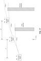
- FIG. 3 shows a geometry model of camera imaging.
- the geometry model may assume that an optical axis of the camera aligns with a center of the captured image, although the invention is not limited thereto. In some other geometry models, the optical axis need not be aligned with the center of the captured image, and can be offset from the center of the image.
- the point (x w ,y w ,z w ) is an arbitrary point in a world coordinate system defined with respect to a point O
- D is a depth of the point in the world coordinate system
- z w D
- (x i ,y i ) are the corresponding coordinates of the same point (x w ,y w ,z w ) in a camera coordinate system.
- the coordinates (x w , y w , z w ) contains an unknown value D.
- a normalization step can be performed to eliminate the unknown value D since the selected direction is a direction vector.
- the vector OA of the target direction in the camera coordinate system can be obtained based on a point (x w , y w , z w ) in a world coordinate system.
- the point (x w , y w , z w ) in the world coordinate system may be associated with the selected point (x i , y i ) in the camera coordinate system.
- the point (x w , y w , z w ) in the world coordinate system may comprise a depth value D.
- the vector OA of the target direction in the camera coordinate system can be obtained by normalizing (x w , y w , z w ) with respect to the depth value D, and the depth value D can be eliminated from the vector OA after the normalization.
- the vector OA of the target direction in the camera coordinate system can be converted into a vector OA gnd of the target direction in the world coordinate system using a translation matrix.
- the translation matrix can be obtained by using data collected from one or more sensors on the movable object.
- the one or more sensors may be located on an IMU of the movable object.
- the one or more sensors may be configured to measure an attitude of the movable object.
- the translation matrix can be obtained using in part the attitude of the movable object.
- the direction analyzer may be configured to transmit the calculated target direction back to the user terminal.
- the user terminal may be configured to re-project the target direction as a graphical element onto the image in the computer-implemented display.
- the process of re-projecting the direction vector OA onto the preview image is a reverse of the method described in FIG. 3 .
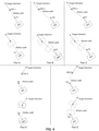
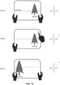
- FIG. 4 shows an example of a user interface (UI) through which a user can select a target direction, in accordance with some embodiments.
- Part A shows an initial display of an environment.
- Part B shows a user selecting a target direction within the initial display.
- Part C shows an image of the movable object traveling in the target direction.
- the movable object may be a UAV. Corresponding movements/headings of the UAV are shown in the compasses.
- Part A shows an initial display of an environment.
- a FPV may be provided as illustrated.
- the FPV may include a live streaming image from an imaging device.
- the FPV may alternatively be a graphical depiction or representation of the image from the imaging device.
- a horizon is shown, along with an object within the field of view.
- the UAV may be stationary or moving while the initial display of the environment is occurring.
- the corresponding compass shows a stationary UAV.
- a map view may be provided.
- the map view may include a 2D map, such as an overhead map.
- the map view may include a 3D map.
- the 3D map may be alterable to view the 3D environment from various angles. Solid renderings, wireframes, or other types of imaging may be shown, as described previously herein.
- the display may be shown on a user terminal. A user may optionally hold the user terminal.
- Part B shows a user selecting a target direction within the initial display.
- the user may select a portion of the image to select the target direction.
- the image may include a FPV and/or a map.
- the user may select a portion of the FPV or the map to select the target direction.
- the portion of the image selected by the user may optionally be a point.
- the UAV may travel in the direction indicated by the selected point.
- a directional heading of the UAV may be determined by a current location of the UAV and an angle that includes the selected point along the trajectory.
- the user may select a target direction that is northeast of the current position of the UAV.
- the corresponding compass shows the UAV may move in a corresponding northeastern direction.
- the user selection of a target direction may include a lateral selection of the target direction.
- the target direction may be within a two-dimensional plane.
- the user may specify whether the UAV is to move north, south, east, west, or anywhere in between.
- the UAV may remain at substantially the same altitude while traveling in the specified two-dimensional direction.
- the UAV may encounter flight restrictions that may affect the flight path of the UAV. For instance, some lateral flight restrictions may apply.
- the UAV may remain within a certain range of the user terminal. If the UAV is traveling in a target direction, and is about to exceed the range of the user terminal, the UAV may stop and hover, or may return toward the user terminal.
- the UAV may remain within a geo-fenced region. If the UAV is traveling in a target direction, and is about to pass outside of the geo-fenced region, the UAV may stop hover, or may return toward the user terminal.
- An obstacle may be a flight restricted area. Alternatively a flight restricted area may or may not contain any obstacle. Any other type of flight restriction may apply.
- the user selection of a target direction may include a three-dimensional selection of the target direction.
- the target direction may be anywhere within a three-dimensional space.
- the user may specify whether the UAV is to move north, south, east, west, up, or down, or anywhere in between.
- the UAV may be capable of changing altitude while traveling within the specified three-dimensional direction.
- the UAV may encounter flight restrictions that may affect the flight path of the UAV. Lateral flight restrictions, such as those previously described, may be provided. Additional altitude flight restrictions may be provided that may limit altitude change of the UAV. For instance, if the target direction is upwards, the UAV may travel in that target direction indefinitely, all the while increasing the altitude of the UAV. Alternatively, the flight restriction, such as a flight ceiling, may kick in. When the UAV reaches the flight ceiling, the UAV may level out and remain at substantially the same altitude. However, the UAV may continue to travel in the same specified lateral direction. Similarly, if the target direction is downwards, the UAV may travel in that direction indefinitely until it reaches the ground, all the while decreasing the altitude. Alternatively, the flight restriction, such as a flight floor, may kick in. When the UAV reaches the flight floor, the UAV may level out and remain at substantially the same altitude. However, the UAV may continue to travel in the same specified lateral direction.
- visual indicators such as compass and/or vector
- heading information indicative of flight angles, compass direction, future/target destination, etc. may optionally be displayed on a 2D map and/or a 3D map.
- the precision to which the user may specify a direction may be on the order of 0.01 degrees or less, 0.05 degrees or less, 0.1 degrees or less, 0.5 degrees or less, 1 degree or less 2 degrees or less, 3 degrees or less, 5 degrees or less, 7 degrees or less, 10 degrees or less, 15 degrees or less, 20 degrees or less, or 30 degrees or less.
- the selected target direction may or may not be visually indicated on the screen.
- a visual marker may be provided within the image indicative of the target direction.
- the visual marker may be a point, region, icon, line, or vector.
- the point may be indicative of a selection of the target direction.
- the vector may be indicative of the direction that the UAV is heading.
- a user may specify that the UAV is in a directional mode.
- the portion of the image selected by the user may determine the direction at which the UAV will travel until it encounters other directions, or encounters flight restrictions.
- the UAV may travel indefinitely in that direction until it encounters a stop or change criteria, such as a direction change, flight restriction, flight mode change, low power supply or obstacle.
- the user may specify that the UAV is in a directional mode by selecting the directional mode from one or more available modes, such as a target tracking mode.
- the UAV may fly in a target direction when a user selects a user-interface tool that indicates that the portion of the image that the user will select will be the target direction.
- the target direction tool may be a one-use tool (e.g., the user may need to reselect the tool in order to select another target direction), or may be used multiple times (the user can keep specifying target direction without having to re-select the tool unless the user has switched tools).
- one or more images (e.g., FPV, 2D map and/or 3D map) on the screen may have one or more predetermined regions indicative of flight direction.
- the regions may be visually distinguishable from other regions.
- the regions may include borders, or arrows, or any other type of features that may distinguish the region.
- the regions may be provided in a border surrounding the image.
- one or more arrow buttons may be provided that may allow the target direction of the UAV to be adjusted.
- a user may indicate one or more values or coordinates indicative of the target direction that the UAV is to travel.
- angles may provide a target direction for the UAV to head. The angles may be provided for two dimensional or three dimensional direction control.
- the values may include spatial coordinates which are along a vector descriptive of the target direction.
- Any other user interface tools or techniques may be provided that allow a user to specify a target direction using the user interface.
- Part C shows an image captured by the UAV when it is traveling in the target direction. For instance, from a FPV, when a UAV is traveling in the specified direction, an object that was once further away may become closer up. From a map view, objects may be shown to be passed by the UAV as the UAV follows the target direction. As shown on the corresponding compass, the UAV may be continuing to travel in the target direction.
- the UAV when a user specifies a target direction, the UAV may travel in that target direction at a fixed velocity or a variable velocity.
- a standard target travel velocity may be provided.
- a variable target travel velocity may also be provided.
- the user may specify the velocity and/or acceleration at which the UAV may be traveling in the target direction. Any description herein of affecting the velocity of the UAV may also apply to affecting acceleration of the UAV in the target direction.
- the user may affect the velocity at the same time at which the user is specifying the target direction. For instance, when a user selects a target direction, the number of clicks or touches that a user touches the target direction may affect the velocity of the UAV.
- the UAV may travel at a first velocity
- the UAV may travel a second velocity.
- the second velocity may be greater than the first velocity.
- the velocity of the UAV travel may correspond to the number of touches or selections of the point indicative of the target direction.
- a positive proportional relationship may be provided between the number of selections and the velocity of the UAV.
- a linear relationship may be provided between the number of selections and the velocity of the UAV.
- the velocity of the UAV may be X + N ⁇ Y, where X is a velocity value, Y is a velocity multiplier, and N is the number of times the target direction was selected. Any other mathematical relation may be provided.
- the user may make a selection a first time to get a first velocity, and then make the selection again to speed up the UAV. The user may keep making the selection to keep speeding up the UAV.
- the length of the selection of the target direction may affect the velocity of the UAV. For instance, if a user touches a point indicative of a target direction for a first period of time, the UAV may travel at a first velocity, and if the user touches a second period of time greater than the first period of time, the UAV may travel a second velocity. The second velocity may be greater than the first velocity. The velocity of the UAV travel may correspond to the length of the touch or selection of the point indicative of the target direction. A positive proportional relationship may be provided between the length of the selection and the velocity of the UAV. In some instances, a linear relationship may be provided between the length of the selection and the velocity of the UAV.
- swiping motions may affect the velocity of the UAV.
- different regions may be touched to affect the velocity of the UAV.
- a separate control may be provided for velocity control. For instance, a user may adjust a velocity using a manual control while the UAV is traveling in the target direction. The velocity may be adjusted in accordance with the manual control in real-time.
- a user may enter a numerical value for the desired velocity, or select the velocity from a plurality of pre-selected options.
- FIG. 5 shows an example of a user interface (UI) through which a user can adjust a target direction, in accordance with some embodiments.
- Part A shows a display of an environment while a UAV is heading in a first target direction.
- Part B shows a user selecting a second target direction different from the first target direction within the display.
- Part C shows an image captured by the UAV when it is traveling in the second target direction.
- the image is illustrated as a FPV, but may also be a map in conjunction with or as an alternative to the FPV. Corresponding movements/headings of the UAV are shown in the compasses.
- Part A shows a display of an environment while a UAV is heading in a first target direction.
- the corresponding compass shows that the UAV is traveling in a northeast direction.
- the UAV may continue along that target direction until it encounters a situation that requires a change in direction, such as those previously described (e.g., a direction change, flight restriction, flight mode change, low power supply or obstacle).
- the UAV may continue in the target direction along a constant velocity and/or acceleration or a varying velocity and/or acceleration.
- Part B shows a user selecting a second target direction different from the first target direction within the display.
- the second target direction may be in a northwest direction.
- the second target direction may be selected in the same manner as the first target direction.
- the second target direction may be selected while the UAV is traversing the first target direction.
- the corresponding compass shows that the UAV is now traveling in the northwest direction.
- Part C shows an image of the movable object traveling in the second target direction.
- the UAV may transition from the traveling in the first target direction to traveling in the second target direction.
- the transition from the first to second target direction may be relatively abrupt or gradual.
- FIG. 6 illustrates a flowchart for controlling a direction of a movable object, in accordance with some embodiments.
- a user may select a point on an image.
- the image may be provided in a GUI rendered on an output device of a user terminal.
- the selection may extend to a target direction associated with that point.
- the movable object may then move in the target direction.
- the movable object may continue to move in the target direction until a countermanding condition is detected. For instance, the movable object may fly in the target direction until a new target direction instruction is received at the user terminal.
- a new target direction instruction may be received when the user selects another different point on the image.
- the target direction selection may switch from the original movable object direction to the new target direction that is associated with the new point.
- the movable object may then change its motion path and move in the new target direction.
- FIG. 7 shows an example of communications that can occur within a visual interactive navigation system, in accordance with some embodiments.
- Visual navigation system 700 in FIG. 7 may be similar to system 200 in FIG. 2 , except system 700 further includes a motion path generator 214.
- the motion path generator can be configured to generate a motion path for a movable object to arrive at a reference point before heading in a target direction.
- the motion path may be needed in some instances, for example, (1) when a user selects a target direction that is different from an existing direction of travel of the movable object; (2) when a current or initial position of the movable object does not lie along a vector in the target direction; (3) when the movable object is stationary, hovering, or at rest; and/or (4) when a head portion of the movable object is not oriented towards the target direction.
- FIG. 8 shows examples of different motion paths that a movable object can take when moving towards a reference point associated with a target direction.
- a reference point 830 may be associated with a target direction.
- the reference point may correspond to a start position for a movable object 802 to move in the target direction.
- the reference point may be a point along a spatial vector defined by the target direction.
- a motion path may be generated from the current or initial position of the movable object to the reference point.
- the motion paths may be curved, or curvilinear.
- the movable object may be moving in a direction D1 that is aligned with the target direction.
- the direction D1 is the same as the target direction.
- a straight motion path may be generated from the current position of the movable object to the reference point 830-1.
- the orientation (e.g., heading) of the movable object may remain unchanged as it moves along the motion path to the reference point 830-1 in the target direction.
- the movable object may be moving in a direction D2 that is substantially parallel to the target direction.
- a straight motion path may be generated from the current position of the movable object to the reference point 830-2.
- the orientation (e.g., heading) of the movable object may change as it moves along the motion path to the reference point 830-2.
- the movable object may first rotate to a new orientation such that it is headed in the direction of the motion path.
- the movable object may then move along the motion path with the new orientation.
- the movable object When the movable object reaches the reference point, it may rotate again such that the head portion of the movable object faces the target direction, before moving in the target direction.
- Part C is similar to part B except for the following difference.
- a curvilinear motion path can be generated from the current position of the movable object to the reference point 830-3.
- the orientation of the movable object may be continuously changing as the movable object moves along the motion path.
- the movable object may move in a substantially tangential manner along the motion path.
- the movable object may be moving in a direction D4 that is different from the target direction.
- the direction D4 may be oblique to the target direction.
- a straight motion path can be generated from the current position of the movable object to the reference point 830-4.
- the orientation (e.g., heading) of the movable object may change as it moves along the motion path to the reference point 830-4.
- the movable object may first rotate to a new orientation such that it is headed in the direction of the motion path.
- the movable object may then move along the motion path with the new orientation.
- the movable object When the movable object reaches the reference point, it may rotate again such that the head portion of the movable object faces the target direction, before moving in the target direction.
- Part E is similar to part D except for the following difference.
- a curvilinear motion path can be generated from the current position of the movable object to the reference point 830-5.
- the orientation of the movable object may be continuously changing as the movable object moves along the motion path.
- the movable object may move in a substantially tangential manner along the motion path.
- the movable object may experience abrupt changes in orientation due to the linear motion path connecting the current position to the reference point, and differences in the target direction and the existing direction of travel, which generate sharp junctures at the current position and the reference point. These abrupt changes in orientation can result in sudden deceleration or acceleration, and reduce the flight performance of the movable object.
- the curvilinear motion paths in parts C and E can enable the movable object to transition smoothly from its current position to the reference point before commencing travel in the target direction.
- sudden changes in orientation of the movable object can be avoided, thereby improving the flight performance of the movable object.
- switching course in a curvilinear manner may provide certain benefits, such as reduction in power consumption of the movable object and/or improvement in flight stability of the movable object.
- FIG. 9 shows a motion path that is generated from a position of the movable object to a reference point associated with a target direction, in accordance with some embodiments.
- the motion path generator can be configured to estimate a reference point 930 for a movable object 902, and one or more motion characteristics of the movable object at the reference point based on a target direction.
- the target direction may correspond to a "tapped" direction on an image (e.g., an FPV) displayed on the user terminal.
- the target direction may be determined from a user input to the user terminal using the direction analyzer described elsewhere herein.
- the motion path generator may be configured to generate a motion path 934 for the movable object from a position 932 of the movable object to the reference point, based on one or more motion characteristics of the movable object at the position and the reference point.
- the reference point 930 may correspond to a start position from which the movable object begins moving in the target direction.
- the position 932 of the movable object may correspond to an initial position or a current position of the movable object. In some cases, the position 932 and the reference point 930 may be at different altitudes. In other cases, the position 932 and the reference point 930 may be at a same altitude.
- the movable object when the movable object is at the position 932, the movable object may be heading in an initial direction that is different from the target direction.
- the initial direction may be along an x-axis passing through the center of the movable object.
- the initial direction may be oblique to the target direction, similar to the example shown in part E of FIG. 8 .
- the initial direction may be defined by a first tangent to the motion path at the position 932 of the movable object.
- the target direction may be defined by a second tangent to the motion path at the reference point 930.
- the first tangent and the second tangent may extend in different directions.
- the first tangent and the second tangent may be non-parallel.
- first tangent and the second tangent may be oblique to each other, as shown in FIG. 9 .
- the first tangent and the second tangent may be parallel to each other (for example, as shown in part C of FIG. 8 ).
- the first tangent and the second tangent can be orthogonal to each other.
- the motion path 934 may be curvilinear.
- the motion path between the position 932 and the reference point 930 may form an arc having a radius r and subtending an angle ⁇ at a point O.
- the point O may lie in a direction that is orthogonal to the initial direction of the movable object.
- the point O may lie along a y-axis passing through the center of the movable object.
- the angle ⁇ may be a constant.
- the angle ⁇ may be variable.
- the radius r may vary with a distance d between the position 930 and the reference point 932.
- the distance d may be given by a length of a straight line joining the position 930 and the reference point 932.
- the radius r may increase when the distance between the position and the reference point increases. Conversely, the radius r may decrease when the distance between the position and the reference point decreases.
- a length / of the motion path 934 may vary with the radius r. The length / may correspond to an arc length of the motion path. The length l of the motion path may increase when the radius r increases. Conversely, the length / of the motion path may decrease when the radius r decreases.
- the target direction may form the angle ⁇ with a line u passing through the reference point. The line u may be parallel to the first tangent (i.e., parallel to the initial direction). The radius r may be given by l / ⁇ .
- an orientation of the movable object at the reference point 930 may be different from an orientation of the movable object at the position 932.
- a head portion of the movable object may be facing the initial direction at the position 932, and facing the target direction at the reference point 930.
- the movable object may be in a same orientation at both the position 932 and the reference point 930.
- the movable object may be at the position 932 having one or more motion characteristics at a first time instance.
- the motion characteristics may comprise a first velocity and/or a first acceleration of the movable object at the position 932.
- the position 932, the first velocity, and the first acceleration of the movable object may be obtained using one or more sensors on the movable object.
- the one or more sensors may be provided in an inertial measurement unit (IMU) on the movable object.
- the IMU may be an electronic device that is configured to measure and report the movable object's velocity, orientation, and gravitational forces, using a combination of accelerometers and gyroscopes.
- Magnetometers may be optionally included.
- the IMU may detect current rate of acceleration using one or more accelerometers, and detect changes in rotational attributes like pitch, roll and yaw using one or more gyroscopes.
- a magnetometer may be included to assist calibration against orientation drift.
- the movable object may be estimated to be at the reference point 930 having one or more motion characteristics at a second time instance.
- the second time instance may be a point in time occurring after the first time instance.
- the motion characteristics of the movable object at the reference point may comprise a second velocity and/or a second acceleration of the movable object at the reference point.
- the reference point, the second velocity, and the second acceleration may be obtained from a user input.
- the user input may be provided via a computer-implemented interface on the user terminal.
- the reference point, the second velocity, and the second acceleration may respectively correspond to a position, velocity, and acceleration of the movable object that the user desires at the second time instance.
- the reference point may lie along a spatial vector defining the target direction.
- the reference point may correspond to a start position from the movable object begins moving in the target direction.
- the target direction can also be obtained from the user input, as described elsewhere herein.
- the movable object may be predicted to reach the reference point 930 with the second velocity and second acceleration at the second time instance by following the motion path.
- the position 932 of the movable object in world coordinates may be initialized to (0, 0, 0) to simplify calculations.
- the reference point 930 of the movable object in world coordinates may be given by (r ⁇ sin( ⁇ ), r(1-cos( ⁇ )), 1/tan( ⁇ )).
- the x-coordinate of the reference point may be calculated as r ⁇ sin( ⁇ );
- the y-coordinate of the reference point may be calculated as r(1-cos( ⁇ ));
- the z-coordinate of the reference point may be calculated as 1/tan( ⁇ ).
- the coordinates (xs pace , y space , z space ) may correspond to the direction vector OA of the user selected direction in camera coordinate system, as previously described with reference to FIG. 3 .
- the length l of the motion path 934 may be normalized to a unit length of 1 to simplify calculations. Accordingly, the normalized x-coordinate of the reference point 930 may be given by sin( ⁇ )/ ⁇ . The normalized y-coordinate of the reference point 930 may be given by (1-cos( ⁇ ))/ ⁇ . Each of the normalized x-coordinate and y-coordinate is then multiplied by a scale factor S to obtain the actual x-coordinate and y-coordinate of the reference point 930.
- the velocities V x , V y , and V z may be the tri-axis velocities of the movable object at the position 932.
- the motion path can be represented by a function of the position 932, the reference point 930, and one or more motion characteristics of the movable object at the position 932 and the reference point 930.
- the function representing the motion path can be generated by the motion path generator described elsewhere herein.
- the motion path may be represented by one or more functions.
- the one or more functions may include polynomial functions, Bezier curves, B-splines, etc.
- the polynomial function may be provided as a function of time, and can be used to compute a displacement of the movable object at an instantaneous point in time.
- a spatial position of the movable object within an environment can be obtained from the displacement.
- the displacement may include a linear and/or angular displacement of the movable object within the environment.
- a first-order derivative of the time-based polynomial function can be used to compute a velocity of the movable object at an instantaneous point in time.
- the velocity may include a linear and/or angular velocity of the movable object within the environment.
- a second-order derivative of the time-based polynomial function can be used to compute an acceleration of the movable object at an instantaneous point in time.
- the acceleration may include a linear and/or angular acceleration of the movable object within the environment. Accordingly, the polynomial time-based function and its derivatives can be used to determine a plurality of motion characteristics of the mov
- the motion path generator may be configured to determine one or more coefficients of a time-based polynomial function representing the motion path.
- the one or more coefficients may be determined based on the position 932, the reference point 930, and the one or more motion characteristics at the position 932 and the reference point 930.
- the one or more coefficients may be determined based in part on an inverse polynomial matrix.
- the values in the inverse polynomial matrix can be obtained from the polynomial time-based function and its derivatives.
- the one or more coefficients can be determined without using one or more intermediate waypoints between the position 932 and the reference point 930. Accordingly, the motion path 934 can be generated without using one or more intermediate waypoints between the position 930 and the reference point 934.
- the motion path can be represented by an n-th order polynomial function.
- the motion path can be represented by a low order (e.g., 1 st order) polynomial time-based function, whereby the first derivative of the function denotes the velocity and is a constant.
- the motion path can be represented by the next order (e.g., 2 nd order) polynomial time-based function, whereby the second derivative of the function denotes the acceleration and is a constant.
- Lower order polynomial functions may be used to represent a motion path when there are no obstacles or relatively few obstacles in the motion path.
- the motion path may be represented by a higher order polynomial time-based function (for example, n>2).
- a higher order polynomial time-based function may be used when the movable object is desired to move in a complicated trajectory traversing various points with different velocities and accelerations, and/or (2) if there is a relatively high number of obstacles in the motion path.
- the above example shows a 5 th order time-based polynomial function, the invention is not limited thereto.
- the polynomial function representing the motion path can be lower than 5 th order (e.g., 3 rd order or 4 th order).
- the polynomial function representing the motion path can be higher than 5 th order (e.g., 6 th order or 7 th order).
- the motion path may be represented by a polynomial function of any degree/order, although it should be noted that the amount of processing power needed to generate the function (or motion path) generally increases with the degree/order of the function.
- the motion path generator may be configured to generate the function f(t).
- the function f(t) may define the motion path for the movable object between the position 932 and the reference point 930.
- the function f(t) may be generated based on the spatial target direction vector (x space , y space , z space ), and motion characteristics of the movable object at the position 932 and the reference point 930.
- the position 932 may correspond to a start point P start of the motion path.
- the reference point 930 may correspond to an end point Pend of the motion path.
- the movable object may have a start velocity V start and a start acceleration Astart at the start point P start .
- the movable object may have an end velocity Vend and an end acceleration A end at the end point Pend.
- f t a 5 ⁇ t 5 + a 4 ⁇ t 4 + a 3 ⁇ t 3 + a 2 ⁇ t 2 + a 1 ⁇ t 1 + a 0
- f ′ t 5 ⁇ a 5 ⁇ t 4 + 4 ⁇ a 4 ⁇ t 3 + 3 ⁇ a 3 ⁇ t 2 + 2 ⁇ a 2 ⁇ t 1 + a 1
- F M ⁇ A which is based on the assumption of unit time:
- A is a matrix containing the coefficients of the polynomial function f(t).
- the start point P start , start velocity V start , and start acceleration A start are known, and can be measured by one or more sensors (e.g., an IMU) when the movable object is at the start position.
- the end point Pend, end velocity Vend, and end acceleration A end may be obtained from a user input (e.g., provided through a user terminal).
- the end point may correspond to the reference point 930 lying in the target direction, and may be associated with a user selected point on a computer-implemented display.
- the end velocity and end acceleration may correspond to an input velocity and acceleration of the movable object (as provided or defined by the user) at the end point.
- a number of n-order polynomials may be resolved to ensure that the location, velocity and acceleration are continuous at the start point and end point of the motion path, by taking into account the following known values: (1) the locations of the start point and end point, (2) the velocities at the start point and end point, and (3) the accelerations at the start point and end point.
- T is the time that the movable object takes to travel from the start point to the end point, and is an adjustable parameter. A smaller T results in a sharper curve in the motion path, and a larger T results in a more gradual curve.
- y t b 5 t 5 + b 4 t 4 + b 3 t 3 + b 2 t 2 + b 1 t + b 0 to obtain a time series of control points in the Y direction.
- the motion path generator 214 may be configured to provide a function representing the motion path to the motion controller 218.
- the motion controller may be configured to effect movement of the movable object along the motion path from the position 932 (start point) to the reference point 930 (end point).
- the movable object may be configured to move along the motion path in a substantially curvilinear manner, as shown in FIG. 9 .
- the motion controller may be configured to effect movement of the movable object in the target direction when the movable object reaches the reference point.
- the movable object may be configured to move in the target direction in a substantially linear manner starting from the reference point 930.
- FIG. 10 shows examples of different motion paths that can be generated from a position of the movable object to a plurality of reference points associated with one or more target directions, in accordance with some embodiments.
- Part A of FIG. 10 shows different circular arc-shaped motion paths that can be generated from a position of a movable object to different reference points lying on parallel target direction vectors.
- a plurality of reference points 1030 may be estimated. The plurality of reference points may lie at different points along different target directions relative to a movable object 1002. The target directions may be parallel to one another. Optionally, the target directions need not be parallel to one another.
- a first reference point 1030-1 may be located closest to the movable object.
- a second reference point 1030-2 may be located further away from the movable object, between the first reference point 1030-1 and a third reference point 1030-3.
- the third reference point 1030-3 may be located furthest away from the movable object.
- Different motion paths 1034 may be generated from a position 1032 of the movable object to the respective reference points.
- a first motion path 1034-1 may be generated from the position 1032 to the first reference point 1030-1;
- a second motion path 1034-2 may be generated from the position 1032 to the second reference point 1030-2;
- a third motion path 1034-3 may be generated from the position 1032 to the third reference point 1030-3.
- Each motion path may form a circular arc having a radius and subtending an angle ⁇ . The radius increases when the distance between the position 1032 and the reference point increases, and decreases when the distance between the position 1032 and the reference point decreases.
- the motion path 1034-1 may form a circular arc having a radius r1 extending from the first reference point 1030-1 to a point O1;
- the motion path 1034-2 may form a circular arc having a radius r2 extending from the second reference point 1030-2 to a point O2;
- the motion path 1034-3 may form a circular arc having a radius r3 extending from the third reference point 1030-3 to a point O3.
- the points O1, O2, and O3 may lie along a y-axis extending from the movable object.
- the y-axis may correspond to a pitch axis of the movable object.
- the movable object may be heading in an initial direction along the x-axis at the position 1032.
- the x-axis may correspond to a roll axis of the movable object.
- the radius r1 , r2 , and r3 may each form an angle ⁇ at the points O1, O2, and O3 along the y-axis.
- the circular arc lengths of the first motion path, second motion path, and third motion path may be given by l1 , l2 , and l3 , respectively.
- r3 > r2 > r1 and l3 > l2 > l1 such that the motion path 1034-1 has the shortest arc length and the motion path 1034-3 has the longest arc length.
- Part B of FIG. 10 shows different motion paths that can be generated from a position of a movable object to different reference points lying on a same target direction vector.
- the plurality of reference points may lie at different points along a same target direction relative to the movable object.
- a fourth reference point 1030-4 may be located closest to the movable object.
- a fifth reference point 1030-5 may be located further away from the movable object, between the fourth reference point 1030-4 and a sixth reference point 1030-6.
- the sixth reference point 1030-6 may be located furthest away from the movable object.
- Different motion paths 1034 may be generated from the position of the movable object to the respective reference points.
- a fourth motion path 1034-4 may be generated from the position 1032 to the fourth reference point 1030-4; a fifth motion path 1034-5 may be generated from the position 1032 to the fifth reference point 1030-5; and a sixth motion path 1034-6 may be generated from the position 1032 to the sixth reference point 1030-6.
- the fourth motion path 1034-4 may have the greatest amount of curvature, and the sixth motion path 1034-6 may have the least amount of curvature.
- the fourth motion path 1034-4 may be curved, while the sixth motion path 1034-6 may be substantially linear.
- motion paths of different lengths, different radii, and curvatures can be generated for a movable object to move from an initial or current position to a reference point lying on any target direction vector, or to different reference points lying along a same target direction vector.
- a user may select any reference point by providing an input via a computer-implemented interface (for example, by selecting or tapping a point on the image displayed on a user terminal).
- a motion path (e.g., motion path 1034-1) with a smaller radius can be generated from the current or initial position of the movable object to the reference point, for example as shown in part A of FIG. 10 .
- a motion path e.g., motion path 1034-3
- a larger radius can be generated from the current or initial position of the movable object to the reference point, for example as shown in part A of FIG. 10 .
- FIG. 11 part A shows examples of different motion paths that can be generated when a movable object moves from a first target direction to a second target direction, in accordance with some embodiments.
- a movable object may be initially traveling in a direction D1.
- the movable object may receive an instruction to head in a new target direction D2.
- the instruction may be provided via a user input to a user terminal.
- a motion path generator may be configured to generate one or more motion paths 1134 for the movable object to switch course from its current travel in direction D1 to direction D2. Different motion paths may be generated based on different exit points along a vector in the initial direction D1, and different entry points along a vector in the target direction D2. For example, a first motion path 1134-1 may be generated between a first exit point 1132-1 to a first entry point 1130-1.
- a second motion path 1134-2 may be generated between a second exit point 1132-2 to a second entry point 1130-2
- a third motion path 1134-3 may be generated between a third exit point 1132-3 to a third entry point 1130-3
- a fourth motion path 1134-4 may be generated between a fourth exit point 1132-4 to a fourth entry point 1130-4.
- Any number of motion paths can be generated, and the movable object may be controlled to move along any of the motion paths.
- the first through fourth motion paths are curvilinear paths that enable the movable object to smoothly transition from its original direction of travel to the new target direction. The curvature of the first through fourth motion paths can be determined using, for example, the model and equations in FIG. 10 .
- the curvature of the motion path may also depend on one or more factors, such as speed and/or acceleration of the movable object when it receives the instruction to change direction, the degree of directional change, types of propulsion units, configuration of the movable object, specifications by the user of the movable object, or any other factor. In some instances, a standard curvature or gradual change of the motion path may be provided. Alternatively, the curvature may vary in accordance with one or more of the factors described. For instance, if the movable object is traveling very quickly, it may not be able to make as sharp a turn as if it were traveling more slowly. A motion controller may make a calculation to effect change of the direction in the motion path. The motion controller may have any of the characteristics as described elsewhere herein.
- FIG. 11 part B shows the extension of an existing motion path of a movable object, in accordance with some embodiments.
- an estimated reference point 1130-1 may not lie along a vector in a target direction, and may be offset from the vector by a distance ⁇ .
- the existing motion path may be extended from the estimated reference point 1130-1 to a new reference point 1130-2 that lies along the vector in the target direction.
- the existing motion path may be extended by duplicating a portion of the motion path, and connecting the duplicated portion from the estimated reference point 1130-1 to the new reference point 1130-2.
- a function e.g., a polynomial function representing the motion path may be adjusted in order to extend the motion path to the new reference point 1130-2.
- the adjustment to the function may include adjusting a degree (order) of the function, and/or adjusting one or more coefficients in the function.
- a movable object may be configured to move along a motion path from a current position or initial position to a reference point lying along a vector of a target direction.
- the surrounding environment may include obstacles in the motion path of the movable object. These obstacles may be stationary, capable of movement, or in motion.
- information about the external environment may be necessary for the movable object to avoid such obstacles by re-planning its motion path in real-time.
- information about the external environment may be provided in a 3D map based on one or more images captured by one or more imaging devices. The motion path for the movable object may be adjusted based the 3D map.
- FIG. 12 shows an example of communications that can occur within a visual interactive navigation system, in accordance with some examples which are not an embodiment of the invention as literally claimed.
- Visual navigation system 1200 in FIG. 12 is similar to system 700 in FIG. 7 , except system 1200 further includes an obstacle avoidance unit 216.
- the obstacle avoidance unit may be co-located with the motion path generator.
- the obstacle avoidance unit may be a part of the motion path generator.
- the motion path generator may be a part of the obstacle avoidance unit.
- the obstacle avoidance unit may be placed anywhere in the system, for example onboard the movable object or at the user terminal.
- the obstacle avoidance unit and/or the motion path generator may be configured to generate a motion path traversing through passable (open) space within an environmental map such as a 3D map.
- the obstacle avoidance unit may be configured to determine whether a movable object will collide with one or more obstacles based on a predicted movement of the movable object along a motion path.
- the motion path may correspond to those described elsewhere herein (e.g., in FIGs. 9 , 10 , and 11 ).
- the obstacle avoidance unit may be configured to adjust the motion path incrementally in at least one direction when the movable object is determined to collide with the one or more obstacles.
- the obstacle avoidance unit may be further configured to determine, for each incremental angle in the at least one direction, whether the movable object is going to collide with the one or more obstacles.
- the obstacle avoidance unit may determine whether the movable object will collide with the one or more obstacles based on an environmental map.
- the environmental map may be a 3D map of the environment surrounding the movable object.
- the 3D map may be generated based on depth information in images of surrounding objects captured by one or more imaging devices.
- the obstacle avoidance unit may be configured to overlay a trajectory indicative of the motion path onto the environmental map, and determine whether the trajectory is proximate to or intersects with the one or more obstacles depicted within the environmental map.
- the obstacle avoidance unit may determine there is no risk or a low risk of collision, and the existing motion path may be provided to the motion controller. Conversely, the obstacle avoidance unit may determine that the movable object will collide with the one or more obstacles when the trajectory is proximate to or intersects with the one or more obstacles depicted within the environmental map.
- the obstacle avoidance unit may be configured to determine one or more angles at which the movable object is unlikely or not going to collide with the one or more obstacles, and to adjust the motion path of the movable object based on the one or more angles.
- the motion controller may be configured to control the movable object to move along the adjusted motion path.
- the obstacle avoidance unit may be configured to adjust an angle of the motion path incrementally in at least one direction.
- the angles ⁇ and ⁇ are trigonometric functions of the coordinates (xs pace , y space , z space ) which corresponds to the direction vector OA of the user selected direction in camera coordinate system, as previously described with reference to FIG. 3 . Accordingly, the motion path can be adjusted to traverse a series of angles in at least one direction, in order to determine one or more motion paths that are clear of obstacles.
- the at least one direction may be defined relative to one or more axes of a world coordinate system within the environment. For example, the at least one direction may be defined relative to an x-axis, a y-axis, or a z-axis of the world coordinate system.
- the obstacle avoidance unit may be configured to adjust the angle of the motion path incrementally N number of times in at least one direction.
- N may be any integer that is greater than 1.
- the angle of the motion path may be adjusted incrementally in fixed degree intervals. For example, the angle of the motion path may be adjusted incrementally in 1, 2, 3, 4, 5, 6, 7, 8, 9, 10, or 15 degree intervals. Alternatively, the angle of the motion path may be adjusted incrementally in greater than 15 degree intervals. Optionally, the angle of the motion path may be adjusted incrementally in less than 1 degree interval. In some examples which are not an embodiment of the invention as literally claimed s, the angle of the motion path may be adjusted incrementally at varying degree intervals.
- the incremental angles may be defined relative to a point on the motion path.
- the point may correspond to an initial point on the motion path.
- the point may be associated with a location of the movable object.
- the obstacle avoidance unit may determine that the movable object will not collide with the one or more obstacles when the motion path is adjusted to a first angle.
- the motion controller may be configured to effect movement of the movable object along the adjusted motion path at the first angle to avoid the one or more obstacles.
- the angle of the motion path may be adjusted incrementally in a dynamic manner based on the presence or absence of obstacles in the motion path. For example, when the obstacle avoidance unit detects an obstacle in the motion path, the angle of the motion path may be adjusted in small increments, so as to determine the minimum adjustment in motion path of the movable object to bypass the obstacle. The angle of the motion path may be readjusted in larger increments after the movable object has successfully bypassed the obstacle.
- the angle of the motion path may be adjusted incrementally in a dynamic manner based on a density of obstacles in the motion path. For example, when the obstacle avoidance unit detects a high density of obstacles in the motion path, the angle of the motion path may be adjusted in small increments, so as to determine fine adjustments in motion path of the movable object to bypass the high density of obstacles. Conversely, when the obstacle avoidance unit detects a low density of obstacles in the motion path, the angle of the motion path may be adjusted in larger increments, since there may be more open (passable) space between the obstacles.
- the obstacle avoidance unit may be configured to adjust the angle of the motion path incrementally to a second angle greater than the first angle.
- the obstacle avoidance unit may determine that the movable object will not collide with the one or more obstacles when the motion path is adjusted to the second angle.
- the adjusted motion path at the second angle may provide a higher safety margin against collision compared to the adjusted motion path at the first path.
- FIG. 13 shows adjustments in a motion path of a movable object incrementally in an upward direction or a downward direction to avoid an obstacle, in accordance with some examples which are not an embodiment of the invention as literally claimed.
- a movable object may be initially moving along a motion path 1334-1.
- the obstacle avoidance unit may detect that an obstacle lies in the motion path 1334-1 that would result in a collision.
- the obstacle avoidance unit may adjust an angle of the motion path incrementally in an upward direction to determine one or more angles at which the movable object is not going to or unlikely to collide with the obstacle.
- the motion path 1334-1 may be first adjusted upward by an angle ⁇ 1 to a motion path 1334-2.
- the obstacle avoidance unit may be configured to determine whether a collision will occur on the adjusted motion path 1334-2, by determining if the trajectory of the adjusted motion path is proximate to or intersects with the obstacle depicted within an environmental map. In the example of part A, a collision still occurs in the adjusted motion path 1334-2. To determine a path that is free of obstacles, the motion path 1334-2 is next adjusted upward by an angle ⁇ 2 to 1334-3. In some instances, the angle ⁇ 2 may be substantially the same as ⁇ 1. In other instances, the angles ⁇ 1 and ⁇ 2 may be different. For example, the angle ⁇ 2 may be less than or greater than ⁇ 1. The obstacle avoidance unit may determine that there is no collision in the motion path 1334-3. Accordingly, the obstacle avoidance unit may change the motion path of the movable object from 1334-1 to 1334-3. The movable object is then controlled to move along the motion path 1334-3.
- the motion path 1334-3 may be adjusted upward by an angle ⁇ 3 to 1334-4.
- the motion path 1334-4 may provide a higher safety margin against collision compared to the motion 1334-3, and the movable object may be controlled to move along the motion path 1334-4.
- Part B of FIG. 13 is similar to part A except the angle of the motion path is adjusted incrementally in a downward direction to determine one or more angles at which the movable object is not going to or unlikely to collide with the obstacle.
- the motion path 1334-5 may be first adjusted downward by an angle ⁇ 1 to a motion path 1334-6.
- the obstacle avoidance unit may be configured to determine whether a collision will occur on the adjusted motion path 1334-6, by determining if the trajectory of the adjusted motion path is proximate to or intersects with the obstacle depicted within an environmental map. In the example of part B, a collision still occurs in the motion path 1334-6.
- the motion path 1334-6 is next adjusted downward by an angle ⁇ 2 to 1334-7.
- the obstacle avoidance unit may determine that there is no collision in the motion path 1334-7. Accordingly, the obstacle avoidance unit may change the motion path of the movable object from 1334-5 to 1334-7. The movable object is then controlled to move along the motion path 1334-7.
- FIG. 14 shows adjustments in a motion path of a movable object horizontally in a left direction and a right direction to avoid an obstacle, in accordance with some examples which are not an embodiment of the invention as literally claimed.
- the adjustments of the motion path may occur in a vertical direction (upward and downward) that is parallel to a yaw axis (z-axis) of the movable object.
- the adjustments of the motion path may occur in a horizontal direction (left and right) that is parallel to a pitch axis (y-axis) of the movable object.
- the movable object may be initially moving along a motion path 1434-1.
- the obstacle avoidance unit may detect that an obstacle lies in the motion path that would result in a collision.
- the obstacle avoidance unit may adjust an angle of the motion path incrementally in a left direction or a right direction to determine one or more angles at which the movable object is not going to or unlikely to collide with the obstacle.
- the motion path 1434-1 may be first adjusted to the left by an angle ⁇ 1 to a motion path 1434-2.
- the obstacle avoidance unit may be configured to determine whether a collision will occur on the adjusted motion path 1434-2, by determining if the trajectory of the adjusted motion path is proximate to or intersects with the obstacle depicted within an environmental map.
- the motion path 1434-2 is next adjusted to the left by an angle ⁇ 2 to 1434-3.
- the angle ⁇ 2 may be substantially the same as ⁇ 1.
- the angles ⁇ 1 and ⁇ 2 may be different.
- the angle ⁇ 2 may be less than or greater than ⁇ 1.
- the obstacle avoidance unit may determine that there is no collision in the motion path 1434-3. Accordingly, the obstacle avoidance unit may change the motion path of the movable object from 1434-1 to 1434-3.
- the motion path 1434-1 can be adjusted to the right.
- the motion path 1434-1 can be adjusted to the right by an angle ⁇ 3 to a motion path 1434-4, and the motion path 1430-4 adjusted to the right by an angle ⁇ 4 to a motion path 1434-5.
- a clear path may be obtained by adjusting the motion path 1434-5 to the right by an angle ⁇ 5 to a motion path 1434-6.
- FIG. 15 shows adjustments in a motion path of a movable object such that the movable object moves horizontally in a left direction or a right direction to avoid an obstacle, in accordance with some examples which are not an embodiment of the invention as literally claimed.
- FIG. 15 is similar to FIG. 14 except the environment in FIG. 15 includes a plurality of obstacles, and the adjusted motion paths include substantially linear paths.
- the adjustments of a motion path 1534-1 may occur in a horizontal direction (left and right) that is parallel to a pitch axis (y-axis) of the movable object.
- the obstacle avoidance unit may determine that collisions with obstacles may still occur even though the motion path 1534-1 is sequentially adjusted to the left by angles ⁇ 1, ⁇ 2, and ⁇ 3, and sequentially adjusted to the right by angles ⁇ 5, ⁇ 6, ⁇ 7, and ⁇ 8.
- the obstacle avoidance unit may subsequently determine whether collision still occurs with a horizontal bypass strategy.
- the horizontal bypass strategy may include adjusting the motion path such that it is substantially linear in the left or right directions. In the example of FIG.
- the motion paths in the horizontal bypass strategy may be substantially parallel or aligned with the pitch axis (y-axis) of the movable object.
- a collision is determined to occur in the left horizontal bypass motion path 1534-5.
- a clear path may be obtained by the right horizontal bypass motion path 1534-10.
- the obstacle avoidance unit may change the motion path of the movable object from 1534-1 to 1534-10.
- the obstacle avoidance unit may be configured to adjust the angle of the motion path incrementally in a plurality of directions in a sequential manner. For example, the obstacle avoidance unit may adjust the angle of the motion path incrementally in a first direction to determine one or more angles at which the movable object is not going to or unlikely to collide with the one or more obstacles. When no angles are determined for the first direction, the obstacle avoidance unit may further adjust the angle of the motion path incrementally in a second direction to determine one or more angles at which the movable object is not going to or unlikely to collide with the one or more obstacles.
- the obstacle avoidance unit may further adjust the angle of the motion path incrementally in a third direction to determine one or more angles at which the movable object is not going to or unlikely to collide with the one or more obstacles.
- two or more of the first direction, second direction, and third direction may be orthogonal to each other.
- two or more of the first direction, second direction, and third direction may be parallel to each other.
- two or more of the first direction, second direction, and third direction may be opposite to each other.
- first direction may correspond to an upward direction that is parallel to a yaw axis (z-axis) of the movable object
- second direction may correspond to a leftward direction that is parallel to a pitch axis (y-axis) of the movable object
- third direction may correspond to a rightward direction that is also parallel to the pitch axis (y-axis) of the movable object but opposite to the second direction.
- FIG. 16 shows adjustments in a motion path of a movable object in a 3-D sweeping configuration to avoid an obstacle, in accordance with some examples which are not an embodiment of the invention as literally claimed.
- the angle of the motion path may be adjusted incrementally in a radial manner, such that the plurality of adjusted motion paths sweep outwardly from the movable object in a 3D configuration.
- the angle of the motion path may be adjusted incrementally in a plurality of directions that are disposed orthogonally or obliquely to each of the roll, yaw, and pitch axes of the movable object.
- the plurality of directions may include at least a first direction extending upward relative to the roll axis of the movable object, a second direction extending leftward relative to the roll axis, a third direction extending rightward relative to the roll axis, and a fourth direction extending downward relative to the roll axis.
- the angle of the motion path may be adjusted incrementally in the first direction, followed by the second direction, third direction, and fourth direction.
- FIG. 17 shows repeated adjustments in a motion path of a movable object to avoid one or more obstacles, in accordance with some examples which are not an embodiment of the invention as literally claimed.
- the obstacle avoidance unit may be configured to (1) determine whether the movable object will collide with one or more obstacles based on a predicted movement of the movable object along a motion path, (2) adjust an angle of the motion path incrementally in at least one direction when the movable object is determined to collide with the one or more obstacles, and (3) determine, for each incremental angle in the at least one direction, whether the movable object is going to collide with the one or more obstacles.
- the obstacle avoidance unit may be configured to repeat the above steps (1) through (3) at fixed distance intervals or at variable distance intervals when the movable object is moving along the adjusted motion path.
- a motion path 1734-1 may be adjusted upward at position P0 to a motion path 1734-2, in order for the movable object to avoid collision with a first obstacle lying in the motion path 1734-1.
- the movable object may be subsequently controlled to move along the motion path 1734-2.
- the obstacle avoidance unit may repeat the above obstacle avoidance determination steps.
- the position P1 may be separated from the position P0 of the movable object by a distance x1.
- the distance x1 may be a measured along an x-axis direction of travel.
- the position P1 may be closer to the first obstacle than the position P0.
- the motion path 1734-2 may be adjusted upward at position P1 to a motion path 1734-3, in order for the movable object to avoid collision with a second obstacle lying in the motion path 1734-2.
- the movable object may be subsequently controlled to move along the motion path 1734-3.
- the obstacle avoidance unit may repeat the above obstacle avoidance determination steps.
- the position P2 may be separated from the position P1 of the movable object by a distance x2.
- the distance x2 may also be a measured along the x-axis direction of travel.
- the position P2 may be closer to the second obstacle than the position P1.
- the distances x1 and x2 may be the same such that obstacle avoidance steps are performed at fixed distance intervals.
- the distances x1 and x2 may be different such that obstacle avoidance steps are performed at variable distance intervals.
- the distance intervals may depend on the relative position between the movable object and the obstacles as the movable object moves along the motion path (or adjusted motion paths).
- the obstacle avoidance steps may be performed when the movable object is moving along the adjusted motion path and is at a predetermined distance from the one or more obstacles.
- the obstacle avoidance steps may be performed when the movable object is moving along the adjusted motion path closer to the one or more obstacles.
- the movable object has moved closer to the one or more obstacles, clearer images of the obstacles may be obtained which allows the environmental map to be updated. Accordingly, the obstacle avoidance unit can fine-tune and adjust the motion paths based on the updated environmental map.
- the obstacle avoidance unit may be configured to repeat the above obstacle avoidance steps (1) through (3) at fixed time intervals or at variable time intervals when the movable object is moving along the adjusted motion path. For example, referring to FIG. 17 , each sequence of the obstacle avoidance steps may be performed at time t0, t1, and t2.
- a first time interval may be given by (t1-t0), and a second time interval may be given by (t2-t1).
- the first time interval and the second time interval may be the same such that the obstacle avoidance steps are performed at fixed time intervals.
- the first time interval and the second time interval may be different such that the obstacle avoidance steps are performed at variable time intervals.
- the obstacle avoidance unit may be configured to generate a motion path of the movable object based on a target direction within the environment and one or more motion characteristics of the movable object.
- the obstacle avoidance unit may be further configured to determine, using an environmental map representative of at least a portion of the environment, a probability of collision of the movable object with one or more obstacles. The probability may be determined based on a predicted movement of the movable object along the motion path and a predicted movement of the one or more obstacles onto the motion path.
- the obstacle avoidance unit may be configured to overlay the motion path onto the environmental map, to determine whether one or more obstacles lies along the motion path.
- the environmental map may comprise a topological map or a metric map.
- the metric map may comprise at least one of the following: a point cloud, a 3D grid map, a 2D grid map, or a 2.5D grid map.
- the metric map may also comprise an occupancy grid map.
- the obstacle avoidance unit may be configured to determine the predicted movement of the one or more obstacles onto the motion path by analyzing the environmental map in real-time.
- the predicted movement of the one or more obstacles may be determined based on one or more motion characteristics of the obstacles.
- the one or more motion characteristics may comprise a velocity and/or acceleration of the obstacles along and/or about one or more axes within the environment.
- the obstacle avoidance unit may be configured to determine whether the probability of collision is greater than or equal to a threshold value.
- the obstacle avoidance unit may determine that the movable object is likely or going to collide with the one or more obstacles when the probability of collision is greater than or equal to the threshold value. Conversely, the obstacle avoidance unit may determine that the movable object is unlikely or not going to collide with the one or more obstacles when the probability of collision is below the threshold value.
- the motion controller may be configured to maintain the motion path of the movable object when the probability of collision is below the threshold value, and adjust the motion path of the movable object when the probability of collision is greater than or equal to the threshold value.
- the obstacle avoidance unit may be configured to adjust the motion path by varying an angle of the motion path incrementally in at least one direction, and determine, for each incremental angle in the at least one direction, whether the probability of collision is below than the threshold value.
- the obstacle avoidance unit may adjust the motion path by varying an angle of the motion path incrementally in a plurality of directions, and determine, for each incremental angle in each direction, whether the probability of collision is below than the threshold value.
- the obstacle avoidance unit may determine one or more adjusted motion paths having one or more selected angles at which the probability of collision is below the threshold value.
- the motion controller may control the movable object to move along the one or more adjusted motion paths having the one or more selected angles.
- FIG. 18 shows an example of a user interface (UI) through which a user can select a target direction, and whereby a motion path is automatically adjusted for a movable object to avoid an obstacle in the target direction, in accordance with some examples which are not an embodiment of the invention as literally claimed.
- Part A shows an initial display of an environment.
- Part B shows a user selecting a target direction within the display, and an obstacle may be in the motion path.
- Part C shows an image of the movable object traveling in an adjusted motion path having avoided the obstacle.
- the movable object may be a UAV. Corresponding movements/headings of the UAV are shown in the compasses.
- Part A shows an initial display of an environment.
- the initial display may include an image which may include a FPV, and/or a map view.
- an image of the environment may be presented before a user makes a selection for a target direction.
- One or more objects within the environment may be displayed, such as a tree.
- the corresponding compass may show that the UAV may optionally not be moving.
- a UAV may already be moving when a user makes a selection for a target direction.
- Part B shows a user selecting a target direction within the display.
- the target direction may be in a northeast direction.
- the target direction may be selected in any manner as described in greater detail elsewhere herein.
- one or more objects may become obstacles when in the UAV's path when the UAV is traveling.
- a user may select a target direction in the northeastern direction.
- a tree may lie in the path in the northeastern direction.
- the UAV may automatically adjust the flight path of the UAV to avoid the obstacle presented, using one or more of the previously-described obstacle avoidance methods.
- the corresponding compass shows that the UAV may go around the obstacle.
- a flight controller such as a flight controller described elsewhere herein, may aid in determining how the UAV is to avoid the obstacle.
- the UAV may circumnavigate the obstacle laterally and/or may travel above and/or below the obstacle.
- the obstacle may be a stationary obstacle.
- the obstacle may be a moving obstacle. Any obstacle avoidance technique, such as those described in greater detail elsewhere herein, may be employed.
- Part C shows an image of the movable object traveling in the target direction, having avoided the obstacle.
- a UAV may fly around a tree that was an obstacle, which permits the UAV to continue on in its original target direction, which may be in the northeast, as shown by the corresponding compass.
- FIG. 19 shows a flowchart of a method for generating a motion path for a movable object, in accordance with some examples which are not an embodiment of the invention as literally claimed.
- an application on a user terminal may determine whether a point has been selected ("tapped") on an image on a computer-implemented display.
- the display may be part of the user terminal, and the application may be executed using a combination of software and hardware on the user terminal.
- the image may be, for example a FPV view captured by a camera on a movable object.
- the movable object may be a UAV.
- the user terminal can be used by a user to control the UAV.
- the application may transmit the image coordinates of the tapped point to a direction analyzer.
- the direction analyzer may be configured to calculate a spatial direction of the tapped point based in part on the coordinates of the tapped point on the display screen and an attitude of the camera.
- the spatial direction of the tapped point may be calculated using the methods previously described in FIGs. 2 and 3 .
- the spatial direction of the tapped point may be provided to a motion path generator.
- the motion path generator may be configured to plan a new trajectory from its initial or current position to a reference point lying in the spatial direction.
- the trajectory may be a motion path.
- the new trajectory may be planned based on UAV position information and 3D environmental map information.
- an obstacle avoidance unit may determine whether the UAV will collide with any obstacle on the new trajectory. If no collision is determined, the trajectory may be output to a flight controller.
- the flight controller may be configured to control the UAV to fly along the trajectory.
- the obstacle avoidance unit may execute a series of obstacle avoidance steps (e.g., those previously described in FIGs. 13-17 ) to determine a bypass trajectory.
- the obstacle avoidance steps may be based on 3D environmental map information and UAV position information. If a bypass trajectory exists, the obstacle avoidance unit may output the bypass trajectory to the flight controller which then controls the UAV to fly along the bypass trajectory. If no bypass trajectory exists, the obstacle avoidance unit may provide instructions to the flight controller, to control the UAV such that the UAV hovers at its current position or lands.
- the application may then determine whether a previous trajectory exists. If a previous trajectory does not exist, the application may provide instructions to the flight controller, to control the UAV such that the UAV hovers at its current position or lands. If a previous trajectory exists, the motion path generator may extend the previous trajectory based on UAV position information. The obstacle avoidance unit may subsequently determine whether the UAV will collide with any obstacle on the extended trajectory, using one or more of the above-described obstacle avoidance steps.
- FIG. 20 shows a flowchart of an obstacle avoidance method for a movable object, in accordance with some examples which are not an embodiment of the invention as literally claimed.
- FIG. 20 illustrates the obstacle avoidance steps of FIG. 19 in more detail.
- the obstacle avoidance unit may first search upward for an obstacle-free trajectory, based on (1) a horizontal projection of the spatial direction of the tapped point, (2) UAV position information, and (3) 3D environmental map information (as previously described in FIG. 13 ).
- the obstacle avoidance unit may search by adjusting an angle of the flight trajectory in an upward direction to plan a trial trajectory.
- the trial trajectory may be an adjusted motion path.
- the obstacle avoidance unit may determine whether any collision will occur on the trial trajectory. If no collision is determined for the trial trajectory, the obstacle avoidance unit may output the trial trajectory as a new trajectory. If a collision is determined to exist, the obstacle avoidance unit may incrementally adjust the angle of the flight trajectory, and plan another trial trajectory from the next incremental angle.
- the obstacle avoidance unit may first perform a left-right symmetrical search (e.g., as shown in FIGs. 14 and 15 ). For example, the obstacle avoidance unit may search by adjusting an angle of the flight trajectory in a left direction and/or a right direction to plan a trial trajectory. The obstacle avoidance unit may determine whether any collision will occur on the trial trajectory. If no collision is determined for the trial trajectory, the obstacle avoidance unit may output the trial trajectory as a new trajectory. If a collision is determined to exist, the obstacle avoidance unit may incrementally adjust the angle of the flight trajectory, and plan another trial trajectory from the next incremental angle. In some cases, the obstacle avoidance unit may be configured to search upwards, to the left, and/or to the right N number of times to determine one or more obstacle-free trajectories.
- a left-right symmetrical search e.g., as shown in FIGs. 14 and 15 .
- the obstacle avoidance unit may search by adjusting an angle of the flight trajectory in a left direction and/or a right direction
- a movable object of the present invention can be configured to move within any suitable environment, such as in air (e.g., a fixed-wing aircraft, a rotary-wing aircraft, or an aircraft having neither fixed wings nor rotary wings), in water (e.g., a ship or a submarine), on ground (e.g., a motor vehicle, such as a car, truck, bus, van, motorcycle; a movable structure or frame such as a stick, fishing pole; or a train), under the ground (e.g., a subway), in space (e.g., a spaceplane, a satellite, or a probe), or any combination of these environments.
- the movable object can be a vehicle, such as a vehicle described elsewhere herein.
- the movable object can be mounted on a living subject, such as
- the movable object may be capable of moving freely within the environment with respect to six degrees of freedom (e.g., three degrees of freedom in translation and three degrees of freedom in rotation). Alternatively, the movement of the movable object can be constrained with respect to one or more degrees of freedom, such as by a predetermined path, track, or orientation.
- the movement can be actuated by any suitable actuation mechanism, such as an engine or a motor.
- the actuation mechanism of the movable object can be powered by any suitable energy source, such as electrical energy, magnetic energy, solar energy, wind energy, gravitational energy, chemical energy, nuclear energy, or any suitable combination thereof.
- the movable object may be self-propelled via a propulsion system, as described elsewhere herein.
- the propulsion system may optionally run on an energy source, such as electrical energy, magnetic energy, solar energy, wind energy, gravitational energy, chemical energy, nuclear energy, or any suitable combination thereof.
- the movable object may be carried by a living being.
- the movable object can be a vehicle.
- Suitable vehicles may include water vehicles, aerial vehicles, space vehicles, or ground vehicles.
- aerial vehicles may be fixed-wing aircraft (e.g., airplane, gliders), rotary-wing aircraft (e.g., helicopters, rotorcraft), aircraft having both fixed wings and rotary wings, or aircraft having neither (e.g., blimps, hot air balloons).
- a vehicle can be self-propelled, such as self-propelled through the air, on or in water, in space, or on or under the ground.
- a self-propelled vehicle can utilize a propulsion system, such as a propulsion system including one or more engines, motors, wheels, axles, magnets, rotors, propellers, blades, nozzles, or any suitable combination thereof.
- the propulsion system can be used to enable the movable object to take off from a surface, land on a surface, maintain its current position and/or orientation (e.g., hover), change orientation, and/or change position.
- the movable object can be controlled remotely by a user or controlled locally by an occupant within or on the movable object.
- the movable object is an unmanned movable object, such as a UAV.
- An unmanned movable object, such as a UAV, may not have an occupant onboard the movable object.
- the movable object can be controlled by a human or an autonomous control system (e.g., a computer control system), or any suitable combination thereof.
- the movable object can be an autonomous or semi-autonomous robot, such as a robot configured with an artificial intelligence.
- the movable object can have any suitable size and/or dimensions.
- the movable object may be of a size and/or dimensions to have a human occupant within or on the vehicle.
- the movable object may be of size and/or dimensions smaller than that capable of having a human occupant within or on the vehicle.
- the movable object may be of a size and/or dimensions suitable for being lifted or carried by a human.
- the movable object may be larger than a size and/or dimensions suitable for being lifted or carried by a human.
- the movable object may have a maximum dimension (e.g., length, width, height, diameter, diagonal) of less than or equal to about: 2 cm, 5 cm, 10 cm, 50 cm, 1 m, 2 m, 5 m, or 10 m.
- the maximum dimension may be greater than or equal to about: 2 cm, 5 cm, 10 cm, 50 cm, 1 m, 2 m, 5 m, or 10 m.
- the distance between shafts of opposite rotors of the movable object may be less than or equal to about: 2 cm, 5 cm, 10 cm, 50 cm, 1 m, 2 m, 5 m, or 10 m.
- the distance between shafts of opposite rotors may be greater than or equal to about: 2 cm, 5 cm, 10 cm, 50 cm, 1 m, 2 m, 5 m, or 10 m.
- the movable object may have a volume of less than 100 cm ⁇ 100 cm ⁇ 100 cm, less than 50 cm ⁇ 50 cm ⁇ 30 cm, or less than 5 cm ⁇ 5 cm ⁇ 3 cm.
- the total volume of the movable object may be less than or equal to about: 1 cm 3 , 2 cm 3 , 5 cm 3 , 10 cm 3 , 20 cm 3 , 30 cm 3 , 40 cm 3 , 50 cm 3 , 60 cm 3 , 70 cm 3 , 80 cm 3 , 90 cm 3 , 100 cm 3 , 150 cm 3 , 200 cm 3 , 300 cm 3 , 500 cm 3 , 750 cm 3 , 1000 cm 3 , 5000 cm 3 , 10,000 cm 3 , 100,000 cm 3 , 1 m 3 , or 10 m 3 .
- the total volume of the movable object may be greater than or equal to about: 1 cm 3 , 2 cm 3 , 5 cm 3 , 10 cm 3 , 20 cm 3 , 30 cm 3 , 40 cm 3 , 50 cm 3 , 60 cm 3 , 70 cm 3 , 80 cm 3 , 90 cm 3 , 100 cm 3 , 150 cm 3 , 200 cm 3 , 300 cm 3 , 500 cm 3 , 750 cm 3 , 1000 cm 3 , 5000 cm 3 , 10,000 cm 3 , 100,000 cm 3 , 1 m 3 , or 10 m 3 .
- the movable object may have a footprint (which may refer to the lateral cross-sectional area encompassed by the movable object) less than or equal to about: 32,000 cm 2 , 20,000 cm 2 , 10,000 cm 2 , 1,000 cm 2 , 500 cm 2 , 100 cm 2 , 50 cm 2 , 10 cm 2 , or 5 cm 2 .
- the footprint may be greater than or equal to about: 32,000 cm 2 , 20,000 cm 2 , 10,000 cm 2 , 1,000 cm 2 , 500 cm 2 , 100 cm 2 , 50 cm 2 , 10 cm 2 , or 5 cm 2 .
- the movable object may weigh no more than 1000 kg.
- the weight of the movable object may be less than or equal to about: 1000 kg, 750 kg, 500 kg, 200 kg, 150 kg, 100 kg, 80 kg, 70 kg, 60 kg, 50 kg, 45 kg, 40 kg, 35 kg, 30 kg, 25 kg, 20 kg, 15 kg, 12 kg, 10 kg, 9 kg, 8 kg, 7 kg, 6 kg, 5 kg, 4 kg, 3 kg, 2 kg, 1 kg, 0.5 kg, 0.1 kg, 0.05 kg, or 0.01 kg.
- the weight may be greater than or equal to about: 1000 kg, 750 kg, 500 kg, 200 kg, 150 kg, 100 kg, 80 kg, 70 kg, 60 kg, 50 kg, 45 kg, 40 kg, 35 kg, 30 kg, 25 kg, 20 kg, 15 kg, 12 kg, 10 kg, 9 kg, 8 kg, 7 kg, 6 kg, 5 kg, 4 kg, 3 kg, 2 kg, 1 kg, 0.5 kg, 0.1 kg, 0.05 kg, or 0.01 kg.
- a movable object may be small relative to a load carried by the movable object.
- the load may include a payload and/or a carrier, as described in further detail below.
- a ratio of a movable object weight to a load weight may be greater than, less than, or equal to about 1:1.
- a ratio of a movable object weight to a load weight may be greater than, less than, or equal to about 1:1.
- a ratio of a carrier weight to a load weight may be greater than, less than, or equal to about 1:1.
- the ratio of an movable object weight to a load weight may be less than or equal to: 1:2, 1:3, 1:4, 1:5, 1:10, or even less.
- the ratio of a movable object weight to a load weight can also be greater than or equal to: 2:1, 3:1, 4:1, 5:1, 10:1, or even greater.
- the movable object may have low energy consumption.
- the movable object may use less than about: 5 W/h, 4 W/h, 3 W/h, 2 W/h, 1 W/h, or less.
- a carrier of the movable object may have low energy consumption.
- the carrier may use less than about: 5 W/h, 4 W/h, 3 W/h, 2 W/h, 1 W/h, or less.
- a payload of the movable object may have low energy consumption, such as less than about: 5 W/h, 4 W/h, 3 W/h, 2 W/h, 1 W/h, or less.
- a UAV can include a propulsion system having a plurality of rotors. Any number of rotors may be provided (e.g., one, two, three, four, five, six, or more).
- the rotors, rotor assemblies, or other propulsion systems of the unmanned aerial vehicle may enable the unmanned aerial vehicle to hover/maintain position, change orientation, and/or change location.
- the distance between shafts of opposite rotors can be any suitable length.
- the length can be less than or equal to 2 m, or less than equal to 5 m.
- the length can be within a range from 40 cm to 1 m, from 10 cm to 2 m, or from 5 cm to 5 m. Any description herein of a UAV may apply to a movable object, such as a movable object of a different type, and vice versa.
- the movable object can be configured to carry a load.
- the load can include one or more of passengers, cargo, equipment, instruments, and the like.
- the load can be provided within a housing.
- the housing may be separate from a housing of the movable object, or be part of a housing for an movable object.
- the load can be provided with a housing while the movable object does not have a housing.
- portions of the load or the entire load can be provided without a housing.
- the load can be rigidly fixed relative to the movable object.
- the load can be movable relative to the movable object (e.g., translatable or rotatable relative to the movable object).
- the load includes a payload.
- the payload can be configured not to perform any operation or function.
- the payload can be a payload configured to perform an operation or function, also known as a functional payload.
- the payload can include one or more sensors for surveying one or more targets. Any suitable sensor can be incorporated into the payload, such as an image capture device (e.g., a camera), an audio capture device (e.g., a parabolic microphone), an infrared imaging device, or an ultraviolet imaging device.
- the sensor can provide static sensing data (e.g., a photograph) or dynamic sensing data (e.g., a video). In some embodiments, the sensor provides sensing data for the target of the payload.
- the payload can include one or more emitters for providing signals to one or more targets. Any suitable emitter can be used, such as an illumination source or a sound source.
- the payload includes one or more transceivers, such as for communication with a module remote from the movable object.
- the payload can be configured to interact with the environment or a target.
- the payload can include a tool, instrument, or mechanism capable of manipulating objects, such as a robotic arm.
- the load may include a carrier.
- the carrier can be provided for the payload and the payload can be coupled to the movable object via the carrier, either directly (e.g., directly contacting the movable object) or indirectly (e.g., not contacting the movable object).
- the payload can be mounted on the movable object without requiring a carrier.
- the payload can be integrally formed with the carrier.
- the payload can be releasably coupled to the carrier.
- the payload can include one or more payload elements, and one or more of the payload elements can be movable relative to the movable object and/or the carrier, as described above.
- the carrier can be integrally formed with the movable object. Alternatively, the carrier can be releasably coupled to the movable object. The carrier can be coupled to the movable object directly or indirectly. The carrier can provide support to the payload (e.g., carry at least part of the weight of the payload).
- the carrier can include a suitable mounting structure (e.g., a gimbal platform) capable of stabilizing and/or directing the movement of the payload. In some embodiments, the carrier can be adapted to control the state of the payload (e.g., position and/or orientation) relative to the movable object.
- the carrier can be configured to move relative to the movable object (e.g., with respect to one, two, or three degrees of translation and/or one, two, or three degrees of rotation) such that the payload maintains its position and/or orientation relative to a suitable reference frame regardless of the movement of the movable object.
- the reference frame can be a fixed reference frame (e.g., the surrounding environment).
- the reference frame can be a moving reference frame (e.g., the movable object, a payload target).
- the carrier can be configured to permit movement of the payload relative to the carrier and/or movable object.
- the movement can be a translation with respect to up to three degrees of freedom (e.g., along one, two, or three axes) or a rotation with respect to up to three degrees of freedom (e.g., about one, two, or three axes), or any suitable combination thereof.
- the carrier can include a carrier frame assembly and a carrier actuation assembly.
- the carrier frame assembly can provide structural support to the payload.
- the carrier frame assembly can include individual carrier frame components, some of which can be movable relative to one another.
- the carrier actuation assembly can include one or more actuators (e.g., motors) that actuate movement of the individual carrier frame components.
- the actuators can permit the movement of multiple carrier frame components simultaneously, or may be configured to permit the movement of a single carrier frame component at a time. The movement of the carrier frame components can produce a corresponding movement of the payload.
- the carrier actuation assembly can actuate a rotation of one or more carrier frame components about one or more axes of rotation (e.g., roll axis, pitch axis, or yaw axis).
- the rotation of the one or more carrier frame components can cause a payload to rotate about one or more axes of rotation relative to the movable object.
- the carrier actuation assembly can actuate a translation of one or more carrier frame components along one or more axes of translation, and thereby produce a translation of the payload along one or more corresponding axes relative to the movable object.
- the movement of the movable object, carrier, and payload relative to a fixed reference frame (e.g., the surrounding environment) and/or to each other, can be controlled by a terminal.
- the terminal can be a remote control device at a location distant from the movable object, carrier, and/or payload.
- the terminal can be disposed on or affixed to a support platform.
- the terminal can be a handheld or wearable device.
- the terminal can include a smartphone, tablet, laptop, computer, glasses, gloves, helmet, microphone, or suitable combinations thereof.
- the terminal can include a user interface, such as a keyboard, mouse, joystick, touchscreen, or display. Any suitable user input can be used to interact with the terminal, such as manually entered commands, voice control, gesture control, or position control (e.g., via a movement, location or tilt of the terminal).
- the terminal can be used to control any suitable state of the movable object, carrier, and/or payload.
- the terminal can be used to control the position and/or orientation of the movable object, carrier, and/or payload relative to a fixed reference from and/or to each other.
- the terminal can be used to control individual elements of the movable object, carrier, and/or payload, such as the actuation assembly of the carrier, a sensor of the payload, or an emitter of the payload.
- the terminal can include a wireless communication device adapted to communicate with one or more of the movable object, carrier, or payload.
- the terminal can include a suitable display unit for viewing information of the movable object, carrier, and/or payload.
- the terminal can be configured to display information of the movable object, carrier, and/or payload with respect to position, translational velocity, translational acceleration, orientation, angular velocity, angular acceleration, or any suitable combinations thereof.
- the terminal can display information provided by the payload, such as data provided by a functional payload (e.g., images recorded by a camera or other image capturing device).
- the same terminal may both control the movable object, carrier, and/or payload, or a state of the movable object, carrier and/or payload, as well as receive and/or display information from the movable object, carrier and/or payload.
- a terminal may control the positioning of the payload relative to an environment, while displaying image data captured by the payload, or information about the position of the payload.
- different terminals may be used for different functions. For example, a first terminal may control movement or a state of the movable object, carrier, and/or payload while a second terminal may receive and/or display information from the movable object, carrier, and/or payload.
- a first terminal may be used to control the positioning of the payload relative to an environment while a second terminal displays image data captured by the payload.
- Various communication modes may be utilized between a movable object and an integrated terminal that both controls the movable object and receives data, or between the movable object and multiple terminals that both control the movable object and receives data.
- at least two different communication modes may be formed between the movable object and the terminal that both controls the movable object and receives data from the movable object.
- FIG. 21 illustrates a movable object 2100 including a carrier 2102 and a payload 2104, in accordance with embodiments.
- the movable object 2100 is depicted as an aircraft, this depiction is not intended to be limiting, and any suitable type of movable object can be used, as previously described herein.
- the payload 2104 may be provided on the movable object 2100 without requiring the carrier 2102.
- the movable object 2100 may include propulsion mechanisms 2106, a sensing system 2108, and a communication system 2110.
- the propulsion mechanisms 2106 can include one or more of rotors, propellers, blades, engines, motors, wheels, axles, magnets, or nozzles, as previously described.
- the propulsion mechanisms 2106 may be self-tightening rotors, rotor assemblies, or other rotary propulsion units, as disclosed elsewhere herein.
- the movable object may have one or more, two or more, three or more, or four or more propulsion mechanisms.
- the propulsion mechanisms may all be of the same type. Alternatively, one or more propulsion mechanisms can be different types of propulsion mechanisms.
- the propulsion mechanisms 2106 can be mounted on the movable object 2100 using any suitable means, such as a support element (e.g., a drive shaft) as described elsewhere herein.
- the propulsion mechanisms 2106 can be mounted on any suitable portion of the movable object 2100, such on the top, bottom, front, back, sides, or suitable combinations thereof.
- the propulsion mechanisms 2106 can enable the movable object 2100 to take off vertically from a surface or land vertically on a surface without requiring any horizontal movement of the movable object 2100 (e.g., without traveling down a runway).
- the propulsion mechanisms 2106 can be operable to permit the movable object 2100 to hover in the air at a specified position and/or orientation.
- One or more of the propulsion mechanisms 2100 may be controlled independently of the other propulsion mechanisms.
- the propulsion mechanisms 2100 can be configured to be controlled simultaneously.
- the movable object 2100 can have multiple horizontally oriented rotors that can provide lift and/or thrust to the movable object.
- the multiple horizontally oriented rotors can be actuated to provide vertical takeoff, vertical landing, and hovering capabilities to the movable object 2100.
- one or more of the horizontally oriented rotors may spin in a clockwise direction, while one or more of the horizontally rotors may spin in a counterclockwise direction.
- the number of clockwise rotors may be equal to the number of counterclockwise rotors.
- the rotation rate of each of the horizontally oriented rotors can be varied independently in order to control the lift and/or thrust produced by each rotor, and thereby adjust the spatial disposition, velocity, and/or acceleration of the movable object 2100 (e.g., with respect to up to three degrees of translation and up to three degrees of rotation).
- the sensing system 2108 can include one or more sensors that may sense the spatial disposition, velocity, and/or acceleration of the movable object 2100 (e.g., with respect to up to three degrees of translation and up to three degrees of rotation).
- the one or more sensors can include global positioning system (GPS) sensors, motion sensors, inertial sensors, proximity sensors, or image sensors.
- GPS global positioning system
- the sensing data provided by the sensing system 2108 can be used to control the spatial disposition, velocity, and/or orientation of the movable object 2100 (e.g., using a suitable processing unit and/or control module, as described below).
- the sensing system 2108 can be used to provide data regarding the environment surrounding the movable object, such as weather conditions, proximity to potential obstacles, location of geographical features, location of manmade structures, and the like.
- the communication system 2110 enables communication with terminal 2112 having a communication system 2114 via wireless signals 2116.
- the communication systems 2110, 2114 may include any number of transmitters, receivers, and/or transceivers suitable for wireless communication.
- the communication may be one-way communication, such that data can be transmitted in only one direction.
- one-way communication may involve only the movable object 2100 transmitting data to the terminal 2112, or vice-versa.
- the data may be transmitted from one or more transmitters of the communication system 2110 to one or more receivers of the communication system 2112, or vice-versa.
- the communication may be two-way communication, such that data can be transmitted in both directions between the movable object 2100 and the terminal 2112.
- the two-way communication can involve transmitting data from one or more transmitters of the communication system 2110 to one or more receivers of the communication system 2114, and vice-versa.
- the terminal 2112 can provide control data to one or more of the movable object 2100, carrier 2102, and payload 2104 and receive information from one or more of the movable object 2100, carrier 2102, and payload 2104 (e.g., position and/or motion information of the movable object, carrier or payload; data sensed by the payload such as image data captured by a payload camera).
- control data from the terminal may include instructions for relative positions, movements, actuations, or controls of the movable object, carrier and/or payload.
- control data may result in a modification of the location and/or orientation of the movable object (e.g., via control of the propulsion mechanisms 2106), or a movement of the payload with respect to the movable object (e.g., via control of the carrier 2102).
- the control data from the terminal may result in control of the payload, such as control of the operation of a camera or other image capturing device (e.g., taking still or moving pictures, zooming in or out, turning on or off, switching imaging modes, change image resolution, changing focus, changing depth of field, changing exposure time, changing viewing angle or field of view).
- the communications from the movable object, carrier and/or payload may include information from one or more sensors (e.g., of the sensing system 2108 or of the payload 2104).
- the communications may include sensed information from one or more different types of sensors (e.g., GPS sensors, motion sensors, inertial sensor, proximity sensors, or image sensors). Such information may pertain to the position (e.g., location, orientation), movement, or acceleration of the movable object, carrier and/or payload.
- Such information from a payload may include data captured by the payload or a sensed state of the payload.
- the control data provided transmitted by the terminal 2112 can be configured to control a state of one or more of the movable object 2100, carrier 2102, or payload 2104.
- the carrier 2102 and payload 2104 can also each include a communication module configured to communicate with terminal 2112, such that the terminal can communicate with and control each of the movable object 2100, carrier 2102, and payload 2104 independently.
- the movable object 2100 can be configured to communicate with another remote device in addition to the terminal 2112, or instead of the terminal 2112.
- the terminal 2112 may also be configured to communicate with another remote device as well as the movable object 2100.
- the movable object 2100 and/or terminal 2112 may communicate with another movable object, or a carrier or payload of another movable object.
- the remote device may be a second terminal or other computing device (e.g., computer, laptop, tablet, smartphone, or other mobile device).
- the remote device can be configured to transmit data to the movable object 2100, receive data from the movable object 2100, transmit data to the terminal 2112, and/or receive data from the terminal 2112.
- the remote device can be connected to the Internet or other telecommunications network, such that data received from the movable object 2100 and/or terminal 2112 can be uploaded to a website or server.
- a system for controlling a movable object may be provided in accordance with embodiments.
- the system can be used in combination with any suitable embodiment of the systems, devices, and methods disclosed herein.
- the system can include a sensing module, processing unit, non-transitory computer readable medium, control module, and communication module.
- the sensing module can utilize different types of sensors that collect information relating to the movable objects in different ways. Different types of sensors may sense different types of signals or signals from different sources.
- the sensors can include inertial sensors, GPS sensors, proximity sensors (e.g., lidar), or vision/image sensors (e.g., a camera).
- the sensing module can be operatively coupled to a processing unit having a plurality of processors.
- the sensing module can be operatively coupled to a transmission module (e.g., a Wi-Fi image transmission module) configured to directly transmit sensing data to a suitable external device or system.
- the transmission module can be used to transmit images captured by a camera of the sensing module to a remote terminal.
- the processing unit can have one or more processors, such as a programmable processor (e.g., a central processing unit (CPU)).
- the processing unit can be operatively coupled to a non-transitory computer readable medium.
- the non-transitory computer readable medium can store logic, code, and/or program instructions executable by the processing unit for performing one or more steps.
- the non-transitory computer readable medium can include one or more memory units (e.g., removable media or external storage such as an SD card or random access memory (RAM)).
- data from the sensing module can be directly conveyed to and stored within the memory units of the non-transitory computer readable medium.
- the memory units of the non-transitory computer readable medium can store logic, code and/or program instructions executable by the processing unit to perform any suitable embodiment of the methods described herein.
- the processing unit can be configured to execute instructions causing one or more processors of the processing unit to analyze sensing data produced by the sensing module.
- the memory units can store sensing data from the sensing module to be processed by the processing unit.
- the memory units of the non-transitory computer readable medium can be used to store the processing results produced by the processing unit.
- the processing unit can be operatively coupled to a control module configured to control a state of the movable object.
- the control module can be configured to control the propulsion mechanisms of the movable object to adjust the spatial disposition, velocity, and/or acceleration of the movable object with respect to six degrees of freedom.
- the control module can control one or more of a state of a carrier, payload, or sensing module.
- the processing unit can be operatively coupled to a communication module configured to transmit and/or receive data from one or more external devices (e.g., a terminal, display device, or other remote controller). Any suitable means of communication can be used, such as wired communication or wireless communication.
- the communication module can utilize one or more of local area networks (LAN), wide area networks (WAN), infrared, radio, WiFi, point-to-point (P2P) networks, telecommunication networks, cloud communication, and the like.
- relay stations such as towers, satellites, or mobile stations, can be used.
- Wireless communications can be proximity dependent or proximity independent. In some embodiments, line-of-sight may or may not be required for communications.
- the communication module can transmit and/or receive one or more of sensing data from the sensing module, processing results produced by the processing unit, predetermined control data, user commands from a terminal or remote controller, and the like.
- the components of the system can be arranged in any suitable configuration.
- one or more of the components of the system can be located on the movable object, carrier, payload, terminal, sensing system, or an additional external device in communication with one or more of the above.
- one or more of the plurality of processing units and/or non-transitory computer readable media can be situated at different locations, such as on the movable object, carrier, payload, terminal, sensing module, additional external device in communication with one or more of the above, or suitable combinations thereof, such that any suitable aspect of the processing and/or memory functions performed by the system can occur at one or more of the aforementioned locations.
Landscapes
- Engineering & Computer Science (AREA)
- Physics & Mathematics (AREA)
- Radar, Positioning & Navigation (AREA)
- Remote Sensing (AREA)
- Aviation & Aerospace Engineering (AREA)
- General Physics & Mathematics (AREA)
- Automation & Control Theory (AREA)
- Computing Systems (AREA)
- Mathematical Physics (AREA)
- Theoretical Computer Science (AREA)
- Control Of Position, Course, Altitude, Or Attitude Of Moving Bodies (AREA)
- User Interface Of Digital Computer (AREA)
Claims (12)
- Procédé mis en œuvre par ordinateur pour déterminer une direction cible (110) pour un véhicule aérien sans pilote, (UAV), le procédé comprenant les étapes ci-dessous consistant à :fournir une image sur un affichage mis en œuvre par ordinateur ;obtenir une position d'un point sélectionné sur l'image, lorsqu'un utilisateur sélectionne le point sur l'image ;déterminer la direction cible (110) sur la base de la position du point sélectionné sur l'image ;générer un trajet de mouvement (934, 1034, 1134) pour le véhicule UAV, d'une position initiale à un point de référence (830, 930, 1030, 1130), sur la base d'une ou plusieurs premières caractéristiques de mouvement du véhicule UAV à la position initiale, et d'une ou plusieurs secondes caractéristiques de mouvement du véhicule UAV au point de référence (830, 930, 1030, 1130), dans lequel le trajet de mouvement (934, 1034, 1134) est représenté par une fonction de la position initiale, le point de référence (830, 930, 1030, 1130), ladite une ou lesdites plusieurs premières caractéristiques de mouvement du véhicule UAV à la position initiale, et ladite une ou lesdites plusieurs secondes caractéristiques de mouvement au point de référence (830, 930, 1030, 1130), dans lequel le trajet de mouvement (934, 1034, 1134) est curviligne ;effectuer un déplacement du véhicule UAV le long du trajet de mouvement (934, 1034, 1134) entre la position initiale et le point de référence (830, 930, 1030, 1130) ; et effectuer un déplacement du véhicule UAV dans la direction cible (110), à partir du point de référence (830, 930, 1030, 1130) ;le procédé étant caractérisé en ce que la direction cible (110) est définie par une première tangente au trajet de mouvement (934, 1034, 1134) au point de référence (830, 930, 1030, 1130) ; etdans lequel une seconde tangente au trajet de mouvement (934, 1034, 1134) à la position initiale, et la première tangente, sont dans des directions distinctes ;dans lequel une orientation du véhicule UAV change continuellement le long du trajet de mouvement (934, 1034, 1134), où l'orientation du véhicule UAV à la position initiale est différente de l'orientation du véhicule UAV au point de référence (830, 930, 1030, 1130) ; dans lequel une partie de tête du véhicule UAV fait face à la direction cible (110) au point de référence (830, 930, 1030, 1130).
- Procédé selon la revendication 1, dans lequel l'étape de génération du trajet de mouvement comprend les étapes ci-dessous consistant à :obtenir ladite une ou lesdites plusieurs premières caractéristiques de mouvement, comprenant une première accélération et/ou une première vitesse du véhicule aérien sans pilote à la position initiale, à une première instance temporelle, en utilisant un ou plusieurs capteurs sur le véhicule UAV ;estimer que le véhicule UAV se situe au point de référence présentant ladite une ou lesdites plusieurs secondes caractéristiques de mouvement, comprenant une seconde accélération et/ou une seconde vitesse du véhicule UAV, à une seconde instance temporelle qui se produit après la première instance temporelle ; etgénérer le trajet de mouvement sur la base de ladite une ou desdites plusieurs premières caractéristiques de mouvement et de ladite une ou desdites plusieurs secondes caractéristiques de mouvement, de sorte que le véhicule UAV atteint le point de référence avec la seconde vitesse et la seconde accélération, à la seconde instance temporelle, en suivant le trajet de mouvement.
- Procédé selon la revendication 1, dans lequel l'image est représentée sous la forme d'une vue subjective (FPV) prise depuis le véhicule UAV.
- Procédé selon la revendication 1, dans lequel la direction cible est un vecteur défini au sein d'un environnement.
- Procédé selon la revendication 1, dans lequel l'étape d'obtention de la position du point sélectionné sur l'image comprend en outre les étapes ci-après consistant à : convertir un ensemble de coordonnées d'écran du point sélectionné en un ensemble de coordonnées image, et normaliser l'ensemble de coordonnées image.
- Procédé selon la revendication 5, dans lequel la direction cible (110) est déterminée sur la base de l'ensemble normalisé de coordonnées image.
- Procédé selon la revendication 1, comprenant en outre l'étape ci-après consistant à : projeter la direction cible (110) en tant qu'un élément graphique sur l'image dans l'affichage mis en œuvre par ordinateur.
- Procédé selon la revendication 1, dans lequel le véhicule UAV est à la position initiale présentant ladite une ou lesdites plusieurs premières caractéristiques de mouvement correspondantes, à une première instance temporelle, ladite une ou lesdites plusieurs premières caractéristiques de mouvement comprenant une première vitesse et/ou une première accélération du véhicule UAV à la position initiale.
- Procédé selon la revendication 8, dans lequel il est estimé que le véhicule UAV se situe au point de référence (830, 930, 1030, 1130) présentant ladite une ou lesdites plusieurs secondes caractéristiques de mouvement correspondantes, à une seconde instance temporelle, qui est distincte de la première instance temporelle, ladite une ou lesdites plusieurs secondes caractéristiques de mouvement comprenant une seconde vitesse et/ou une seconde accélération du véhicule UAV au point de référence (830, 930, 1030, 1130).
- Procédé selon la revendication 2 ou 9, dans lequel le point de référence (830, 930, 1030, 1130), la seconde vitesse et la seconde accélération sont obtenus à partir d'une entrée utilisateur.
- Procédé selon la revendication 9, dans lequel il est prédit que le véhicule aérien sans pilote atteindra le point de référence (830, 930, 1030, 1130) avec la seconde vitesse et la seconde accélération, à la seconde instance temporelle, en suivant le trajet de mouvement (934, 1034, 1134).
- Système de véhicule aérien sans pilote (UAV) comprenant :
un appareil exploitable de manière à commander le véhicule UAV, ledit appareil comprenant un ou plusieurs processeurs qui sont, individuellement ou collectivement, configurés de manière à mettre en œuvre le procédé selon l'une quelconque des revendications 1 à 11.
Applications Claiming Priority (2)
| Application Number | Priority Date | Filing Date | Title |
|---|---|---|---|
| PCT/CN2015/093459 WO2017045251A1 (fr) | 2015-09-15 | 2015-10-30 | Systèmes et procédés pour des instructions et une commande interactives d'uav |
| PCT/CN2016/074830 WO2017071143A1 (fr) | 2015-10-30 | 2016-02-29 | Système et procédés de planification et de commande de trajectoire d'uav |
Publications (3)
| Publication Number | Publication Date |
|---|---|
| EP3368957A4 EP3368957A4 (fr) | 2018-09-05 |
| EP3368957A1 EP3368957A1 (fr) | 2018-09-05 |
| EP3368957B1 true EP3368957B1 (fr) | 2022-02-09 |
Family
ID=63012764
Family Applications (1)
| Application Number | Title | Priority Date | Filing Date |
|---|---|---|---|
| EP16858592.5A Active EP3368957B1 (fr) | 2015-10-30 | 2016-02-29 | Systèmes et procédés de planification et de commande de trajectoire d'uav |
Country Status (3)
| Country | Link |
|---|---|
| US (2) | US10860040B2 (fr) |
| EP (1) | EP3368957B1 (fr) |
| WO (1) | WO2017071143A1 (fr) |
Cited By (1)
| Publication number | Priority date | Publication date | Assignee | Title |
|---|---|---|---|---|
| TWI824439B (zh) * | 2022-03-14 | 2023-12-01 | 長榮大學 | 無人機自主飛行控制系統 |
Families Citing this family (58)
| Publication number | Priority date | Publication date | Assignee | Title |
|---|---|---|---|---|
| JP6080189B2 (ja) * | 2014-08-15 | 2017-02-15 | エスゼット ディージェイアイ テクノロジー カンパニー リミテッドSz Dji Technology Co.,Ltd | インラインセンサの較正方法及び較正装置 |
| KR101740312B1 (ko) * | 2015-01-09 | 2017-06-09 | 주식회사 대한항공 | 무인 항공기의 카메라 조종정보를 이용한 무인 항공기 유도제어 방법 |
| US10370118B1 (en) | 2015-10-31 | 2019-08-06 | Simon Saito Nielsen | Lighting apparatus for remote controlled device |
| CN105346706B (zh) * | 2015-11-13 | 2018-09-04 | 深圳市道通智能航空技术有限公司 | 飞行装置、飞行控制系统及方法 |
| US10540901B2 (en) | 2015-11-23 | 2020-01-21 | Kespry Inc. | Autonomous mission action alteration |
| US10137984B1 (en) | 2016-02-23 | 2018-11-27 | State Farm Mutual Automobile Insurance Company | Systems and methods for operating drones in response to an incident |
| US10618673B2 (en) * | 2016-04-15 | 2020-04-14 | Massachusetts Institute Of Technology | Systems and methods for dynamic planning and operation of autonomous systems using image observation and information theory |
| CN105867361A (zh) * | 2016-04-18 | 2016-08-17 | 深圳市道通智能航空技术有限公司 | 一种飞行方向控制方法、装置及其无人机 |
| KR20170123907A (ko) * | 2016-04-29 | 2017-11-09 | 엘지전자 주식회사 | 이동단말기 및 그 제어방법 |
| US11404056B1 (en) | 2016-06-30 | 2022-08-02 | Snap Inc. | Remoteless control of drone behavior |
| CN107650602A (zh) * | 2016-07-26 | 2018-02-02 | 福特环球技术公司 | 自行车及交通出行系统 |
| US10679511B2 (en) * | 2016-09-30 | 2020-06-09 | Sony Interactive Entertainment Inc. | Collision detection and avoidance |
| US11125561B2 (en) | 2016-09-30 | 2021-09-21 | Sony Interactive Entertainment Inc. | Steering assist |
| US10410320B2 (en) | 2016-09-30 | 2019-09-10 | Sony Interactive Entertainment Inc. | Course profiling and sharing |
| KR20180075191A (ko) * | 2016-12-26 | 2018-07-04 | 삼성전자주식회사 | 무인 이동체를 제어하기 위한 방법 및 전자 장치 |
| US10324462B2 (en) * | 2016-12-30 | 2019-06-18 | Intel Corporation | Drone swarm for increased cargo capacity |
| DE102017213204A1 (de) * | 2017-08-01 | 2019-02-07 | Continental Automotive Gmbh | Verfahren und System zum Fernsteuern eines Fahrzeugs |
| US11753142B1 (en) | 2017-09-29 | 2023-09-12 | Snap Inc. | Noise modulation for unmanned aerial vehicles |
| US11531357B1 (en) * | 2017-10-05 | 2022-12-20 | Snap Inc. | Spatial vector-based drone control |
| CN109708636B (zh) * | 2017-10-26 | 2021-05-14 | 广州极飞科技股份有限公司 | 导航图配置方法、避障方法以及装置、终端、无人飞行器 |
| US10962650B2 (en) | 2017-10-31 | 2021-03-30 | United States Of America As Represented By The Administrator Of Nasa | Polyhedral geofences |
| CN109754426B (zh) * | 2017-11-01 | 2021-04-23 | 虹软科技股份有限公司 | 一种用于摄像标定参数验证的方法、系统和装置 |
| US10921825B2 (en) | 2017-11-04 | 2021-02-16 | Automodality, Inc. | System and method for perceptive navigation of automated vehicles |
| US10510158B1 (en) * | 2017-11-13 | 2019-12-17 | Amazon Technologies, Inc. | Collaborative airborne object tracking systems and methods |
| EP3531375B1 (fr) * | 2017-12-25 | 2021-08-18 | Autel Robotics Co., Ltd. | Procédé et appareil de mesure de distance, et véhicule aérien sans équipage |
| US10719705B2 (en) | 2018-01-03 | 2020-07-21 | Qualcomm Incorporated | Adjustable object avoidance proximity threshold based on predictability of the environment |
| US10720070B2 (en) * | 2018-01-03 | 2020-07-21 | Qualcomm Incorporated | Adjustable object avoidance proximity threshold of a robotic vehicle based on presence of detected payload(s) |
| US10803759B2 (en) | 2018-01-03 | 2020-10-13 | Qualcomm Incorporated | Adjustable object avoidance proximity threshold based on presence of propeller guard(s) |
| US10717435B2 (en) | 2018-01-03 | 2020-07-21 | Qualcomm Incorporated | Adjustable object avoidance proximity threshold based on classification of detected objects |
| US10636314B2 (en) | 2018-01-03 | 2020-04-28 | Qualcomm Incorporated | Adjusting flight parameters of an aerial robotic vehicle based on presence of propeller guard(s) |
| US20190250601A1 (en) * | 2018-02-13 | 2019-08-15 | Skydio, Inc. | Aircraft flight user interface |
| US11822346B1 (en) | 2018-03-06 | 2023-11-21 | Snap Inc. | Systems and methods for estimating user intent to launch autonomous aerial vehicle |
| US11127203B2 (en) * | 2018-05-16 | 2021-09-21 | Samsung Electronics Co., Ltd. | Leveraging crowdsourced data for localization and mapping within an environment |
| US11260838B2 (en) * | 2018-06-15 | 2022-03-01 | Honeywell International Inc. | Methods and systems for vehicle contact prediction and auto brake activation |
| US11307584B2 (en) | 2018-09-04 | 2022-04-19 | Skydio, Inc. | Applications and skills for an autonomous unmanned aerial vehicle |
| DE102018215186A1 (de) | 2018-09-06 | 2020-03-12 | Volkswagen Aktiengesellschaft | Konzept zum Überwachen und Planen einer Bewegung eines Fortbewegungsmittels |
| JP7478506B2 (ja) * | 2018-09-21 | 2024-05-07 | シャープ株式会社 | 搬送システム、搬送方法、及びプログラム |
| US11428817B2 (en) * | 2018-10-11 | 2022-08-30 | Baidu Usa Llc | Automatic LIDAR calibration based on cross validation for autonomous driving |
| US11479357B1 (en) * | 2019-03-15 | 2022-10-25 | Alarm.Com Incorporated | Perspective angle acquisition and adjustment of security camera drone |
| CN110244756B (zh) * | 2019-04-29 | 2021-09-24 | 福州大学 | 无人机快速追踪协同避障方法 |
| CN109976387B (zh) * | 2019-05-07 | 2022-05-27 | 福建盛海智能科技有限公司 | 一种无人车探测轨迹的方法及终端 |
| US11565807B1 (en) | 2019-06-05 | 2023-01-31 | Gal Zuckerman | Systems and methods facilitating street-level interactions between flying drones and on-road vehicles |
| CN111727415A (zh) * | 2019-06-12 | 2020-09-29 | 深圳市大疆创新科技有限公司 | 一种无人机的控制方法、终端、无人机及存储介质 |
| US11521160B2 (en) * | 2019-06-13 | 2022-12-06 | International Business Machines Corporation | Intelligent vehicle delivery |
| US11892835B2 (en) * | 2019-07-26 | 2024-02-06 | Zoox, Inc. | System and method for controlling an autonomous vehicle |
| US11409278B2 (en) | 2019-07-26 | 2022-08-09 | Zoox, Inc. | System and method for providing a teleoperation instruction to an autonomous vehicle |
| US11443644B2 (en) * | 2019-10-11 | 2022-09-13 | Wipro Limited | System and method of guiding a plurality of agents for complete coverage of an inspection area |
| JP2021065940A (ja) * | 2019-10-17 | 2021-04-30 | オムロン株式会社 | 干渉評価装置、方法、及びプログラム |
| US11402214B2 (en) | 2019-12-10 | 2022-08-02 | Here Global B.V. | Method and apparatus for providing aerial route calculation in a three-dimensional space |
| RU2730083C1 (ru) * | 2020-03-11 | 2020-08-17 | Федеральное государственное казенное военное образовательное учреждение высшего образования "Военная академия Ракетных войск стратегического назначения имени Петра Великого Министерства обороны Российской Федерации | Способ преодоления высокоскоростным беспилотным летательным аппаратом (вбла) зон поражения противоракетной и (или) противовоздушной обороны |
| US11415990B2 (en) | 2020-05-04 | 2022-08-16 | Honeywell International Inc. | Optical object tracking on focal plane with dynamic focal length |
| CN114063496A (zh) * | 2021-11-02 | 2022-02-18 | 广州昂宝电子有限公司 | 无人机控制方法和系统以及用于遥控无人机的遥控器 |
| US11685326B2 (en) * | 2021-11-24 | 2023-06-27 | International Business Machines Corporation | Vehicle mass measurement for automated braking |
| TWI802115B (zh) | 2021-11-30 | 2023-05-11 | 仁寶電腦工業股份有限公司 | 無人機的控制裝置及其控制方法 |
| CN114301006B (zh) * | 2021-12-29 | 2024-04-12 | 国网瑞嘉(天津)智能机器人有限公司 | 智能控制器、绝缘斗臂车及带电作业设备 |
| CN114442659B (zh) * | 2021-12-29 | 2023-11-07 | 宜昌测试技术研究所 | 一种无人飞行器自主规避移动障碍方法及系统 |
| US20230367463A1 (en) * | 2022-05-11 | 2023-11-16 | Supercell Oy | Randomized movement control |
| US11972521B2 (en) | 2022-08-31 | 2024-04-30 | Snap Inc. | Multisensorial presentation of volumetric content |
Citations (6)
| Publication number | Priority date | Publication date | Assignee | Title |
|---|---|---|---|---|
| US5155683A (en) * | 1991-04-11 | 1992-10-13 | Wadiatur Rahim | Vehicle remote guidance with path control |
| US20080002190A1 (en) * | 2005-10-26 | 2008-01-03 | Lucent Technologies Inc. | Method and system for tracking a moving station or target in free space communications |
| US20110046817A1 (en) * | 2009-08-18 | 2011-02-24 | Honeywell International Inc. | Incremental Position-Based Guidance For A UAV |
| US20140163775A1 (en) * | 2011-04-14 | 2014-06-12 | Hexagon Technology Center Gmbh | Geodetic marking system for marking target points |
| US20150142211A1 (en) * | 2012-05-04 | 2015-05-21 | Aeryon Labs Inc. | System and method for controlling unmanned aerial vehicles |
| WO2015105597A2 (fr) * | 2013-11-27 | 2015-07-16 | The Trustees Of The University Of Pennsylvania | Module de combinaison de capteurs pour le vol autonome dans des environnements à l'intérieur et à l'extérieur avec un micro-véhicule aérien (mav) de type giravion |
Family Cites Families (86)
| Publication number | Priority date | Publication date | Assignee | Title |
|---|---|---|---|---|
| JP3600383B2 (ja) | 1996-09-30 | 2004-12-15 | 三菱重工業株式会社 | 移動体追跡装置 |
| JPH10141891A (ja) | 1996-11-07 | 1998-05-29 | Mitsubishi Heavy Ind Ltd | 飛しょう経路の設定方法 |
| JP2001306144A (ja) | 2000-04-21 | 2001-11-02 | Yamaha Motor Co Ltd | 無人ヘリコプタの飛行制御システム |
| JP4301861B2 (ja) | 2002-05-20 | 2009-07-22 | 川崎重工業株式会社 | 移動体の操縦方法及び装置 |
| JP3861781B2 (ja) | 2002-09-17 | 2006-12-20 | 日産自動車株式会社 | 前方車両追跡システムおよび前方車両追跡方法 |
| JP4213518B2 (ja) | 2003-05-27 | 2009-01-21 | 川崎重工業株式会社 | 移動体の制御方法及び制御装置 |
| US7343232B2 (en) | 2003-06-20 | 2008-03-11 | Geneva Aerospace | Vehicle control system including related methods and components |
| JP3994950B2 (ja) * | 2003-09-19 | 2007-10-24 | ソニー株式会社 | 環境認識装置及び方法、経路計画装置及び方法、並びにロボット装置 |
| US8448858B1 (en) | 2004-06-21 | 2013-05-28 | Stoplift, Inc. | Method and apparatus for detecting suspicious activity using video analysis from alternative camera viewpoint |
| US7884849B2 (en) | 2005-09-26 | 2011-02-08 | Objectvideo, Inc. | Video surveillance system with omni-directional camera |
| WO2007047953A2 (fr) | 2005-10-20 | 2007-04-26 | Prioria, Inc. | Systeme et procede de traitement visuel de bord |
| US8902233B1 (en) * | 2006-06-09 | 2014-12-02 | Pixar | Driving systems extension |
| JP4709101B2 (ja) | 2006-09-01 | 2011-06-22 | キヤノン株式会社 | 自動追尾カメラ装置 |
| US7411167B2 (en) | 2006-09-05 | 2008-08-12 | Honeywell International Inc. | Tracking a moving object from a camera on a moving platform |
| IL183006A0 (en) | 2007-05-06 | 2007-12-03 | Wave Group Ltd | A bilateral robotic omni-directional situational awarness system having a smart throw able transportaion case |
| ATE523864T1 (de) | 2007-09-20 | 2011-09-15 | Delphi Tech Inc | Verfahren zur objektverfolgung |
| US8244469B2 (en) | 2008-03-16 | 2012-08-14 | Irobot Corporation | Collaborative engagement for target identification and tracking |
| CN101252687B (zh) | 2008-03-20 | 2010-06-02 | 上海交通大学 | 实现多通道联合的感兴趣区域视频编码及传输的方法 |
| JP4497236B2 (ja) | 2008-08-11 | 2010-07-07 | オムロン株式会社 | 検出用情報登録装置、電子機器、検出用情報登録装置の制御方法、電子機器の制御方法、検出用情報登録装置制御プログラム、電子機器の制御プログラム |
| US8855819B2 (en) | 2008-10-09 | 2014-10-07 | Samsung Electronics Co., Ltd. | Method and apparatus for simultaneous localization and mapping of robot |
| US20100228406A1 (en) | 2009-03-03 | 2010-09-09 | Honeywell International Inc. | UAV Flight Control Method And System |
| CN101614816B (zh) | 2009-07-24 | 2011-08-31 | 东北大学 | 一种室内移动机器人位姿检测装置及控制方法 |
| WO2011013179A1 (fr) | 2009-07-31 | 2011-02-03 | 富士通株式会社 | Dispositif de détection de position d'objet mobile et procédé de détection de position d'objet mobile |
| US20110279682A1 (en) | 2009-11-12 | 2011-11-17 | Le Li | Methods for Target Tracking, Classification and Identification by Using Foveal Sensors |
| CN101769754B (zh) | 2010-01-19 | 2012-04-25 | 湖南大学 | 一种基于类三维地图的移动机器人全局路径规划方法 |
| KR20110119118A (ko) | 2010-04-26 | 2011-11-02 | 엘지전자 주식회사 | 로봇 청소기, 및 이를 이용한 원격 감시 시스템 |
| CN101860732B (zh) | 2010-06-04 | 2014-08-27 | 天津市亚安科技股份有限公司 | 一种控制云台摄像机自动跟踪目标的方法 |
| US9681065B2 (en) | 2010-06-15 | 2017-06-13 | Flir Systems, Inc. | Gimbal positioning with target velocity compensation |
| CN102087530B (zh) * | 2010-12-07 | 2012-06-13 | 东南大学 | 基于手绘地图和路径的移动机器人视觉导航方法 |
| US8494766B2 (en) | 2011-01-07 | 2013-07-23 | Ge Aviation Systems, Llc | Flight management system with integrated tactical commands for use with an aircraft and method of operating same |
| TW201235808A (en) * | 2011-02-23 | 2012-09-01 | Hon Hai Prec Ind Co Ltd | System and method for controlling UAV to flight in predefined area |
| JP5719230B2 (ja) | 2011-05-10 | 2015-05-13 | キヤノン株式会社 | 物体認識装置、物体認識装置の制御方法、およびプログラム |
| US20120316680A1 (en) | 2011-06-13 | 2012-12-13 | Microsoft Corporation | Tracking and following of moving objects by a mobile robot |
| WO2013051046A1 (fr) | 2011-10-03 | 2013-04-11 | 古野電気株式会社 | Dispositif comprenant un écran tactile, dispositif de radar, dispositif traceur, système de réseau pour bateaux, procédé d'affichage d'informations et programme d'affichage d'informations |
| US9025827B2 (en) | 2011-10-19 | 2015-05-05 | Crown Equipment Corporation | Controlling truck forks based on identifying and tracking multiple objects in an image scene |
| KR101887055B1 (ko) | 2011-11-14 | 2018-09-11 | 삼성전자주식회사 | 로봇 청소기 및 그 제어 방법 |
| US20130226373A1 (en) | 2012-02-27 | 2013-08-29 | Ge Aviation Systems Llc | Methods for in-flight adjusting of a flight plan |
| CN102629385B (zh) | 2012-02-28 | 2014-09-24 | 中山大学 | 一种基于多摄像机信息融合的目标匹配与跟踪系统及方法 |
| JP2014063411A (ja) | 2012-09-24 | 2014-04-10 | Casio Comput Co Ltd | 遠隔制御システム、制御方法、及び、プログラム |
| CN102902282B (zh) | 2012-09-25 | 2015-08-12 | 中国兵器工业第二0五研究所 | 基于光轴与惯性轴重合的地理跟踪方法 |
| CN102955478B (zh) | 2012-10-24 | 2016-01-20 | 深圳一电科技有限公司 | 无人机飞行控制方法及系统 |
| CN102967305B (zh) | 2012-10-26 | 2015-07-01 | 南京信息工程大学 | 基于大小回字标志物的多旋翼无人机位姿获取方法 |
| CN103914068A (zh) | 2013-01-07 | 2014-07-09 | 中国人民解放军第二炮兵工程大学 | 一种基于栅格地图的服务机器人自主导航方法 |
| CN103149939B (zh) | 2013-02-26 | 2015-10-21 | 北京航空航天大学 | 一种基于视觉的无人机动态目标跟踪与定位方法 |
| US9367067B2 (en) | 2013-03-15 | 2016-06-14 | Ashley A Gilmore | Digital tethering for tracking with autonomous aerial robot |
| JP2014212479A (ja) | 2013-04-19 | 2014-11-13 | ソニー株式会社 | 制御装置、制御方法及びコンピュータプログラム |
| JP6250952B2 (ja) | 2013-04-26 | 2017-12-20 | 古野電気株式会社 | 情報表示装置及び針路設定方法 |
| CN104217417B (zh) | 2013-05-31 | 2017-07-07 | 张伟伟 | 一种视频多目标跟踪的方法及装置 |
| US9237318B2 (en) * | 2013-07-26 | 2016-01-12 | SkyBell Technologies, Inc. | Doorbell communication systems and methods |
| CN103455797B (zh) | 2013-09-07 | 2017-01-11 | 西安电子科技大学 | 航拍视频中运动小目标的检测与跟踪方法 |
| CN103530894B (zh) | 2013-10-25 | 2016-04-20 | 合肥工业大学 | 一种基于多尺度块稀疏表示的视频目标追踪方法及其系统 |
| US10248886B2 (en) | 2013-10-30 | 2019-04-02 | Pgs Geophysical As | System and method for underwater distance measurement |
| CN103611324B (zh) | 2013-11-14 | 2016-08-17 | 南京航空航天大学 | 一种无人直升机飞行控制系统及其控制方法 |
| CN103871075B (zh) | 2013-12-30 | 2015-11-18 | 华中科技大学 | 一种大椭圆遥感卫星地球背景相对运动估计方法 |
| CN103822615B (zh) | 2014-02-25 | 2016-01-20 | 北京航空航天大学 | 一种多控制点自动提取与聚合的无人机地面目标实时定位方法 |
| EP3111647B1 (fr) * | 2014-02-26 | 2019-03-20 | Searidge Technologies Inc. | Assemblage d'images et correction de couleur automatique |
| WO2015134391A1 (fr) * | 2014-03-03 | 2015-09-11 | University Of Washington | Outils d'éclairage virtuel haptique |
| US9165361B1 (en) | 2014-03-13 | 2015-10-20 | Raytheon Company | Video tracking with jitter, slewing, or zoom |
| CN104035446B (zh) | 2014-05-30 | 2017-08-25 | 深圳市大疆创新科技有限公司 | 无人机的航向生成方法和系统 |
| EP3862837B1 (fr) | 2014-07-30 | 2023-05-03 | SZ DJI Technology Co., Ltd. | Systèmes et procédés de poursuite de cible |
| US10139819B2 (en) * | 2014-08-22 | 2018-11-27 | Innovative Signal Analysis, Inc. | Video enabled inspection using unmanned aerial vehicles |
| KR101940936B1 (ko) | 2014-09-11 | 2019-01-21 | 사이버옵틱스 코포레이션 | 3-차원 형상측정에서 복수 카메라 및 광원으로부터의 포인트 클라우드 병합 |
| CN104299244B (zh) | 2014-09-26 | 2017-07-25 | 东软集团股份有限公司 | 基于单目相机的障碍物检测方法及装置 |
| US9355320B2 (en) | 2014-10-30 | 2016-05-31 | Toyota Motor Engineering & Manufacturing North America, Inc. | Blur object tracker using group lasso method and apparatus |
| US10334158B2 (en) * | 2014-11-03 | 2019-06-25 | Robert John Gove | Autonomous media capturing |
| WO2016074235A1 (fr) * | 2014-11-14 | 2016-05-19 | 深圳市大疆创新科技有限公司 | Procédé et appareil de commande pour un objet mobile et appareil mobile |
| CN104361770B (zh) | 2014-11-18 | 2017-01-04 | 武汉理工大学 | 用于交通信息采集无人机的精确降落自动控制方法 |
| US9896202B2 (en) | 2014-12-03 | 2018-02-20 | X Development Llc | Systems and methods for reliable relative navigation and autonomous following between unmanned aerial vehicle and a target object |
| CN204360218U (zh) * | 2014-12-31 | 2015-05-27 | 深圳市大疆创新科技有限公司 | 移动物体 |
| CN104786226A (zh) | 2015-03-26 | 2015-07-22 | 华南理工大学 | 抓取在线工件的机器人位姿及运动轨迹定位系统与方法 |
| CN104714556B (zh) | 2015-03-26 | 2017-08-11 | 清华大学 | 无人机智能航向控制方法 |
| CN104820428B (zh) | 2015-04-20 | 2017-11-07 | 余江 | 一种无人机的记忆型航迹再现方法及其装置 |
| CN104796611A (zh) | 2015-04-20 | 2015-07-22 | 零度智控(北京)智能科技有限公司 | 移动终端遥控无人机实现智能飞行拍摄的方法及系统 |
| CN104834307A (zh) | 2015-04-23 | 2015-08-12 | 杨珊珊 | 无人飞行器的控制方法及控制装置 |
| CN104899554A (zh) | 2015-05-07 | 2015-09-09 | 东北大学 | 一种基于单目视觉的车辆测距方法 |
| CN104853104B (zh) | 2015-06-01 | 2018-08-28 | 深圳市微队信息技术有限公司 | 一种自动跟踪拍摄运动目标的方法以及系统 |
| CN105371818A (zh) | 2015-11-30 | 2016-03-02 | 湖北易瓦特科技股份有限公司 | 测距避障仪和无人机测距避障的方法 |
| US10012982B2 (en) * | 2015-12-11 | 2018-07-03 | Fuji Xerox Co., Ltd. | System and method for focus and context views for telepresence and robotic teleoperation |
| US10514711B2 (en) | 2016-10-09 | 2019-12-24 | Airspace Systems, Inc. | Flight control using computer vision |
| KR20180051996A (ko) | 2016-11-09 | 2018-05-17 | 삼성전자주식회사 | 무인 비행 장치 및 이를 이용한 피사체 촬영 방법 |
| WO2018086032A1 (fr) | 2016-11-10 | 2018-05-17 | 深圳市大疆创新科技有限公司 | Procédé et dispositif de commande de vol, et aéronef |
| CN112486202A (zh) | 2016-11-28 | 2021-03-12 | 深圳市大疆创新科技有限公司 | 一种航线编辑方法、装置及控制设备 |
| JP6844235B2 (ja) | 2016-12-08 | 2021-03-17 | 富士通株式会社 | 距離測定装置および距離測定方法 |
| CN107102647A (zh) | 2017-03-30 | 2017-08-29 | 中国人民解放军海军航空工程学院青岛校区 | 基于图像的无人机目标跟踪控制方法 |
| WO2019100011A1 (fr) | 2017-11-17 | 2019-05-23 | Divine Logic, Inc. | Systèmes et procédés de suivi d'articles |
| US10429487B1 (en) | 2018-05-18 | 2019-10-01 | Here Global B.V. | Drone localization |
-
2016
- 2016-02-29 EP EP16858592.5A patent/EP3368957B1/fr active Active
- 2016-02-29 WO PCT/CN2016/074830 patent/WO2017071143A1/fr active Application Filing
-
2018
- 2018-04-25 US US15/962,817 patent/US10860040B2/en active Active
-
2020
- 2020-12-03 US US17/111,447 patent/US20210116944A1/en not_active Abandoned
Patent Citations (6)
| Publication number | Priority date | Publication date | Assignee | Title |
|---|---|---|---|---|
| US5155683A (en) * | 1991-04-11 | 1992-10-13 | Wadiatur Rahim | Vehicle remote guidance with path control |
| US20080002190A1 (en) * | 2005-10-26 | 2008-01-03 | Lucent Technologies Inc. | Method and system for tracking a moving station or target in free space communications |
| US20110046817A1 (en) * | 2009-08-18 | 2011-02-24 | Honeywell International Inc. | Incremental Position-Based Guidance For A UAV |
| US20140163775A1 (en) * | 2011-04-14 | 2014-06-12 | Hexagon Technology Center Gmbh | Geodetic marking system for marking target points |
| US20150142211A1 (en) * | 2012-05-04 | 2015-05-21 | Aeryon Labs Inc. | System and method for controlling unmanned aerial vehicles |
| WO2015105597A2 (fr) * | 2013-11-27 | 2015-07-16 | The Trustees Of The University Of Pennsylvania | Module de combinaison de capteurs pour le vol autonome dans des environnements à l'intérieur et à l'extérieur avec un micro-véhicule aérien (mav) de type giravion |
Cited By (1)
| Publication number | Priority date | Publication date | Assignee | Title |
|---|---|---|---|---|
| TWI824439B (zh) * | 2022-03-14 | 2023-12-01 | 長榮大學 | 無人機自主飛行控制系統 |
Also Published As
| Publication number | Publication date |
|---|---|
| WO2017071143A1 (fr) | 2017-05-04 |
| EP3368957A4 (fr) | 2018-09-05 |
| US20210116944A1 (en) | 2021-04-22 |
| US10860040B2 (en) | 2020-12-08 |
| EP3368957A1 (fr) | 2018-09-05 |
| US20180246529A1 (en) | 2018-08-30 |
Similar Documents
| Publication | Publication Date | Title |
|---|---|---|
| US20210116944A1 (en) | Systems and methods for uav path planning and control | |
| JP6735821B2 (ja) | Uav経路を計画し制御するシステム及び方法 | |
| US20210072745A1 (en) | Systems and methods for uav flight control | |
| US11932392B2 (en) | Systems and methods for adjusting UAV trajectory | |
| US11632497B2 (en) | Systems and methods for controlling an image captured by an imaging device | |
| US10447912B2 (en) | Systems, methods, and devices for setting camera parameters | |
| EP3420428B1 (fr) | Systèmes et procédés de suivi visuel de cible | |
| US20200221056A1 (en) | Systems and methods for processing and displaying image data based on attitude information | |
| JP2021036452A (ja) | Uav軌道を調整するシステム及び方法 |
Legal Events
| Date | Code | Title | Description |
|---|---|---|---|
| STAA | Information on the status of an ep patent application or granted ep patent |
Free format text: STATUS: THE INTERNATIONAL PUBLICATION HAS BEEN MADE |
|
| PUAI | Public reference made under article 153(3) epc to a published international application that has entered the european phase |
Free format text: ORIGINAL CODE: 0009012 |
|
| STAA | Information on the status of an ep patent application or granted ep patent |
Free format text: STATUS: REQUEST FOR EXAMINATION WAS MADE |
|
| 17P | Request for examination filed |
Effective date: 20180516 |
|
| A4 | Supplementary search report drawn up and despatched |
Effective date: 20180806 |
|
| AK | Designated contracting states |
Kind code of ref document: A1 Designated state(s): AL AT BE BG CH CY CZ DE DK EE ES FI FR GB GR HR HU IE IS IT LI LT LU LV MC MK MT NL NO PL PT RO RS SE SI SK SM TR |
|
| AX | Request for extension of the european patent |
Extension state: BA ME |
|
| DAV | Request for validation of the european patent (deleted) | ||
| DAX | Request for extension of the european patent (deleted) | ||
| STAA | Information on the status of an ep patent application or granted ep patent |
Free format text: STATUS: EXAMINATION IS IN PROGRESS |
|
| 17Q | First examination report despatched |
Effective date: 20190328 |
|
| STAA | Information on the status of an ep patent application or granted ep patent |
Free format text: STATUS: EXAMINATION IS IN PROGRESS |
|
| GRAP | Despatch of communication of intention to grant a patent |
Free format text: ORIGINAL CODE: EPIDOSNIGR1 |
|
| STAA | Information on the status of an ep patent application or granted ep patent |
Free format text: STATUS: GRANT OF PATENT IS INTENDED |
|
| INTG | Intention to grant announced |
Effective date: 20211005 |
|
| GRAS | Grant fee paid |
Free format text: ORIGINAL CODE: EPIDOSNIGR3 |
|
| GRAA | (expected) grant |
Free format text: ORIGINAL CODE: 0009210 |
|
| STAA | Information on the status of an ep patent application or granted ep patent |
Free format text: STATUS: THE PATENT HAS BEEN GRANTED |
|
| AK | Designated contracting states |
Kind code of ref document: B1 Designated state(s): AL AT BE BG CH CY CZ DE DK EE ES FI FR GB GR HR HU IE IS IT LI LT LU LV MC MK MT NL NO PL PT RO RS SE SI SK SM TR |
|
| REG | Reference to a national code |
Ref country code: GB Ref legal event code: FG4D |
|
| REG | Reference to a national code |
Ref country code: CH Ref legal event code: EP Ref country code: AT Ref legal event code: REF Ref document number: 1467902 Country of ref document: AT Kind code of ref document: T Effective date: 20220215 |
|
| REG | Reference to a national code |
Ref country code: DE Ref legal event code: R096 Ref document number: 602016069045 Country of ref document: DE |
|
| REG | Reference to a national code |
Ref country code: IE Ref legal event code: FG4D |
|
| PGFP | Annual fee paid to national office [announced via postgrant information from national office to epo] |
Ref country code: GB Payment date: 20190429 Year of fee payment: 9 |
|
| REG | Reference to a national code |
Ref country code: LT Ref legal event code: MG9D |
|
| REG | Reference to a national code |
Ref country code: NL Ref legal event code: MP Effective date: 20220209 |
|
| REG | Reference to a national code |
Ref country code: AT Ref legal event code: MK05 Ref document number: 1467902 Country of ref document: AT Kind code of ref document: T Effective date: 20220209 |
|
| PG25 | Lapsed in a contracting state [announced via postgrant information from national office to epo] |
Ref country code: SE Free format text: LAPSE BECAUSE OF FAILURE TO SUBMIT A TRANSLATION OF THE DESCRIPTION OR TO PAY THE FEE WITHIN THE PRESCRIBED TIME-LIMIT Effective date: 20220209 Ref country code: RS Free format text: LAPSE BECAUSE OF FAILURE TO SUBMIT A TRANSLATION OF THE DESCRIPTION OR TO PAY THE FEE WITHIN THE PRESCRIBED TIME-LIMIT Effective date: 20220209 Ref country code: PT Free format text: LAPSE BECAUSE OF FAILURE TO SUBMIT A TRANSLATION OF THE DESCRIPTION OR TO PAY THE FEE WITHIN THE PRESCRIBED TIME-LIMIT Effective date: 20220609 Ref country code: NO Free format text: LAPSE BECAUSE OF FAILURE TO SUBMIT A TRANSLATION OF THE DESCRIPTION OR TO PAY THE FEE WITHIN THE PRESCRIBED TIME-LIMIT Effective date: 20220509 Ref country code: NL Free format text: LAPSE BECAUSE OF FAILURE TO SUBMIT A TRANSLATION OF THE DESCRIPTION OR TO PAY THE FEE WITHIN THE PRESCRIBED TIME-LIMIT Effective date: 20220209 Ref country code: LT Free format text: LAPSE BECAUSE OF FAILURE TO SUBMIT A TRANSLATION OF THE DESCRIPTION OR TO PAY THE FEE WITHIN THE PRESCRIBED TIME-LIMIT Effective date: 20220209 Ref country code: HR Free format text: LAPSE BECAUSE OF FAILURE TO SUBMIT A TRANSLATION OF THE DESCRIPTION OR TO PAY THE FEE WITHIN THE PRESCRIBED TIME-LIMIT Effective date: 20220209 Ref country code: ES Free format text: LAPSE BECAUSE OF FAILURE TO SUBMIT A TRANSLATION OF THE DESCRIPTION OR TO PAY THE FEE WITHIN THE PRESCRIBED TIME-LIMIT Effective date: 20220209 Ref country code: BG Free format text: LAPSE BECAUSE OF FAILURE TO SUBMIT A TRANSLATION OF THE DESCRIPTION OR TO PAY THE FEE WITHIN THE PRESCRIBED TIME-LIMIT Effective date: 20220509 |
|
| PG25 | Lapsed in a contracting state [announced via postgrant information from national office to epo] |
Ref country code: PL Free format text: LAPSE BECAUSE OF FAILURE TO SUBMIT A TRANSLATION OF THE DESCRIPTION OR TO PAY THE FEE WITHIN THE PRESCRIBED TIME-LIMIT Effective date: 20220209 Ref country code: LV Free format text: LAPSE BECAUSE OF FAILURE TO SUBMIT A TRANSLATION OF THE DESCRIPTION OR TO PAY THE FEE WITHIN THE PRESCRIBED TIME-LIMIT Effective date: 20220209 Ref country code: GR Free format text: LAPSE BECAUSE OF FAILURE TO SUBMIT A TRANSLATION OF THE DESCRIPTION OR TO PAY THE FEE WITHIN THE PRESCRIBED TIME-LIMIT Effective date: 20220510 Ref country code: FI Free format text: LAPSE BECAUSE OF FAILURE TO SUBMIT A TRANSLATION OF THE DESCRIPTION OR TO PAY THE FEE WITHIN THE PRESCRIBED TIME-LIMIT Effective date: 20220209 Ref country code: AT Free format text: LAPSE BECAUSE OF FAILURE TO SUBMIT A TRANSLATION OF THE DESCRIPTION OR TO PAY THE FEE WITHIN THE PRESCRIBED TIME-LIMIT Effective date: 20220209 |
|
| PG25 | Lapsed in a contracting state [announced via postgrant information from national office to epo] |
Ref country code: IS Free format text: LAPSE BECAUSE OF FAILURE TO SUBMIT A TRANSLATION OF THE DESCRIPTION OR TO PAY THE FEE WITHIN THE PRESCRIBED TIME-LIMIT Effective date: 20220609 |
|
| REG | Reference to a national code |
Ref country code: CH Ref legal event code: PL |
|
| REG | Reference to a national code |
Ref country code: BE Ref legal event code: MM Effective date: 20220228 |
|
| PG25 | Lapsed in a contracting state [announced via postgrant information from national office to epo] |
Ref country code: SM Free format text: LAPSE BECAUSE OF FAILURE TO SUBMIT A TRANSLATION OF THE DESCRIPTION OR TO PAY THE FEE WITHIN THE PRESCRIBED TIME-LIMIT Effective date: 20220209 Ref country code: SK Free format text: LAPSE BECAUSE OF FAILURE TO SUBMIT A TRANSLATION OF THE DESCRIPTION OR TO PAY THE FEE WITHIN THE PRESCRIBED TIME-LIMIT Effective date: 20220209 Ref country code: RO Free format text: LAPSE BECAUSE OF FAILURE TO SUBMIT A TRANSLATION OF THE DESCRIPTION OR TO PAY THE FEE WITHIN THE PRESCRIBED TIME-LIMIT Effective date: 20220209 Ref country code: LU Free format text: LAPSE BECAUSE OF NON-PAYMENT OF DUE FEES Effective date: 20220228 Ref country code: EE Free format text: LAPSE BECAUSE OF FAILURE TO SUBMIT A TRANSLATION OF THE DESCRIPTION OR TO PAY THE FEE WITHIN THE PRESCRIBED TIME-LIMIT Effective date: 20220209 Ref country code: DK Free format text: LAPSE BECAUSE OF FAILURE TO SUBMIT A TRANSLATION OF THE DESCRIPTION OR TO PAY THE FEE WITHIN THE PRESCRIBED TIME-LIMIT Effective date: 20220209 Ref country code: CZ Free format text: LAPSE BECAUSE OF FAILURE TO SUBMIT A TRANSLATION OF THE DESCRIPTION OR TO PAY THE FEE WITHIN THE PRESCRIBED TIME-LIMIT Effective date: 20220209 |
|
| REG | Reference to a national code |
Ref country code: DE Ref legal event code: R097 Ref document number: 602016069045 Country of ref document: DE |
|
| PG25 | Lapsed in a contracting state [announced via postgrant information from national office to epo] |
Ref country code: MC Free format text: LAPSE BECAUSE OF FAILURE TO SUBMIT A TRANSLATION OF THE DESCRIPTION OR TO PAY THE FEE WITHIN THE PRESCRIBED TIME-LIMIT Effective date: 20220209 Ref country code: AL Free format text: LAPSE BECAUSE OF FAILURE TO SUBMIT A TRANSLATION OF THE DESCRIPTION OR TO PAY THE FEE WITHIN THE PRESCRIBED TIME-LIMIT Effective date: 20220209 |
|
| PLBE | No opposition filed within time limit |
Free format text: ORIGINAL CODE: 0009261 |
|
| STAA | Information on the status of an ep patent application or granted ep patent |
Free format text: STATUS: NO OPPOSITION FILED WITHIN TIME LIMIT |
|
| 26N | No opposition filed |
Effective date: 20221110 |
|
| PG25 | Lapsed in a contracting state [announced via postgrant information from national office to epo] |
Ref country code: LI Free format text: LAPSE BECAUSE OF NON-PAYMENT OF DUE FEES Effective date: 20220228 Ref country code: IE Free format text: LAPSE BECAUSE OF NON-PAYMENT OF DUE FEES Effective date: 20220228 Ref country code: FR Free format text: LAPSE BECAUSE OF NON-PAYMENT OF DUE FEES Effective date: 20220409 Ref country code: CH Free format text: LAPSE BECAUSE OF NON-PAYMENT OF DUE FEES Effective date: 20220228 |
|
| PG25 | Lapsed in a contracting state [announced via postgrant information from national office to epo] |
Ref country code: SI Free format text: LAPSE BECAUSE OF FAILURE TO SUBMIT A TRANSLATION OF THE DESCRIPTION OR TO PAY THE FEE WITHIN THE PRESCRIBED TIME-LIMIT Effective date: 20220209 Ref country code: BE Free format text: LAPSE BECAUSE OF NON-PAYMENT OF DUE FEES Effective date: 20220228 |
|
| P01 | Opt-out of the competence of the unified patent court (upc) registered |
Effective date: 20230523 |
|
| PG25 | Lapsed in a contracting state [announced via postgrant information from national office to epo] |
Ref country code: IT Free format text: LAPSE BECAUSE OF FAILURE TO SUBMIT A TRANSLATION OF THE DESCRIPTION OR TO PAY THE FEE WITHIN THE PRESCRIBED TIME-LIMIT Effective date: 20220209 |
|
| REG | Reference to a national code |
Ref country code: DE Ref legal event code: R119 Ref document number: 602016069045 Country of ref document: DE |
|
| GBPC | Gb: european patent ceased through non-payment of renewal fee |
Effective date: 20230228 |
|
| PG25 | Lapsed in a contracting state [announced via postgrant information from national office to epo] |
Ref country code: GB Free format text: LAPSE BECAUSE OF NON-PAYMENT OF DUE FEES Effective date: 20230228 |
|
| PG25 | Lapsed in a contracting state [announced via postgrant information from national office to epo] |
Ref country code: GB Free format text: LAPSE BECAUSE OF NON-PAYMENT OF DUE FEES Effective date: 20230228 Ref country code: DE Free format text: LAPSE BECAUSE OF NON-PAYMENT OF DUE FEES Effective date: 20230901 |
|
| PG25 | Lapsed in a contracting state [announced via postgrant information from national office to epo] |
Ref country code: HU Free format text: LAPSE BECAUSE OF FAILURE TO SUBMIT A TRANSLATION OF THE DESCRIPTION OR TO PAY THE FEE WITHIN THE PRESCRIBED TIME-LIMIT; INVALID AB INITIO Effective date: 20160229 |
|
| PG25 | Lapsed in a contracting state [announced via postgrant information from national office to epo] |
Ref country code: MK Free format text: LAPSE BECAUSE OF FAILURE TO SUBMIT A TRANSLATION OF THE DESCRIPTION OR TO PAY THE FEE WITHIN THE PRESCRIBED TIME-LIMIT Effective date: 20220209 Ref country code: CY Free format text: LAPSE BECAUSE OF FAILURE TO SUBMIT A TRANSLATION OF THE DESCRIPTION OR TO PAY THE FEE WITHIN THE PRESCRIBED TIME-LIMIT Effective date: 20220209 |