EP3365889B1 - Verbessertes kopfstück für flöte - Google Patents
Verbessertes kopfstück für flöte Download PDFInfo
- Publication number
- EP3365889B1 EP3365889B1 EP16795131.8A EP16795131A EP3365889B1 EP 3365889 B1 EP3365889 B1 EP 3365889B1 EP 16795131 A EP16795131 A EP 16795131A EP 3365889 B1 EP3365889 B1 EP 3365889B1
- Authority
- EP
- European Patent Office
- Prior art keywords
- flute
- tuning plug
- crown
- disposed
- headjoint
- Prior art date
- Legal status (The legal status is an assumption and is not a legal conclusion. Google has not performed a legal analysis and makes no representation as to the accuracy of the status listed.)
- Active
Links
Images



Classifications
-
- G—PHYSICS
- G10—MUSICAL INSTRUMENTS; ACOUSTICS
- G10D—STRINGED MUSICAL INSTRUMENTS; WIND MUSICAL INSTRUMENTS; ACCORDIONS OR CONCERTINAS; PERCUSSION MUSICAL INSTRUMENTS; AEOLIAN HARPS; SINGING-FLAME MUSICAL INSTRUMENTS; MUSICAL INSTRUMENTS NOT OTHERWISE PROVIDED FOR
- G10D7/00—General design of wind musical instruments
- G10D7/02—General design of wind musical instruments of the type wherein an air current is directed against a ramp edge
- G10D7/026—General design of wind musical instruments of the type wherein an air current is directed against a ramp edge with air currents blown into an opening arranged on the cylindrical surface of the tube, e.g. transverse flutes, piccolos or fifes
-
- G—PHYSICS
- G10—MUSICAL INSTRUMENTS; ACOUSTICS
- G10D—STRINGED MUSICAL INSTRUMENTS; WIND MUSICAL INSTRUMENTS; ACCORDIONS OR CONCERTINAS; PERCUSSION MUSICAL INSTRUMENTS; AEOLIAN HARPS; SINGING-FLAME MUSICAL INSTRUMENTS; MUSICAL INSTRUMENTS NOT OTHERWISE PROVIDED FOR
- G10D9/00—Details of, or accessories for, wind musical instruments
- G10D9/01—Tuning devices
-
- G—PHYSICS
- G10—MUSICAL INSTRUMENTS; ACOUSTICS
- G10D—STRINGED MUSICAL INSTRUMENTS; WIND MUSICAL INSTRUMENTS; ACCORDIONS OR CONCERTINAS; PERCUSSION MUSICAL INSTRUMENTS; AEOLIAN HARPS; SINGING-FLAME MUSICAL INSTRUMENTS; MUSICAL INSTRUMENTS NOT OTHERWISE PROVIDED FOR
- G10D9/00—Details of, or accessories for, wind musical instruments
- G10D9/02—Mouthpieces; Reeds; Ligatures
Definitions
- the invention relates to a flute headjoint comprising a cylindrical pipe section, an embouchure hole bounded by a reinforcing element, a crown adapted to terminate the pipe section situated to the left of the embouchure hole, and a concave tuning plug disposed in the pipe section in a sonic chamber situated under the embouchure hole.
- the inventor of the modern flute modernized almost every component of the instrument, but he kept unchanged the tuning plug disposed in the flute headjoint and the crown adapted to close off the flute headjoint.
- the sound quality of the flute primarily depends on the quality of the headjoint.
- the left-hand side of the flute headjoint is an acoustically passive "mute" pipe section.
- the heart of the instrument is the sonic chamber situated under the embouchure hole.
- the sonic chamber is a region of the headjoint approximately 4 cm across, with the sound propagating from the centre thereof towards the open end of the pipe.
- Due to the material of the tuning plug the left-hand side of the headjoint is acoustically inoperative in its conventional state, the instrument therefore emitting sound in the forward and right-hand directions.
- a material characteristic of cork is that it absorbs a fraction of sounds and oscillations.
- Robert Bigio was the first flute maker to completely discard cork and to apply a metal tuning plug with a closed crown. He built the balance weight into the crown.
- the disadvantage of his design is that the tuning plate still has a flat face.
- the objective of the present invention is to provide a flute headjoint that eliminates the disadvantages of conventional headjoints, namely that
- a common disadvantage of the known solutions is that the crown plug and the tuning plug are connected to a common shaft element, which acts on the sound generated here via the resonator cavity.
- the present invention is based on the recognition that by applying a three-dimensional, concave tuning surface instead of a flat surface an improved, clearer sound can be achieved. With an open crown the flute also emits sound in the left-hand direction.
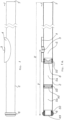
- a view of the flute headjoint 1 according to the invention is shown, which consists of a pipe section 2 configured similarly to, but longer than conventional headjoints, with an element 4 bounding an embouchure hole 3 being disposed on the pipe section 2.
- a so-called sonic chamber 5 is disposed in the part of the pipe section 2 of the flute headjoint 1 situated under the embouchure hole 3.
- the sonic chamber 5 is terminated at the side facing the crown 6 by a so-called tuning plug 8.
- the sonic chamber 5 is essentially a region with an approximate size of 4 cm, with the air blown in through the embouchure hole 3 flowing in the direction of the free end 7 of the pipe section 2 through the middle of this region.
- the body of the flute with the keywork adapted for playing the instrument is attached to the free end of the pipe section 2 of the flute headjoint 1.
- a tuning plug 8 In the region of the flute headjoint 1 near the crown 6 there is situated a tuning plug 8.
- the blown-in air collides against this plug and, taking a "u-tum" it flows in the direction of the free end 7:
- a fraction of the sound and oscillations is absorbed at this pipe section due to the configuration of the tuning plug 8.
- the tuning plug 8 applied with the flute headjoint 1 according to the invention is adapted for eliminating this effect, with the application of further additional components and configuration modifications allowing for improving the sound of the flute.
- a balance weight 40 In the resonator cavity 5a situated between the crown -6 and the tarring plug 8 there is disposed a balance weight 40, the role of which will be addressed later on.
- the resonator cavity 5a is larger, the larger resonator cavity 5a having a greater amplification effect on the sound of the flute.
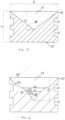
- Fig. 2 an example tuning plug 8 for a flute headjoint, not falling under the scope of the invention, is illustrated in section view.
- two or more grooves 9 are disposed on the outside surface of the cylindrical portion of the tuning plug 8.
- the two or more rubber rings placed into respective grooves 9 provide for improved centring of the tuning plug 8.
- the tuning plug 8 can be made of a wide range of materials including silver, gold, alpaca, copper, brass, zirconium, titanium, platinum, tantalum, bone, wood, or plastic.
- Metal tuning plugs 8 are preferably coated with rhodium which forms a strong; anti-scratch coating and provides an aesthetically pleasing, brilliant surface finish.
- the tuning plug 8 is preferably made of a compact, homogeneous or alloyed material.
- the tuning plug may also be made of sheet metal, but in that case a balance weight has to be applied in order to improve sound quality (see Fig. 16 ).
- the diameter d 1 of the conical portion 14a is 1-30 mm.
- R 1 1-58 mm
- R 2 1-58 mm
- the external configuration of the tuning plug 12 is identical to the external configuration of the tuning plug 8.
- the tuning plug can also have a bimetallic configuration:
- Such bimetallic tuning plug 15 configurations, made of two or more different metals or metal alloys, are disclosed in Figs. 4-7 and in Figs. 8-11 .
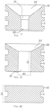
- Fig. 4 illustrates an upper portion 15, showing that the upper portion consists of a cylindrical stem portion 16 and a conically configured portion 17 that is connected to the stem portion 16.
- the transition between the stem portion 16 and the portion 17 is provided by an also conically configured portion 18:
- the configuration of the inner three-dimensional surface of the tuning plug 15 (see Fig. 5 ) is identical with the internal configuration of the single-material tuning plug 12 described in relation to Fig. 3 above.
- Fig. 6 a top plan view of the tuning plug 15 according to Fig. 4 is shown.
- Fig. 7 shows a section view of the bottom portion 19 of a bimetallic tuning plug 15.
- the bottom portion 19 is also configured identically to the external configuration of the tuning plugs 8 and 12, i.e. there are grooves 9disposed on the cylindrical surface.
- the internal configuration of the bottom portion 19 is similar to the configuration illustrated in Fig. 4 , i.e. a cylindrical portion 20 adapted for receiving the stem portion 16 is disposed in the bottom portion 19.
- the cylindrical portion 20 is connected with a portion 21 having a rounded-off flared surface which is terminated in a conical portion 22 that is adapted to support the portion 17 illustrated in Fig. 4 .
- the components of the tuning plug 15 are assembled by adhesive bonding or soldering, but rubber-ring or screw joints can also be implemented.
- Figs. 8-11 illustrate the configuration of a bimetallic tuning plug comprising a rubber-ring joint.
- Fig. 8 the upper portion of the tuning plug 23 is illustrated, the bottom portion of which is composed of a head portion 24, a stem portion 25 having a lower diameter than the head portion 24, a cylindrical portion 26 that has a diameter identical to the diameter of the head portion 24 and is connected to the stem portion 25, a conical portion 27, a further conical portion 28 that has a lower cone angle than the conical portion 27 and is connected thereto, and a cylindrical portion 29.
- the configuration of the inner three-dimensional surface of the upper portion of the tuning plug 23 is identical to the internal surface configuration of the tuning plug 12 described in relation to Fig. 3 above.
- Fig. 10 shows a top plan view of the tuning plug 23, while in Fig. 11 a section view of the bottom portion 30 of the tuning plug 23 is shown.
- the tuning plug 23 is assembled by first putting a rubber ring on the stem portion 25 of the upper portion, and then attaching the upper portion and the bottom portion 30. As the head portion 24 is inserted into the bore 31, the rubber ring is adhered to the wall of the bore 31, with the upper portion being be pushed into the bore 31 until the face 27 is fully supported against the portion 32. Being adhered to the wall of the bore 31, the rubber ring keeps the two portions attached.
- the upper and bottom portions are made from different metals or metal alloys.
- this solution allows that a wider timbre range can be achieved by the combination of metals, while it also reduces the cost of the flute because it is now not necessary to make the entire tuning plug of (very expensive) silver or gold.
- the tuning plug has a very significant influence on the sound produced playing the flute. Different metals have different effects on the quality and the characteristics of the flute sound.
- the crown 6 consists of two parts, a bottom portion 33 and an upper portion 34.
- the upper portion 34 consists of a cylindrical portion 36 and a portion 37 that is connected to the cylindrical portion 36 and is configured with a dome-like shape.
- a stepped bore 38 adapted to be connected to the bottom portion 33, the bore 38 ending in a narrower cylindrical bore 39.
- a membrane (not shown in the drawing) is disposed, the bottom and upper portions 33, 34 being joined by a screw joint.
- the membrane can be made of a wide range of materials, such as silver, gold, steel, aluminium, etc.
- the crown 6 can also be made from a wide range of different materials, i.e. copper, brass, zirconium, titanium, silver, gold, platinum, tantalum, alpaca, bone, wood, plastic, etc.
- the crown has a less significant effect on the sound quality of the flute, but the material of the crown subtly affects the quality of the produced sound.
- the above described shape of the crown allows that it can be easily and quickly replaced with another one even during a performance, i.e. a different crown can be inserted into the flute headjoint in approximately 30 seconds, which allows for achieving a sound quality that better match the next piece.
- the flute according to the invention comprising the novel tuning plug and crown has much, better sound quality compared to a conventional flute.
- the flute according to the invention comprising the novel tuning plug and crown has much, better sound quality compared to a conventional flute.
- the flute according to the invention has stronger, more dynamic, clearer, more flexible sound both piano and forte notes can be played more easily. A lot less pitch compensation is necessary.
- the tuning plug and crown modified in the above described manner make a very marked difference for players.
- the flute headjoint according to the invention can also be provided with additional components that positively affect the use and the sound of the flute.
- Such an additional component can be a balance weight 40 inserted into the resonator cavity between the tuning plug and the crown.
- a groove 41 is machined in the lateral surface of the balance weight 40, with a rubber ring seated in the groove 41 being adapted to retain the balance weight at the desired position.
- the balance weight can also be made of a wide range of materials, i.e. of alpaca, aluminium, copper, brass, silver, gold, titanium, zirconium.
- balance weights made of copper, brass or alpaca have to be coated as an anti-corrosion measure and to prevent aluminium oxidation.
- extension piece adapted to be attached to the flute headjoint according to the invention (and to any other flute headjoint manufactured earlier) a special-size flute having a headjoint with greater length than conventional headjoints can be provided.
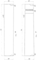
- extension pieces 42 and 43 are depicted in Figs. 17 and 18 .
- the extension pieces 42 and 43 are implemented as thin-walled pipes that are adapted to be temporarily inserted into the flute headjoint 1 replacing the crown 6 and are retained by a rubber ring.
- the extension piece 43 illustrated in Fig. 18 is also implemented as a thin-walled pipe adapted to replace the crown 6 such that it is temporarily placed on the flute headjoint from outside. It has a length L 7 between 2 cm and 28 cm.
- the extension pieces 42,43 can be switched quickly and easily, even during a concert.
- the metal alloys or high-purity metals provide an improved sound that is different from the average flute sound, is bigger and more beautiful.
Landscapes
- Physics & Mathematics (AREA)
- Engineering & Computer Science (AREA)
- Acoustics & Sound (AREA)
- Multimedia (AREA)
- Pens And Brushes (AREA)
- Coupling Device And Connection With Printed Circuit (AREA)
- Earth Drilling (AREA)
- Toys (AREA)
- Golf Clubs (AREA)
- Closures For Containers (AREA)
Claims (14)
- Flötenkopfstück, Folgendes umfassend:einen zylindrischen Rohrabschnitt (2),ein durch ein Verstärkungselement (4) begrenztes Mundloch (3),eine Kopfschraube (6), die dazu eingerichtet ist, den Rohrabschnitt (2) links vom Mundloch (3) abzuschließen,einen konkaven Stimmkorken (8, 12, 15, 23), der in dem Rohrabschnitt (2) in einer Klangkammer (5) angeordnet ist, die unter dem Mundloch (3) angeordnet ist,ein Gegengewicht (40), das dazu eingerichtet ist, in einem Resonatorhohlraum (5a) zwischen dem Stimmkorken (8, 12, 15, 23) und der Kopfschraube (6) angeordnet zu sein, undein zusätzliches Verlängerungsstück (42, 43);dadurch gekennzeichnet, dassdie Kopfschraube (6) in Richtung des Rohrabschnitts (2) der Flöte offen ist undder Stimmkorken (8, 12, 15, 23) ein zylindrischer Körper ist, der mit seiner Stirnseite dem Mundloch (3) zugewandt angeordnet ist und eine versenkte, dreidimensionale Konfiguration mit einem inneren konischen Abschnitt (14a) aufweist, wobei ein kegelstumpfförmiger Abschnitt (14b) mit dem inneren konischen Abschnitt (14a) verbunden ist, mit einem Querschnitt mit einem ersten Radius entlang der Richtung des Rohrabschnitts und einem konkaven, aufgeweiteten Abschnitt (14c), der mit dem kegelstumpfförmigen Abschnitt (14b) verbunden ist einem Querschnitt mit einem zweiten Radius entlang der Richtung des Rohrabschnitts (2) aufweist.
- Flötenkopfstück nach Anspruch 1, dadurch gekennzeichnet, dass der zylindrische Rohrabschnitt (2) eine Länge im Bereich von 220 mm bis 450 mm aufweist.
- Flötenkopfstück nach Anspruch 1, dadurch gekennzeichnet, dass die Kopfschraube (6) aus zwei hohlen Abschnitten, einem unteren hohlen Abschnitt (33) und einem oberen hohlen Abschnitt (34), besteht, wobei der untere Abschnitt (33) und der obere Abschnitt (34) über eine lösbare Verbindung miteinander verbunden sind, wobei eine Membran zwischen dem unteren Abschnitt (33) und dem oberen Abschnitt (34) angeordnet ist und wobei eine Nut (9) auf der zylindrischen Fläche des unteren Abschnitts (33) angeordnet ist.
- Flötenkopfstück (1) nach einem der Ansprüche 1-3, dadurch gekennzeichnet, dass der Stimmkorken (8) Nuten (9) umfasst, die zur Aufnahme von an dessen zylindrischem Körper angeordneten Gummiringen eingerichtet sind, wobei die Oberfläche des Stimmkorkens dem Mundloch (3) mit einer nach innen verjüngten Konfiguration zugewandt ist.
- Flötenkopfstück (1) nach einem der Ansprüche 1-3, dadurch gekennzeichnet, dass der Stimmkorken (12) Nuten (9) umfasst, die auf seiner zylindrischen Fläche angeordnet sind.
- Flötenkopfstück (1) nach einem der Ansprüche 1 oder 2, dadurch gekennzeichnet, dass der Stimmkorken (15, 23) aus zwei Abschnitten, einem oberen Abschnitt (19) und einem unteren Abschnitt (30), besteht, die fest oder mittels einer lösbaren Verbindung, beispielsweise mittels einer Schraubverbindung, miteinander verbunden sind.
- Flötenkopfstück (1) nach Anspruch 6, dadurch gekennzeichnet, dass der obere Abschnitt des Stimmkorkens (12) aus einem Stammabschnitt (16) und dem aufwärts verjüngten Abschnitt (17), der über einen Zwischenabschnitt (18) mit dem Stammabschnitt(16) verbunden ist, ausgebildet ist, mit einer aus dem inneren konischen Abschnitt (14a) bestehenden Aussparung, wobei der kegelstumpfförmige Abschnitt (14b) und der konkave, aufgeweitete Abschnitt (14c) im Inneren des oberen Abschnitts angeordnet sind und wobei sich ein Verbindungshohlraum, der zum Aufnehmen und Halten des oberen Abschnitts (30) eingerichtet ist, entlang der gesamten Höhe des unteren Abschnitts (19) erstreckt und im unteren Abschnitt (19) angeordnet ist.
- Flötenkopfstück (1) nach Anspruch 6, dadurch gekennzeichnet, dass der obere Abschnitt des Stimmkorkens (23) aus einem Kopfabschnitt (24), einem Stammabschnitt (25), einem zylindrischen Abschnitt (26) und einem nach außen verjüngten Abschnitt (28), der in einem zylindrischen Abschnitt (29) endet, besteht, mit einer aus dem inneren konischen Abschnitt (14a) bestehenden Aussparung, wobei der kegelstumpfförmige Abschnitt (14b) und der konkave, aufgeweitete Abschnitt (14c) im Inneren des oberen Abschnitts angeordnet sind und wobei eine innere Bohrung (31), die zum Aufnehmen des oberen Abschnitts eingerichtet ist, und ein mit der Bohrung (31) verbundener konischer Abschnitt (32) im unteren Abschnitt (30) angeordnet sind.
- Flötenkopfstück (1) nach Anspruch 8, dadurch gekennzeichnet, dass eine lösbare Verbindung vorhanden ist, die vorzugsweise unter Verwendung eines Gummirings zwischen dem oberen und unteren Abschnitt (30) des Stimmkorkens (23) umgesetzt ist.
- Flötenkopfstück (1) nach einem der Ansprüche 1-9, dadurch gekennzeichnet, dass das Gegengewicht (40), das zwischen der Kopfschraube (6) und dem Stimmkorken (8, 12, 15, 23) innerhalb des Resonatorhohlraums (5a) angeordnet ist, ein scheiben- oder ringförmiger Körper ist, der eine oder mehrere Nuten (41) umfasst, die zur Aufnahme jeweils eines auf dessen Außenseite angeordneten Gummirings eingerichtet ist.
- Flötenkopfstück (1) nach einem der Ansprüche 1-10, dadurch gekennzeichnet, dass das Verlängerungsstück (42) ein dünnwandiges Rohr ist, an dessen einem Ende (44) eine Nut (48) angeordnet ist, wobei dessen anderes Ende (45) zur Aufnahme der Kopfschraube (6) eingerichtet ist.
- Flötenkopfstück (1) nach einem der Ansprüche 1-10, dadurch gekennzeichnet, dass das Verlängerungsstück (43) ein dünnwandiges Rohr ist, wobei dessen mit dem Flötenkopfstück (1) verbundenes Ende (46) eine verjüngte Konfiguration aufweist, wobei dessen anderes Ende (47) zur Aufnahme der Kopfschraube (6) eingerichtet ist.
- Flötenkopfstück (1) nach einem der Ansprüche 1-12, dadurch gekennzeichnet, dass die Kopfschraube (6), der Stimmkorken (8, 12, 15, 23), das Gegengewicht (40) und das Verlängerungsstück (42, 43) aus folgendem Material gefertigt sind: Gold, Silber, Alpaka, Kupfer, Messing, Aluminium, Stahl, Titan, Platin, Tantal, Zirkonium, Holz, Knochen, Kunststoff.
- Flötenkopfstück (1) nach einem der Ansprüche 1-13, dadurch gekennzeichnet, dass die Kopfschraube (6), der Stimmkorken (8, 12, 15, 23), das Gegengewicht (40) und das Verlängerungsstück (42) mittels Gummiringen, die in Nuten (9, 41, 48) angeordnet sind, die in dessen zylindrische Oberfläche gearbeitet wurden, am Flötenkopfstück (1) befestigt sind.
Applications Claiming Priority (2)
| Application Number | Priority Date | Filing Date | Title |
|---|---|---|---|
| HU1500480A HU230939B1 (hu) | 2015-10-19 | 2015-10-19 | Reform fuvolafej |
| PCT/HU2016/000066 WO2017068380A1 (en) | 2015-10-19 | 2016-10-04 | Improved flute headjoint |
Publications (3)
| Publication Number | Publication Date |
|---|---|
| EP3365889A1 EP3365889A1 (de) | 2018-08-29 |
| EP3365889C0 EP3365889C0 (de) | 2023-09-06 |
| EP3365889B1 true EP3365889B1 (de) | 2023-09-06 |
Family
ID=89991959
Family Applications (1)
| Application Number | Title | Priority Date | Filing Date |
|---|---|---|---|
| EP16795131.8A Active EP3365889B1 (de) | 2015-10-19 | 2016-10-04 | Verbessertes kopfstück für flöte |
Country Status (6)
| Country | Link |
|---|---|
| US (1) | US10380978B2 (de) |
| EP (1) | EP3365889B1 (de) |
| JP (1) | JP6867631B2 (de) |
| CN (1) | CN108292495B (de) |
| HU (1) | HU230939B1 (de) |
| WO (1) | WO2017068380A1 (de) |
Families Citing this family (1)
| Publication number | Priority date | Publication date | Assignee | Title |
|---|---|---|---|---|
| JP6782017B2 (ja) * | 2017-11-07 | 2020-11-11 | 株式会社 アコースティックイノベーションズ | 呼吸音響装置 |
Citations (2)
| Publication number | Priority date | Publication date | Assignee | Title |
|---|---|---|---|---|
| JP3023298U (ja) * | 1995-09-28 | 1996-04-16 | 株式会社三響フルート製作所 | フルートの頭部管 |
| JP3135624U (ja) * | 2007-07-12 | 2007-09-20 | 正治 相原 | フルート属の頭部管に装着する部材 |
Family Cites Families (15)
| Publication number | Priority date | Publication date | Assignee | Title |
|---|---|---|---|---|
| FR2239929A5 (en) * | 1973-08-03 | 1975-02-28 | Barjon Jean | Stop for end of flute - has concave inner face to give better performance uniform over whole register |
| US4240320A (en) * | 1980-03-21 | 1980-12-23 | Pellerite James J | Headjoint stopper |
| FR2529364B1 (fr) * | 1982-06-23 | 1985-07-05 | Ferron E Ets | Procede pour ameliorer l'emission de notes predeterminees d'un instrument a vent et instrument appliquant ce procede |
| GB8503692D0 (en) * | 1985-02-13 | 1985-03-13 | Senior I S T | Musical instruments |
| KR100392287B1 (ko) * | 2000-04-17 | 2003-07-22 | 임재동 | 플루트의 음 조절 장치 |
| JP3496003B2 (ja) * | 2001-06-19 | 2004-02-09 | 増永 幸子 | フルート |
| WO2005071661A2 (en) * | 2004-01-21 | 2005-08-04 | Flauto Forte B.V. | Flute |
| JP4567494B2 (ja) * | 2004-03-29 | 2010-10-20 | 西藤 孝夫 | 笛 |
| JP2007047716A (ja) * | 2005-08-05 | 2007-02-22 | Bunkichi Natsuki | 窪みつき反射筒つき管楽器 |
| JP2007241202A (ja) * | 2006-03-06 | 2007-09-20 | Chieko Royama | フルート重心バランサー |
| JP5227659B2 (ja) * | 2008-04-22 | 2013-07-03 | 文吉 夏木 | 筒状部材 |
| US20100018380A1 (en) * | 2008-07-23 | 2010-01-28 | Mark Seidman | Acoustically Pleasing Headjoint Stopper for a Transverse Flute |
| US8653347B1 (en) * | 2012-08-10 | 2014-02-18 | Gary Wayne Lewis | Headjoint crown assembly with extension unit |
| CN202905131U (zh) * | 2012-11-23 | 2013-04-24 | 陈国栋 | 木质长笛 |
| CN104021778A (zh) * | 2014-06-17 | 2014-09-03 | 河北金音乐器集团有限公司 | 速学长笛笛头 |
-
2015
- 2015-10-19 HU HU1500480A patent/HU230939B1/hu unknown
-
2016
- 2016-10-04 EP EP16795131.8A patent/EP3365889B1/de active Active
- 2016-10-04 CN CN201680068570.1A patent/CN108292495B/zh active Active
- 2016-10-04 US US15/769,029 patent/US10380978B2/en active Active
- 2016-10-04 WO PCT/HU2016/000066 patent/WO2017068380A1/en not_active Ceased
- 2016-10-04 JP JP2018521313A patent/JP6867631B2/ja active Active
Patent Citations (2)
| Publication number | Priority date | Publication date | Assignee | Title |
|---|---|---|---|---|
| JP3023298U (ja) * | 1995-09-28 | 1996-04-16 | 株式会社三響フルート製作所 | フルートの頭部管 |
| JP3135624U (ja) * | 2007-07-12 | 2007-09-20 | 正治 相原 | フルート属の頭部管に装着する部材 |
Also Published As
| Publication number | Publication date |
|---|---|
| JP2018531432A (ja) | 2018-10-25 |
| EP3365889C0 (de) | 2023-09-06 |
| US20180308459A1 (en) | 2018-10-25 |
| WO2017068380A1 (en) | 2017-04-27 |
| US10380978B2 (en) | 2019-08-13 |
| CN108292495B (zh) | 2022-08-16 |
| EP3365889A1 (de) | 2018-08-29 |
| HUP1500480A2 (en) | 2017-04-28 |
| CN108292495A (zh) | 2018-07-17 |
| JP6867631B2 (ja) | 2021-04-28 |
| HU230939B1 (hu) | 2019-04-29 |
Similar Documents
| Publication | Publication Date | Title |
|---|---|---|
| JP2883191B2 (ja) | ゴルフクラブの頭部を柄部に固定する装置 | |
| US7705227B2 (en) | Mouthpiece of brass instrument | |
| US20070095194A1 (en) | Accessories or actuating elements for, or components of, musical instruments | |
| US10380978B2 (en) | Flute headjoint | |
| US7326840B2 (en) | Mouthpiece for a musical instrument | |
| US7923618B2 (en) | “Eclipse ligature” for single reed musical instruments | |
| US4395933A (en) | Mouthpiece for brass-wind instruments | |
| US20060272473A1 (en) | Mouthpiece for a wind instrument | |
| US12387698B2 (en) | Chanter of a wind instrument | |
| KR101405991B1 (ko) | 울림통을 갖는 악기용 마우스피스 | |
| JP2018531432A6 (ja) | 改善されたフルートヘッドジョイント | |
| JP2009106650A (ja) | ゴルフクラブ | |
| JP4440703B2 (ja) | マウスピース | |
| US12249303B2 (en) | High-mass elliptical cup mouthpiece with conical section for brass musical instruments | |
| US4422364A (en) | Fipple type headjoint assembly for use with existing transverse flutes | |
| US11145282B2 (en) | Woodwind mouthpiece | |
| US20110126691A1 (en) | Tunable mouthpiece for a brass instrument | |
| KR20230171129A (ko) | 색소폰용 마우스피스 키트 | |
| US20160067571A1 (en) | Golf club head with sound tuning element | |
| KR102181661B1 (ko) | 색소폰용 울림통형 마우스피스 | |
| US358542A (en) | Chaeles p | |
| KR200481069Y1 (ko) | 색소폰용 마우스피스 | |
| JP7039043B2 (ja) | 息漏れ防止器具 | |
| JPWO2006027819A1 (ja) | 唄口、接続管及びそれを有する管楽器 | |
| US787127A (en) | Mouthpiece for clarinets. |
Legal Events
| Date | Code | Title | Description |
|---|---|---|---|
| STAA | Information on the status of an ep patent application or granted ep patent |
Free format text: STATUS: UNKNOWN |
|
| STAA | Information on the status of an ep patent application or granted ep patent |
Free format text: STATUS: THE INTERNATIONAL PUBLICATION HAS BEEN MADE |
|
| PUAI | Public reference made under article 153(3) epc to a published international application that has entered the european phase |
Free format text: ORIGINAL CODE: 0009012 |
|
| STAA | Information on the status of an ep patent application or granted ep patent |
Free format text: STATUS: REQUEST FOR EXAMINATION WAS MADE |
|
| 17P | Request for examination filed |
Effective date: 20180410 |
|
| AK | Designated contracting states |
Kind code of ref document: A1 Designated state(s): AL AT BE BG CH CY CZ DE DK EE ES FI FR GB GR HR HU IE IS IT LI LT LU LV MC MK MT NL NO PL PT RO RS SE SI SK SM TR |
|
| AX | Request for extension of the european patent |
Extension state: BA ME |
|
| DAV | Request for validation of the european patent (deleted) | ||
| DAX | Request for extension of the european patent (deleted) | ||
| STAA | Information on the status of an ep patent application or granted ep patent |
Free format text: STATUS: EXAMINATION IS IN PROGRESS |
|
| 17Q | First examination report despatched |
Effective date: 20210930 |
|
| REG | Reference to a national code |
Ref country code: DE Ref legal event code: R079 Free format text: PREVIOUS MAIN CLASS: G10D0009020000 Ipc: G10D0007026000 Ref document number: 602016082574 Country of ref document: DE |
|
| RIC1 | Information provided on ipc code assigned before grant |
Ipc: G10D 9/02 20060101ALI20230130BHEP Ipc: G10D 9/01 20200101ALI20230130BHEP Ipc: G10D 7/026 20200101AFI20230130BHEP |
|
| GRAP | Despatch of communication of intention to grant a patent |
Free format text: ORIGINAL CODE: EPIDOSNIGR1 |
|
| STAA | Information on the status of an ep patent application or granted ep patent |
Free format text: STATUS: GRANT OF PATENT IS INTENDED |
|
| INTG | Intention to grant announced |
Effective date: 20230331 |
|
| GRAS | Grant fee paid |
Free format text: ORIGINAL CODE: EPIDOSNIGR3 |
|
| GRAA | (expected) grant |
Free format text: ORIGINAL CODE: 0009210 |
|
| STAA | Information on the status of an ep patent application or granted ep patent |
Free format text: STATUS: THE PATENT HAS BEEN GRANTED |
|
| AK | Designated contracting states |
Kind code of ref document: B1 Designated state(s): AL AT BE BG CH CY CZ DE DK EE ES FI FR GB GR HR HU IE IS IT LI LT LU LV MC MK MT NL NO PL PT RO RS SE SI SK SM TR |
|
| REG | Reference to a national code |
Ref country code: GB Ref legal event code: FG4D |
|
| REG | Reference to a national code |
Ref country code: CH Ref legal event code: EP |
|
| REG | Reference to a national code |
Ref country code: DE Ref legal event code: R096 Ref document number: 602016082574 Country of ref document: DE |
|
| REG | Reference to a national code |
Ref country code: IE Ref legal event code: FG4D |
|
| U01 | Request for unitary effect filed |
Effective date: 20230926 |
|
| U07 | Unitary effect registered |
Designated state(s): AT BE BG DE DK EE FI FR IT LT LU LV MT NL PT SE SI Effective date: 20231004 |
|
| U20 | Renewal fee for the european patent with unitary effect paid |
Year of fee payment: 8 Effective date: 20231002 |
|
| PG25 | Lapsed in a contracting state [announced via postgrant information from national office to epo] |
Ref country code: GR Free format text: LAPSE BECAUSE OF FAILURE TO SUBMIT A TRANSLATION OF THE DESCRIPTION OR TO PAY THE FEE WITHIN THE PRESCRIBED TIME-LIMIT Effective date: 20231207 |
|
| PG25 | Lapsed in a contracting state [announced via postgrant information from national office to epo] |
Ref country code: RS Free format text: LAPSE BECAUSE OF FAILURE TO SUBMIT A TRANSLATION OF THE DESCRIPTION OR TO PAY THE FEE WITHIN THE PRESCRIBED TIME-LIMIT Effective date: 20230906 Ref country code: NO Free format text: LAPSE BECAUSE OF FAILURE TO SUBMIT A TRANSLATION OF THE DESCRIPTION OR TO PAY THE FEE WITHIN THE PRESCRIBED TIME-LIMIT Effective date: 20231206 Ref country code: HR Free format text: LAPSE BECAUSE OF FAILURE TO SUBMIT A TRANSLATION OF THE DESCRIPTION OR TO PAY THE FEE WITHIN THE PRESCRIBED TIME-LIMIT Effective date: 20230906 Ref country code: GR Free format text: LAPSE BECAUSE OF FAILURE TO SUBMIT A TRANSLATION OF THE DESCRIPTION OR TO PAY THE FEE WITHIN THE PRESCRIBED TIME-LIMIT Effective date: 20231207 |
|
| PG25 | Lapsed in a contracting state [announced via postgrant information from national office to epo] |
Ref country code: IS Free format text: LAPSE BECAUSE OF FAILURE TO SUBMIT A TRANSLATION OF THE DESCRIPTION OR TO PAY THE FEE WITHIN THE PRESCRIBED TIME-LIMIT Effective date: 20240106 |
|
| PG25 | Lapsed in a contracting state [announced via postgrant information from national office to epo] |
Ref country code: ES Free format text: LAPSE BECAUSE OF FAILURE TO SUBMIT A TRANSLATION OF THE DESCRIPTION OR TO PAY THE FEE WITHIN THE PRESCRIBED TIME-LIMIT Effective date: 20230906 |
|
| PG25 | Lapsed in a contracting state [announced via postgrant information from national office to epo] |
Ref country code: SM Free format text: LAPSE BECAUSE OF FAILURE TO SUBMIT A TRANSLATION OF THE DESCRIPTION OR TO PAY THE FEE WITHIN THE PRESCRIBED TIME-LIMIT Effective date: 20230906 Ref country code: RO Free format text: LAPSE BECAUSE OF FAILURE TO SUBMIT A TRANSLATION OF THE DESCRIPTION OR TO PAY THE FEE WITHIN THE PRESCRIBED TIME-LIMIT Effective date: 20230906 Ref country code: IS Free format text: LAPSE BECAUSE OF FAILURE TO SUBMIT A TRANSLATION OF THE DESCRIPTION OR TO PAY THE FEE WITHIN THE PRESCRIBED TIME-LIMIT Effective date: 20240106 Ref country code: ES Free format text: LAPSE BECAUSE OF FAILURE TO SUBMIT A TRANSLATION OF THE DESCRIPTION OR TO PAY THE FEE WITHIN THE PRESCRIBED TIME-LIMIT Effective date: 20230906 Ref country code: CZ Free format text: LAPSE BECAUSE OF FAILURE TO SUBMIT A TRANSLATION OF THE DESCRIPTION OR TO PAY THE FEE WITHIN THE PRESCRIBED TIME-LIMIT Effective date: 20230906 Ref country code: SK Free format text: LAPSE BECAUSE OF FAILURE TO SUBMIT A TRANSLATION OF THE DESCRIPTION OR TO PAY THE FEE WITHIN THE PRESCRIBED TIME-LIMIT Effective date: 20230906 |
|
| PG25 | Lapsed in a contracting state [announced via postgrant information from national office to epo] |
Ref country code: PL Free format text: LAPSE BECAUSE OF FAILURE TO SUBMIT A TRANSLATION OF THE DESCRIPTION OR TO PAY THE FEE WITHIN THE PRESCRIBED TIME-LIMIT Effective date: 20230906 |
|
| REG | Reference to a national code |
Ref country code: CH Ref legal event code: PL |
|
| REG | Reference to a national code |
Ref country code: DE Ref legal event code: R097 Ref document number: 602016082574 Country of ref document: DE |
|
| PG25 | Lapsed in a contracting state [announced via postgrant information from national office to epo] |
Ref country code: MC Free format text: LAPSE BECAUSE OF FAILURE TO SUBMIT A TRANSLATION OF THE DESCRIPTION OR TO PAY THE FEE WITHIN THE PRESCRIBED TIME-LIMIT Effective date: 20230906 |
|
| PLBE | No opposition filed within time limit |
Free format text: ORIGINAL CODE: 0009261 |
|
| STAA | Information on the status of an ep patent application or granted ep patent |
Free format text: STATUS: NO OPPOSITION FILED WITHIN TIME LIMIT |
|
| PG25 | Lapsed in a contracting state [announced via postgrant information from national office to epo] |
Ref country code: CH Free format text: LAPSE BECAUSE OF NON-PAYMENT OF DUE FEES Effective date: 20231031 |
|
| PG25 | Lapsed in a contracting state [announced via postgrant information from national office to epo] |
Ref country code: MC Free format text: LAPSE BECAUSE OF FAILURE TO SUBMIT A TRANSLATION OF THE DESCRIPTION OR TO PAY THE FEE WITHIN THE PRESCRIBED TIME-LIMIT Effective date: 20230906 Ref country code: CH Free format text: LAPSE BECAUSE OF NON-PAYMENT OF DUE FEES Effective date: 20231031 |
|
| 26N | No opposition filed |
Effective date: 20240607 |
|
| GBPC | Gb: european patent ceased through non-payment of renewal fee |
Effective date: 20231206 |
|
| PG25 | Lapsed in a contracting state [announced via postgrant information from national office to epo] |
Ref country code: IE Free format text: LAPSE BECAUSE OF NON-PAYMENT OF DUE FEES Effective date: 20231004 |
|
| PG25 | Lapsed in a contracting state [announced via postgrant information from national office to epo] |
Ref country code: GB Free format text: LAPSE BECAUSE OF NON-PAYMENT OF DUE FEES Effective date: 20231206 |
|
| PG25 | Lapsed in a contracting state [announced via postgrant information from national office to epo] |
Ref country code: IE Free format text: LAPSE BECAUSE OF NON-PAYMENT OF DUE FEES Effective date: 20231004 Ref country code: GB Free format text: LAPSE BECAUSE OF NON-PAYMENT OF DUE FEES Effective date: 20231206 |
|
| U20 | Renewal fee for the european patent with unitary effect paid |
Year of fee payment: 9 Effective date: 20241003 |
|
| PG25 | Lapsed in a contracting state [announced via postgrant information from national office to epo] |
Ref country code: CY Free format text: LAPSE BECAUSE OF FAILURE TO SUBMIT A TRANSLATION OF THE DESCRIPTION OR TO PAY THE FEE WITHIN THE PRESCRIBED TIME-LIMIT; INVALID AB INITIO Effective date: 20161004 |
|
| PG25 | Lapsed in a contracting state [announced via postgrant information from national office to epo] |
Ref country code: HU Free format text: LAPSE BECAUSE OF FAILURE TO SUBMIT A TRANSLATION OF THE DESCRIPTION OR TO PAY THE FEE WITHIN THE PRESCRIBED TIME-LIMIT; INVALID AB INITIO Effective date: 20161004 |
|
| U20 | Renewal fee for the european patent with unitary effect paid |
Year of fee payment: 10 Effective date: 20251008 |
|
| PG25 | Lapsed in a contracting state [announced via postgrant information from national office to epo] |
Ref country code: TR Free format text: LAPSE BECAUSE OF FAILURE TO SUBMIT A TRANSLATION OF THE DESCRIPTION OR TO PAY THE FEE WITHIN THE PRESCRIBED TIME-LIMIT Effective date: 20230906 |