EP3364485B1 - Aufspannmodul für festoxid-brennstoffzelle - Google Patents
Aufspannmodul für festoxid-brennstoffzelle Download PDFInfo
- Publication number
- EP3364485B1 EP3364485B1 EP17843970.9A EP17843970A EP3364485B1 EP 3364485 B1 EP3364485 B1 EP 3364485B1 EP 17843970 A EP17843970 A EP 17843970A EP 3364485 B1 EP3364485 B1 EP 3364485B1
- Authority
- EP
- European Patent Office
- Prior art keywords
- jig
- sealant
- unit
- oxygen
- hydrogen
- Prior art date
- Legal status (The legal status is an assumption and is not a legal conclusion. Google has not performed a legal analysis and makes no representation as to the accuracy of the status listed.)
- Active
Links
Images
Classifications
-
- H—ELECTRICITY
- H01—ELECTRIC ELEMENTS
- H01M—PROCESSES OR MEANS, e.g. BATTERIES, FOR THE DIRECT CONVERSION OF CHEMICAL ENERGY INTO ELECTRICAL ENERGY
- H01M8/00—Fuel cells; Manufacture thereof
- H01M8/02—Details
- H01M8/0271—Sealing or supporting means around electrodes, matrices or membranes
- H01M8/0273—Sealing or supporting means around electrodes, matrices or membranes with sealing or supporting means in the form of a frame
-
- H—ELECTRICITY
- H01—ELECTRIC ELEMENTS
- H01M—PROCESSES OR MEANS, e.g. BATTERIES, FOR THE DIRECT CONVERSION OF CHEMICAL ENERGY INTO ELECTRICAL ENERGY
- H01M8/00—Fuel cells; Manufacture thereof
- H01M8/10—Fuel cells with solid electrolytes
- H01M8/12—Fuel cells with solid electrolytes operating at high temperature, e.g. with stabilised ZrO2 electrolyte
-
- H—ELECTRICITY
- H01—ELECTRIC ELEMENTS
- H01M—PROCESSES OR MEANS, e.g. BATTERIES, FOR THE DIRECT CONVERSION OF CHEMICAL ENERGY INTO ELECTRICAL ENERGY
- H01M8/00—Fuel cells; Manufacture thereof
- H01M8/04—Auxiliary arrangements, e.g. for control of pressure or for circulation of fluids
- H01M8/04298—Processes for controlling fuel cells or fuel cell systems
- H01M8/04305—Modeling, demonstration models of fuel cells, e.g. for training purposes
-
- H—ELECTRICITY
- H01—ELECTRIC ELEMENTS
- H01M—PROCESSES OR MEANS, e.g. BATTERIES, FOR THE DIRECT CONVERSION OF CHEMICAL ENERGY INTO ELECTRICAL ENERGY
- H01M8/00—Fuel cells; Manufacture thereof
- H01M8/04—Auxiliary arrangements, e.g. for control of pressure or for circulation of fluids
- H01M8/04298—Processes for controlling fuel cells or fuel cell systems
- H01M8/04313—Processes for controlling fuel cells or fuel cell systems characterised by the detection or assessment of variables; characterised by the detection or assessment of failure or abnormal function
- H01M8/04664—Failure or abnormal function
- H01M8/04671—Failure or abnormal function of the individual fuel cell
-
- H—ELECTRICITY
- H01—ELECTRIC ELEMENTS
- H01M—PROCESSES OR MEANS, e.g. BATTERIES, FOR THE DIRECT CONVERSION OF CHEMICAL ENERGY INTO ELECTRICAL ENERGY
- H01M8/00—Fuel cells; Manufacture thereof
- H01M8/04—Auxiliary arrangements, e.g. for control of pressure or for circulation of fluids
- H01M8/04298—Processes for controlling fuel cells or fuel cell systems
- H01M8/04694—Processes for controlling fuel cells or fuel cell systems characterised by variables to be controlled
- H01M8/04746—Pressure; Flow
- H01M8/04753—Pressure; Flow of fuel cell reactants
-
- H—ELECTRICITY
- H01—ELECTRIC ELEMENTS
- H01M—PROCESSES OR MEANS, e.g. BATTERIES, FOR THE DIRECT CONVERSION OF CHEMICAL ENERGY INTO ELECTRICAL ENERGY
- H01M8/00—Fuel cells; Manufacture thereof
- H01M8/10—Fuel cells with solid electrolytes
- H01M8/12—Fuel cells with solid electrolytes operating at high temperature, e.g. with stabilised ZrO2 electrolyte
- H01M2008/1293—Fuel cells with solid oxide electrolytes
-
- H—ELECTRICITY
- H01—ELECTRIC ELEMENTS
- H01M—PROCESSES OR MEANS, e.g. BATTERIES, FOR THE DIRECT CONVERSION OF CHEMICAL ENERGY INTO ELECTRICAL ENERGY
- H01M8/00—Fuel cells; Manufacture thereof
- H01M8/002—Shape, form of a fuel cell
- H01M8/004—Cylindrical, tubular or wound
-
- Y—GENERAL TAGGING OF NEW TECHNOLOGICAL DEVELOPMENTS; GENERAL TAGGING OF CROSS-SECTIONAL TECHNOLOGIES SPANNING OVER SEVERAL SECTIONS OF THE IPC; TECHNICAL SUBJECTS COVERED BY FORMER USPC CROSS-REFERENCE ART COLLECTIONS [XRACs] AND DIGESTS
- Y02—TECHNOLOGIES OR APPLICATIONS FOR MITIGATION OR ADAPTATION AGAINST CLIMATE CHANGE
- Y02E—REDUCTION OF GREENHOUSE GAS [GHG] EMISSIONS, RELATED TO ENERGY GENERATION, TRANSMISSION OR DISTRIBUTION
- Y02E60/00—Enabling technologies; Technologies with a potential or indirect contribution to GHG emissions mitigation
- Y02E60/30—Hydrogen technology
- Y02E60/50—Fuel cells
Definitions
- the present invention relates to a technology for a jig module for a solid oxide fuel cell, and more particularly, to a jig module for a solid oxide fuel cell in which a press is bonded to upper and lower jigs of a jig which evaluates a characteristic of a fuel cell so that gas leakage through a sealant and attachment strength of the sealant and a performance of a unit cell are simultaneously evaluated by using one jig.
- the fuel cell is a device which directly produces electricity through an electrochemical reaction of hydrogen and oxygen in the air, and is an energy source which is eco-friendly, has high energy efficiency, and has a high value added through technology development.
- the solid oxide fuel cell which is a third-generation fuel cell has advantages in that the solid oxide fuel cell does not need a complex external reforming system as compared with other fuel cells, and does not use a noble metal electrode catalyst such as platinum, and is not corroded due to a liquid electrolyte, so that various operating problems caused in a low temperature fuel cell may be minimized, and the solid oxide fuel cell may maintain an operating temperature through appropriate insulation at the time of a high temperature operation and use various fuels.
- a configuration of the solid oxide fuel cell is formed of a unit cell, which includes a fuel electrode, an electrolyte, and an air electrode, and a connecting material, which connects unit cells.
- the sealant serves to prevent fuel gas supplied to a fuel electrode (anode) between an electrolyte layer and a metal connector and air supplied to an air electrode from being mixed with each other and to prevent gas leakage to the outside.
- the sealant is a very important core component for ensuring thermal mechanical stability and a long lifespan of a stack, and operates at a high temperature of 600°C to 800°C, so that importance of development of the sealant is increased.
- the related art has a problem in that in order to evaluate a characteristic of the sealant, performances of a fuel cell and a sealant are measured not only using the sealant, but also using fuel cell having a complex structure in which all components such as a unit cell, a window frame (or a separator), and an interconnector are laminated.
- the solid oxide fuel cell is classified into a planar type, a cylindrical type, and a planar tubular type, and there is a problem in that a structure of the device which measures a performance and a characteristic is subdivided according to the type.
- a device for measuring a characteristic of a solid oxide fuel cell in the related art may use one device to make only one measurement to measure a performance of the fuel cell or evaluate whether gas is leaked through the sealant, so that there is a problem in that in order to measure various performances of the solid oxide fuel cell and a component thereof, the device needs to be converted into a measuring device suitable therefor.
- JP 2010 123566 A discloses a jig module according to the preamble of claim 1
- KR 2015 0055648 discloses a jig module for testing SOFCs with a mass flow meter which measures a flow rate of hydrogen which flows into the hydrogen supply pipe, and a press part which is not further illustrated or described.
- the present invention has been contrived to solve the above-described problems, and an object of the present invention is to provide a jig module for a solid oxide fuel cell in which a press unit is bonded to upper/lower jigs in which a gas outlet pipe and a gas inlet pipe are formed to measure complex characteristics using one jig module for a solid oxide fuel cell such as evaluation of gas leakage through a sealant and attachment strength of a sealant and evaluation of performance of a unit cell.
- a jig module for a solid oxide fuel cell including: a lower jig which includes: a seating groove; a hydrogen supply pipe having one side connected to the seating groove; and a hydrogen discharge pipe having the other side connected to the seating groove; and an upper jig including an oxygen supply pipe and an oxygen discharge pipe, in which the upper jig is coupled to be fitted into the seating groove to form a sealed portion.
- the upper jig may be configured such that one side of the oxygen supply pipe and the other side of the oxygen discharge pipe communicate with each other toward the sealed portion.
- the jig module further includes a press unit which moves the upper jig and the lower jig in a vertical direction.
- the jig module further includes a control unit which controls any one or more of a vertical movement of the press unit, a flow rate of oxygen which flows into the oxygen supply pipe, and a flow rate of hydrogen which flows into the hydrogen supply pipe.
- the upper jig and the lower jig may have cylindrical shapes.
- Valves which controls flow rates of oxygen and hydrogen may be provided at one end of each of the hydrogen discharge pipe and the oxygen discharge pipe.
- the jig module may further include a measuring unit which measures whether the gas is leaked through the sealant and attachment strength of the sealant.
- the jig module may further include a measuring unit which evaluates a performance of the unit cell.
- a gas outlet pipe and a gas inlet pipe are formed in upper and lower jigs and a press unit is bonded to one side so that one evaluating jig is used to evaluate gas leakage through the sealant, attachment strength of the sealant, and a performance of the unit cell, and as a result, a time to evaluate a performance of a solid oxide fuel cell may be shortened and an economic effect may be achieved.
- the performance of the sealant may be evaluated only using the sealant without including an evaluating component of the solid oxide fuel cell so that a method for evaluating a performance of a sealant may be simplified, performances of several types of sealants may be simultaneously evaluated, and the performance of the sealant may be evaluated regardless of the shape of the solid oxide fuel cell.
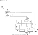
- FIG. 1 is a cross-sectional view of a jig module 100 for a solid oxide fuel cell according to an exemplary embodiment of the present invention.
- the jig module 100 for a solid oxide fuel cell according to an exemplary embodiment of the present invention will be described in detail with reference to FIG. 1 .
- the jig module 100 for a solid oxide fuel cell includes an upper jig 10, a lower jig 20, and a press unit 30. Further, the upper jig 10 and the lower jig 20 may be formed to have a cylindrical shape, and the upper jig 10 and the lower jig 20 may be formed of metal or ceramic.
- the upper jig 10 may include an oxygen supply pipe 11 and an oxygen discharge pipe 12, and the lower jig 20 may include a hydrogen supply pipe 21 and a hydrogen discharge pipe 22.
- the oxygen supply pipe 11, the oxygen discharge pipe 12, the hydrogen supply pipe 21, and the hydrogen discharge pipe 22 may be formed of alumina and alumina may be formed of an alumina material having a high melting point obtained by oxidizing aluminum.
- a seating groove (not illustrated) in which any one of a sealant and a unit cell is located may be formed, and in order to evaluate gas leakage through a sealant and a performance of a unit cell, the seating groove is coupled to be fitted to the upper jig 10 to be sealed to form a sealed portion 23. Therefore, a size of the upper jig 10 may be smaller than a size of the lower jig 20 and may be equal to a size of the seating groove.
- One side of the oxygen supply pipe 11 and the other side of the oxygen discharge pipe 12 of the upper jig 10 may be downwardly configured to communicate with each other toward the sealed portion 23, and one side of the hydrogen supply pipe 21 and the other side of the hydrogen discharge pipe 22 of the lower jig 20 may be upwardly configured to communicate with each other toward the seating groove.
- the upper jig 10 and the lower jig 20 may serve as an evaluating unit which measures a current and a voltage output from the unit cell.
- the upper jig 10 serves as a positive electrode
- the lower jig 20 serves as a negative electrode to measure power consumption (W: watt) of the unit cell per unit area. Performance measurement of the unit cell will be described below with reference to FIG. 3 .
- the upper jig 10 and the low jig 20 may serve as an air electrode interconnector and a fuel electrode interconnector, in this case, a flow passage may be formed on a surface on which the upper jig 10 and the lower jig 20 are in contact with the unit cell.
- Valves 13 which control flow rates of oxygen and hydrogen may be provided at one end of each of the oxygen discharge pipe 21 and the hydrogen discharge pipe 22.
- oxygen and hydrogen are supplied through the oxygen supply pipe 11 and the hydrogen supply pipe 21, it is possible to prevent the supplied oxygen and hydrogen from being leaked to the outside, by closing the valves 13 and when gas leakage through the sealant is measured, it is possible to measure amounts of oxygen and hydrogen leaked through the sealant by opening the valves 13.
- the jig module 100 may further include a measuring unit 50, and when the sealant is located in the seating groove, the measuring unit 50 is connected to the upper jig 10, the lower jig 20, and the valves to measure whether gas is leaked through the sealant and attachment strength of the sealant. Further, when the unit cell is located in the seating groove, the measuring unit 50 is connected to the upper jig 10 and the lower jig 20 to evaluate a performance of the unit cell. Methods for measuring whether the gas is leaked through the sealant and the attachment strength of the sealant, and evaluating a performance of the unit cell will be described below with reference to FIGS. 2 and 3 .
- the press unit 30 is disposed at one side of each of the upper jig 10 and the lower jig 20, and may serve to move the upper jig 10 and the lower jig 20. For example, in order to measure attachment strength of the sealant, the press unit 30 which is attached to the upper jig 10 upwardly pulls the upper jig 10 and the press unit 30 which is attached to the lower jig 20 downwardly pulls the lower jig 20 to stretch the sealant.
- the press units 30 may bring the sealant and the unit cell into close contact with the upper jig 10 and the lower jig 20 and pressurize the upper jig 10 and the lower jig 20 to seal the sealed portion 23.
- the press units 30 are attached to the upper jig 10 and the lower jig 20, respectively, so that the performance of the sealant and the performance of the unit cell may be simultaneously measured, and as a result, there is no need to replace an evaluating jig in accordance with a measurement purpose, so that economic effect is achieved.
- the jig module 100 for a solid oxide fuel cell according to the present invention may further include a control unit 40 which controls any one or more of a vertical movement of the press unit 30, a flow rate of oxygen which flows into the oxygen supply pipe 11, and a flow rate of hydrogen which flows into the hydrogen supply pipe 21.
- the control unit is connected to the press unit 30 to measure attachment strength of the sealant, and is connected to the valve located at one end of each of the oxygen discharge pipe 12 and the hydrogen discharge pipe 22 to measure a leakage amount of the oxygen and hydrogen, which are leaked through the sealant, and determine the performance of the sealant.
- control unit is connected to the upper jig 10 and the lower jig 20 to adjust an amount of a current applied to the unit cell and the fuel cell, and is connected to the measuring unit 50 to measure voltages of the air electrode and the fuel electrode due to the applied current to measure performances of the unit cell and the fuel cell.
- the control unit may control the bonding member to be off to separate the upper jig 10 and the lower jig 20 from each other, and when an amount of gas leaked through the sealant and the performance of the unit cell are measured, the control unit may control the bonding member to be on to seal the sealed portion 23.
- control unit 40 uses an existing publicly-known technology, a detailed description thereof will be omitted.
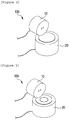
- FIG. 2 is a photograph illustrating the jig module 100 for a solid oxide fuel cell where a sealant is located in a seating groove.
- the jig module 100 for a solid oxide fuel cell according to the present invention may measure the attachment strength of the sealant and whether the gas is leaked, only using the sealant.
- the upper jig 10 is covered to form a sealed portion, and the upper jig 10 and the lower jig 20 are vertically stretched using the press unit to measure the attachment strength of the sealant.
- the upper jig 10 is covered to form a sealed portion, and the sealant and the upper jig 10 and the lower jig 20 are brought into close contact with each other using the press unit to remove an empty space from the sealed portion.
- the upper jig 10 and the lower jig 20 are brought into close contact with each other using a bonding member formed at a side of the sealed portion to seal the sealed portion.
- the bonding member may prevent air and hydrogen from being leaked to the outside and prevent outside gas from flowing into the sealed portion while the air and hydrogen pass through the sealant, but it should be noted that the sealed portion may be sealed by coupling the upper jig 10 to be fitted into the seating groove and the sealant located in the seating groove, so that the bonding member may be omitted.
- gas is supplied to the sealed portion through the oxygen supply pipe and the hydrogen supply pipe to measure whether gas is leaked through the sealant.
- the valves located at one end of each of the oxygen discharge pipe and the hydrogen discharge pipe are connected to the measuring unit, it is possible to determine whether gas is leaked through the sealant by opening the valves.
- the experiment for determining whether the gas is leaked through the sealant may be performed at a temperature of 400°C to 1,100°C.
- a composition and sealants having different properties are located in the jig module 100 for a solid oxide fuel cell and put in an electric furnace at a temperature of 400°C to 1,100°C to perform an experiment for a sealant gas leakage rate. Therefore, the gas leakage rate experiment is available without the configurations of the solid oxide fuel cell other than the sealant, and as a result, the experiment steps are simplified, and performances of one or more sealants are simultaneously measured, thereby shortening a time therefor.
- FIG. 3 is a photograph illustrating the jig module 100 for a solid oxide fuel cell where a unit cell is located in a seating groove.
- the unit cell is located in the seating groove, and the sealant is located around the unit cell, so that the upper jig 10 is fixed into the seating groove and the sealed portion is sealed.
- the upper jig 10 and the lower jig 20 may serve as an evaluating unit which is in contact with an air electrode and a fuel electrode of the unit cell to measure any one or more of a current, a voltage, and power consumption which are output to the unit cell.
- oxygen when oxygen is supplied to the air electrode through the oxygen supply pipe, oxygen receives electrons from the outside to be reduced to an oxygen ion, and when hydrogen is supplied to the fuel electrode through the hydrogen supply pipe, hydrogen is oxidized so that electrons are discharged through an external circuit, and as a result, the electrons flow from the fuel electrode to the air electrode to produce direct electricity and the upper jig 10 is in contact with the air electrode and the lower jig 20 is in contact with the fuel electrode, thereby detecting current/voltage which flows through the unit cell. Data on the detected current and voltage moves to the measuring unit to evaluate power consumption of the unit cell per unit area.
- the upper jig 10 and the lower jig 20 may further include a current/voltage detecting unit (not illustrated) which is in contact with an air electrode and a fuel electrode of the unit cell to measure any one or more of a current and a voltage which are output to the unit cell.
- a current/voltage detecting unit (not illustrated) which is in contact with an air electrode and a fuel electrode of the unit cell to measure any one or more of a current and a voltage which are output to the unit cell.
- the detecting unit When the detecting unit is formed in the upper jig 10, the detecting unit may downwardly protrude, and when the detecting unit is formed in the lower jig 20, the detecting unit may be formed to upwardly protrude.
- the detecting unit formed in the upper jig 10 is in contact with the air electrode, and the detecting unit formed in the lower jig 20 is in contact with the fuel electrode, thereby detecting the current and the voltage of the unit cell.
- the detecting unit may be formed of a single wire or a pair of wires may be formed to have a probe shape, and for example, one side of the detecting unit, which is in contact with the air electrode, discharges the current, and the other side of the detecting unit is applied with current, which is re-discharged from the air electrode, thereby measuring the voltage of the air electrode.
- the current and the voltage of the fuel electrode may be measured by the same manner.
Landscapes
- Life Sciences & Earth Sciences (AREA)
- Engineering & Computer Science (AREA)
- Manufacturing & Machinery (AREA)
- Sustainable Development (AREA)
- Sustainable Energy (AREA)
- Chemical & Material Sciences (AREA)
- Chemical Kinetics & Catalysis (AREA)
- Electrochemistry (AREA)
- General Chemical & Material Sciences (AREA)
- Fuel Cell (AREA)
Claims (5)
- Aufspannmodul (100) für eine Festoxid-Brennstoffzelle, wobei das Aufspannmodul umfasst:eine obere Aufspannung (10), die eine Sauerstoff-Zulaufleitung (11) und eine Sauerstoff-Ablaufleitung (12) einschließt,eine untere Aufspannung (20), welche einschließt: eine Sitzvertiefung; eine Wasserstoff-Zulaufleitung (21), von der eine Seite an die Sitzvertiefung angeschlossen ist; und eine Wasserstoff-Ablaufleitung (22), deren andere Seite an die Sitzvertiefung angeschlossen ist;wobei die obere Aufspannung (10) gekoppelt ist, um so in die Sitzvertiefung eingepasst zu werden, dass ein abgedichteter Abschnitt (23) gebildet wird, wobei die obere Aufspannung (10) derart ausgelegt ist, dass eine Seite der Sauerstoff-Zulaufleitung (11) und eine Seite der Sauerstoff-Ablaufleitung (12) zum abgedichteten Abschnitt (23) hin miteinander kommunizieren, dadurch gekennzeichnet, dass:das Aufspannmodul weiter umfasst:eine Presseneinheit (30), die die obere Aufspannung (10) und die untere Aufspannung (20) in einer vertikalen Richtung bewegt, undeine Steuereinheit (40), die ein beliebiges oder mehrere aus einer vertikalen Bewegung der Presseneinheit (30); einer Strömungsrate von Sauerstoff, der in die Sauerstoff-Zulaufleitung (11) strömt, und einer Strömungsrate von Wasserstoff, der in die Wasserstoff-Zulaufleitung (21) strömt, steuert.
- Aufspannmodul nach Anspruch 1, wobei die obere Aufspannung (10) und die untere Aufspannung (20) zylindrische Formen aufweisen.
- Aufspannmodul nach Anspruch 1, wobei an einem Ende von jeder aus der Wasserstoff-Ablaufleitung (22) und der Sauerstoff-Ablaufleitung (12) Ventile (13) bereitgestellt sind, die Sauerstoff- und Wasserstoff-Strömungsraten steuern.
- Aufspannmodul nach Anspruch 1, weiter umfassend:
eine Messeinheit (50), die, wenn sich ein Dichtmittel in der Sitzvertiefung befindet, misst, ob das Gas durch das Dichtmittel entweicht, und Befestigungsstärke des Dichtmittels misst. - Aufspannmodul nach Anspruch 1, weiter umfassend:
eine Messeinheit (50), die, wenn sich eine Einheitszelle in der Sitzvertiefung befindet, eine Leistung der Einheitszelle beurteilt.
Applications Claiming Priority (2)
| Application Number | Priority Date | Filing Date | Title |
|---|---|---|---|
| KR1020160108529A KR102089828B1 (ko) | 2016-08-25 | 2016-08-25 | 고체 산화물 연료전지용 지그 모듈 |
| PCT/KR2017/009256 WO2018038550A1 (ko) | 2016-08-25 | 2017-08-24 | 고체 산화물 연료전지용 지그 모듈 |
Publications (3)
| Publication Number | Publication Date |
|---|---|
| EP3364485A1 EP3364485A1 (de) | 2018-08-22 |
| EP3364485A4 EP3364485A4 (de) | 2018-11-14 |
| EP3364485B1 true EP3364485B1 (de) | 2021-01-13 |
Family
ID=61246191
Family Applications (1)
| Application Number | Title | Priority Date | Filing Date |
|---|---|---|---|
| EP17843970.9A Active EP3364485B1 (de) | 2016-08-25 | 2017-08-24 | Aufspannmodul für festoxid-brennstoffzelle |
Country Status (6)
| Country | Link |
|---|---|
| US (1) | US10673080B2 (de) |
| EP (1) | EP3364485B1 (de) |
| JP (1) | JP6766305B2 (de) |
| KR (1) | KR102089828B1 (de) |
| CN (1) | CN108352547B (de) |
| WO (1) | WO2018038550A1 (de) |
Families Citing this family (3)
| Publication number | Priority date | Publication date | Assignee | Title |
|---|---|---|---|---|
| KR20190105775A (ko) * | 2018-03-06 | 2019-09-18 | 주식회사 엘지화학 | 연료전지 스택의 성능 평가 장치 |
| KR102631551B1 (ko) * | 2019-02-01 | 2024-01-30 | 주식회사 엘지화학 | 비가압식의 연료전지 성능평가 장치 |
| KR102273283B1 (ko) | 2019-12-18 | 2021-07-05 | 인천대학교 산학협력단 | 고체산화물 연료전지의 성능 평가 장치 |
Family Cites Families (15)
| Publication number | Priority date | Publication date | Assignee | Title |
|---|---|---|---|---|
| JP3882675B2 (ja) | 2002-05-08 | 2007-02-21 | 株式会社島津製作所 | リーク検査装置および被試験体装着治具 |
| JP2005142062A (ja) * | 2003-11-07 | 2005-06-02 | Matsushita Electric Ind Co Ltd | 燃料電池の検査装置および検査方法 |
| JP2008077911A (ja) * | 2006-09-20 | 2008-04-03 | Nissan Motor Co Ltd | 燃料電池システム |
| DE102006058335A1 (de) * | 2006-12-11 | 2008-06-12 | Staxera Gmbh | Brennstoffzellenstapel und Dichtung für einen Brennstoffzellenstapel sowie deren Herstellungsverfahren |
| JP2009110908A (ja) | 2007-11-01 | 2009-05-21 | Honda Motor Co Ltd | 燃料電池のリーク検査方法及び装置 |
| JP2009252561A (ja) | 2008-04-07 | 2009-10-29 | Honda Motor Co Ltd | 試験装置 |
| JP5439081B2 (ja) | 2008-10-21 | 2014-03-12 | 日本碍子株式会社 | 構造体および特性測定装置 |
| KR101154224B1 (ko) * | 2009-03-11 | 2012-06-18 | 주식회사 리빙케어 | 일체형 연료전지 기체확산층 물성 평가 장치 |
| FR2959565B1 (fr) | 2010-04-28 | 2012-06-08 | Commissariat Energie Atomique | Procede de test d'etancheite non-destructif d'un electrolyte de cellule electrochimique |
| CN103698706A (zh) * | 2012-09-27 | 2014-04-02 | 中国科学院上海硅酸盐研究所 | 大面积平板型固体氧化物燃料电池电流分布的测量方法及装置 |
| KR101408700B1 (ko) | 2013-05-31 | 2014-06-17 | 한국세라믹기술원 | 고체전해질 연료전지의 특성측정용 지그 |
| KR101490747B1 (ko) * | 2013-06-14 | 2015-02-06 | 주식회사휴비스 | 연료전지 성능 평가 장치의 항온 항압 가스 공급 장치 |
| KR101540514B1 (ko) * | 2013-08-01 | 2015-07-29 | 주식회사 엘지화학 | 고체산화물 연료전지 셀 전압 측정 장치 |
| KR101585454B1 (ko) * | 2013-11-13 | 2016-01-21 | 재단법인 포항산업과학연구원 | 연료전지 시험평가장치 |
| JP2015185320A (ja) * | 2014-03-24 | 2015-10-22 | アイシン精機株式会社 | 燃料電池セルの特性評価方法、燃料電池装置、及び燃料電池セルの製造方法 |
-
2016
- 2016-08-25 KR KR1020160108529A patent/KR102089828B1/ko active Active
-
2017
- 2017-08-24 EP EP17843970.9A patent/EP3364485B1/de active Active
- 2017-08-24 WO PCT/KR2017/009256 patent/WO2018038550A1/ko not_active Ceased
- 2017-08-24 CN CN201780004044.3A patent/CN108352547B/zh active Active
- 2017-08-24 US US15/772,896 patent/US10673080B2/en active Active
- 2017-08-24 JP JP2018520158A patent/JP6766305B2/ja active Active
Non-Patent Citations (1)
| Title |
|---|
| None * |
Also Published As
| Publication number | Publication date |
|---|---|
| EP3364485A4 (de) | 2018-11-14 |
| JP2018536254A (ja) | 2018-12-06 |
| US10673080B2 (en) | 2020-06-02 |
| CN108352547B (zh) | 2021-07-09 |
| CN108352547A (zh) | 2018-07-31 |
| WO2018038550A1 (ko) | 2018-03-01 |
| KR102089828B1 (ko) | 2020-04-23 |
| US20180316025A1 (en) | 2018-11-01 |
| JP6766305B2 (ja) | 2020-10-14 |
| KR20180023358A (ko) | 2018-03-07 |
| EP3364485A1 (de) | 2018-08-22 |
Similar Documents
| Publication | Publication Date | Title |
|---|---|---|
| US6068942A (en) | Process for operating a PEM fuel cell installation | |
| CN112068019B (zh) | 一种平板型sofc电流密度分布式端板测试结构及测试方法 | |
| EP3364485B1 (de) | Aufspannmodul für festoxid-brennstoffzelle | |
| EP2950376B1 (de) | Brennstoffzellen-system und fahrzeug mit brennstoffzellenantrieb | |
| JP2013054925A (ja) | 燃料電池の検査方法および検査装置 | |
| CN101855763A (zh) | 燃料电池系统和该系统的氢泄漏判断方法 | |
| US9373854B2 (en) | Solid polymer fuel cell | |
| KR20100102358A (ko) | 일체형 연료전지 기체확산층 물성 평가 장치 | |
| JPWO2018155112A1 (ja) | 電気化学反応単位および電気化学反応セルスタック | |
| CN110297187B (zh) | 燃料电池的电流泄漏检查方法 | |
| JP2009021099A (ja) | 燃料電池スタック | |
| JP2019169240A (ja) | 電気化学反応セルスタックの運転方法および電気化学反応システム | |
| KR100534770B1 (ko) | 연료 전지 스택용 셀 전압 측정장치 | |
| KR101405374B1 (ko) | 연료 전지 | |
| US10529998B2 (en) | Fuel cell stack, and method of determining maintenance time of fuel cell stack | |
| KR101105050B1 (ko) | 연료전지 스택 | |
| KR101540514B1 (ko) | 고체산화물 연료전지 셀 전압 측정 장치 | |
| KR101113642B1 (ko) | 연료전지용 전극막 어셈블리 사전 검수 장치 및 방법 | |
| KR101333935B1 (ko) | 연료전지 단위 팩 및 이를 포함하는 카세트형 연료전지 | |
| JP2005302320A (ja) | 燃料電池の検査方法 | |
| JP2010113863A (ja) | 燃料電池 | |
| JP2005322534A (ja) | 高分子電解質型燃料電池の試験方法及び高分子電解質型燃料電池 | |
| JP2023078854A (ja) | セル評価用ホルダ | |
| KR20080113942A (ko) | 연료전지 분리판의 접착부 기밀구조 | |
| JP7294881B2 (ja) | 電気化学セル評価用ホルダ及びセル評価システム |
Legal Events
| Date | Code | Title | Description |
|---|---|---|---|
| STAA | Information on the status of an ep patent application or granted ep patent |
Free format text: STATUS: THE INTERNATIONAL PUBLICATION HAS BEEN MADE |
|
| PUAI | Public reference made under article 153(3) epc to a published international application that has entered the european phase |
Free format text: ORIGINAL CODE: 0009012 |
|
| STAA | Information on the status of an ep patent application or granted ep patent |
Free format text: STATUS: REQUEST FOR EXAMINATION WAS MADE |
|
| 17P | Request for examination filed |
Effective date: 20180503 |
|
| AK | Designated contracting states |
Kind code of ref document: A1 Designated state(s): AL AT BE BG CH CY CZ DE DK EE ES FI FR GB GR HR HU IE IS IT LI LT LU LV MC MK MT NL NO PL PT RO RS SE SI SK SM TR |
|
| AX | Request for extension of the european patent |
Extension state: BA ME |
|
| RIC1 | Information provided on ipc code assigned before grant |
Ipc: H01M 8/0273 20160101ALI20180922BHEP Ipc: H01M 8/12 20160101AFI20180922BHEP Ipc: H01M 8/00 20160101ALI20180922BHEP Ipc: H01M 8/124 20160101ALI20180922BHEP Ipc: H01M 8/04298 20160101ALI20180922BHEP |
|
| A4 | Supplementary search report drawn up and despatched |
Effective date: 20181011 |
|
| STAA | Information on the status of an ep patent application or granted ep patent |
Free format text: STATUS: EXAMINATION IS IN PROGRESS |
|
| 17Q | First examination report despatched |
Effective date: 20190925 |
|
| DAV | Request for validation of the european patent (deleted) | ||
| DAX | Request for extension of the european patent (deleted) | ||
| GRAP | Despatch of communication of intention to grant a patent |
Free format text: ORIGINAL CODE: EPIDOSNIGR1 |
|
| STAA | Information on the status of an ep patent application or granted ep patent |
Free format text: STATUS: GRANT OF PATENT IS INTENDED |
|
| INTG | Intention to grant announced |
Effective date: 20201013 |
|
| GRAS | Grant fee paid |
Free format text: ORIGINAL CODE: EPIDOSNIGR3 |
|
| GRAA | (expected) grant |
Free format text: ORIGINAL CODE: 0009210 |
|
| STAA | Information on the status of an ep patent application or granted ep patent |
Free format text: STATUS: THE PATENT HAS BEEN GRANTED |
|
| AK | Designated contracting states |
Kind code of ref document: B1 Designated state(s): AL AT BE BG CH CY CZ DE DK EE ES FI FR GB GR HR HU IE IS IT LI LT LU LV MC MK MT NL NO PL PT RO RS SE SI SK SM TR |
|
| REG | Reference to a national code |
Ref country code: GB Ref legal event code: FG4D |
|
| REG | Reference to a national code |
Ref country code: CH Ref legal event code: EP |
|
| REG | Reference to a national code |
Ref country code: IE Ref legal event code: FG4D |
|
| REG | Reference to a national code |
Ref country code: DE Ref legal event code: R096 Ref document number: 602017031503 Country of ref document: DE |
|
| REG | Reference to a national code |
Ref country code: AT Ref legal event code: REF Ref document number: 1355233 Country of ref document: AT Kind code of ref document: T Effective date: 20210215 |
|
| REG | Reference to a national code |
Ref country code: AT Ref legal event code: MK05 Ref document number: 1355233 Country of ref document: AT Kind code of ref document: T Effective date: 20210113 |
|
| REG | Reference to a national code |
Ref country code: NL Ref legal event code: MP Effective date: 20210113 |
|
| REG | Reference to a national code |
Ref country code: LT Ref legal event code: MG9D |
|
| PG25 | Lapsed in a contracting state [announced via postgrant information from national office to epo] |
Ref country code: BG Free format text: LAPSE BECAUSE OF FAILURE TO SUBMIT A TRANSLATION OF THE DESCRIPTION OR TO PAY THE FEE WITHIN THE PRESCRIBED TIME-LIMIT Effective date: 20210413 Ref country code: LT Free format text: LAPSE BECAUSE OF FAILURE TO SUBMIT A TRANSLATION OF THE DESCRIPTION OR TO PAY THE FEE WITHIN THE PRESCRIBED TIME-LIMIT Effective date: 20210113 Ref country code: NO Free format text: LAPSE BECAUSE OF FAILURE TO SUBMIT A TRANSLATION OF THE DESCRIPTION OR TO PAY THE FEE WITHIN THE PRESCRIBED TIME-LIMIT Effective date: 20210413 Ref country code: PT Free format text: LAPSE BECAUSE OF FAILURE TO SUBMIT A TRANSLATION OF THE DESCRIPTION OR TO PAY THE FEE WITHIN THE PRESCRIBED TIME-LIMIT Effective date: 20210513 Ref country code: HR Free format text: LAPSE BECAUSE OF FAILURE TO SUBMIT A TRANSLATION OF THE DESCRIPTION OR TO PAY THE FEE WITHIN THE PRESCRIBED TIME-LIMIT Effective date: 20210113 Ref country code: FI Free format text: LAPSE BECAUSE OF FAILURE TO SUBMIT A TRANSLATION OF THE DESCRIPTION OR TO PAY THE FEE WITHIN THE PRESCRIBED TIME-LIMIT Effective date: 20210113 Ref country code: GR Free format text: LAPSE BECAUSE OF FAILURE TO SUBMIT A TRANSLATION OF THE DESCRIPTION OR TO PAY THE FEE WITHIN THE PRESCRIBED TIME-LIMIT Effective date: 20210414 |
|
| PG25 | Lapsed in a contracting state [announced via postgrant information from national office to epo] |
Ref country code: SE Free format text: LAPSE BECAUSE OF FAILURE TO SUBMIT A TRANSLATION OF THE DESCRIPTION OR TO PAY THE FEE WITHIN THE PRESCRIBED TIME-LIMIT Effective date: 20210113 Ref country code: RS Free format text: LAPSE BECAUSE OF FAILURE TO SUBMIT A TRANSLATION OF THE DESCRIPTION OR TO PAY THE FEE WITHIN THE PRESCRIBED TIME-LIMIT Effective date: 20210113 Ref country code: PL Free format text: LAPSE BECAUSE OF FAILURE TO SUBMIT A TRANSLATION OF THE DESCRIPTION OR TO PAY THE FEE WITHIN THE PRESCRIBED TIME-LIMIT Effective date: 20210113 Ref country code: LV Free format text: LAPSE BECAUSE OF FAILURE TO SUBMIT A TRANSLATION OF THE DESCRIPTION OR TO PAY THE FEE WITHIN THE PRESCRIBED TIME-LIMIT Effective date: 20210113 Ref country code: AT Free format text: LAPSE BECAUSE OF FAILURE TO SUBMIT A TRANSLATION OF THE DESCRIPTION OR TO PAY THE FEE WITHIN THE PRESCRIBED TIME-LIMIT Effective date: 20210113 |
|
| PG25 | Lapsed in a contracting state [announced via postgrant information from national office to epo] |
Ref country code: IS Free format text: LAPSE BECAUSE OF FAILURE TO SUBMIT A TRANSLATION OF THE DESCRIPTION OR TO PAY THE FEE WITHIN THE PRESCRIBED TIME-LIMIT Effective date: 20210513 |
|
| REG | Reference to a national code |
Ref country code: DE Ref legal event code: R097 Ref document number: 602017031503 Country of ref document: DE |
|
| PG25 | Lapsed in a contracting state [announced via postgrant information from national office to epo] |
Ref country code: SM Free format text: LAPSE BECAUSE OF FAILURE TO SUBMIT A TRANSLATION OF THE DESCRIPTION OR TO PAY THE FEE WITHIN THE PRESCRIBED TIME-LIMIT Effective date: 20210113 Ref country code: CZ Free format text: LAPSE BECAUSE OF FAILURE TO SUBMIT A TRANSLATION OF THE DESCRIPTION OR TO PAY THE FEE WITHIN THE PRESCRIBED TIME-LIMIT Effective date: 20210113 Ref country code: EE Free format text: LAPSE BECAUSE OF FAILURE TO SUBMIT A TRANSLATION OF THE DESCRIPTION OR TO PAY THE FEE WITHIN THE PRESCRIBED TIME-LIMIT Effective date: 20210113 |
|
| PLBE | No opposition filed within time limit |
Free format text: ORIGINAL CODE: 0009261 |
|
| STAA | Information on the status of an ep patent application or granted ep patent |
Free format text: STATUS: NO OPPOSITION FILED WITHIN TIME LIMIT |
|
| PG25 | Lapsed in a contracting state [announced via postgrant information from national office to epo] |
Ref country code: DK Free format text: LAPSE BECAUSE OF FAILURE TO SUBMIT A TRANSLATION OF THE DESCRIPTION OR TO PAY THE FEE WITHIN THE PRESCRIBED TIME-LIMIT Effective date: 20210113 Ref country code: SK Free format text: LAPSE BECAUSE OF FAILURE TO SUBMIT A TRANSLATION OF THE DESCRIPTION OR TO PAY THE FEE WITHIN THE PRESCRIBED TIME-LIMIT Effective date: 20210113 Ref country code: RO Free format text: LAPSE BECAUSE OF FAILURE TO SUBMIT A TRANSLATION OF THE DESCRIPTION OR TO PAY THE FEE WITHIN THE PRESCRIBED TIME-LIMIT Effective date: 20210113 |
|
| 26N | No opposition filed |
Effective date: 20211014 |
|
| PG25 | Lapsed in a contracting state [announced via postgrant information from national office to epo] |
Ref country code: ES Free format text: LAPSE BECAUSE OF FAILURE TO SUBMIT A TRANSLATION OF THE DESCRIPTION OR TO PAY THE FEE WITHIN THE PRESCRIBED TIME-LIMIT Effective date: 20210113 Ref country code: AL Free format text: LAPSE BECAUSE OF FAILURE TO SUBMIT A TRANSLATION OF THE DESCRIPTION OR TO PAY THE FEE WITHIN THE PRESCRIBED TIME-LIMIT Effective date: 20210113 |
|
| PG25 | Lapsed in a contracting state [announced via postgrant information from national office to epo] |
Ref country code: SI Free format text: LAPSE BECAUSE OF FAILURE TO SUBMIT A TRANSLATION OF THE DESCRIPTION OR TO PAY THE FEE WITHIN THE PRESCRIBED TIME-LIMIT Effective date: 20210113 |
|
| REG | Reference to a national code |
Ref country code: CH Ref legal event code: PL |
|
| PG25 | Lapsed in a contracting state [announced via postgrant information from national office to epo] |
Ref country code: MC Free format text: LAPSE BECAUSE OF FAILURE TO SUBMIT A TRANSLATION OF THE DESCRIPTION OR TO PAY THE FEE WITHIN THE PRESCRIBED TIME-LIMIT Effective date: 20210113 |
|
| REG | Reference to a national code |
Ref country code: BE Ref legal event code: MM Effective date: 20210831 |
|
| PG25 | Lapsed in a contracting state [announced via postgrant information from national office to epo] |
Ref country code: LI Free format text: LAPSE BECAUSE OF NON-PAYMENT OF DUE FEES Effective date: 20210831 Ref country code: IT Free format text: LAPSE BECAUSE OF FAILURE TO SUBMIT A TRANSLATION OF THE DESCRIPTION OR TO PAY THE FEE WITHIN THE PRESCRIBED TIME-LIMIT Effective date: 20210113 Ref country code: CH Free format text: LAPSE BECAUSE OF NON-PAYMENT OF DUE FEES Effective date: 20210831 |
|
| PG25 | Lapsed in a contracting state [announced via postgrant information from national office to epo] |
Ref country code: IS Free format text: LAPSE BECAUSE OF FAILURE TO SUBMIT A TRANSLATION OF THE DESCRIPTION OR TO PAY THE FEE WITHIN THE PRESCRIBED TIME-LIMIT Effective date: 20210513 Ref country code: LU Free format text: LAPSE BECAUSE OF NON-PAYMENT OF DUE FEES Effective date: 20210824 |
|
| PG25 | Lapsed in a contracting state [announced via postgrant information from national office to epo] |
Ref country code: IE Free format text: LAPSE BECAUSE OF NON-PAYMENT OF DUE FEES Effective date: 20210824 Ref country code: BE Free format text: LAPSE BECAUSE OF NON-PAYMENT OF DUE FEES Effective date: 20210831 |
|
| PG25 | Lapsed in a contracting state [announced via postgrant information from national office to epo] |
Ref country code: NL Free format text: LAPSE BECAUSE OF NON-PAYMENT OF DUE FEES Effective date: 20210113 Ref country code: CY Free format text: LAPSE BECAUSE OF FAILURE TO SUBMIT A TRANSLATION OF THE DESCRIPTION OR TO PAY THE FEE WITHIN THE PRESCRIBED TIME-LIMIT Effective date: 20210113 |
|
| PG25 | Lapsed in a contracting state [announced via postgrant information from national office to epo] |
Ref country code: HU Free format text: LAPSE BECAUSE OF FAILURE TO SUBMIT A TRANSLATION OF THE DESCRIPTION OR TO PAY THE FEE WITHIN THE PRESCRIBED TIME-LIMIT; INVALID AB INITIO Effective date: 20170824 |
|
| PG25 | Lapsed in a contracting state [announced via postgrant information from national office to epo] |
Ref country code: MK Free format text: LAPSE BECAUSE OF FAILURE TO SUBMIT A TRANSLATION OF THE DESCRIPTION OR TO PAY THE FEE WITHIN THE PRESCRIBED TIME-LIMIT Effective date: 20210113 |
|
| PG25 | Lapsed in a contracting state [announced via postgrant information from national office to epo] |
Ref country code: MT Free format text: LAPSE BECAUSE OF FAILURE TO SUBMIT A TRANSLATION OF THE DESCRIPTION OR TO PAY THE FEE WITHIN THE PRESCRIBED TIME-LIMIT Effective date: 20210113 |
|
| PGFP | Annual fee paid to national office [announced via postgrant information from national office to epo] |
Ref country code: DE Payment date: 20250721 Year of fee payment: 9 |
|
| PGFP | Annual fee paid to national office [announced via postgrant information from national office to epo] |
Ref country code: GB Payment date: 20250722 Year of fee payment: 9 |
|
| PGFP | Annual fee paid to national office [announced via postgrant information from national office to epo] |
Ref country code: FR Payment date: 20250725 Year of fee payment: 9 |
|
| PG25 | Lapsed in a contracting state [announced via postgrant information from national office to epo] |
Ref country code: TR Free format text: LAPSE BECAUSE OF FAILURE TO SUBMIT A TRANSLATION OF THE DESCRIPTION OR TO PAY THE FEE WITHIN THE PRESCRIBED TIME-LIMIT Effective date: 20210113 |