EP3364015B1 - Elektromagnetisches schaltventil und kraftstoffhochdruckpumpe - Google Patents
Elektromagnetisches schaltventil und kraftstoffhochdruckpumpe Download PDFInfo
- Publication number
- EP3364015B1 EP3364015B1 EP17156169.9A EP17156169A EP3364015B1 EP 3364015 B1 EP3364015 B1 EP 3364015B1 EP 17156169 A EP17156169 A EP 17156169A EP 3364015 B1 EP3364015 B1 EP 3364015B1
- Authority
- EP
- European Patent Office
- Prior art keywords
- armature
- pole piece
- switching valve
- outer periphery
- region
- Prior art date
- Legal status (The legal status is an assumption and is not a legal conclusion. Google has not performed a legal analysis and makes no representation as to the accuracy of the status listed.)
- Active
Links
- 239000000446 fuel Substances 0.000 title claims description 40
- 230000004907 flux Effects 0.000 claims description 27
- 238000002485 combustion reaction Methods 0.000 claims description 19
- 238000002347 injection Methods 0.000 claims description 13
- 239000007924 injection Substances 0.000 claims description 13
- 229920006395 saturated elastomer Polymers 0.000 claims 1
- 238000010586 diagram Methods 0.000 description 6
- 238000000034 method Methods 0.000 description 3
- 230000005284 excitation Effects 0.000 description 2
- 238000004804 winding Methods 0.000 description 2
- 241001295925 Gegenes Species 0.000 description 1
- 230000001133 acceleration Effects 0.000 description 1
- 230000003213 activating effect Effects 0.000 description 1
- 239000012141 concentrate Substances 0.000 description 1
- 230000001419 dependent effect Effects 0.000 description 1
- 230000000694 effects Effects 0.000 description 1
- 239000002184 metal Substances 0.000 description 1
Images


Classifications
-
- F—MECHANICAL ENGINEERING; LIGHTING; HEATING; WEAPONS; BLASTING
- F02—COMBUSTION ENGINES; HOT-GAS OR COMBUSTION-PRODUCT ENGINE PLANTS
- F02M—SUPPLYING COMBUSTION ENGINES IN GENERAL WITH COMBUSTIBLE MIXTURES OR CONSTITUENTS THEREOF
- F02M51/00—Fuel-injection apparatus characterised by being operated electrically
- F02M51/06—Injectors peculiar thereto with means directly operating the valve needle
- F02M51/061—Injectors peculiar thereto with means directly operating the valve needle using electromagnetic operating means
- F02M51/0625—Injectors peculiar thereto with means directly operating the valve needle using electromagnetic operating means characterised by arrangement of mobile armatures
- F02M51/0664—Injectors peculiar thereto with means directly operating the valve needle using electromagnetic operating means characterised by arrangement of mobile armatures having a cylindrically or partly cylindrically shaped armature, e.g. entering the winding; having a plate-shaped or undulated armature entering the winding
-
- F—MECHANICAL ENGINEERING; LIGHTING; HEATING; WEAPONS; BLASTING
- F02—COMBUSTION ENGINES; HOT-GAS OR COMBUSTION-PRODUCT ENGINE PLANTS
- F02M—SUPPLYING COMBUSTION ENGINES IN GENERAL WITH COMBUSTIBLE MIXTURES OR CONSTITUENTS THEREOF
- F02M59/00—Pumps specially adapted for fuel-injection and not provided for in groups F02M39/00 -F02M57/00, e.g. rotary cylinder-block type of pumps
- F02M59/20—Varying fuel delivery in quantity or timing
- F02M59/36—Varying fuel delivery in quantity or timing by variably-timed valves controlling fuel passages to pumping elements or overflow passages
- F02M59/366—Valves being actuated electrically
- F02M59/368—Pump inlet valves being closed when actuated
-
- F—MECHANICAL ENGINEERING; LIGHTING; HEATING; WEAPONS; BLASTING
- F02—COMBUSTION ENGINES; HOT-GAS OR COMBUSTION-PRODUCT ENGINE PLANTS
- F02M—SUPPLYING COMBUSTION ENGINES IN GENERAL WITH COMBUSTIBLE MIXTURES OR CONSTITUENTS THEREOF
- F02M51/00—Fuel-injection apparatus characterised by being operated electrically
- F02M51/06—Injectors peculiar thereto with means directly operating the valve needle
- F02M51/061—Injectors peculiar thereto with means directly operating the valve needle using electromagnetic operating means
-
- F—MECHANICAL ENGINEERING; LIGHTING; HEATING; WEAPONS; BLASTING
- F02—COMBUSTION ENGINES; HOT-GAS OR COMBUSTION-PRODUCT ENGINE PLANTS
- F02D—CONTROLLING COMBUSTION ENGINES
- F02D41/00—Electrical control of supply of combustible mixture or its constituents
- F02D41/30—Controlling fuel injection
- F02D41/38—Controlling fuel injection of the high pressure type
- F02D41/3809—Common rail control systems
-
- F—MECHANICAL ENGINEERING; LIGHTING; HEATING; WEAPONS; BLASTING
- F02—COMBUSTION ENGINES; HOT-GAS OR COMBUSTION-PRODUCT ENGINE PLANTS
- F02M—SUPPLYING COMBUSTION ENGINES IN GENERAL WITH COMBUSTIBLE MIXTURES OR CONSTITUENTS THEREOF
- F02M51/00—Fuel-injection apparatus characterised by being operated electrically
- F02M51/06—Injectors peculiar thereto with means directly operating the valve needle
- F02M51/061—Injectors peculiar thereto with means directly operating the valve needle using electromagnetic operating means
- F02M51/0614—Injectors peculiar thereto with means directly operating the valve needle using electromagnetic operating means characterised by arrangement of electromagnets or fixed armature
-
- F—MECHANICAL ENGINEERING; LIGHTING; HEATING; WEAPONS; BLASTING
- F02—COMBUSTION ENGINES; HOT-GAS OR COMBUSTION-PRODUCT ENGINE PLANTS
- F02M—SUPPLYING COMBUSTION ENGINES IN GENERAL WITH COMBUSTIBLE MIXTURES OR CONSTITUENTS THEREOF
- F02M51/00—Fuel-injection apparatus characterised by being operated electrically
- F02M51/06—Injectors peculiar thereto with means directly operating the valve needle
- F02M51/061—Injectors peculiar thereto with means directly operating the valve needle using electromagnetic operating means
- F02M51/0625—Injectors peculiar thereto with means directly operating the valve needle using electromagnetic operating means characterised by arrangement of mobile armatures
- F02M51/0628—Injectors peculiar thereto with means directly operating the valve needle using electromagnetic operating means characterised by arrangement of mobile armatures having a stepped armature
-
- F—MECHANICAL ENGINEERING; LIGHTING; HEATING; WEAPONS; BLASTING
- F02—COMBUSTION ENGINES; HOT-GAS OR COMBUSTION-PRODUCT ENGINE PLANTS
- F02M—SUPPLYING COMBUSTION ENGINES IN GENERAL WITH COMBUSTIBLE MIXTURES OR CONSTITUENTS THEREOF
- F02M51/00—Fuel-injection apparatus characterised by being operated electrically
- F02M51/06—Injectors peculiar thereto with means directly operating the valve needle
- F02M51/061—Injectors peculiar thereto with means directly operating the valve needle using electromagnetic operating means
- F02M51/0625—Injectors peculiar thereto with means directly operating the valve needle using electromagnetic operating means characterised by arrangement of mobile armatures
- F02M51/0664—Injectors peculiar thereto with means directly operating the valve needle using electromagnetic operating means characterised by arrangement of mobile armatures having a cylindrically or partly cylindrically shaped armature, e.g. entering the winding; having a plate-shaped or undulated armature entering the winding
- F02M51/0671—Injectors peculiar thereto with means directly operating the valve needle using electromagnetic operating means characterised by arrangement of mobile armatures having a cylindrically or partly cylindrically shaped armature, e.g. entering the winding; having a plate-shaped or undulated armature entering the winding the armature having an elongated valve body attached thereto
- F02M51/0682—Injectors peculiar thereto with means directly operating the valve needle using electromagnetic operating means characterised by arrangement of mobile armatures having a cylindrically or partly cylindrically shaped armature, e.g. entering the winding; having a plate-shaped or undulated armature entering the winding the armature having an elongated valve body attached thereto the body being hollow and its interior communicating with the fuel flow
-
- F—MECHANICAL ENGINEERING; LIGHTING; HEATING; WEAPONS; BLASTING
- F02—COMBUSTION ENGINES; HOT-GAS OR COMBUSTION-PRODUCT ENGINE PLANTS
- F02M—SUPPLYING COMBUSTION ENGINES IN GENERAL WITH COMBUSTIBLE MIXTURES OR CONSTITUENTS THEREOF
- F02M59/00—Pumps specially adapted for fuel-injection and not provided for in groups F02M39/00 -F02M57/00, e.g. rotary cylinder-block type of pumps
- F02M59/20—Varying fuel delivery in quantity or timing
- F02M59/36—Varying fuel delivery in quantity or timing by variably-timed valves controlling fuel passages to pumping elements or overflow passages
- F02M59/366—Valves being actuated electrically
-
- F—MECHANICAL ENGINEERING; LIGHTING; HEATING; WEAPONS; BLASTING
- F02—COMBUSTION ENGINES; HOT-GAS OR COMBUSTION-PRODUCT ENGINE PLANTS
- F02M—SUPPLYING COMBUSTION ENGINES IN GENERAL WITH COMBUSTIBLE MIXTURES OR CONSTITUENTS THEREOF
- F02M59/00—Pumps specially adapted for fuel-injection and not provided for in groups F02M39/00 -F02M57/00, e.g. rotary cylinder-block type of pumps
- F02M59/44—Details, components parts, or accessories not provided for in, or of interest apart from, the apparatus of groups F02M59/02 - F02M59/42; Pumps having transducers, e.g. to measure displacement of pump rack or piston
- F02M59/46—Valves
- F02M59/466—Electrically operated valves, e.g. using electromagnetic or piezoelectric operating means
-
- F—MECHANICAL ENGINEERING; LIGHTING; HEATING; WEAPONS; BLASTING
- F02—COMBUSTION ENGINES; HOT-GAS OR COMBUSTION-PRODUCT ENGINE PLANTS
- F02M—SUPPLYING COMBUSTION ENGINES IN GENERAL WITH COMBUSTIBLE MIXTURES OR CONSTITUENTS THEREOF
- F02M63/00—Other fuel-injection apparatus having pertinent characteristics not provided for in groups F02M39/00 - F02M57/00 or F02M67/00; Details, component parts, or accessories of fuel-injection apparatus, not provided for in, or of interest apart from, the apparatus of groups F02M39/00 - F02M61/00 or F02M67/00; Combination of fuel pump with other devices, e.g. lubricating oil pump
- F02M63/0012—Valves
- F02M63/0014—Valves characterised by the valve actuating means
- F02M63/0015—Valves characterised by the valve actuating means electrical, e.g. using solenoid
- F02M63/0017—Valves characterised by the valve actuating means electrical, e.g. using solenoid using electromagnetic operating means
- F02M63/0021—Valves characterised by the valve actuating means electrical, e.g. using solenoid using electromagnetic operating means characterised by the arrangement of mobile armatures
- F02M63/0022—Valves characterised by the valve actuating means electrical, e.g. using solenoid using electromagnetic operating means characterised by the arrangement of mobile armatures the armature and the valve being allowed to move relatively to each other
-
- F—MECHANICAL ENGINEERING; LIGHTING; HEATING; WEAPONS; BLASTING
- F02—COMBUSTION ENGINES; HOT-GAS OR COMBUSTION-PRODUCT ENGINE PLANTS
- F02B—INTERNAL-COMBUSTION PISTON ENGINES; COMBUSTION ENGINES IN GENERAL
- F02B2275/00—Other engines, components or details, not provided for in other groups of this subclass
- F02B2275/14—Direct injection into combustion chamber
-
- F—MECHANICAL ENGINEERING; LIGHTING; HEATING; WEAPONS; BLASTING
- F02—COMBUSTION ENGINES; HOT-GAS OR COMBUSTION-PRODUCT ENGINE PLANTS
- F02M—SUPPLYING COMBUSTION ENGINES IN GENERAL WITH COMBUSTIBLE MIXTURES OR CONSTITUENTS THEREOF
- F02M2200/00—Details of fuel-injection apparatus, not otherwise provided for
- F02M2200/08—Fuel-injection apparatus having special means for influencing magnetic flux, e.g. for shielding or guiding magnetic flux
-
- F—MECHANICAL ENGINEERING; LIGHTING; HEATING; WEAPONS; BLASTING
- F02—COMBUSTION ENGINES; HOT-GAS OR COMBUSTION-PRODUCT ENGINE PLANTS
- F02M—SUPPLYING COMBUSTION ENGINES IN GENERAL WITH COMBUSTIBLE MIXTURES OR CONSTITUENTS THEREOF
- F02M2200/00—Details of fuel-injection apparatus, not otherwise provided for
- F02M2200/09—Fuel-injection apparatus having means for reducing noise
-
- H—ELECTRICITY
- H01—ELECTRIC ELEMENTS
- H01F—MAGNETS; INDUCTANCES; TRANSFORMERS; SELECTION OF MATERIALS FOR THEIR MAGNETIC PROPERTIES
- H01F7/00—Magnets
- H01F7/06—Electromagnets; Actuators including electromagnets
- H01F7/08—Electromagnets; Actuators including electromagnets with armatures
Definitions
- the invention relates to an electromagnetic switching valve for a fuel injection system of an internal combustion engine, and to a high-pressure fuel pump having such an electromagnetic switching valve.
- High-pressure fuel pumps in fuel injection systems in internal combustion engines are used to apply a high pressure to a fuel, the pressure being, for example, in gasoline internal combustion engines in the range from 150 bar to 400 bar and in diesel internal combustion engines in the range from 1500 bar to 2500 bar.
- valve arrangements can be provided at different positions on the path that the fuel takes from a tank to the respective combustion chamber, for example as an inlet valve or outlet valve on a high-pressure fuel pump that pressurizes the fuel, but also, for example, as a relief valve in various positions the fuel injection system, for example on a common rail, which stores the pressurized fuel before the injection into the combustion chamber.
- Fast switching solenoid valves are often used for volume flow and / or pressure control.
- a return spring holds a closing element a valve area of such an electromagnetic switching valve open or closed against a volume flow.
- the associated actuator area that is to say the magnetic actuator, which opens or closes the closing element, is designed in such a way that the return spring can overpress the actuator force of the magnetic actuator in a certain time, in order thus to switch the switching valve.
- Electromagnetic switching valves are known from DE 10 2014 214231 A1 , US 2007/176716 A1 , JP 2002 310029 A , DE 10 2009 054838 and US 2004/050978 A1 .
- the switching magnet has components separated by a force-generating air gap, namely a movable armature and a fixed pole core, which are kept apart by the return spring.
- a force-generating air gap namely a movable armature and a fixed pole core
- the switching magnet By activating a solenoid in the switching magnet by applying electric current, a magnetic field is built up in a winding of the solenoid.
- This magnetic field induces a magnetic flux in the surrounding metal components, in particular in the armature and the pole core, so that a magnetic force is built up between the armature and the pole core.
- a restoring force of the restoring spring is overcome by this magnetic force and the coupled hydraulics are controlled.
- the magnetic force drops and the restoring force controls the hydraulic system in the starting position. So far, the dynamics of the switching valve have been designed for the operating state in which the fastest switching characteristics are required during operation. However, this increases the momentum forces between the switching magnetic components, namely the armature and the pole core.
- the switching valve has so far been designed so that the highest possible magnetic flux density in the air gap between armature and pole core occurs at the operating point at which the maximum air gap between armature and pole core is present and at which a balance of forces between the return spring and the magnetic force of the solenoid is established is set so that the moving components are excited to move as quickly as possible. During the movement process, the moving components are then accelerated further by the magnetic force and the air gap is reduced. In the state of the minimum air gap, the magnetic force is then maximum.
- the impulse forces depend on the mass of the moving components and their speed. With high impulse forces, the consequence is that high wear can occur between the components and the noise level during operation is very high. Noise occurs every time the switching state changes, both from the solenoid itself and from the hydraulics. At least two components hit each other and thus generate noise.
- such a switching valve is used as a digital inlet valve on a high-pressure fuel pump in a fuel injection system of an internal combustion engine.
- the switching time of such an intake valve is designed so that it is able to switch quickly even at the highest engine speed of the internal combustion engine.
- this is in contrast to the goal that no significant noise should be generated in another operating state of the internal combustion engine, namely when the engine is idling.
- the switching valve was designed for the switching time for the operating point with the highest switching dynamics. Attempts have been made to reduce noise and wear for movements that are contrary the switching direction of the switching magnet are directed to intercept with short-term current pulses to increase the magnetic force. However, it is difficult to weaken movements in the switching direction of the switching valve.
- the object of the invention is therefore to provide an electromagnetic switching valve in which noise development can be reduced to a minimum in all operating points.
- a high-pressure fuel pump having such an electromagnetic switching valve is the subject of the independent claim.
- An electromagnetic switching valve for a fuel injection system of an internal combustion engine has a valve area with a closing element for closing the switching valve and an actuator area for moving the closing element along an axis of movement.
- the actuator region comprises an armature movable along the movement axis, which is coupled to the closing element for moving the closing element, a fixed pole piece and a solenoid for generating a magnetic flux in the armature and the pole piece.
- the armature has a magnetic flux concentration range in which a magnetic flux is saturable and which is formed in that an armature outer circumference has a shoulder, so that the armature has a smaller, first armature outer circumference and a larger, second armature outer circumference, the first armature outer circumference at most 3/4 of the second outer circumference of the anchor (U A2 ).
- the first outer circumference of the anchor is essentially half of a total length of the anchor along the movement axis.
- the armature and the pole piece are arranged adjacent to one another, the region of the armature with the first outer circumference of the armature being arranged facing the pole piece.
- the shoulder in the armature is arranged at a defined height and with a defined diameter and a defined length in order to be able to achieve a defined magnetic flux concentration in the armature.
- the constriction not only achieves a magnetic flux concentration in the armature, but also reduces the overall mass of the armature.
- the desired magnetic force is achieved faster than before, which is accompanied by a reduction in the switching time of the switching valve.
- the armature is not accelerated so much in the movement phase, although the speed still corresponds to that previously known. Overall, the total switching time is reduced and thus improved.
- An armature surface and a pole piece surface are preferably located directly opposite one another, the armature surface of the armature in the region of the first outer circumference of the armature being approximately half of the pole piece surface.
- the pole piece has a constriction in an outer pole piece circumference to form a magnetic flux concentration area.
- a magnetic flux concentration can also be achieved in the pole piece, which in turn leads to an improved switching time of the switching valve.
- the constriction is arranged in a half of the pole piece facing the armature, the constriction being in particular at least 1/5 of a total length of the pole piece along the axis of movement.
- the outer circumference of the pole piece is preferably reduced by at least 1/4 in the region of the constriction.
- the constriction is arranged at a defined height in the pole piece and with a defined diameter and a defined length in order to be able to achieve a defined magnetic flux concentration in the pole piece.
- the constriction of the pole piece along the movement axis is particularly advantageously located at the level of a spring recess of a return spring between the pole piece and the armature.
- the constriction along the axis of movement is also advantageously at the level of the solenoid.
- a high-pressure fuel pump for a fuel injection system of an internal combustion engine advantageously has an electromagnetic switching valve described above.
- the switching valve can be formed, for example, as an inlet valve for the high-pressure fuel pump or as an outlet valve. However, it is also possible to provide the switching valve described as a pressure control valve which is arranged, for example, on a common rail of a fuel injection system.
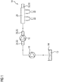
- Fig. 1 shows a schematic overview of a fuel injection system 10 of an internal combustion engine, which delivers a fuel 12 from a tank 14 via a prefeed pump 16, a high-pressure fuel pump 18 and a high-pressure fuel reservoir 20 to injectors 22, which then inject the fuel 12 into combustion chambers of the internal combustion engine.
- the fuel 12 is introduced into the high-pressure fuel pump 18 via an inlet valve 24, is let out of the high-pressure fuel pump 18 via an outlet valve 26, and is then fed to the high-pressure fuel accumulator 20.
- a pressure control valve 28 is arranged on the high-pressure fuel reservoir 20 in order to be able to regulate the pressure of the fuel 12 in the high-pressure fuel reservoir 20.
- Both the inlet valve 24 and the outlet valve 26, as well as the pressure control valve 28 can be designed as electromagnetic switching valves 30 and can therefore be operated actively.
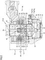
- Fig. 2 shows a first embodiment of such an electromagnetic switching valve 30 in a longitudinal sectional view through the electromagnetic switching valve 30, which is designed as an inlet valve 24 of a high-pressure fuel pump 18.
- the electromagnetic switching valve 30 is arranged in a housing bore 32 of a housing 34 of the high-pressure fuel pump 18.
- the electromagnetic switching valve 30 has a valve region 36 and an actuator region 38, the actuator region 38 having a fixed pole piece 40 and an armature 44 movable along an axis of movement 42.
- the valve region 36 comprises a valve seat 46 and a closing element 48, which cooperate to close the electromagnetic switching valve 30.
- the pole piece 40 and the armature 44 are received together in a sleeve 50, although this need not necessarily be the case.
- a solenoid 52 is pushed onto the sleeve 50 and is thus arranged around the pole piece 40 and the armature 44 in the electromagnetic switching valve 30.
- the armature 44 and the pole piece 40 are arranged directly adjacent to one another, so that an armature surface 54 and a pole piece surface 56 lie directly opposite one another.
- a return spring 58 is arranged between the armature 44 and the pole piece 40 in order to keep the armature 44 and the pole piece 40 at a distance and thus to produce an air gap 60.
- the armature 44 is coupled to an actuating pin 62 which, in operation, moves with the armature 44 along the movement axis 42.
- the actuating pin 62 presses the closing element 48 away from the valve seat 46 or has no contact with the closing element 48, so that the latter is different from the opposite one A force acts to move the valve seat 46 and thus the switching valve 30 can close.
- the solenoid 42 In the energized state of the electromagnetic switching valve 30, the solenoid 42 generates a magnetic field in the electromagnetic switching valve 30, which in Fig. 3 is represented by magnetic field lines 64.
- the magnetic flux of the magnetic field lines 64 is arranged in all metallic / magnetic elements directly adjacent to the solenoid 52, in particular in the pole piece 40 and in the armature 44. This creates a magnetic attraction between the pole piece 40 and armature 44, and the Anchor 44 is pulled with its anchor surface 54 in the direction of pole piece surface 56 of pole piece 40.
- the armature 44 takes the actuating pin 62 with it, so that it loses contact with the closing element 48, and the closing element 48 can thus return to the valve seat 46.
- the return spring 58 pushes the armature 44 away from the pole piece 40 again, since a return force of the return spring 58 acts counter to the magnetic force.
- the air gap 60 is maximally pressed and the actuating pin 62 is pressed onto the closing element 48 again, so that the closing element 48 lifts off the valve seat 46 and the electromagnetic switching valve 30 opens.
- the armature 44 has a magnetic flux concentration area 66, that is to say an area in which the magnetic field lines are guided through the armature 44 on a reduced cross-sectional area, so that they have to concentrate.
- the magnetic flux concentration region 66 is formed in that an armature outer circumference UA has a shoulder 68, so that a first armature outer circumference UA1 and a second armature outer circumference U A2 are formed which are different from one another, the first armature outer circumference UA1 being smaller than the second armature outer circumference U A2 .
- the armature 44 has the first outer armature circumference UA1 in the region in which the armature 44 is assigned directly adjacent to the pole piece 40, that is to say at its upper end region 70.
- the first outer anchor circumference UA1 is a maximum of 3/4 of the second outer anchor circumference UA2.
- a length of the first outer circumference of the anchor UA1 along the movement axis 42 is essentially half of a total length LA of the anchor 44.
- This arrangement of the reduced first armature outer circumference UA1 can produce a targeted magnetic throttle in the armature 44 in order to achieve the advantages described above.
- the course of the magnetic field lines 64 is shown in FIG Fig. 3 where it can be seen that the magnetic field lines 64 are concentrated in the region in which the outer circumference of the armature UA is reduced, so that the overall magnetic flux is concentrated here.
- armature surface 54 which faces the pole piece 40, is smaller at the upper end region 70 than the pole piece surface 56, which is arranged towards the armature 44.
- the anchor surface 54 makes up about half of the pole piece surface 56.
- the two opposing surfaces namely the armature surface 54 and the pole piece surface 56, are the surfaces that generate the magnetic force between armature 44 and pole piece 40.
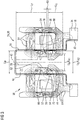
- Fig. 4 and Fig. 5 show an example of the electromagnetic switching valve 30 in which the magnetic throttle is provided in the armature 44 not in the armature 44 as in the first embodiment but in the pole piece 40 by providing the magnetic flux concentration region 66.
- both the armature 44 and the pole piece 40 each form a magnetic flux concentration region 66 and thus a magnetic choke.
- a magnetic flux concentration region 66 in the second embodiment is formed by a constriction 72 in the pole piece 40, so that an outer pole piece circumference UP, which is otherwise constant via the movement axis 42, is reduced in the region of the constriction 72.
- the constriction 72 is arranged in a half 74 of the pole piece 40, which is arranged facing the armature 44, but not, as in the armature 44 in the first embodiment, on one End region, but spaced apart from a pole piece end region 76. It is thereby achieved that, where the pole piece surface 56 is adjacent to the armature surface 54, the maximum magnetic force can act from the pole piece 40 on the armature 44 in order to pull the armature 44 in the direction of the pole piece 40.
- the constriction 72 has a length which corresponds to at least 1/5 a length LP of the pole piece 40 along the movement axis 42.
- the outer pole piece circumference UP is reduced in the region of the constriction 72 by at least 1/4 compared to the constant outer pole piece circumference UP outside the constriction 72.
- the return spring 58 is arranged so that it is supported within the pole piece 40.
- the pole piece 40 has a through bore 78 which widens in a lower pole piece end region 78, which is arranged facing the armature 44, in order to form a spring recess 82.
- the spring recess 82 is defined by side walls 84 of the through bore 78 and by support walls 68, which are formed by the expansion of the through bore 78 in the pole piece end region 78. The return spring 58 is then supported on these support walls 68.
- the constriction 72 is formed along the movement axis 42 at the level of the spring recess 82, in particular in such a way that it does not protrude beyond the spring recess 82.
- the magnetic flux concentration can be achieved in particular in the area of the return spring 58, that is, where the return force of the return spring 58 also acts.
- constriction 72 is advantageously also at the level of the solenoid 52 along the movement axis 42.
- Fig. 5 the course of the magnetic field lines 64 is shown in the pole piece 40, it being possible to see that the magnetic field lines 64 are concentrated in the region of the constriction 72, and thus a magnetic flux concentration can be generated in the pole piece 40.
- the magnetic choke generated in the armature 44 with reference to the first embodiment can thus also be generated in the pole piece 40.
- Fig. 6 shows a diagram that represents the magnetic force generated by the solenoid 52 or the magnetic flux acting in the armature 44 or the pole piece 40 against the magnetic excitation by the solenoid 52.
- the dashed lines correspond to the acting magnetic force in a known arrangement in which the armature 44 or the pole piece 40 have no magnetic flux concentration region 66.
- the solid lines show the effective magnetic force when the armature 44 or the pole piece 40 is formed with a magnetic flux concentration.
- the horizontal line in the diagram shows the magnetic force to be generated by the solenoid 52, which is necessary to overpress the restoring force of the restoring spring 58 so that the armature 44 starts to move.
- the diagram therefore shows a portion of a hysteresis that occurs when the switching valve 30 is operating.
- the magnetic force is reduced by the magnetic choke, however, this can be compensated for by corresponding winding parameters in the solenoid 52 if there is a need here. It would also be possible to readjust this via the electrical resistance that influences the current in the solenoids 52.
Landscapes
- Engineering & Computer Science (AREA)
- General Engineering & Computer Science (AREA)
- Mechanical Engineering (AREA)
- Chemical & Material Sciences (AREA)
- Combustion & Propulsion (AREA)
- Physics & Mathematics (AREA)
- Electromagnetism (AREA)
- Magnetically Actuated Valves (AREA)
- Fuel-Injection Apparatus (AREA)
Description
- Die Erfindung betrifft ein elektromagnetisches Schaltventil für ein Kraftstoffeinspritzsystem einer Brennkraftmaschine, sowie eine Kraftstoffhochdruckpumpe, die ein solches elektromagnetisches Schaltventil aufweist.
- Kraftstoffhochdruckpumpen in Kraftstoffeinspritzsystemen in Brennkraftmaschinen werden dazu verwendet, einen Kraftstoff mit einem hohen Druck zu beaufschlagen, wobei der Druck beispielsweise bei Benzin-Brennkraftmaschinen im Bereich von 150 bar bis 400 bar und bei Diesel-Brennkraftmaschinen im Bereich von 1500 bar bis 2500 bar liegt. Je höher der Druck, der in dem jeweiligen Kraftstoff erzeugt werden kann, desto geringer sind Emissionen, die während der Verbrennung des Kraftstoffes in einer Brennkammer entstehen, was insbesondere vor dem Hintergrund vorteilhaft ist, dass eine Verringerung von Emissionen immer stärker gewünscht wird.
- In dem Kraftstoffeinspritzsystem können an verschiedenen Positionen des Weges, den der Kraftstoff von einem Tank zu der jeweiligen Brennkammer nimmt, Ventilanordnungen vorgesehen sein, beispielsweise als Einlassventil oder Auslassventil an einer Kraftstoffhochdruckpumpe, die den Kraftstoff mit Druck beaufschlagt, aber auch beispielsweise als Entlastungsventil an verschiedensten Positionen des Kraftstoffeinspritzsystems, beispielsweise an einem Common-Rail, das den druckbeaufschlagten Kraftstoff vor der Einspritzung in die Brennkammer speichert.
- Häufig werden hierzu schnell schaltende Magnetventile zur Volumenstrom- und/oder Druckregelung eingesetzt. Je nach Fördermenge und Art hält dabei eine Rückstellfeder ein Schließelement eines Ventilbereiches eines solchen elektromagnetischen Schaltventiles gegen einen Volumenstrom offen oder geschlossen. Der dazugehörige Aktuatorbereich, das heißt der Magnetaktuator, welcher das Schließelement öffnet oder schließt, ist derart gestaltet, dass die Rückstellfeder die Aktuatorkraft des Magnetaktuators in einer bestimmten Zeit überdrücken kann, um somit das Schaltventil zu schalten.
- Diese Schaltventile sind demgemäß als Kombination eines Schaltmagneten, der den Magnetaktuator betreibt, mit einer durch diesen geschalteten Hydraulik, dem Ventilbereich, aufgebaut. Im Betrieb werden somit zwei Schaltzustände der Hydraulik, eine geöffnete Stellung und eine geschlossene Stellung, erreicht. Elektromagnetische Schaltventile sind bekannt aus
DE 10 2014 214231 A1 ,US 2007/176716 A1 ,JP 2002 310029 A DE 10 2009 054838 undUS 2004/050978 A1 . - Der Schaltmagnet weist in dem Aktuatorbereich durch einen krafterzeugenden Luftspalt getrennte Bauteile, nämlich einen beweglichen Anker und einen feststehenden Polkern auf, die durch die Rückstellfeder voneinander auf Abstand gehalten werden. Durch die Aktivierung eines Solenoiden in dem Schaltmagneten durch Beaufschlagung mit elektrischem Strom wird in einer Wicklung des Solenoiden ein Magnetfeld aufgebaut. Dieses Magnetfeld induziert in die umgebenden Metallbauteile, insbesondere in dem Anker und dem Polkern, einen Magnetfluss, sodass zwischen Anker und Polkern eine Magnetkraft aufgebaut wird. Durch diese Magnetkraft wird eine Rückstellkraft der Rückstellfeder überwunden und die gekoppelte Hydraulik gesteuert. Durch ein Wegnehmen des elektrischen Stroms sinkt die Magnetkraft und die Rückstellkraft steuert die Hydraulik in die Ausgangsstellung. Bislang wurde die Dynamik des Schaltventils auf den Betriebszustand ausgelegt, bei dem die schnellste Schaltcharakteristik im Betrieb benötigt wird. Dadurch werden jedoch die Impulskräfte zwischen den schaltenden Magnetbauteilen, nämlich dem Anker und dem Polkern, sehr hoch.
- Das Schaltventil ist bislang so ausgelegt, dass sich in dem Arbeitspunkt, bei dem der maximale Luftspalt zwischen Anker und Polkern vorliegt, und bei dem sich ein Kräftegleichgewicht zwischen der Rückstellfeder und der Magnetkraft des Solenoiden einstellt, eine möglichst hohe Magnetflussdichte im Luftspalt zwischen Anker und Polkern einstellt, damit die bewegten Bauteile möglichst schnell zur Bewegung angeregt werden. Innerhalb des Bewegungsvorgangs werden die bewegten Bauteile dann durch die Magnetkraft weiter beschleunigt und der Luftspalt verringert sich. Im Zustand des minimalen Luftspalts ist die Magnetkraft dann maximal.
- Die Impulskräfte sind von der Masse der bewegten Bauteile und von deren Geschwindigkeit abhängig. Bei hohen Impulskräften ist die Folge, dass zwischen den Bauteilen ein hoher Verschleiß auftreten kann und die Schallgeräusche im Betrieb sehr hoch sind. Geräusche treten nämlich bei jeder Änderung des Schaltzustandes auf, sowohl durch den Solenoiden selbst, als auch durch die Hydraulik. Es schlagen jeweils wenigstens zwei Bauteile aufeinander und erzeugen so Geräusche.
- Beispielsweise wird ein solches Schaltventil als digitales Einlassventil an einer Kraftstoffhochdruckpumpe in einem Kraftstoffeinspritzsystem einer Brennkraftmaschine verwendet. Die Schaltzeit eines solchen Einlassventils ist dabei so ausgelegt, dass es auch bei der höchsten Motordrehzahl der Brennkraftmaschine in der Lage ist, schnell zu schalten. Dies steht jedoch im Gegensatz zu dem Ziel, dass in einem anderen Betriebszustand der Brennkraftmaschine, nämlich im Motorleerlauf, keine nennenswerten Geräusche erzeugt werden sollten.
- Bislang wurde das Schaltventil auf die Schaltzeit für den Betriebspunkt mit der höchsten Schaltdynamik ausgelegt. Es wurde versucht, Geräusche und Verschleiß für Bewegungen, die entgegen der Schaltrichtung des Schaltmagneten gerichtet sind, mit kurzzeitigen Stromimpulsen zur Erhöhung der Magnetkraft abzufangen. Es ist jedoch schwierig, Bewegungen in Schaltrichtung des Schaltventiles abzuschwächen.
- Aufgabe der Erfindung ist es daher, ein elektromagnetisches Schaltventil bereitzustellen, bei dem in allen Betriebspunkten eine Geräuschentwicklung auf ein Minimum reduziert werden kann.
- Diese Aufgabe wird mit einem elektromagnetischen Schaltventil mit der Merkmalskombination des Anspruches 1 gelöst.
- Eine Kraftstoffhochdruckpumpe, die ein solches elektromagnetisches Schaltventil aufweist, ist Gegenstand des nebengeordneten Anspruches.
- Vorteilhafte Ausgestaltungen der Erfindung sind Gegenstand der abhängigen Ansprüche.
- Ein elektromagnetisches Schaltventil für ein Kraftstoffeinspritzsystem einer Brennkraftmaschine weist einen Ventilbereich mit einem Schließelement zum Schließen des Schaltventiles und einen Aktuatorbereich zum Bewegen des Schließelementes entlang einer Bewegungsachse auf. Der Aktuatorbereich umfasst einen entlang der Bewegungsachse beweglichen Anker, der zum Bewegen des Schließelementes mit dem Schließelement gekoppelt ist, ein feststehendes Polstück und einen Solenoiden zum Erzeugen eines Magnetflusses in dem Anker und dem Polstück. Der Anker weist einen Magnetflusskonzentrationsbereich auf, in dem ein Magnetfluss sättigbar ist und der dadurch gebildet ist, dass ein Ankeraußenumfang einen Absatz aufweist, sodass der Anker einen kleineren, ersten Ankeraußenumfang und einen größeren, zweiten Ankeraußenumfang aufweist, wobei der erste Ankeraußenumfang maximal 3/4 des zweiten Ankeraußenumfangs (UA2) beträgt.
- Dadurch reduziert sich der Ankeraußenumfang an dem Absatz, und die Magnetfeldlinien, die durch den Anker hindurchfließen, müssen sich in diesem verengten Bereich den Raum teilen. Dadurch erfolgt eine Konzentration der Magnetfeldlinien und somit des Magnetflusses in diesem Bereich des Ankers. Durch diese Einschnürung wird dann die magnetische Drossel wie oben beschrieben gebildet.
- Der erste Ankeraußenumfang beträgt im Wesentlichen entlang der Bewegungsachse die Hälfte einer Gesamtlänge des Ankers.
- Der Anker und das Polstück sind benachbart zueinander angeordnet, wobei der Bereich des Ankers mit dem ersten Ankeraußenumfang zu dem Polstück hingewandt angeordnet ist.
- Demgemäß ist der Absatz in dem Anker in einer definierten Höhe und mit einem definierten Durchmesser und einer definierten Länge angeordnet, um so eine definierte Magnetflusskonzentration in dem Anker erreichen zu können.
- Durch die Einschnürung stellen sich insgesamt die folgenden Effekte ein:
Durch die Einschnürung wird nicht nur eine Magnetflusskonzentration in dem Anker erreicht, sondern auch insgesamt die Masse des Ankers reduziert. Außerdem wird die gewünschte Magnetkraft schneller als bislang erreicht, was mit einer Schaltzeitreduktion des Schaltventiles einhergeht. Gleichzeitig wird der Anker in der Bewegungsphase nicht so stark beschleunigt, wobei dennoch die Geschwindigkeit der bisher bekannten entspricht. Insgesamt wird die Gesamtschaltzeit reduziert und somit verbessert. - Vorzugsweise liegen sich eine Ankerfläche und eine Polstückfläche direkt gegenüber, wobei die Ankerfläche des Ankers im Bereich des ersten Ankeraußenumfangs etwa die Hälfte der Polstückfläche beträgt.
- In besonders vorteilhafter Ausgestaltung weist das Polstück eine Einschnürung in einem Polstückaußenumfang zum Bilden eines Magnetflusskonzentrationsbereiches auf.
- Dadurch kann auch eine Magnetflusskonzentration in dem Polstück erreicht werden, was wiederum zu einer verbesserten Schaltzeit des Schaltventiles führt.
- Dabei ist die Einschnürung in einer dem Anker zugewandten Hälfte des Polstückes angeordnet, wobei die Einschnürung insbesondere wenigstens 1/5 einer Gesamtlänge des Polstückes entlang der Bewegungsachse beträgt.
- Vorzugsweise ist der Polstückaußenumfang im Bereich der Einschnürung um wenigstens 1/4 reduziert.
- Demgemäß ist die Einschnürung in einer definierten Höhe in dem Polstück und mit einem definierten Durchmesser und einer definierten Länge angeordnet, um so eine definierte Magnetflusskonzentration in dem Polstück erreichen zu können.
- Besonders vorteilhaft befindet sich die Einschnürung des Polstückes entlang der Bewegungsachse auf Höhe einer Federausnehmung einer Rückstellfeder zwischen Polstück und Anker.
- Weiter vorteilhaft befindet sich die Einschnürung entlang der Bewegungsachse auf Höhe des Solenoiden.
- Eine Kraftstoffhochdruckpumpe für ein Kraftstoffeinspritzsystem einer Brennkraftmaschine weist vorteilhaft ein oben beschriebenes elektromagnetisches Schaltventil auf.
- Dabei kann das Schaltventil beispielsweise als Einlassventil für die Kraftstoffhochdruckpumpe oder auch als Auslassventil gebildet sein. Es ist jedoch auch möglich, das beschriebene Schaltventil als Druckregelventil vorzusehen, das beispielsweise an einem Common-Rail eines Kraftstoffeinspritzsystems angeordnet ist.
- Vorteilhafte Ausgestaltungen der Erfindungen werden nachfolgend anhand der beigefügten Zeichnungen näher erläutert. Darin zeigt:
- Fig. 1
- eine schematische Übersichtsdarstellung eines Kraftstoffeinspritzsystems einer Brennkraftmaschine, das an verschiedenen Positionen ein elektromagnetisches Schaltventil aufweisen kann;
- Fig. 2
- eine Längsschnittdarstellung eines der Schaltventile aus
Fig. 1 als Einlassventil an der Kraftstoffhochdruckpumpe in einer ersten Ausführungsform; - Fig. 3
- eine Längsschnittdarstellung des Schaltventils aus
Fig. 2 mit im Betrieb wirkenden Magnetfeldlinien; - Fig. 4
- eine Längsschnittdarstellung eines der Schaltventile aus
Fig. 1 als Einlassventil an der Kraftstoffhochdruckpumpe in einem Beispiel; - Fig. 5
- eine Längsschnittdarstellung des Schaltventils aus
Fig. 4 mit im Betrieb wirkenden Magnetfeldlinien; und - Fig. 6
- ein Diagramm, das die im Betrieb wirkende Magnetkraft der Schaltventile aus
Fig. 2 undFig. 4 gegen die magnetische Anregung durch den Solenoiden darstellt. -
Fig. 1 zeigt eine schematische Übersichtsdarstellung eines Kraftstoffeinspritzsystems 10 einer Brennkraftmaschine, das einen Kraftstoff 12 aus einem Tank 14 über eine Vorförderpumpe 16, eine Kraftstoffhochdruckpumpe 18 und einen Kraftstoffhochdruckspeicher 20 zu Injektoren 22 fördert, die den Kraftstoff 12 dann in Brennräume der Brennkraftmaschine einspritzen. - Der Kraftstoff 12 wird über ein Einlassventil 24 in die Kraftstoffhochdruckpumpe 18 eingebracht, über ein Auslassventil 26 druckbeaufschlagt aus der Kraftstoffhochdruckpumpe 18 herausgelassen, und dann dem Kraftstoffhochdruckspeicher 20 zugeführt. An dem Kraftstoffhochdruckspeicher 20 ist ein Druckregelventil 28 angeordnet, um den Druck des Kraftstoffes 12 in dem Kraftstoffhochdruckspeicher 20 regeln zu können.
- Sowohl das Einlassventil 24, als auch das Auslassventil 26, als auch das Druckregelventil 28 können als elektromagnetische Schaltventile 30 ausgebildet sein und daher aktiv betrieben werden.
-
Fig. 2 zeigt eine erste Ausführungsform eines solchen elektromagnetischen Schaltventiles 30 in einer Längsschnittdarstellung durch das elektromagnetische Schaltventil 30, das als Einlassventil 24 einer Kraftstoffhochdruckpumpe 18 ausgebildet ist. - Das elektromagnetische Schaltventil 30 ist in einer Gehäusebohrung 32 eines Gehäuses 34 der Kraftstoffhochdruckpumpe 18 angeordnet. Das elektromagnetische Schaltventil 30 weist einen Ventilbereich 36 und einen Aktuatorbereich 38 auf, wobei der Aktuatorbereich 38 ein feststehendes Polstück 40 und einen entlang einer Bewegungsachse 42 beweglichen Anker 44 aufweist. Der Ventilbereich 36 umfasst einen Ventilsitz 46 und ein Schließelement 48, die zum Schließen des elektromagnetischen Schaltventiles 30 zusammenwirken.
- In der in
Fig. 2 gezeigten Ausführungsform sind das Polstück 40 und der Anker 44 gemeinsam in einer Hülse 50 aufgenommen, wobei dies jedoch nicht zwingend der Fall sein muss. - Ein Solenoid 52 ist auf die Hülse 50 aufgeschoben und befindet sich somit um das Polstück 40 und den Anker 44 herum angeordnet in dem elektromagnetischen Schaltventil 30.
- Der Anker 44 und das Polstück 40 sind direkt benachbart zueinander angeordnet, sodass eine Ankerfläche 54 und eine Polstückfläche 56 sich direkt gegenüberliegen.
- Es ist eine Rückstellfeder 58 zwischen dem Anker 44 und dem Polstück 40 angeordnet, um Anker 44 und Polstück 40 auf Abstand zu halten und somit einen Luftspalt 60 zu erzeugen.
- Der Anker 44 ist mit einem Betätigungsstift 62 gekoppelt, der sich im Betrieb mit dem Anker 44 entlang der Bewegungsachse 42 bewegt.
- Je nach Schaltzustand und somit Position des Ankers 44 entlang der Bewegungsachse 42 drückt der Betätigungsstift 62 das Schließelement 48 von dem Ventilsitz 46 weg oder hat keinen Kontakt zu dem Schließelement 48, sodass dieses sich, wenn von der gegenüberliegenden Seite eine Kraft wirkt, auf den Ventilsitz 46 zu bewegen und somit das Schaltventil 30 schließen kann.
- In bestromtem Zustand des elektromagnetischen Schaltventiles 30 erzeugt der Solenoid 42 ein Magnetfeld in dem elektromagnetischen Schaltventil 30, das in
Fig. 3 durch Magnetfeldlinien 64 dargestellt ist. Wie inFig. 3 zu sehen ist, ist dabei der Magnetfluss der Magnetfeldlinien 64 in allen direkt zu dem Solenoiden 52 benachbarten metallischen/magnetischen Elementen angeordnet, insbesondere in dem Polstück 40 und in dem Anker 44. Dadurch entsteht eine magnetische Anziehungskraft zwischen Polstück 40 und Anker 44, und der Anker 44 wird mit seiner Ankerfläche 54 in Richtung auf die Polstückfläche 56 des Polstückes 40 gezogen. Dabei nimmt der Anker 44 den Betätigungsstift 62 mit, sodass dieser den Kontakt mit dem Schließelement 48 verliert, und das Schließelement 48 so auf den Ventilsitz 46 zurückkehren kann. - Da der Anker 44 sich bei eingeschaltetem Solenoiden 52 auf das Polstück 40 zu bewegt, ist der Luftspalt 60 im eingeschalteten Zustand minimal.
- Im ausgeschalteten Zustand dagegen drückt die Rückstellfeder 58 den Anker 44 wieder von dem Polstück 40 weg, da eine Rückstellkraft der Rückstellfeder 58 entgegen der Magnetkraft wirkt. Der Luftspalt 60 wird maximal und der Betätigungsstift 62 wieder auf das Schließelement 48 gedrückt, sodass das Schließelement 48 vom Ventilsitz 46 abhebt und das elektromagnetische Schaltventil 30 öffnet.
- In der in
Fig. 2 undFig. 3 gezeigten Ausführungsform ist zu sehen, dass der Anker 44 einen Magnetflusskonzentrationsbereich 66 aufweist, das heißt einen Bereich, in dem die Magnetfeldlinien auf einer verringerten Querschnittfläche durch den Anker 44 geführt werden, sodass sie sich konzentrieren müssen. - Der Magnetflusskonzentrationsbereich 66 ist dadurch gebildet, dass ein Ankeraußenumfang UA einen Absatz 68 aufweist, sodass sich ein erster Ankeraußenumfang UA1 und ein zweiter Ankeraußenumfang UA2 bilden, die unterschiedlich zueinander sind, wobei der erste Ankeraußenumfang UA1 kleiner ist als der zweite Ankeraußenumfang UA2.
- Es ist zu sehen, dass der Anker 44 den ersten Ankeraußenumfang UA1 in dem Bereich aufweist, in dem der Anker 44 direkt benachbart zu dem Polstück 40 zugeordnet ist, das heißt an seinem oberen Endbereich 70.
- Der erste Ankeraußenumfang UA1 beträgt dabei maximal 3/4 des zweiten Ankeraußenumfangs UA2. Außerdem beträgt eine Länge des ersten Ankeraußenumfangs UA1 entlang der Bewegungsachse 42 im Wesentlichen die Hälfte einer Gesamtlänge LA des Ankers 44.
- Durch diese Anordnung des reduzierten ersten Ankeraußenumfanges UA1 kann eine gezielte magnetische Drossel in dem Anker 44 erzeugt werden, um die oben beschriebenen Vorteile zu erreichen. Der Verlauf der Magnetfeldlinien 64 ist dabei in
Fig. 3 gezeigt, wobei zu sehen ist, dass die Magnetfeldlinien 64 sich in dem Bereich, in dem der Ankeraußenumfang UA reduziert ist, konzentrieren, sodass sich hier insgesamt der Magnetfluss konzentriert. - Aus
Fig. 2 geht weiter hervor, dass die Ankerfläche 54, die zu dem Polstück 40 gewandt ist, an dem oberen Endbereich 70 kleiner ist als die Polstückfläche 56, die zu dem Anker 44 hin gerichtet angeordnet ist. Dabei macht die Ankerfläche 54 etwa die Hälfte der Polstückfläche 56 aus. - Die beiden sich gegenüberliegenden Flächen, nämlich die Ankerfläche 54 und die Polstückfläche 56, sind die Flächen, die die Magnetkraft zwischen Anker 44 und Polstück 40 erzeugen.
- Bei der herkömmlichen Auslegung, das heißt, wenn der Anker 44 einen konstanten Ankeraußenumfang UA aufweist, stellt sich eine Magnetflussdichte ein, die an der Ankerfläche 54 und an der Polstückfläche 56 wertmäßig etwa im gleichen Bereich liegt. Nun sind die Ankerfläche 54 und die Polstückfläche 56 jedoch unterschiedlich groß ausgebildet, sodass der Magnetfluss kurz nachdem die Magnetkraft des Solenoiden 52 die Rückstellkraft der Rückstellfeder 58 überdrückt hat, in Sättigung kommt, wie später mit Bezug auf
Fig. 6 erläutert wird. -
Fig. 4 undFig. 5 zeigen ein Beispiel des elektromagnetischen Schaltventiles 30, bei der die magnetische Drossel durch Vorsehen des Magnetflusskonzentrationsbereiches 66 nicht in dem Anker 44 wie in der ersten Ausführungsform, sondern in dem Polstück 40 vorgesehen ist. - Es ist erfindungsgemäß und gemäß der zweiten Ausführungsform möglich, dass sowohl der Anker 44 als auch das Polstück 40 jeweils einen Magnetflusskonzentrationsbereich 66 und somit eine magnetische Drossel bilden.
- Ein Magnetflusskonzentrationsbereich 66 in der zweiten Ausführungsform ist durch eine Einschnürung 72 in dem Polstück 40 gebildet, sodass ein Polstückaußenumfang UP, der ansonsten über die Bewegungsachse 42 konstant ist, sich in dem Bereich der Einschnürung 72 reduziert.
- Die Einschnürung 72 ist in einer Hälfte 74 des Polstückes 40 angeordnet, die dem Anker 44 zugewandt angeordnet ist, jedoch nicht, wie beim Anker 44 in der ersten Ausführungsform, an einem Endbereich, sondern zu einem Polstückendbereich 76 beabstandet. Dadurch wird erreicht, dass dort, wo die Polstückfläche 56 benachbart zu der Ankerfläche 54 ist, die maximale Magnetkraft von dem Polstück 40 auf den Anker 44 wirken kann, um den Anker 44 in Richtung auf das Polstück 40 zu ziehen.
- Die Einschnürung 72 hat eine Länge, die wenigstens 1/5 einer Länge LP des Polstückes 40 entlang der Bewegungsachse 42 entspricht. Der Polstückaußenumfang UP ist im Bereich der Einschnürung 72 um wenigstens 1/4 im Vergleich zu dem konstanten Polstückaußenumfang UP außerhalb der Einschnürung 72 reduziert.
- Wie in
Fig. 4 ,Fig. 5 , aber auch inFig. 2 undFig. 3 , zu sehen ist, ist die Rückstellfeder 58 so angeordnet, dass sie sich innerhalb des Polstückes 40 abstützt. Dazu weist das Polstück 40 eine Durchgangsbohrung 78 auf, die sich in einem unteren Polstückendbereich 78, der zu dem Anker 44 hin gewandt angeordnet ist, erweitert, um eine Federausnehmung 82 zu bilden. Die Federausnehmung 82 ist dabei durch Seitenwände 84 der Durchgangsbohrung 78 und durch Abstützwände 68 definiert, die sich durch die Erweiterung der Durchgangsbohrung 78 im Polstückendbereich 78 bilden. An diesen Abstützwänden 68 stützt sich dann die Rückstellfeder 58 ab. - Wie in
Fig. 4 zu sehen ist, ist die Einschnürung 72 entlang der Bewegungsachse 42 auf Höhe der Federausnehmung 82 gebildet, und zwar insbesondere so, dass sie nicht über die Federausnehmung 82 hinausragt. Dadurch kann die Magnetflusskonzentration insbesondere in dem Bereich der Rückstellfeder 58 erzielt werden, das heißt dort, wo auch die Rückstellkraft der Rückstellfeder 58 wirkt. - Weiter ist zu sehen, dass sich die Einschnürung 72 vorteilhaft auch auf Höhe des Solenoiden 52 entlang der Bewegungsachse 42 befindet.
- In
Fig. 5 ist der Verlauf der Magnetfeldlinien 64 in dem Polstück 40 dargestellt, wobei zu sehen ist, dass sich im Bereich der Einschnürung 72 die Magnetfeldlinien 64 konzentrieren, und somit eine Magnetflusskonzentration in dem Polstück 40 erzeugt werden kann. Damit kann auch die mit Bezug auf die erste Ausführungsform in dem Anker 44 erzeugte magnetische Drossel in dem Polstück 40 erzeugt werden. - Die Wirkungsweise der magnetischen Drosseln im Anker 44 und/oder Polstück 40 werden nachfolgend mit Bezug auf
Fig. 6 erläutert. -
Fig. 6 zeigt ein Diagramm, das die durch den Solenoiden 52 erzeugte Magnetkraft bzw. den wirkenden Magnetfluss in dem Anker 44 bzw. dem Polstück 40 gegen die magnetische Anregung durch den Solenoiden 52 darstellt. - Die gestrichelten Linien entsprechen der wirkenden Magnetkraft bei einer bekannten Anordnung, bei der der Anker 44 bzw. das Polstück 40 keinen Magnetflusskonzentrationsbereich 66 aufweisen. Die durchgezogenen Linien dagegen zeigen die wirkende Magnetkraft bei einer Ausbildung des Ankers 44 bzw. des Polstücks 40 mit Magnetflusskonzentration.
- Die waagrechte Linie in dem Diagramm zeigt die von dem Solenoiden 52 zu erzeugende Magnetkraft an, die nötig ist, um die Rückstellkraft der Rückstellfeder 58 zu überdrücken, sodass sich der Anker 44 in Bewegung setzt.
- Die beiden Linien, die den Anschaltvorgang des Schaltventiles 30 darstellen, sind dabei mit "AN" gekennzeichnet.
- Die beiden Linien, die den Ausschaltvorgang des Schaltventiles 30 darstellen, sind dabei mit "AUS" gekennzeichnet.
- Insgesamt zeigt das Diagramm daher jeweils einen Teilbereich einer Hysterese, die beim Betrieb des Schaltventiles 30 auftritt.
- Es ist aus dem Diagramm zu entnehmen, dass beim Ausschalten bei fehlender magnetischer Drosselung in dem Anker 44/dem Polstück 40 die Magnetkraft nach Überdrücken der Rückstellkraft weiter stark ansteigt und kaum in ein Sättigungsbereich gelangt. Dagegen ist zu sehen, dass, wenn eine magnetische Drosselung am Anker 44/am Polstück 40 vorliegt, kurz nach Überdrücken der Rückstellkraft der Rückstellfeder 58 die Magnetkraft in einen Sättigungsbereich kommt und nicht weiter ansteigt. Bewirkt wird somit eine verringerte Beschleunigung des Ankers 44 in der Bewegungsphase, sodass dann auch der Impuls beim Einschlag des Ankers 44 in das Polstück 40 reduziert ist. Die Geräuschentwicklung beim Anschalten des Schaltventiles 30 kann somit deutlich reduziert werden.
- Beim Ausschalten ist zu erkennen, dass die Magnetkraft bei vorliegender magnetischer Drossel im Anker 44/im Polstück 40 früher zu dem Punkt zurückkehrt, zu dem sich das Kräftegleichgewicht mit der Rückstellkraft der Rückstellfeder 58 einstellt, als dies der Fall ist, wenn die magnetische Drossel nicht vorliegt.
- Das bedeutet, der Ausschaltvorgang des Schaltventiles 30 ist schneller als dies bisher der Fall war. Dadurch wird die Gesamtschaltzeit des Schaltventiles 30 deutlich reduziert und somit verbessert zum Stand der Technik.
- Zwar wird auch insgesamt, wie aus dem Diagramm in
Fig. 6 zu sehen ist, die Magnetkraft durch die magnetische Drossel reduziert, dies kann jedoch durch entsprechende Wickelparameter in dem Solenoiden 52 ausgeglichen werden, wenn hier ein Bedarf besteht. Es wäre auch möglich, dies über den elektrischen Widerstand, der den Strom in den Solenoiden 52 beeinflusst, nachzujustieren.
Claims (7)
- Elektromagnetisches Schaltventil (30) für ein Kraftstoffeinspritzsystem (10) einer Brennkraftmaschine, aufweisend:- einen Ventilbereich (36) mit einem Schließelement (48) zum Schließen des Schaltventiles (30); und- einen Aktuatorbereich (38) zum Bewegen des Schließelementes (48) entlang einer Bewegungsachse (42);wobei der Aktuatorbereich (38) einen entlang der Bewegungsachse (42) beweglichen Anker (44), der zum Bewegen des Schließelementes (48) mit dem Schließelement (48) gekoppelt ist, ein feststehendes Polstück (40) und einen Solenoiden (52) zum Erzeugen eines Magnetflusses in dem Anker (44) und dem Polstück (40) aufweist, wobei der Anker (44) einen Magnetflusskonzentrationsbereich (66) aufweist, in dem ein Magnetfluss sättigbar ist und der dadurch gebildet ist, dass ein Ankeraußenumfang (UA) einen Absatz (68) aufweist, sodass der Anker (44) einen ersten Ankeraußenumfang (UA1) und einen zweiten Ankeraußenumfang (UA2) aufweist, wobei der erste Ankeraußenumfang (UA1) kleiner ist als der zweite Ankeraußenumfang (UA2) und maximal 3/4 des zweiten Ankeraußenumfangs (UA2) beträgt.
- Elektromagnetisches Schaltventil (30) nach Anspruch 1, dadurch gekennzeichnet, dass der erste Ankeraußenumfang (UA1) entlang der Bewegungsachse (42) im Wesentlichen die Hälfte (74) einer Gesamtlänge (LA) des Ankers (44) beträgt.
- Elektromagnetisches Schaltventil (30) nach einem der Ansprüche 1 bis 2,
dadurch gekennzeichnet, dass der Anker (44) und das Polstück (40) benachbart zueinander angeordnet sind, wobei der Bereich des Ankers (44) mit dem ersten Ankeraußenumfang (UA1) zu dem Polstück (40) gewandt angeordnet ist. - Elektromagnetisches Schaltventil (30) nach Anspruch 3, dadurch gekennzeichnet, dass sich eine Ankerfläche (54) und eine Polstückfläche (56) direkt gegenüberliegen, wobei die Ankerfläche (54) des Ankers (44) im Bereich des ersten Ankeraußenumfangs (UA1) etwa die Hälfte (74) der Polstückfläche (56) beträgt.
- Elektromagnetisches Schaltventil (30) nach einem der Ansprüche 1 bis 4,
dadurch gekennzeichnet, dass das Polstück (40) eine Einschnürung (72) in einem Polstückaußenumfang (UP) zum Bilden eines Magnetflusskonzentrationsbereichs (66) aufweist. - Elektromagnetisches Schaltventil (30) nach Anspruch 5, dadurch gekennzeichnet, dass die Einschnürung (72) in einer dem Anker (44) zugewandten Hälfte (74) des Polstückes (40) angeordnet ist, wobei die Einschnürung (72) insbesondere wenigstens 1/5 einer Gesamtlänge (LP) des Polstückes (40) entlang der Bewegungsachse (42) beträgt, wobei der Polstückaußenumfang (UP) im Bereich der Einschnürung (72) insbesondere um wenigstens 1/4 reduziert ist.
- Kraftstoffhochdruckpumpe (18) für ein Kraftstoffeinspritzsystem (10) einer Brennkraftmaschine, aufweisend ein elektromagnetisches Schaltventil (30) nach einem der Ansprüche 1 bis 6.
Priority Applications (5)
| Application Number | Priority Date | Filing Date | Title |
|---|---|---|---|
| EP17156169.9A EP3364015B8 (de) | 2017-02-15 | 2017-02-15 | Elektromagnetisches schaltventil und kraftstoffhochdruckpumpe |
| KR1020170165480A KR102017955B1 (ko) | 2017-02-15 | 2017-12-04 | 전자기 스위칭 밸브 및 고압 연료 펌프 |
| CN201810149415.3A CN108425775B (zh) | 2017-02-15 | 2018-02-13 | 电磁的开关阀和燃料高压泵 |
| JP2018023926A JP6542405B2 (ja) | 2017-02-15 | 2018-02-14 | 電磁切換弁および高圧燃料ポンプ |
| US15/897,398 US20180230955A1 (en) | 2017-02-15 | 2018-02-15 | Electromagnetic Switching Valve and High-Pressure Fuel Pump |
Applications Claiming Priority (1)
| Application Number | Priority Date | Filing Date | Title |
|---|---|---|---|
| EP17156169.9A EP3364015B8 (de) | 2017-02-15 | 2017-02-15 | Elektromagnetisches schaltventil und kraftstoffhochdruckpumpe |
Publications (3)
| Publication Number | Publication Date |
|---|---|
| EP3364015A1 EP3364015A1 (de) | 2018-08-22 |
| EP3364015B1 true EP3364015B1 (de) | 2020-04-08 |
| EP3364015B8 EP3364015B8 (de) | 2020-06-03 |
Family
ID=58046547
Family Applications (1)
| Application Number | Title | Priority Date | Filing Date |
|---|---|---|---|
| EP17156169.9A Active EP3364015B8 (de) | 2017-02-15 | 2017-02-15 | Elektromagnetisches schaltventil und kraftstoffhochdruckpumpe |
Country Status (5)
| Country | Link |
|---|---|
| US (1) | US20180230955A1 (de) |
| EP (1) | EP3364015B8 (de) |
| JP (1) | JP6542405B2 (de) |
| KR (1) | KR102017955B1 (de) |
| CN (1) | CN108425775B (de) |
Families Citing this family (3)
| Publication number | Priority date | Publication date | Assignee | Title |
|---|---|---|---|---|
| US10947880B2 (en) * | 2018-02-01 | 2021-03-16 | Continental Powertrain USA, LLC | Injector for reductant delivery unit having fluid volume reduction assembly |
| US10683825B1 (en) | 2018-12-04 | 2020-06-16 | Delphi Technologies Ip Limited | Fuel pump and inlet valve assembly thereof |
| JP7115328B2 (ja) * | 2019-01-15 | 2022-08-09 | 株式会社デンソー | 電磁弁 |
Family Cites Families (16)
| Publication number | Priority date | Publication date | Assignee | Title |
|---|---|---|---|---|
| JPH0656140B2 (ja) * | 1984-12-26 | 1994-07-27 | 日本電装株式会社 | 電磁式燃料噴射弁 |
| JPS6436776U (de) * | 1987-08-28 | 1989-03-06 | ||
| JP3666246B2 (ja) * | 1998-05-25 | 2005-06-29 | Nok株式会社 | ソレノイドバルブ |
| US6994406B1 (en) * | 1998-12-16 | 2006-02-07 | Kelsey-Hayes Company | EHB proportional solenoid valve with stepped gap armature |
| US6431474B2 (en) * | 1999-05-26 | 2002-08-13 | Siemens Automotive Corporation | Compressed natural gas fuel injector having magnetic pole face flux director |
| JP2002310029A (ja) * | 2001-04-10 | 2002-10-23 | Denso Corp | 燃料噴射弁 |
| JP3882892B2 (ja) * | 2001-11-07 | 2007-02-21 | 株式会社デンソー | 燃料噴射装置 |
| JP2003343384A (ja) * | 2002-05-22 | 2003-12-03 | Mitsubishi Electric Corp | 高圧燃料供給装置 |
| JP3945357B2 (ja) * | 2002-09-18 | 2007-07-18 | 株式会社デンソー | 燃料噴射装置 |
| JP2007205234A (ja) * | 2006-02-01 | 2007-08-16 | Denso Corp | 燃料噴射弁 |
| DE102009054838A1 (de) * | 2009-12-17 | 2011-06-22 | Robert Bosch GmbH, 70469 | Elektromagnetisches Schaltventil mit einer Magnetspule und einem in einem Gehäuse axial bewegbaren Anker |
| DE102011090006B4 (de) * | 2011-12-28 | 2015-03-26 | Continental Automotive Gmbh | Ventil |
| US9377124B2 (en) * | 2013-10-15 | 2016-06-28 | Continental Automotive Systems, Inc. | Normally low solenoid valve assembly |
| DE102014214231A1 (de) * | 2014-07-22 | 2016-01-28 | Robert Bosch Gmbh | Elektromagnetische Stelleinheit für ein Saugventil sowie Saugventil |
| DE102014215774B4 (de) * | 2014-08-08 | 2016-06-30 | Continental Automotive Gmbh | Vorrichtung für eine Hochdruckpumpe für ein Kraftfahrzeug |
| DE102015218768B3 (de) * | 2015-09-29 | 2017-03-02 | Continental Automotive Gmbh | Elektromagnetischer Aktor, elektromagnetisches Ventil und Kraftstoffhochdruckpumpe |
-
2017
- 2017-02-15 EP EP17156169.9A patent/EP3364015B8/de active Active
- 2017-12-04 KR KR1020170165480A patent/KR102017955B1/ko active IP Right Grant
-
2018
- 2018-02-13 CN CN201810149415.3A patent/CN108425775B/zh active Active
- 2018-02-14 JP JP2018023926A patent/JP6542405B2/ja active Active
- 2018-02-15 US US15/897,398 patent/US20180230955A1/en not_active Abandoned
Non-Patent Citations (1)
| Title |
|---|
| None * |
Also Published As
| Publication number | Publication date |
|---|---|
| EP3364015A1 (de) | 2018-08-22 |
| EP3364015B8 (de) | 2020-06-03 |
| KR20180094472A (ko) | 2018-08-23 |
| US20180230955A1 (en) | 2018-08-16 |
| CN108425775A (zh) | 2018-08-21 |
| CN108425775B (zh) | 2020-09-15 |
| JP2018135882A (ja) | 2018-08-30 |
| JP6542405B2 (ja) | 2019-07-10 |
| KR102017955B1 (ko) | 2019-09-03 |
Similar Documents
| Publication | Publication Date | Title |
|---|---|---|
| EP0745764B1 (de) | Brennstoffeinspritzventil für Verbrennungskraftmaschinen | |
| DE3541938C2 (de) | Magnet-Überströmventil | |
| DE19932548A1 (de) | Dualelektromagneten mit einer Einzelschaltung und Brennstoffeinspritzvorrichtung, die diese anwendet | |
| DE102011013702B4 (de) | Elektromagnetischer Aktor | |
| DE19650865A1 (de) | Magnetventil | |
| EP3478957B1 (de) | Ventil zum eindüsen von gasförmigem kraftstoff | |
| DE102007032741A1 (de) | Kraftstoffeinspritzventil für Brennkraftmaschinen | |
| WO2000052326A1 (de) | Anordnung und verfahren zur regelung eines steuerventils für ein diesel-einspritzsystem | |
| EP3409984B1 (de) | Kolbenschieberventil | |
| EP1203151B1 (de) | Zweistufiges magnetventil für einen injektor von brennkarftmaschinen | |
| EP3364015B1 (de) | Elektromagnetisches schaltventil und kraftstoffhochdruckpumpe | |
| DE10004961B4 (de) | Brennstoffeinspritzventil und Verfahren zu dessen Betrieb | |
| EP2462335B1 (de) | Vorrichtung zur kraftstoffhochdruckeinspritzung | |
| DE102016220326A1 (de) | Ventil zum Zumessen eines gasförmigen oder flüssigen Kraftstoffs | |
| DE3601710C2 (de) | Kraftstoffeinspritzvorrichtung für Brennkraftmaschinen | |
| EP2256333B1 (de) | Aktiv schließendes Magnetventil für Magnetinjektoren | |
| DE10009037A1 (de) | Steuerventil für eine Kraftstoff-Einspritzdüse | |
| EP3364016B1 (de) | Elektromagnetisches schaltventil und kraftstoffhochdruckpumpe | |
| DE10005182A1 (de) | Elektromagnetisches Einspritzventil zur Steuerung einer in eine Verbrennungskraftmaschine einzuspeisenden Kraftstoffmenge | |
| DE2343285A1 (de) | Elektromagnetisch betaetigbares kraftstoffeinspritzventil fuer brennkraftmaschinen | |
| EP3361085B1 (de) | Elektromagnetisches schaltventil und kraftstoffhochdruckpumpe | |
| DE102008044157A1 (de) | Ventilanordnung für Kraftstoffhochdruckeinspritzung | |
| EP3346121B1 (de) | Magnetventil für ein kraftstoffeinspritzsystem und kraftstoffhochdruckpumpe | |
| EP1961953A1 (de) | Mehrwegeventil | |
| DE102008058108B4 (de) | Druckregelventil |
Legal Events
| Date | Code | Title | Description |
|---|---|---|---|
| PUAI | Public reference made under article 153(3) epc to a published international application that has entered the european phase |
Free format text: ORIGINAL CODE: 0009012 |
|
| STAA | Information on the status of an ep patent application or granted ep patent |
Free format text: STATUS: THE APPLICATION HAS BEEN PUBLISHED |
|
| AK | Designated contracting states |
Kind code of ref document: A1 Designated state(s): AL AT BE BG CH CY CZ DE DK EE ES FI FR GB GR HR HU IE IS IT LI LT LU LV MC MK MT NL NO PL PT RO RS SE SI SK SM TR |
|
| AX | Request for extension of the european patent |
Extension state: BA ME |
|
| STAA | Information on the status of an ep patent application or granted ep patent |
Free format text: STATUS: REQUEST FOR EXAMINATION WAS MADE |
|
| 17P | Request for examination filed |
Effective date: 20190222 |
|
| RBV | Designated contracting states (corrected) |
Designated state(s): AL AT BE BG CH CY CZ DE DK EE ES FI FR GB GR HR HU IE IS IT LI LT LU LV MC MK MT NL NO PL PT RO RS SE SI SK SM TR |
|
| GRAP | Despatch of communication of intention to grant a patent |
Free format text: ORIGINAL CODE: EPIDOSNIGR1 |
|
| STAA | Information on the status of an ep patent application or granted ep patent |
Free format text: STATUS: GRANT OF PATENT IS INTENDED |
|
| INTG | Intention to grant announced |
Effective date: 20200103 |
|
| GRAS | Grant fee paid |
Free format text: ORIGINAL CODE: EPIDOSNIGR3 |
|
| GRAA | (expected) grant |
Free format text: ORIGINAL CODE: 0009210 |
|
| STAA | Information on the status of an ep patent application or granted ep patent |
Free format text: STATUS: THE PATENT HAS BEEN GRANTED |
|
| AK | Designated contracting states |
Kind code of ref document: B1 Designated state(s): AL AT BE BG CH CY CZ DE DK EE ES FI FR GB GR HR HU IE IS IT LI LT LU LV MC MK MT NL NO PL PT RO RS SE SI SK SM TR |
|
| REG | Reference to a national code |
Ref country code: AT Ref legal event code: REF Ref document number: 1254715 Country of ref document: AT Kind code of ref document: T Effective date: 20200415 Ref country code: CH Ref legal event code: EP |
|
| REG | Reference to a national code |
Ref country code: DE Ref legal event code: R096 Ref document number: 502017004584 Country of ref document: DE |
|
| REG | Reference to a national code |
Ref country code: DE Ref legal event code: R081 Ref document number: 502017004584 Country of ref document: DE Owner name: VITESCO TECHNOLOGIES GMBH, DE Free format text: FORMER OWNER: CONTINENTAL AUTOMOTIVE GMBH, 30165 HANNOVER, DE |
|
| RAP2 | Party data changed (patent owner data changed or rights of a patent transferred) |
Owner name: VITESCO TECHNOLOGIES GMBH |
|
| REG | Reference to a national code |
Ref country code: IE Ref legal event code: FG4D Free format text: LANGUAGE OF EP DOCUMENT: GERMAN |
|
| REG | Reference to a national code |
Ref country code: CH Ref legal event code: PK Free format text: BERICHTIGUNG B8 |
|
| REG | Reference to a national code |
Ref country code: AT Ref legal event code: HC Ref document number: 1254715 Country of ref document: AT Kind code of ref document: T Owner name: VITESCO TECHNOLOGIES GMBH, DE Effective date: 20200513 |
|
| REG | Reference to a national code |
Ref country code: NL Ref legal event code: MP Effective date: 20200408 |
|
| REG | Reference to a national code |
Ref country code: LT Ref legal event code: MG4D |
|
| PG25 | Lapsed in a contracting state [announced via postgrant information from national office to epo] |
Ref country code: PT Free format text: LAPSE BECAUSE OF FAILURE TO SUBMIT A TRANSLATION OF THE DESCRIPTION OR TO PAY THE FEE WITHIN THE PRESCRIBED TIME-LIMIT Effective date: 20200817 Ref country code: LT Free format text: LAPSE BECAUSE OF FAILURE TO SUBMIT A TRANSLATION OF THE DESCRIPTION OR TO PAY THE FEE WITHIN THE PRESCRIBED TIME-LIMIT Effective date: 20200408 Ref country code: NL Free format text: LAPSE BECAUSE OF FAILURE TO SUBMIT A TRANSLATION OF THE DESCRIPTION OR TO PAY THE FEE WITHIN THE PRESCRIBED TIME-LIMIT Effective date: 20200408 Ref country code: SE Free format text: LAPSE BECAUSE OF FAILURE TO SUBMIT A TRANSLATION OF THE DESCRIPTION OR TO PAY THE FEE WITHIN THE PRESCRIBED TIME-LIMIT Effective date: 20200408 Ref country code: FI Free format text: LAPSE BECAUSE OF FAILURE TO SUBMIT A TRANSLATION OF THE DESCRIPTION OR TO PAY THE FEE WITHIN THE PRESCRIBED TIME-LIMIT Effective date: 20200408 Ref country code: NO Free format text: LAPSE BECAUSE OF FAILURE TO SUBMIT A TRANSLATION OF THE DESCRIPTION OR TO PAY THE FEE WITHIN THE PRESCRIBED TIME-LIMIT Effective date: 20200708 Ref country code: IS Free format text: LAPSE BECAUSE OF FAILURE TO SUBMIT A TRANSLATION OF THE DESCRIPTION OR TO PAY THE FEE WITHIN THE PRESCRIBED TIME-LIMIT Effective date: 20200808 Ref country code: GR Free format text: LAPSE BECAUSE OF FAILURE TO SUBMIT A TRANSLATION OF THE DESCRIPTION OR TO PAY THE FEE WITHIN THE PRESCRIBED TIME-LIMIT Effective date: 20200709 |
|
| PG25 | Lapsed in a contracting state [announced via postgrant information from national office to epo] |
Ref country code: HR Free format text: LAPSE BECAUSE OF FAILURE TO SUBMIT A TRANSLATION OF THE DESCRIPTION OR TO PAY THE FEE WITHIN THE PRESCRIBED TIME-LIMIT Effective date: 20200408 Ref country code: LV Free format text: LAPSE BECAUSE OF FAILURE TO SUBMIT A TRANSLATION OF THE DESCRIPTION OR TO PAY THE FEE WITHIN THE PRESCRIBED TIME-LIMIT Effective date: 20200408 Ref country code: BG Free format text: LAPSE BECAUSE OF FAILURE TO SUBMIT A TRANSLATION OF THE DESCRIPTION OR TO PAY THE FEE WITHIN THE PRESCRIBED TIME-LIMIT Effective date: 20200708 Ref country code: RS Free format text: LAPSE BECAUSE OF FAILURE TO SUBMIT A TRANSLATION OF THE DESCRIPTION OR TO PAY THE FEE WITHIN THE PRESCRIBED TIME-LIMIT Effective date: 20200408 |
|
| PG25 | Lapsed in a contracting state [announced via postgrant information from national office to epo] |
Ref country code: AL Free format text: LAPSE BECAUSE OF FAILURE TO SUBMIT A TRANSLATION OF THE DESCRIPTION OR TO PAY THE FEE WITHIN THE PRESCRIBED TIME-LIMIT Effective date: 20200408 |
|
| REG | Reference to a national code |
Ref country code: DE Ref legal event code: R097 Ref document number: 502017004584 Country of ref document: DE |
|
| PG25 | Lapsed in a contracting state [announced via postgrant information from national office to epo] |
Ref country code: ES Free format text: LAPSE BECAUSE OF FAILURE TO SUBMIT A TRANSLATION OF THE DESCRIPTION OR TO PAY THE FEE WITHIN THE PRESCRIBED TIME-LIMIT Effective date: 20200408 Ref country code: CZ Free format text: LAPSE BECAUSE OF FAILURE TO SUBMIT A TRANSLATION OF THE DESCRIPTION OR TO PAY THE FEE WITHIN THE PRESCRIBED TIME-LIMIT Effective date: 20200408 Ref country code: IT Free format text: LAPSE BECAUSE OF FAILURE TO SUBMIT A TRANSLATION OF THE DESCRIPTION OR TO PAY THE FEE WITHIN THE PRESCRIBED TIME-LIMIT Effective date: 20200408 Ref country code: RO Free format text: LAPSE BECAUSE OF FAILURE TO SUBMIT A TRANSLATION OF THE DESCRIPTION OR TO PAY THE FEE WITHIN THE PRESCRIBED TIME-LIMIT Effective date: 20200408 Ref country code: DK Free format text: LAPSE BECAUSE OF FAILURE TO SUBMIT A TRANSLATION OF THE DESCRIPTION OR TO PAY THE FEE WITHIN THE PRESCRIBED TIME-LIMIT Effective date: 20200408 Ref country code: EE Free format text: LAPSE BECAUSE OF FAILURE TO SUBMIT A TRANSLATION OF THE DESCRIPTION OR TO PAY THE FEE WITHIN THE PRESCRIBED TIME-LIMIT Effective date: 20200408 Ref country code: SM Free format text: LAPSE BECAUSE OF FAILURE TO SUBMIT A TRANSLATION OF THE DESCRIPTION OR TO PAY THE FEE WITHIN THE PRESCRIBED TIME-LIMIT Effective date: 20200408 |
|
| PLBE | No opposition filed within time limit |
Free format text: ORIGINAL CODE: 0009261 |
|
| STAA | Information on the status of an ep patent application or granted ep patent |
Free format text: STATUS: NO OPPOSITION FILED WITHIN TIME LIMIT |
|
| PG25 | Lapsed in a contracting state [announced via postgrant information from national office to epo] |
Ref country code: SK Free format text: LAPSE BECAUSE OF FAILURE TO SUBMIT A TRANSLATION OF THE DESCRIPTION OR TO PAY THE FEE WITHIN THE PRESCRIBED TIME-LIMIT Effective date: 20200408 Ref country code: PL Free format text: LAPSE BECAUSE OF FAILURE TO SUBMIT A TRANSLATION OF THE DESCRIPTION OR TO PAY THE FEE WITHIN THE PRESCRIBED TIME-LIMIT Effective date: 20200408 |
|
| 26N | No opposition filed |
Effective date: 20210112 |
|
| PG25 | Lapsed in a contracting state [announced via postgrant information from national office to epo] |
Ref country code: SI Free format text: LAPSE BECAUSE OF FAILURE TO SUBMIT A TRANSLATION OF THE DESCRIPTION OR TO PAY THE FEE WITHIN THE PRESCRIBED TIME-LIMIT Effective date: 20200408 |
|
| PG25 | Lapsed in a contracting state [announced via postgrant information from national office to epo] |
Ref country code: MC Free format text: LAPSE BECAUSE OF FAILURE TO SUBMIT A TRANSLATION OF THE DESCRIPTION OR TO PAY THE FEE WITHIN THE PRESCRIBED TIME-LIMIT Effective date: 20200408 |
|
| REG | Reference to a national code |
Ref country code: BE Ref legal event code: MM Effective date: 20210228 |
|
| PG25 | Lapsed in a contracting state [announced via postgrant information from national office to epo] |
Ref country code: LI Free format text: LAPSE BECAUSE OF NON-PAYMENT OF DUE FEES Effective date: 20210228 Ref country code: LU Free format text: LAPSE BECAUSE OF NON-PAYMENT OF DUE FEES Effective date: 20210215 Ref country code: CH Free format text: LAPSE BECAUSE OF NON-PAYMENT OF DUE FEES Effective date: 20210228 |
|
| REG | Reference to a national code |
Ref country code: DE Ref legal event code: R081 Ref document number: 502017004584 Country of ref document: DE Owner name: VITESCO TECHNOLOGIES GMBH, DE Free format text: FORMER OWNER: VITESCO TECHNOLOGIES GMBH, 30165 HANNOVER, DE |
|
| PG25 | Lapsed in a contracting state [announced via postgrant information from national office to epo] |
Ref country code: IE Free format text: LAPSE BECAUSE OF NON-PAYMENT OF DUE FEES Effective date: 20210215 |
|
| PG25 | Lapsed in a contracting state [announced via postgrant information from national office to epo] |
Ref country code: BE Free format text: LAPSE BECAUSE OF NON-PAYMENT OF DUE FEES Effective date: 20210228 |
|
| REG | Reference to a national code |
Ref country code: AT Ref legal event code: MM01 Ref document number: 1254715 Country of ref document: AT Kind code of ref document: T Effective date: 20220215 |
|
| PG25 | Lapsed in a contracting state [announced via postgrant information from national office to epo] |
Ref country code: AT Free format text: LAPSE BECAUSE OF NON-PAYMENT OF DUE FEES Effective date: 20220215 |
|
| PG25 | Lapsed in a contracting state [announced via postgrant information from national office to epo] |
Ref country code: CY Free format text: LAPSE BECAUSE OF FAILURE TO SUBMIT A TRANSLATION OF THE DESCRIPTION OR TO PAY THE FEE WITHIN THE PRESCRIBED TIME-LIMIT Effective date: 20200408 |
|
| P01 | Opt-out of the competence of the unified patent court (upc) registered |
Effective date: 20230530 |
|
| PG25 | Lapsed in a contracting state [announced via postgrant information from national office to epo] |
Ref country code: HU Free format text: LAPSE BECAUSE OF FAILURE TO SUBMIT A TRANSLATION OF THE DESCRIPTION OR TO PAY THE FEE WITHIN THE PRESCRIBED TIME-LIMIT; INVALID AB INITIO Effective date: 20170215 |
|
| PG25 | Lapsed in a contracting state [announced via postgrant information from national office to epo] |
Ref country code: MK Free format text: LAPSE BECAUSE OF FAILURE TO SUBMIT A TRANSLATION OF THE DESCRIPTION OR TO PAY THE FEE WITHIN THE PRESCRIBED TIME-LIMIT Effective date: 20200408 |
|
| PGFP | Annual fee paid to national office [announced via postgrant information from national office to epo] |
Ref country code: DE Payment date: 20240229 Year of fee payment: 8 Ref country code: GB Payment date: 20240219 Year of fee payment: 8 |
|
| PGFP | Annual fee paid to national office [announced via postgrant information from national office to epo] |
Ref country code: FR Payment date: 20240221 Year of fee payment: 8 |