EP3360676B1 - Vorrichtung und verfahren zum herstellen von behältern aus papiermaterial oder papierähnlichem material und behälter - Google Patents
Vorrichtung und verfahren zum herstellen von behältern aus papiermaterial oder papierähnlichem material und behälter Download PDFInfo
- Publication number
- EP3360676B1 EP3360676B1 EP18152135.2A EP18152135A EP3360676B1 EP 3360676 B1 EP3360676 B1 EP 3360676B1 EP 18152135 A EP18152135 A EP 18152135A EP 3360676 B1 EP3360676 B1 EP 3360676B1
- Authority
- EP
- European Patent Office
- Prior art keywords
- segment
- region
- overlap
- skirt
- edge
- Prior art date
- Legal status (The legal status is an assumption and is not a legal conclusion. Google has not performed a legal analysis and makes no representation as to the accuracy of the status listed.)
- Active
Links
- 239000000463 material Substances 0.000 title claims description 52
- 238000000034 method Methods 0.000 title claims description 7
- 238000003825 pressing Methods 0.000 claims description 67
- 238000007789 sealing Methods 0.000 claims description 18
- 230000000284 resting effect Effects 0.000 claims description 14
- 239000003566 sealing material Substances 0.000 claims description 13
- 238000004804 winding Methods 0.000 claims description 7
- 238000004519 manufacturing process Methods 0.000 claims description 4
- 239000000123 paper Substances 0.000 description 20
- 238000011161 development Methods 0.000 description 15
- 239000004033 plastic Substances 0.000 description 8
- 229920003023 plastic Polymers 0.000 description 8
- 239000007788 liquid Substances 0.000 description 6
- 239000004698 Polyethylene Substances 0.000 description 5
- 238000005520 cutting process Methods 0.000 description 4
- -1 polyethylene Polymers 0.000 description 4
- 229920000573 polyethylene Polymers 0.000 description 4
- 238000000576 coating method Methods 0.000 description 3
- 238000013461 design Methods 0.000 description 3
- 239000012815 thermoplastic material Substances 0.000 description 3
- 239000011111 cardboard Substances 0.000 description 2
- 239000002650 laminated plastic Substances 0.000 description 2
- 239000011087 paperboard Substances 0.000 description 2
- 239000006223 plastic coating Substances 0.000 description 2
- 239000011248 coating agent Substances 0.000 description 1
- 238000004891 communication Methods 0.000 description 1
- 230000035515 penetration Effects 0.000 description 1
- 238000012545 processing Methods 0.000 description 1
- 210000002023 somite Anatomy 0.000 description 1
- 229920001169 thermoplastic Polymers 0.000 description 1
Images


Classifications
-
- B—PERFORMING OPERATIONS; TRANSPORTING
- B65—CONVEYING; PACKING; STORING; HANDLING THIN OR FILAMENTARY MATERIAL
- B65D—CONTAINERS FOR STORAGE OR TRANSPORT OF ARTICLES OR MATERIALS, e.g. BAGS, BARRELS, BOTTLES, BOXES, CANS, CARTONS, CRATES, DRUMS, JARS, TANKS, HOPPERS, FORWARDING CONTAINERS; ACCESSORIES, CLOSURES, OR FITTINGS THEREFOR; PACKAGING ELEMENTS; PACKAGES
- B65D3/00—Rigid or semi-rigid containers having bodies or peripheral walls of curved or partially-curved cross-section made by winding or bending paper without folding along defined lines
- B65D3/02—Rigid or semi-rigid containers having bodies or peripheral walls of curved or partially-curved cross-section made by winding or bending paper without folding along defined lines characterised by shape
-
- B—PERFORMING OPERATIONS; TRANSPORTING
- B31—MAKING ARTICLES OF PAPER, CARDBOARD OR MATERIAL WORKED IN A MANNER ANALOGOUS TO PAPER; WORKING PAPER, CARDBOARD OR MATERIAL WORKED IN A MANNER ANALOGOUS TO PAPER
- B31C—MAKING WOUND ARTICLES, e.g. WOUND TUBES, OF PAPER, CARDBOARD OR MATERIAL WORKED IN A MANNER ANALOGOUS TO PAPER
- B31C7/00—Making conical articles by winding
- B31C7/02—Forming truncated cones
-
- B—PERFORMING OPERATIONS; TRANSPORTING
- B65—CONVEYING; PACKING; STORING; HANDLING THIN OR FILAMENTARY MATERIAL
- B65D—CONTAINERS FOR STORAGE OR TRANSPORT OF ARTICLES OR MATERIALS, e.g. BAGS, BARRELS, BOTTLES, BOXES, CANS, CARTONS, CRATES, DRUMS, JARS, TANKS, HOPPERS, FORWARDING CONTAINERS; ACCESSORIES, CLOSURES, OR FITTINGS THEREFOR; PACKAGING ELEMENTS; PACKAGES
- B65D3/00—Rigid or semi-rigid containers having bodies or peripheral walls of curved or partially-curved cross-section made by winding or bending paper without folding along defined lines
- B65D3/02—Rigid or semi-rigid containers having bodies or peripheral walls of curved or partially-curved cross-section made by winding or bending paper without folding along defined lines characterised by shape
- B65D3/06—Rigid or semi-rigid containers having bodies or peripheral walls of curved or partially-curved cross-section made by winding or bending paper without folding along defined lines characterised by shape essentially conical or frusto-conical
-
- B—PERFORMING OPERATIONS; TRANSPORTING
- B31—MAKING ARTICLES OF PAPER, CARDBOARD OR MATERIAL WORKED IN A MANNER ANALOGOUS TO PAPER; WORKING PAPER, CARDBOARD OR MATERIAL WORKED IN A MANNER ANALOGOUS TO PAPER
- B31B—MAKING CONTAINERS OF PAPER, CARDBOARD OR MATERIAL WORKED IN A MANNER ANALOGOUS TO PAPER
- B31B50/00—Making rigid or semi-rigid containers, e.g. boxes or cartons
- B31B50/59—Shaping sheet material under pressure
-
- B—PERFORMING OPERATIONS; TRANSPORTING
- B31—MAKING ARTICLES OF PAPER, CARDBOARD OR MATERIAL WORKED IN A MANNER ANALOGOUS TO PAPER; WORKING PAPER, CARDBOARD OR MATERIAL WORKED IN A MANNER ANALOGOUS TO PAPER
- B31B—MAKING CONTAINERS OF PAPER, CARDBOARD OR MATERIAL WORKED IN A MANNER ANALOGOUS TO PAPER
- B31B50/00—Making rigid or semi-rigid containers, e.g. boxes or cartons
- B31B50/60—Uniting opposed surfaces or edges; Taping
- B31B50/64—Uniting opposed surfaces or edges; Taping by applying heat or pressure, e.g. by welding
- B31B50/642—Uniting opposed surfaces or edges; Taping by applying heat or pressure, e.g. by welding using sealing jaws or sealing dies
-
- B—PERFORMING OPERATIONS; TRANSPORTING
- B31—MAKING ARTICLES OF PAPER, CARDBOARD OR MATERIAL WORKED IN A MANNER ANALOGOUS TO PAPER; WORKING PAPER, CARDBOARD OR MATERIAL WORKED IN A MANNER ANALOGOUS TO PAPER
- B31C—MAKING WOUND ARTICLES, e.g. WOUND TUBES, OF PAPER, CARDBOARD OR MATERIAL WORKED IN A MANNER ANALOGOUS TO PAPER
- B31C3/00—Making tubes or pipes by feeding obliquely to the winding mandrel centre line
-
- B—PERFORMING OPERATIONS; TRANSPORTING
- B31—MAKING ARTICLES OF PAPER, CARDBOARD OR MATERIAL WORKED IN A MANNER ANALOGOUS TO PAPER; WORKING PAPER, CARDBOARD OR MATERIAL WORKED IN A MANNER ANALOGOUS TO PAPER
- B31C—MAKING WOUND ARTICLES, e.g. WOUND TUBES, OF PAPER, CARDBOARD OR MATERIAL WORKED IN A MANNER ANALOGOUS TO PAPER
- B31C7/00—Making conical articles by winding
- B31C7/02—Forming truncated cones
- B31C7/04—Forming truncated cones on two or more mandrels
- B31C7/06—Forming truncated cones on two or more mandrels and inserting into a cone end a bottom to form a container
-
- B—PERFORMING OPERATIONS; TRANSPORTING
- B31—MAKING ARTICLES OF PAPER, CARDBOARD OR MATERIAL WORKED IN A MANNER ANALOGOUS TO PAPER; WORKING PAPER, CARDBOARD OR MATERIAL WORKED IN A MANNER ANALOGOUS TO PAPER
- B31D—MAKING ARTICLES OF PAPER, CARDBOARD OR MATERIAL WORKED IN A MANNER ANALOGOUS TO PAPER, NOT PROVIDED FOR IN SUBCLASSES B31B OR B31C
- B31D5/00—Multiple-step processes for making three-dimensional articles ; Making three-dimensional articles
- B31D5/02—Multiple-step processes for making three-dimensional articles ; Making three-dimensional articles including pressing
-
- B—PERFORMING OPERATIONS; TRANSPORTING
- B31—MAKING ARTICLES OF PAPER, CARDBOARD OR MATERIAL WORKED IN A MANNER ANALOGOUS TO PAPER; WORKING PAPER, CARDBOARD OR MATERIAL WORKED IN A MANNER ANALOGOUS TO PAPER
- B31F—MECHANICAL WORKING OR DEFORMATION OF PAPER, CARDBOARD OR MATERIAL WORKED IN A MANNER ANALOGOUS TO PAPER
- B31F1/00—Mechanical deformation without removing material, e.g. in combination with laminating
- B31F1/008—Shaping of tube ends, e.g. flanging, belling, closing, rim-rolling or corrugating; Fixing elements to tube ends
- B31F1/0083—Closing
-
- B—PERFORMING OPERATIONS; TRANSPORTING
- B31—MAKING ARTICLES OF PAPER, CARDBOARD OR MATERIAL WORKED IN A MANNER ANALOGOUS TO PAPER; WORKING PAPER, CARDBOARD OR MATERIAL WORKED IN A MANNER ANALOGOUS TO PAPER
- B31F—MECHANICAL WORKING OR DEFORMATION OF PAPER, CARDBOARD OR MATERIAL WORKED IN A MANNER ANALOGOUS TO PAPER
- B31F1/00—Mechanical deformation without removing material, e.g. in combination with laminating
- B31F1/008—Shaping of tube ends, e.g. flanging, belling, closing, rim-rolling or corrugating; Fixing elements to tube ends
- B31F1/0087—Rim-rolling
-
- B—PERFORMING OPERATIONS; TRANSPORTING
- B31—MAKING ARTICLES OF PAPER, CARDBOARD OR MATERIAL WORKED IN A MANNER ANALOGOUS TO PAPER; WORKING PAPER, CARDBOARD OR MATERIAL WORKED IN A MANNER ANALOGOUS TO PAPER
- B31F—MECHANICAL WORKING OR DEFORMATION OF PAPER, CARDBOARD OR MATERIAL WORKED IN A MANNER ANALOGOUS TO PAPER
- B31F1/00—Mechanical deformation without removing material, e.g. in combination with laminating
- B31F1/008—Shaping of tube ends, e.g. flanging, belling, closing, rim-rolling or corrugating; Fixing elements to tube ends
- B31F1/0093—Fixing elements to tube ends
-
- B—PERFORMING OPERATIONS; TRANSPORTING
- B31—MAKING ARTICLES OF PAPER, CARDBOARD OR MATERIAL WORKED IN A MANNER ANALOGOUS TO PAPER; WORKING PAPER, CARDBOARD OR MATERIAL WORKED IN A MANNER ANALOGOUS TO PAPER
- B31B—MAKING CONTAINERS OF PAPER, CARDBOARD OR MATERIAL WORKED IN A MANNER ANALOGOUS TO PAPER
- B31B2105/00—Rigid or semi-rigid containers made by assembling separate sheets, blanks or webs
- B31B2105/002—Making boxes characterised by the shape of the blanks from which they are formed
- B31B2105/0022—Making boxes from tubular webs or blanks, e.g. with separate bottoms, including tube or bottom forming operations
-
- B—PERFORMING OPERATIONS; TRANSPORTING
- B31—MAKING ARTICLES OF PAPER, CARDBOARD OR MATERIAL WORKED IN A MANNER ANALOGOUS TO PAPER; WORKING PAPER, CARDBOARD OR MATERIAL WORKED IN A MANNER ANALOGOUS TO PAPER
- B31B—MAKING CONTAINERS OF PAPER, CARDBOARD OR MATERIAL WORKED IN A MANNER ANALOGOUS TO PAPER
- B31B2110/00—Shape of rigid or semi-rigid containers
- B31B2110/10—Shape of rigid or semi-rigid containers having a cross section of varying size or shape, e.g. conical or pyramidal
-
- B—PERFORMING OPERATIONS; TRANSPORTING
- B31—MAKING ARTICLES OF PAPER, CARDBOARD OR MATERIAL WORKED IN A MANNER ANALOGOUS TO PAPER; WORKING PAPER, CARDBOARD OR MATERIAL WORKED IN A MANNER ANALOGOUS TO PAPER
- B31B—MAKING CONTAINERS OF PAPER, CARDBOARD OR MATERIAL WORKED IN A MANNER ANALOGOUS TO PAPER
- B31B2110/00—Shape of rigid or semi-rigid containers
- B31B2110/20—Shape of rigid or semi-rigid containers having a curved cross section, e.g. circular
Definitions
- the invention relates to a device and a method for producing containers made of paper material or paper-like material and a multi-part container made of paper material or paper-like material.
- Paper, cardboard or paperboard or even plastic materials are referred to as paper material or paper-like material.
- paper, cardboard or paperboard can be present in flat segments and these flat segments can then on the one hand be wound into a conical sleeve and on the other hand deformed into a pot-shaped base.
- the paper material is expediently coated in a liquid-tight manner.
- plastic materials that are present in two dimensions are also processed into cups.
- Flat plastic materials are also plastic laminates, for example.
- the flat plastic material, which is in segment form, is also wound around a winding mandrel and connected in the area of the overlap in order to form a conical sleeve.
- a pot-shaped base or pot-shaped cover can also be formed from the flat plastic material by folding a circular blank in its edge area approximately vertically upwards relative to a base surface or cover surface.
- the problems that arise with plastic material that is to be processed in a paper-like manner are essentially the same as those that arise when processing paper material.
- the present invention can be used for plastic materials to be processed in a paper-like manner, but it is not designed specifically for plastic materials to be processed in a paper-like manner, but rather can also be used with considerable advantages for paper material. From the US patent U.S. 4,571,233 a ram is known for pressing a frame of a container made of paper material.
- the ram On its circumferential surface, which is pressed against the frame from an inside, the ram has grooves running parallel to the longitudinal axis of the container. The distance between the grooves in the circumferential direction is significantly less than a width of the overlapping area of the casing of the container.
- a further ram for pressing the frame of a container made of paper material is known.
- the ram is pressed against the frame from the inside and has grooves running in the circumferential direction.
- the ram is formed from a total of four segments, each of which covers an angular range of 90 °.
- a ram for pressing the overlap area of a conical sleeve.
- the conical sleeve is later used as the jacket of a cup and then connected to a pot-shaped base for this purpose.
- the press ram has a projection at each of its two ends in order to compress the overlapping area more strongly at the lower end of the sleeve and at the upper end of the sleeve than in a central area.
- the invention aims to improve a device and a method for producing containers made of paper material or paper-like material and a multi-part container made of paper material or paper-like material with regard to the tightness of the frame.
- a device for producing containers from paper material or paper-like material having the features of claim 1 is provided for this purpose.
- the press ram In a section provided on the frame for acting on an edge section of the overlapping area of the casing, the press ram has a protrusion projecting in the radial direction.
- the overlap area has an edge section which is defined by that segment edge of the flat segment that is covered by the flat segment and a small area in front of and behind this segment edge, seen in the circumferential direction of the sleeve.
- This edge section of the overlap area extends at least from the lower or covered segment edge, which is covered by the segment resting on the segment edge, to an area in which the flat segment, which rests on the lower segment edge, is again at the same height as the lower one Segment edge is arranged. Consequently, this edge section of the overlap area also contains a small step-shaped section outside of the overlap area.
- the overlap area can be subjected to an increased pressure in sections, and it can be achieved that there are no cavities within the pressed frame in the overlap area either.
- it is precisely the edge areas of the overlap area in the area of the frame that cause leaks. This is because on the segment edge that rests on the outside of the closing element, for example the base collar of the base or the cover collar of a cover, a cavity is inevitably created by the internal segment edge and the segment above it. With conventional devices and methods as well as with conventional containers, this cavity is not completely filled when the frame is pressed. This cavity can have a connection to the interior of the cup, so that a leak is then formed.
- the device according to the invention compresses the frame in the area of one or both segment edges of the overlap area so strongly that the cavity at the segment edge that was still present before the pressing is completely filled with sealing material.
- only the edge section of the overlap area is subjected to increased pressure in which the inner segment edge, which is also accessible from the interior of the container, rests on the outside of the closing element.
- the frame is thereby too completely liquid-tight in the overlapping area.
- the protrusion protruding in the radial direction is generally provided on a pressing surface which is circular in cross section and beyond which the protrusion protrudes in the radial direction.
- the height of the pressing surface usually corresponds to the height of the frame.
- the pressing surface can also be divided into a plurality of strips in the shape of a segment of a circle, which then either all or only some have a protrusion that protrudes in the radial direction.
- the recess then produced by such a press ram on the inside of the frame is groove-shaped and several grooves can be embossed over the height of the frame. In the case of such groove-shaped impressions, it is then essential that there is no longer any cavity at the inner segment edge in the area of the impressed grooves. If there are still cavities between the groove-shaped impressions, this no longer plays a role in terms of the tightness of the frame.
- the ram is arranged on a radially inner side of the frame and the projection protrudes outward in the radial direction.
- the recess impressed by the projection on the ram is arranged on the poorly visible inside of the frame.
- the arrangement of the ram with the at least one projection on a radially inner side of the frame has proven to be advantageous.
- a surface of the projection lying on the outside in the radial direction is convexly curved.
- the convex curvature can be adapted to a curvature of the inside of the frame, so that the curvature of the projection essentially corresponds to the radius of curvature of the frame. As a result, a uniform pressing pressure can be generated across the width of the projection.
- the projection protrudes in the radial direction by a height above the rest of the surface of the ram, which is between 0.5 times and 1.5 times, in particular 1 times, the thickness of the flat segment for the Coat amounts.
- the projection extends in the circumferential direction over a width which is between 0.25 times and 0.75 times, in particular 0.5 times, the width of the overlap area in the circumferential direction.
- the projection is arranged in the circumferential direction relative to the overlap area in such a way that only one of the segment edges of the casing is subjected to an increased pressure in the overlap area.
- the inner segment edge of the overlap area that lies against the closing element is selected. This segment edge lying on the inside and resting on the closure element extends into the interior of the container and a cavity in front of this segment edge can therefore lead to the penetration of liquid contained in the container into the frame.
- the projection is advantageously arranged symmetrically to an edge of the overlap area.
- the projection is preferably arranged in such a way that it acts on the segment edge of the overlap region that lies against the outside of the terminating element.
- the segment edge resting on the outside of the closing element extends into the interior of the container. It is therefore special in the area of this segment edge It is important that there is no more cavity in front of the segment edge after the frame has been pressed. With the symmetrical arrangement of the projection relative to an edge of the overlap area, it can be achieved that the cavity in front of this segment edge is completely filled with sealing material when the frame is pressed.
- the press ram is opposite a counterpart, the frame being received between the counterpart and the press ram and the counterpart being a recess in the area in which the overlap area comes to lie, in other words in which the overlap area is arranged having.
- a recess can be used to prevent damage caused by excessive or uneven pressure.
- a width of the depression in the circumferential direction is 0.5 to 1.5 times the width of the overlap area.
- the recess can have rounded side edges in order to avoid pressure points and damage to the material in the area of the frame. If the depression is less than 1 times the width of the overlap area, the depression is usually not arranged opposite the projection.
- a depth of the depression is 0.75 times to 1.25 times, in particular 1 times, the thickness of the flat segment for the jacket.
- the method has the following steps: winding a flat segment into a jacket so that the segment edges arranged on the long sides overlap and thereby form an overlap area, connecting a pot-like closure element, namely a pot-like base and / or a pot-like lid, to the jacket by means of a frame, so that the jacket and the closing element are connected to one another in a substantially liquid-tight manner, pressing and sealing of the jacket and the closing element in the area of the frame with at least one press ram, the frame being subjected to essentially radially directed pressing pressure, and at least applying of an edge section of the overlap area of the casing in the area of the frame with an increased pressing pressure compared to the rest of the frame.
- the application of the increased pressing pressure is provided by means of a projection on the press ram that protrudes in the radial direction.
- the projection protrudes from the rest of the pressing surface of the punch.
- the pressing surface can also be formed by means of several strip-shaped projections, which then all or only partially have a projection protruding in the radial direction.
- the pressing surface can be, for example, circular segment-shaped in cross section, the projection then protruding from this circular segment-shaped pressing surface.
- the increased pressure is applied to an area on the inside of the frame which is opposite the inside segment edge of the casing, which rests on the outside of the closing element.
- This inner segment edge which rests on the outside of the closing element, extends in its further course into the interior of the container and thus comes into contact with any liquid located in the container. If, according to the invention, this inner segment edge is subjected to the increased pressure, cavities and thus leaks in this area can be reliably avoided.
- the area to which increased pressing pressure is applied is arranged symmetrically to the edge of the overlap area on which the inner segment edge of the jacket, which rests on the outside of the terminating element, is arranged.
- the increased pressure is applied to an area of the frame, the width of which is 0.25 times to 0.75 times, in particular 0.5 times, the width of the overlap area.
- the absolute value of the pressing force can be selected to be smaller and, nevertheless, a definitely liquid-tight pressing of the frame is made possible.
- a multi-part container made of paper material or paper-like material with the features of claim 14 is also provided.
- the multi-part container consists of a jacket which is formed from a wound flat segment, the lateral segment edges of which are arranged in an overlapping area in the wound state, and has a pot-like closing element, namely a pot-like base and / or a pot-like lid, with the jacket and the closing element are connected in a substantially liquid-tight manner by means of a frame, the jacket and the closing element being pressed and sealed together in the area of the frame, in which in an edge section of the overlapping area there is a gap between the segment edge resting on the outside of the closing element and the section of the segment of the jacket resting on the segment edge is formed, completely filled with a sealing material and in which a pressed-in recess is located on the inside of the frame in the area opposite the segment edge, which rests on the outside of the closing element fung is provided.
- this gap which usually has a connection with the interior of the cup before pressing the frame, is completely filled with a sealing material in the area of the frame, it can be ensured that no liquid from the interior of the container in the area of this segment edge enters the frame. That this gap is completely filled with sealing material is ensured by an increased pressure in this area, which leads to a pressed-in depression on the inside of the frame.
- a width of the depression in the circumferential direction is between 0.25 times and 0.75 times, in particular 0.5 times, the width of the overlap area.
- a depth of the depression is 0.5 to 1 times the material thickness of the segment of the jacket.
- the recess is arranged symmetrically to the edge of the overlap area on which the inner segment edge is arranged, which rests on the outside of the terminating element.
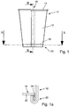
- the representation of the Fig. 1 shows a side view of a container according to the invention, which is designed here as a cup 10.
- the cup 10 has a frustoconical jacket 12 which is provided with a so-called lip curl 14 on its upper edge.
- the jacket 12 is wound from a flat segment, as it is for example in FIGS. 2 and 3 is shown. The longitudinal edges of this segment are placed on top of one another during winding, so that an overlap area 16 is formed.
- the jacket 12 has a frustoconical shape after winding.
- the cup 10 is provided with a closing element in the form of a base 18.
- the bottom 18 has an approximately pot-shaped design.
- the base 18 is formed from a, for example, circular disk-shaped paper segment, the edges of which are folded down by 90 ° or slightly more than 90 ° and thereby form a base collar 24 projecting approximately vertically downward from a base plate 22, see Fig. 1a .
- the lower end of the jacket 12 is turned over by 180 °.
- the jacket 12, which is turned around the base collar 24, and the base collar 24 are then first heated by means of hot air and then pressed together.
- the paper material of the base 18 and of the casing 12 is provided with a plastic coating, for example polyethylene, on at least one side.
- the thermoplastic plastic coating is heated and when the jacket 12 and base 18 are pressed, jacket 12 and base 18 are then sealed to one another in the area of the so-called frame 20.
- FIG. 11 shows a sectional view of the sectional plane BB of FIG Fig. 1 .
- the cutting plane BB is placed in the overlap region 16, in which the jacket 12 consists of two layers of material lying on top of one another.
- the base 18 has the base plate 22 and the base collar 24 which projects downwards approximately perpendicularly from the base plate 22.
- the lower end of the jacket 12 is wrapped around the base collar 24.
- two material layers of the flat segment from which the jacket 12 is formed lie one above the other on both the inside and the outside of the bottom collar 24.
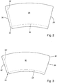
- Fig. 2 shows a plan view of a flat segment 26 for a cup 10 according to a first embodiment.
- the segment 26 is on a conical or frustoconical mandrel wound, so that the frustoconical shell 12 results.
- the segment 26 has a first side edge 28 and a second side edge 30.
- the side edge 30 goes to her in Fig. 2 lower end in a bevel 32 over.
- the bevel 32 serves to space the segment edge resting on the base collar 24 on the inside and the outside of the base collar 24 from one another in the circumferential direction.
- the jacket 26 is folded around the lower end of the base collar 24 approximately in the area of the dashed line 34.
- FIG. 3 shows a segment 36 for a cup according to the invention according to a further embodiment.
- a first side edge 38 has a bevel 40 at its upper end and a second side edge 42 is provided with a re-entrant corner 44 at its lower end.
- the re-entrant corner 44 serves to space the segment edge resting on the base collar 24 on the inside and the outside of the base collar 24 in the circumferential direction when the lower end of the jacket is turned over.
- the beveled end 40 of the first side edge 38 is used to ensure that the lip curl 14 can also be easily shaped in the overlapping area.
- the upper end of the casing 12 can also be turned over around a cover collar of a cover. This is done with containers according to the invention which are designed as cans. A cover would then be inserted exactly the other way around as the bottom 18 in the jacket, so that the cover collar protrudes upwards from a cover plate and the upper end of the jacket would then be folded around this cover collar by 180 ° and the cover collar and the upper folded-over end of the Mantle would then be pressed into a frame and sealed.
- the representation of the Fig. 4 shows a sectional view of the section plane AA in FIG Fig. 1 before pressing the frame 20.
- the section plane AA is shown in the overlap area 16.
- the jacket 12 is, see also Fig. 1a , wrapped around the end of the bottom collar 24 with its lower end.
- the second segment edge 30 rests on an outside of the bottom collar 24 and then runs through the bevel 32, not visible in FIG Fig. 4 , in the circumferential direction to the right. On the inside, the second segment edge 30 then rests on the inside of the floor collar 24 at a distance from the second segment edge 30 in the circumferential direction due to the bevel 32.
- the first segment edge 28 lies on the outside of the bottom collar 24 at a distance from the bottom collar 24 in the radial direction, and the first segment edge 28 is also at a distance from the bottom collar 24 on the inside of the bottom collar 24.
- the area of the segment which adjoins the first segment edge 28 has a stepped area 46, 48 both on the inside and on the outside of the bottom collar 24.
- This area 46 on the outside of the bottom collar 24 and also the area 48 on the inside of the bottom collar 24 are each arranged in the area of the second segment edge 30 and still belong to the overlap area.
- the overlap area 16 ends in Fig. 4 on the one hand at the first segment edge 28 and on the other hand at the second segment edge 30.
- an edge section of the overlap area includes the step-shaped area 46 and the cavity 50 in front of the second segment edge 30, in other words the edge section ends at the point or at the line, at which the step-shaped area 46 ends and the segment rests on the outside of the floor collar 24 again.
- a cavity 50 is located in the stepped region 46 in front of the second segment edge 30.
- This cavity 50 has an approximately triangular cross-section and is created by the step-shaped region 46.
- Fig. 4 shows the state of the frame 20 in the area of the overlap 16 before pressing and sealing.
- the cavity 50 is connected to the interior of the cup 10 before the pressing, since the second segment edge 30 extends into the interior of the cup 10.
- sealing material that is to say the melted PE coating of the material of the jacket 12 and / or of the base 18. If this does not succeed, the cavity 50 represents a potential leak point via which liquid can then get from the interior of the cup 10 into the area of the frame 20.
- Fig. 4 shows a conventional press ram 54 on the radially inner side of the frame 20.
- This conventional press ram 54 is radially outward, in Fig. 4 so moved down to crimp and seal the frame 20.
- a plurality of circular segment-shaped press punches 54 are provided, which are arranged on the inside of the frame 20 and then moved radially outward. Nevertheless, the liquid-tight design of the frame 20 is problematic.
- Fig. 5 shows a in the area of the frame 20 of the illustration of FIG Fig. 4 corresponding representation of the jacket 12 and the bottom collar 24. The jacket 12 and the bottom collar 24 are therefore not explained again.
- This press ram 56 has a radially outwardly protruding projection 58 which protrudes radially outward relative to the remaining press surface 60 of the press ram 56.
- This projection 58 is arranged and dimensioned in such a way that it applies an increased pressure to the overlap 16 in the edge section, i.e. in the area of the cavity 50 in front of the second segment edge 30 on the outside of the base collar 24. In this way, after the frame 20 has been pressed and sealed, it can be ensured that the cavity 50 is significantly smaller than in conventional cups and is in any case completely filled with sealing material.
- FIG. 6 The state after pressing the frame is shown in the illustration of Fig. 6 .
- the frame 20 is in the not yet pressed state Fig. 5 warmed, for example subjected to hot air from the underside.
- a radially outwardly directed pressing pressure is then exerted on the frame 20, which in FIG Fig. 6 is symbolized by the arrow 62.
- a pressing pressure directed outward in the radial direction is exerted over the entire circumference of the frame by means of the press ram 56 or a plurality of press rams 56.
- Fig. 6 shows the already fully pressed and sealed state of the frame 20. It can be clearly seen that the cavity 50 is on the outside in front of the inner segment edge 30 of the bottom collar 24 is completely filled with sealing material, which in Fig. 6 is shown in black.
- the frame 20 Due to the increased pressing pressure in the area of the projection 58, the frame 20 has a recess 66 on its inside.
- the dimensions of the recess 66 correspond approximately to the dimensions of the projection 58.
- the ram 56 and thus the pressing surface 60 generally have a height which corresponds to the height of the frame on the inside of the frame 20.
- the pressing surface 60 can also be designed in the form of one or more strips, see Figure 5a . These strips can then each have a protrusion 58 which protrudes in the radial direction and the function of the protrusion 58 of the ram 56 in FIG Fig. 6 met as this in Figure 5a is shown. If necessary, it can also be sufficient to provide only one of the strips with a projection.
- FIG. 7 shows the cup in the area of the frame 20 with the ram 56 in the already pressed state of FIG Fig. 6 .
- the ram 56 and the frame 20 are therefore not explained again.
- a counterpart 70 is arranged on the outside of the frame 20 opposite the ram 56.
- the counterpart 70 has a concave shape, the radius of this concave shape approximately corresponding to the outer radius of the frame 20. When the frame 20 is pressed, this counterpart 70 absorbs the pressing pressure exerted by the press ram 56.
- the representation of the Fig. 8 shows the arrangement of the Fig. 7 , wherein instead of the counterpart 70 a counterpart 72 is shown, which has a recess 74 on its side facing the frame 20.
- the recess 74 is approximately as wide as the overlap area 16 on the outside of the frame 20, which is shown in FIG Fig. 8 is down.
- the overlap area 16 can be received in the counterpart 72 through the recess 74 and the increased pressing pressure in the area of the arrow 62 can be concentrated on the area of the cavity 50.
- the recess 74 has rounded side edges so that damage to the outside of the frame 20 is avoided.
- the recess 74 has a depth which corresponds approximately to the material thickness of the segment 26 for producing the outer jacket 12. Thereby a secure pressing and sealing can be achieved in the area of the cavity 50 without the risk of the material of the jacket 12 being damaged in the area of the overlap 16 by excessive pressure.
- the representation of the Fig. 9 shows a further embodiment of a container according to the invention.
- the representation of the Fig. 9 represents one of the Fig. 4 corresponding partial sectional view, the cutting plane being the same as the cutting plane AA in FIG Fig. 1 was placed through the frame 20.
- the ram 56 has already been explained and has the projection 58.
- the coat 74 of the Fig. 9 formed from a segment, the second segment edge 30 of which is provided with a sealing strip 76.
- the sealing strip 76 consists of a sealable thermoplastic material, for example polyethylene.
- the sealing strip 76 is wrapped around the second segment edge 30 so that the sealing strip extends a little way along the overlap region 16 on both sides of the segment edge 30.
- additional thermoplastic material is available when the frame 20 is pressed in order to completely fill the cavity 50 in front of the inner segment edge 30, which rests on the outside of the bottom collar 24, with sealing material, in this case polyethylene.
- the provision of the sealing strip 76 thereby enables an even more reliable sealing of the frame 20 with respect to the interior of the container according to the invention.
- the sealing strip 76 can prevent the open cut edge on the segment edge 30 from coming into contact with liquid within the Container comes.
- the sealing strip 76 is therefore preferably used in cans made of paper material or paper-like material that are intended to be filled with liquid as cups over a longer period of time.
- the jacket 74 would not only be connected to the base collar 24 by means of the frame 20, but, as already explained at the beginning, would also be connected in a liquid-tight manner to a pot-shaped lid by means of a further frame.
- the inner segment edge 30 is then provided with the sealing strip 76 in order to achieve a particularly liquid-tight design of the frame in the area of the cover.
Description
- Die Erfindung betrifft eine Vorrichtung und ein Verfahren zum Herstellen von Behältern aus Papiermaterial oder papierähnlichem Material sowie einen mehrteiligen Behälter aus Papiermaterial oder papierähnlichem Material. Eine Vorrichtung zum Herstellen von Behältern aus Papiermaterial oder papierähnlichem Material, wobei der Behälter einen Mantel aus einem gewickelten flächigen Segment, dessen an den Längsseiten angeordnete Segmentkanten überlappen und dadurch einen Überlappungsbereich bilden, und ein topfartiges Abschlusselement, nämlich einen topfartigen Boden und/oder einen topfartigen Deckel, aufweist, wobei der Mantel und das Abschlusselement mittels einer Zarge im Wesentlichen flüssigkeitsdicht miteinander verbunden sind, weist zum Verpressen und Versiegeln der Zarge wenigstens einen Pressstempel auf, der die Zarge mit im Wesentlichen radial gerichtetem Pressdruck beaufschlagt.
- Als Papiermaterial oder papierähnliches Material wird dabei beispielsweise Papier, Karton oder Pappe oder auch flächig vorliegende Kunststoffmaterialien, auch Kunststofflaminate bezeichnet. Beispielsweise kann Papier, Karton oder Pappe in flächigen Segmenten vorliegen und diese flächigen Segmente können dann einerseits zu einer konischen Hülse gewickelt und andererseits zu einem topfförmigen Boden verformt werden. Zweckmäßigerweise ist das Papiermaterial flüssigkeitsdicht beschichtet. In gleicher Weise oder zumindest ähnlicher Weise wie Papiermaterial werden auch flächig vorliegende Kunststoffmaterialien zu Bechern verarbeitet. Flächige Kunststoffmaterialien sind beispielsweise auch Kunststofflaminate. Dabei wird das flächige Kunststoffmaterial, das in Segmentform vorliegt, ebenfalls um einen Wickeldorn gewickelt und im Bereich der Überlappung verbunden, um eine konische Hülse zu formen. Auch ein topfförmiger Boden oder topfförmiger Deckel kann aus dem flächigen Kunststoffmaterial geformt werden, indem ein kreisförmiger Zuschnitt in seinem Randbereich gegenüber einer Bodenfläche oder Deckelfläche etwa senkrecht nach oben geklappt wird. Die Probleme, die bei papierähnlich zu verarbeitendem Kunststoffmaterial auftreten, sind dabei im Wesentlichen die gleichen, die beim Verarbeiten von Papiermaterial auftreten. Die vorliegende Erfindung kann für papierähnlich zu verarbeitende Kunststoffmaterialien eingesetzt werden, sie ist aber nicht speziell für papierähnlich zu verarbeitende Kunststoffmaterialien ausgebildet, sondern kann vielmehr mit erheblichen Vorteilen auch für Papiermaterial eingesetzt werden. Aus der US-Patentschrift
US 4,571,233 ist ein Pressstempel für das Verpressen einer Zarge eines Behälters aus Papiermaterial bekannt. Der Pressstempel weist auf seiner Umfangsfläche, die von einer Innenseite der Zarge her gegen diese gedrückt wird, parallel zur Längsachse des Behälters verlaufende Rillen auf. Der Abstand der Rillen zueinander in Umfangsrichtung ist dabei wesentlich geringer als eine Breite des Überlappungsbereichs des Mantels des Behälters. - Aus der US-Offenlegungsschrift
US 2007/0137030 A1 ist ein weiterer Pressstempel zum Verpressen der Zarge eines Behälters aus Papiermaterial bekannt. Der Pressstempel wird von der Innenseite der Zarge her gegen diese gedrückt und weist in Umfangsrichtung laufende Rillen auf. Der Pressstempel ist aus insgesamt vier Segmenten gebildet, die jeweils einen Winkelbereich von 90° abdecken. - Aus der deutschen Offenlegungsschrift
DE 10 2014 210 960 A1 ist ein Pressstempel zum Verpressen des Überlappungsbereichs einer konischen Hülse bekannt. Die konische Hülse wird später als Mantel eines Bechers eingesetzt und hierzu dann mit einem topfförmigen Boden verbunden. Der Pressstempel weist an seinen beiden Enden jeweils einen Vorsprung auf, um am unteren Ende der Hülse und am oberen Ende der Hülse den Überlappungsbereich stärker zusammenzudrücken als in einem Mittenbereich. - Mit der Erfindung sollen eine Vorrichtung und ein Verfahren zum Herstellen von Behältern aus Papiermaterial oder papierähnlichem Material und ein mehrteiliger Behälter aus Papiermaterial oder papierähnlichem Material hinsichtlich der Dichtheit der Zarge verbessert werden.
- Erfindungsgemäß ist hierzu eine Vorrichtung zum Herstellen von Behältern aus Papiermaterial oder papierähnlichem Material mit den Merkmalen von Anspruch 1 vorgesehen. Der Pressstempel weist in einem für die Beaufschlagung eines Randabschnitts des Überlappungsbereichs des Mantels an der Zarge vorgesehenen Abschnitt einen in radialer Richtung vorragenden Vorsprung auf. Der Überlappungsbereich hat einen Randabschnitt, der durch diejenige Segmentkante des flächigen Segments, die durch das flächige Segment abgedeckt ist, und einen kleinen Bereich vor und hinter dieser Segmentkante definiert ist, gesehen in Umfangsrichtung der Hülse. Dieser Randabschnitt des Überlappungsbereichs erstreckt sich zumindest von der unteren oder abgedeckten Segmentkante, die durch das auf der Segmentkante aufliegende Segment abgedeckt ist, bis zu einem Bereich, in dem das flächige Segment, das auf der unteren Segmentkante aufliegt, wieder auf derselben Höhe wie die untere Segmentkante angeordnet ist. Folglich enthält dieser Randabschnitt des Überlappungsbereichs auch einen kleinen stufenförmigen Abschnitt außerhalb des Überlappungsbereiches.
- Mittels eines in radialer Richtung vorragenden Vorsprungs kann der Überlappungsbereich abschnittsweise mit einem erhöhten Pressdruck beaufschlagt werden und es kann dadurch erreicht werden, dass auch im Überlappungsbereich keine Hohlräume innerhalb der verpressten Zarge vorhanden sind. Es wurde festgestellt, dass bei konventionell hergestellten mehrteiligen Behältern gerade die Randbereiche des Überlappungsbereichs im Bereich der Zarge für Undichtheiten sorgen. Dies deshalb, da an der Segmentkante, die auf der Außenseite des Abschlusselements, beispielsweise des Bodenkragens des Bodens oder des Deckelkragens eines Deckels, aufliegt, zwangsläufig durch die innenliegende Segmentkante und das darüber liegende Segment ein Hohlraum entsteht. Bei konventionellen Vorrichtungen und Verfahren sowie bei konventionellen Behältern wird dieser Hohlraum beim Verpressen der Zarge nicht vollständig aufgefüllt. Dieser Hohlraum kann eine Verbindung zum Innenraum des Bechers haben, so dass dann eine Leckstelle gebildet ist. Durch die erfindungsgemäße Vorrichtung wird die Zarge im Bereich einer oder auch beider Segmentkanten des Überlappungsbereichs so stark zusammengedrückt, dass der vor dem Verpressen noch vorhandene Hohlraum an der Segmentkante vollständig mit Siegelmaterial ausgefüllt ist. Bevorzugt wird lediglich der Randabschnitt des Überlappungsbereichs mit erhöhtem Pressdruck beaufschlagt, in dem die innenliegende Segmentkante, die auch vom Innenraum des Behälters zugänglich ist, auf der Außenseite des Abschlusselements aufliegt. Die Zarge ist dadurch auch im Überlappungsbereich vollständig flüssigkeitsdicht. Der in radialer Richtung vorragende Vorsprung ist dabei in der Regel an einer im Querschnitt kreisabschnittsförmigen Pressfläche vorgesehen, über die der Vorsprung dann in radialer Richtung hinausragt. Die Höhe der Pressfläche entspricht in der Regel der Höhe der Zarge. Die Pressfläche kann auch auf mehrere kreisabschnittsförmige Leisten aufgeteilt sein, die dann entweder alle oder auch nur einige einen Vorsprung aufweisen, der in radialer Richtung vorragt. Die durch einen solchen Pressstempel dann erzeugte Vertiefung auf der Innenseite der Zarge ist rillenförmig und über die Höhe der Zarge können mehrere Rillen eingeprägt sein. Bei solchen rillenförmigen Einprägungen ist dann wesentlich, dass im Bereich der eingeprägten Rillen kein Hohlraum mehr an der innenliegenden Segmentkante vorliegt. Wenn zwischen den rillenförmigen Einprägungen noch Hohlräume vorhanden sind, spielt dies für die Dichtheit der Zarge keine Rolle mehr.
- In Weiterbildung der Erfindung ist der Pressstempel auf einer radial innenliegenden Seite der Zarge angeordnet und der Vorsprung ragt in radialer Richtung nach außen vor. Insbesondere ist die durch den Vorsprung auf dem Pressstempel eingeprägte Vertiefung auf der schlecht sichtbaren Innenseite der Zarge angeordnet.
- Die Anordnung des Pressstempels mit dem wenigstens einen Vorsprung auf einer radial innenliegenden Seite der Zarge hat sich als vorteilhaft herausgestellt.
- In Weiterbildung der Erfindung ist eine in radialer Richtung außenliegende Oberfläche des Vorsprungs konvex gekrümmt.
- Die konvexe Krümmung kann einer Krümmung der Innenseite der Zarge angepasst sein, so dass die Krümmung des Vorsprungs im Wesentlichen dem Krümmungsradius der Zarge entspricht. Dadurch kann über die Breite des Vorsprungs gesehen ein gleichmäßiger Pressdruck erzeugt werden.
- In Weiterbildung der Erfindung ragt der Vorsprung in radialer Richtung um eine Höhe über die übrige Oberfläche des Pressstempels vor, die zwischen dem 0,5-Fachen und dem 1,5-Fachen, insbesondere dem 1-Fachen, der Dicke des flächigen Segments für den Mantel beträgt.
- Auf diese Weise kann ein erhöhter Pressdruck eingebracht werden, ohne dass zu befürchten wäre, dass der Pressstempel das Material des Mantels, auf das der Pressdruck ausgeübt wird, beschädigt. Bei zu hohem Pressdruck könnte der Pressstempel gegebenenfalls das Material beschädigen, wodurch dann wiederum Undichtigkeiten hervorgerufen werden könnten.
- In Weiterbildung der Erfindung erstreckt sich der Vorsprung in Umfangsrichtung über eine Breite, die zwischen dem 0,25-Fachen und dem 0,75-Fachen, insbesondere dem 0,5-Fachen, der Breite des Überlappungsbereichs in Umfangsrichtung beträgt.
- Es hat sich als vorteilhaft herausgestellt, den erhöhten Pressdruck nicht über die gesamte Breite des Überlappungsbereichs, sondern nur über einen Teil der Breite des Überlappungsbereichs im Bereich einer oder beider Segmentkanten des Überlappungsbereichs aufzubringen. Der Absolutbetrag des Pressdrucks kann dadurch geringer gewählt werden und dennoch kann eine ausreichende Dichtheit erzielt werden.
- In Weiterbildung der Erfindung ist der Vorsprung in Umfangsrichtung so zu dem Überlappungsbereich angeordnet, dass nur eine der Segmentkanten des Mantels im Überlappungsbereich mit einem erhöhten Pressdruck beaufschlagt wird.
- Um eine vollständige gründliche Abdichtung der Zarge im Überlappungsbereich zu erzielen, genügt es, lediglich eine der Segmentkanten am Rand des Überlappungsbereichs mit erhöhtem Pressdruck zu beaufschlagen. Vorteilhafterweise wird dabei die innere und am Abschlusselement anliegende Segmentkante des Überlappungsbereichs gewählt. Diese innenliegende und am Abschlusselement anliegende Segmentkante erstreckt sich in den Innenraum des Behälters hinein und ein Hohlraum vor dieser Segmentkante kann daher zum Eindringen von im Behälter enthaltener Flüssigkeit in die Zarge führen.
- Vorteilhafterweise ist der Vorsprung symmetrisch zu einem Rand des Überlappungsbereichs angeordnet.
- Auf diese Weise kann eine zuverlässige Verpressung im Bereich dieser Segmentkante erzielt werden und es kann vor allem erreicht werden, dass ein Hohlraum vor dieser Segmentkante beim Verpressen vollständig mit Siegelmaterial gefüllt wird. Der Randabschnitt des Überlappungsbereichs wird dabei nicht nur durch die innenliegende Segmentkante definiert sondern durch die Stelle, an der der auf der innenliegenden Segmentkante aufliegende Segmentabschnitt wieder in Kontakt mit dem Abschlusselement kommt. Bei noch nicht verpresster Zarge ist das das Ende des Hohlraums vor der innenliegenden Segmentkante.
- Der Vorsprung ist bevorzugt so angeordnet, dass er die auf der Außenseite des Abschlusselements anliegende Segmentkante des Überlappungsbereichs beaufschlagt. Die auf der Außenseite des Abschlusselements anliegende Segmentkante erstreckt sich in den Innenraum des Behälters hinein. Im Bereich dieser Segmentkante ist es daher besonders wichtig, dass vor der Segmentkante nach dem Verpressen der Zarge kein Hohlraum mehr vorhanden ist. Mit der symmetrischen Anordnung des Vorsprungs zu einem Rand des Überlappungsbereichs kann erreicht werden, dass der Hohlraum vor dieser Segmentkante beim Verpressen der Zarge vollständig mit Siegelmaterial gefüllt wird.
- In Weiterbildung der Erfindung liegt dem Pressstempel ein Gegenstück gegenüber, wobei die Zarge zwischen dem Gegenstück und dem Pressstempel aufgenommen wird und wobei das Gegenstück in dem Bereich, in dem der Überlappungsbereich zu liegen kommt, in anderen Worten in dem der Überlappungsbereich angeordnet ist, eine Vertiefung aufweist.
- Mittels einer Vertiefung können Beschädigungen durch einen zu hohen oder ungleichmäßigen Pressdruck verhindert werden.
- In Weiterbildung der Erfindung beträgt eine Breite der Vertiefung in Umfangsrichtung das 0,5-Fache bis 1,5-Fache der Breite des Überlappungsbereichs.
- Dadurch wird ein zu hoher Pressdruck gerade im Überlappungsbereich, in dem ja gegenüber dem übrigen Außenmantel mehr Materialschichten aufeinanderliegen, vermieden. Die Vertiefung kann ausgerundete Seitenkanten aufweisen, um Druckstellen und Beschädigungen des Materials im Bereich der Zarge zu vermeiden. Wenn die Vertiefung weniger als das 1-Fache der Breite des Überlappungsbereichs beträgt, wird die Vertiefung in der Regel nicht gegenüber dem Vorsprung angeordnet.
- In Weiterbildung der Erfindung beträgt eine Tiefe der Vertiefung das 0,75-Fache bis 1,25-Fache, insbesondere das 1-Fache, der Dicke des flächigen Segments für den Mantel. Erfindungsgemäß ist auch ein Verfahren zum Herstellen eines Behälters aus Papiermaterial oder papierähnlichem Material mit den Merkmalen des Anspruchs 9 vorgesehen. Das Verfahren weist folgende Schritte auf: Wickeln eines flächigen Segments zu einem Mantel, so dass sich die an den Längsseiten angeordneten Segmentkanten überlappen und dadurch einen Überlappungsbereich bilden, Verbinden eines topfartigen Abschlusselements, nämlich ein topfartiger Boden und/oder ein topfartiger Deckels, mit dem Mantel mittels einer Zarge, so dass der Mantel und das Abschlusselement im Wesentlichen flüssigkeitsdicht miteinander verbunden sind, Verpressen und Versiegeln des Mantels und des Abschlusselements im Bereich der Zarge mit wenigstens einem Pressstempel, wobei die Zarge mit im Wesentlichen radial gerichtetem Pressdruck beaufschlagt wird, und Beaufschlagen wenigstens eines Randabschnitts des Überlappungsbereichs des Mantels im Bereich der Zarge mit einem im Vergleich zu der übrigen Zarge erhöhten Pressdruck.
- Durch Aufbringen eines erhöhten Pressdrucks in wenigstens einem Randabschnitt des Überlappungsbereichs beim Verpressen und Versiegeln der Zarge können Leckstellen sicher vermieden werden.
- In Weiterbildung der Erfindung ist das Aufbringen des erhöhten Pressdrucks mittels eines in radialer Richtung vorragenden Vorsprungs an dem Pressstempel vorgesehen.
- Der Vorsprung ragt aus der übrigen Pressfläche des Stempels vor. Die Pressfläche kann auch mittels mehrerer leistenförmiger Vorsprünge gebildet sein, die dann alle oder auch nur teilweise einen in radialer Richtung vorragenden Vorsprung aufweisen. Die Pressfläche kann im Querschnitt beispielsweise kreisabschnittsförmig sein, wobei der Vorsprung dann aus dieser kreisabschnittsförmigen Pressfläche vorragt.
- In Weiterbildung der Erfindung ist das Beaufschlagen eines Bereichs auf der Innenseite der Zarge mit dem erhöhten Pressdruck vorgesehen, der der innenliegenden Segmentkante des Mantels, die auf der Außenseite des Abschlusselements aufliegt, gegenüberliegt.
- Diese innenliegende Segmentkante, die auf der Außenseite des Abschlusselements aufliegt, erstreckt sich in ihrem weiteren Verlauf in den Innenraum des Behälters hinein und kommt damit mit einer gegebenenfalls im Behälter befindlichen Flüssigkeit in Berührung. Wenn nun erfindungsgemäß diese innenliegende Segmentkante mit dem erhöhtem Pressdruck beaufschlagt wird, können Hohlräume und damit Leckstellen in diesem Bereich sicher vermieden werden.
- In Weiterbildung der Erfindung ist der Bereich, der mit erhöhtem Pressdruck beaufschlagt wird, symmetrisch zu dem Rand des Überlappungsbereichs angeordnet, an dem die innenliegende Segmentkante des Mantels, die auf der Außenseite des Abschlusselements aufliegt, angeordnet ist.
- Auf diese Weise kann ein sicheres Verpressen erreicht werden und speziell kann erreicht werden, dass ein Hohlraum, der vor der innenliegenden Segmentkante des Mantels gebildet ist, beim Verpressen vollständig mit Siegelmaterial gefüllt wird.
- In Weiterbildung der Erfindung ist das Beaufschlagen eines Bereichs der Zarge mit dem erhöhten Pressdruck vorgesehen, dessen Breite dem 0,25-Fachen bis 0,75-Fachen, insbesondere dem 0,5-Fachen, der Breite des Überlappungsbereichs beträgt.
- Indem damit nur ein Teil der Breite des Überlappungsbereichs mit dem erhöhten Pressdruck beaufschlagt wird, kann der Absolutwert der Presskraft kleiner gewählt werden und dennoch wird eine mit Sicherheit flüssigkeitsdichte Verpressung der Zarge ermöglicht.
- Gemäß der Erfindung ist auch ein mehrteiliger Behälter aus Papiermaterial oder papierähnlichem Material mit den Merkmalen des Anspruchs 14 vorgesehen. Der mehrteilige Behälter besteht aus einem Mantel, der aus einem gewickelten flächigen Segment, dessen seitliche Segmentkanten im gewickelten Zustand in einem Überlappungsbereich angeordnet sind, gebildet ist, und weist ein topfartiges Abschlusselement, nämlich ein topfartiger Boden und/oder ein topfartiger Deckel, auf, wobei der Mantel und das Abschlusselement mittels einer Zarge im Wesentlichen flüssigkeitsdicht verbunden sind, wobei im Bereich der Zarge der Mantel und das Abschlusselement miteinander verpresst und versiegelt sind, bei dem in einem Randabschnitt des Überlappungsbereichs ein Zwischenraum, der zwischen der auf der Außenseite des Abschlusselements aufliegenden Segmentkante und dem auf der Segmentkante aufliegenden Abschnitt des Segments des Mantels gebildet ist, vollständig mit einem Siegelmaterial ausgefüllt ist und bei dem auf der Innenseite der Zarge im Bereich gegenüber der Segmentkante, die auf der Außenseite des Abschlusselements aufliegt, eine eingepresste Vertiefung vorgesehen ist.
- Indem dieser Zwischenraum, der vor dem Verpressen der Zarge in der Regel eine Verbindung mit dem Innenraum des Bechers aufweist, im Bereich der Zarge vollständig mit einem Siegelmaterial ausgefüllt ist, kann sicher erreicht werden, dass im Bereich dieser Segmentkante keine Flüssigkeit aus dem Innenraum des Behälters in die Zarge eintritt. Dass dieser Zwischenraum vollständig mit Siegelmaterial gefüllt ist, wird durch einen erhöhten Pressdruck in diesem Bereich sichergestellt, der zu einer eingepressten Vertiefung auf der Innenseite der Zarge führt.
- In Weiterbildung der Erfindung beträgt eine Breite der Vertiefung in Umfangsrichtung zwischen dem 0,25-Fachen und dem 0,75-Fachen, insbesondere dem 0,5-Fachen, der Breite des Überlappungsbereichs.
- In Weiterbildung der Erfindung beträgt eine Tiefe der Vertiefung das 0,5-Fache bis 1-Fache der Materialdicke des Segments des Mantels.
- In Weiterbildung der Erfindung ist die Vertiefung symmetrisch zum Rand des Überlappungsbereichs, an dem die innenliegende Segmentkante angeordnet ist, die auf der Außenseite des Abschlusselements aufliegt, angeordnet.
- Weitere Merkmale und Vorteile der Erfindung ergeben sich aus den Ansprüchen und der folgenden Beschreibung bevorzugter Ausführungsformen der Erfindung im Zusammenhang mit den Zeichnungen. Einzelmerkmale der unterschiedlichen, dargestellten Ausführungsformen können dabei in beliebiger Weise miteinander kombiniert werden, ohne den Rahmen der Erfindung zu überschreiten. In den Zeichnungen zeigen:
- Fig. 1
- einen erfindungsgemäßen Becher in einer Seitenansicht,
- Fig. 1a
- eine abschnittsweise Schnittansicht auf die Schnittebene B-B in
Fig. 1 , - Fig. 2
- eine Draufsicht auf ein flächiges Segment gemäß einer ersten Ausführungsform zum Wickeln eines Mantels,
- Fig. 3
- ein flächiges Segment gemäß einer zweiten Ausführungsform zum Wickeln eines Mantels,
- Fig. 4
- eine abschnittsweise Ansicht auf die Schnittebene A-A in
Fig. 1 mit einem Pressstempel nach dem Stand der Technik vor dem Verpressen der Zarge, - Fig. 5
- eine teilweise Ansicht der Schnittansicht A-A der
Fig. 1 mit einem erfindungsgemäßen Pressstempel vor dem Verpressen der Zarge, - Fig. 5a
- eine abschnittsweise Ansicht des Pressstempels der
Fig. 5 von schräg oben, - Fig. 6
- die Schnittansicht der
Fig. 5 nach dem Verpressen der Zarge und somit am fertiggestellten Becher, - Fig. 7
- die Schnittansicht der
Fig. 6 , wobei gestrichelt ein Gegenstück eingezeichnet ist, das auf der Außenseite der Zarge anliegt, - Fig. 8
- die Schnittansicht der
Fig. 6 , wobei ein Gegenstück gemäß einer weiteren Ausführungsform der Erfindung eingezeichnet ist und - Fig. 9
- eine Schnittansicht eines Behälters gemäß einer weiteren Ausführungsform, wobei eine Schnittebene in die Schnittebene A-A in
Fig. 1 gelegt ist. - Die Darstellung der
Fig. 1 zeigt in einer Seitenansicht einen erfindungsgemäßen Behälter, der hier als Becher 10 ausgebildet ist. Der Becher 10 weist einen kegelstumpfförmigen Mantel 12 auf, der an seinem oberen Rand mit einer sogenannten Mundrolle 14 versehen ist. Der Mantel 12 ist aus einem flächigen Segment gewickelt, wie es beispielsweise inFig. 2 und Fig. 3 dargestellt ist. Die Längskanten dieses Segments werden beim Wickeln übereinandergelegt, so dass ein Überlappungsbereich 16 gebildet wird. Der Mantel 12 weist nach dem Wickeln eine kegelstumpfartige Form auf. - An seinem unteren Ende ist der Becher 10 mit einem Abschlusselement in Form eines Bodens 18 versehen. Der Boden 18 weist eine etwa topfförmige Gestaltung auf. Der Boden 18 wird aus einem beispielsweise kreisscheibenförmigen Papiersegment gebildet, dessen Ränder um 90° oder etwas mehr als 90° nach unten geklappt werden und dadurch einen von einer Bodenplatte 22 etwa senkrecht nach unten abragenden Bodenkragen 24 bilden, siehe
Fig. 1a . - Um diesen Bodenkragen 24 des Bodens 18 wird das untere Ende des Mantels 12 um 180° umgeschlagen. Der um den Bodenkragen 24 umgeschlagene Mantel 12 und der Bodenkragen 24 werden dann zunächst mittels Heißluft angewärmt und dann miteinander verpresst. Das Papiermaterial des Bodens 18 und des Mantels 12 ist wenigstens einseitig mit einer Kunststoffbeschichtung, beispielsweise Polyethylen, versehen. Die thermoplastische Kunststoffbeschichtung wird erwärmt und beim Verpressen von Mantel 12 und Boden 18 werden Mantel 12 und Boden 18 dann im Bereich der sogenannten Zarge 20 miteinander versiegelt. Dies geschieht dadurch, dass die erwärmten Polyethylenbeschichtungen oder Beschichtungen aus sonst einem geeigneten thermoplastischen Kunststoff miteinander verschmelzen und dadurch den Mantel 12 und den Boden 18 im Bereich des Bodenkragens 24 oder besser im Bereich der Zarge 20 im Wesentlichen flüssigkeitsdicht miteinander verbinden.
-
Fig. 1a zeigt eine abschnittsweise Schnittansicht auf die Schnittebene B-B derFig. 1 . Die Schnittebene B-B ist dabei in den Überlappungsbereich 16 gelegt, in dem also der Mantel 12 aus zwei aufeinanderliegenden Materialschichten besteht. Es ist gut zu erkennen, dass der Boden 18 die Bodenplatte 22 und den etwa senkrecht von der Bodenplatte 22 nach unten abragenden Bodenkragen 24 aufweist. Um den Bodenkragen 24 ist das untere Ende des Mantels 12 herumgeschlagen. Im Bereich der Überlappung 16 liegen dabei sowohl auf der Innenseite als auch der Außenseite des Bodenkragens 24 zwei Materiallagen des flächigen Segments, aus dem der Mantel 12 gebildet ist, übereinander. -
Fig. 2 zeigt eine Draufsicht auf ein flächiges Segment 26 für einen Bechers 10 gemäß einer ersten Ausführungsform. Das Segment 26 wird auf einen kegelförmigen oder kegelstumpfförmigen Dorn gewickelt, so dass sich der kegelstumpfförmige Mantel 12 ergibt. Das Segment 26 weist eine erste Seitenkante 28 und eine zweite Seitenkante 30 auf. Beim Wickeln des Segments 26 wird eine Überlappung gebildet, so dass dann die erste Seitenkante 28 an die inFig. 2 gestrichelt eingezeichnete Position 28' gelangt. Die Seitenkante 30 geht an ihrem inFig. 2 unteren Ende in eine Abschrägung 32 über. Die Abschrägung 32 dient dazu, die auf dem Bodenkragen 24 aufliegende Segmentkante auf der Innenseite und der Außenseite des Bodenkragens 24 in Umfangsrichtung voneinander zu beabstanden. Der Mantel 26 wird dabei etwa im Bereich der gestrichelten Linie 34 um das untere Ende des Bodenkragens 24 umgeschlagen. - Die Darstellung der
Fig. 3 zeigt ein Segment 36 für einen erfindungsgemäßen Becher gemäß einer weiteren Ausführungsform. Eine erste Seitenkante 38 weist dabei an ihrem oberen Ende eine Abschrägung 40 auf und eine zweite Seitenkante 42 ist an ihrem unteren Ende mit einer einspringenden Ecke 44 versehen. Die einspringende Ecke 44 dient dazu, beim Umschlagen des unteren Endes des Mantels die auf dem Bodenkragen 24 aufliegende Segmentkante auf der Innenseite und der Außenseite des Bodenkragens 24 in Umfangsrichtung voneinander zu beabstanden. In ähnlicher Weise dient das abgeschrägte Ende 40 der ersten Seitenkante 38 dazu, dass sich auch im Überlappungsbereich die Mundrolle 14 problemlos ausformen lässt. - Anstelle der Ausbildung einer Mundrolle 14 kann das obere Ende des Mantels 12 auch um einen Deckelkragen eines Deckels umgeschlagen werden. Dies wird bei erfindungsgemäßen Behältern gemacht, die als Dosen ausgebildet sind. Ein Deckel würde dann genau umgekehrt wie der Boden 18 in den Mantel eingesetzt, so dass also der Deckelkragen von einer Deckelplatte nach oben abragt und das obere Ende des Mantels würde dann um 180° um diesen Deckelkragen herumgeschlagen und der Deckelkragen und das obere umgeschlagene Ende des Mantels würden dann zu einer Zarge verpresst und versiegelt.
- Die Darstellung der
Fig. 4 zeigt eine abschnittsweise Ansicht auf die Schnittebene A-A inFig. 1 vor dem Verpressen der Zarge 20. Dargestellt ist die Schnittebene A-A im Überlappungsbereich 16. Der Mantel 12 ist, siehe auchFig. 1a , mit seinem unteren Ende um das Ende des Bodenkragens 24 herumgeschlagen. Die zweite Segmentkante 30 liegt auf einer Außenseite des Bodenkragens 24 auf und verläuft durch die Schräge 32 dann, nicht sichtbar in derFig. 4 , in Umfangsrichtung nach rechts. Auf der Innenseite liegt die zweite Segmentkante 30 aufgrund der Schräge 32 dann in Umfangsrichtung beabstandet von der zweite Segmentkante 30 auf der Innenseite des Bodenkragens 24 an. - Die erste Segmentkante 28 liegt auf der Außenseite des Bodenkragens 24 in radialer Richtung beabstandet vom Bodenkragen 24 und auch auf der Innenseite des Bodenkragens 24 ist die erste Segmentkante 28 vom Bodenkragen 24 beabstandet. Sowohl auf der Innenseite als auch der Außenseite des Bodenkragens 24 weist der Bereich des Segments, der sich an die erste Segmentkante 28 anschließt, einen stufenförmigen Bereich 46, 48auf. Dieser Bereich 46 auf der Außenseite des Bodenkragens 24 und auch der Bereich 48 auf der Innenseite des Bodenkragens 24 sind jeweils im Bereich der zweiten Segmentkante 30 angeordnet und gehören noch zum Überlappungsbereich. Der Überlappungsbereich 16 endet in
Fig. 4 einerseits an der ersten Segmentkante 28 und andererseits an der zweiten Segmentkante 30. Ein Randabschnitt des Überlappungsbereichs schließt jedoch den stufenförmigen Bereich 46 und den Hohlraum 50 vor der zweiten Segmentkante 30 ein, mit anderen Worten endet der Randabschnitt also an der Stelle oder an der Linie, an der der stufenförmige Bereich 46 endet und das Segment wieder auf der Außenseite des Bodenkragens 24 aufliegt. - Es ist in der Darstellung der
Fig. 4 gut zu erkennen, dass im stufenförmigen Bereich 46 vor der zweiten Segmentkante 30 ein Hohlraum 50 liegt. Dieser Hohlraum 50 hat einen etwa dreieckförmigen Querschnitt und entsteht durch den stufenförmigen Bereich 46. -
Fig. 4 zeigt den Zustand der Zarge 20 im Bereich der Überlappung 16 vor dem Verpressen und Versiegeln. Es ist dabei festzustellen, dass der Hohlraum 50 vor dem Verpressen mit dem Innenraum des Bechers 10 in Verbindung steht, da sich die zweite Segmentkante 30 bis in den Innenraum des Bechers 10 erstreckt. Beim Verpressen wird versucht, diesen Hohlraum 50 entweder zusammenzudrücken oder vollständig mit Siegelmaterial, also der aufgeschmolzenen PE-Beschichtung des Materials des Mantels 12 und/oder des Bodens 18 zu füllen. Gelingt dies nicht, so stellt der Hohlraum 50 eine potenzielle Leckstelle dar, über die dann Flüssigkeit aus dem Innenraum des Bechers 10 in den Bereich der Zarge 20 gelangen kann. - Auf der innenliegenden Seite des Bodenkragens 24 liegt vor der innenliegenden Segmentkante 30, 32 ebenfalls ein etwa dreieckförmiger Hohlraum 52. Dieser Hohlraum ist weniger kritisch, da er auf der Innenseite der Zarge 20 liegt und im verpressten und versiegelten Zustand der Zarge 20 infolgedessen nicht mit dem Innenraum des Bechers 10 in Verbindung steht. Im nicht verpressten Zustand der
Fig. 4 gehen allerdings die Hohlräume 50, 52 ineinander über, da diese ja vor der innenliegenden Segmentkante 30, 32 liegen, die um den unteren Rand des Bodenkragens 24 herumgeschlagen ist, vgl. auchFig. 1a . -
Fig. 4 zeigt auf der radial innenliegenden Seite der Zarge 20 einen konventionellen Pressstempel 54. Dieser konventionelle Pressstempel 54 wird radial nach außen, inFig. 4 also nach unten bewegt, um die Zarge 20 zu verpressen und zu versiegeln. Üblicherweise sind mehrere kreissegmentförmige Pressstempel 54 vorgesehen, die auf der Innenseite der Zarge 20 angeordnet dann radial nach außen bewegt werden. Dennoch ist die flüssigkeitsdichte Ausbildung der Zarge 20 problematisch. -
Fig. 5 zeigt eine im Bereich der Zarge 20 der Darstellung derFig. 4 entsprechende Darstellung des Mantels 12 und des Bodenkragens 24. Der Mantel 12 und der Bodenkragen 24 werden daher nicht erneut erläutert. - Anstelle des Pressstempels 54 ist nun aber abschnittsweise ein erfindungsgemäßer Pressstempel 56 dargestellt. Dieser Pressstempel 56 weist einen radial nach außen vorragenden Vorsprung 58 auf, der gegenüber der übrigen Pressfläche 60 des Pressstempels 56 radial nach außen vorragt.
- Dieser Vorsprung 58 ist dabei so angeordnet und so bemessen, dass er die Überlappung 16 im Randabschnitt, also im Bereich des Hohlraums 50 vor der zweiten Segmentkante 30 auf der Außenseite des Bodenkragens 24 mit einem erhöhten Pressdruck beaufschlagt. Dadurch kann nach dem Verpressen und Versiegeln der Zarge 20 sichergestellt werden, dass der Hohlraum 50 wesentlich kleiner ist als bei konventionellen Bechern und in jedem Fall vollständig mit Siegelmaterial gefüllt ist.
- Den Zustand nach dem Verpressen der Zarge zeigt die Darstellung der
Fig. 6 . Wie bereits erläutert wurde, wird die Zarge 20 im noch nicht verpressten Zustand derFig. 5 angewärmt, beispielsweise von der Unterseite her mit Heißluft beaufschlagt. Mittels des Pressstempels 56 wird dann auf die Zarge 20 ein radial nach außen gerichteter Pressdruck ausgeübt, der inFig. 6 mittels des Pfeils 62 symbolisiert ist. Es ist dabei festzustellen, dass über den gesamten Umfang der Zarge ein in radialer Richtung nach außen gerichteter Pressdruck mittels des Pressstempels 56 oder mehrerer Pressstempel 56 ausgeübt wird. Aufgrund des Vorsprungs 58 des Pressstempels 56, der in radialer Richtung nach außen über die übrige Pressfläche 60 des Pressstempels 56 vorragt, ist der Pressdruck im Bereich des Vorsprungs 58 und damit im Bereich des Hohlraums 50 und des Randabschnitts des Überlappungsbereichs aber größer als im Bereich der übrigen Pressfläche 60. Zur Verdeutlichung sind in Umfangsrichtung neben dem Pfeil 62 etwas kürzere Pfeile 64 eingezeichnet, die den verringerten Pressdruck im Bereich der übrigen Pressfläche 60 des Pressstempels 56 symbolisieren sollen. -
Fig. 6 zeigt den bereits fertig verpressten und versiegelten Zustand der Zarge 20. Es ist gut zu erkennen, dass der Hohlraum 50 vor der innenliegenden Segmentkante 30 auf der Außenseite des Bodenkragens 24 vollständig mit Siegelmaterial gefüllt ist, das inFig. 6 schwarz dargestellt ist. Der Hohlraum 52 auf der Innenseite des Bodenkragens 24 vor der Segmentkante 30 im Bereich der Abschrägung 32 ist hingegen nicht vollständig mit Siegelmaterial gefüllt, da hier nur der geringere Pressdruck in radialer Richtung nach außen ausgeübt wurde. Wie bereits erwähnt wurde, ist dieser Hohlraum 52 aber für die Dichtheit des Bechers unkritisch. - Aufgrund des erhöhten Pressdrucks im Bereich des Vorsprungs 58 weist die Zarge 20 auf ihrer Innenseite eine Vertiefung 66 auf. Die Vertiefung 66 entspricht in ihren Abmessungen etwa den Abmessungen des Vorsprungs 58.
- Der Pressstempel 56 und damit die Pressfläche 60 weist in der Regel eine Höhe auf, die der Höhe der Zarge auf der Innenseite der Zarge 20 entspricht. Um den Pressdruck zu erhöhen, kann die Pressfläche 60 auch in Form eines oder mehrerer Leisten ausgebildet sein, siehe
Fig. 5a . Diese Leisten können dann jeweils einen Vorsprung 58 aufweisen, der in radialer Richtung vorragt und die Funktion des Vorsprungs 58 des Pressstempels 56 inFig. 6 erfüllt, wie dies inFig. 5a dargestellt ist. Gegebenenfalls kann es auch ausreichend sein, dann nur eine der Leisten mit einem Vorsprung zu versehen. - Die Darstellung der
Fig. 7 zeigt den Becher im Bereich der Zarge 20 mit dem Pressstempel 56 im bereits verpressten Zustand derFig. 6 . Pressstempel 56 und Zarge 20 werden daher nicht erneut erläutert. - Auf der Außenseite der Zarge 20 ist gegenüber dem Pressstempel 56 ein Gegenstück 70 angeordnet. Das Gegenstück 70 weist eine konkave Formgebung auf, wobei der Radius dieser konkaven Formgebung etwa dem Außenradius der Zarge 20 entspricht. Beim Verpressen der Zarge 20 nimmt dieses Gegenstück 70 den vom Pressstempel 56 ausgeübten Pressdruck auf.
- Die Darstellung der
Fig. 8 zeigt die Anordnung derFig. 7 , wobei anstelle des Gegenstücks 70 ein Gegenstück 72 dargestellt ist, das auf seiner, der Zarge 20 zugewandten Seite eine Vertiefung 74 aufweist. Die Vertiefung 74 ist etwa so breit wie der Überlappungsbereich 16 auf der Außenseite der Zarge 20, die inFig. 8 unten liegt. Durch die Vertiefung 74 kann der Überlappungsbereich 16 im Gegenstück 72 aufgenommen werden und der erhöhte Pressdruck im Bereich des Pfeils 62 kann auf den Bereich des Hohlraums 50 konzentriert werden. - Die Vertiefung 74 weist abgerundete Seitenkanten auf, so dass Beschädigungen auf der Außenseite der Zarge 20 vermieden werden. Die Vertiefung 74 weist eine Tiefe auf, die etwa der Materialdicke des Segments 26 zur Herstellung des Außenmantels 12 entspricht. Dadurch kann eine sichere Verpressung und Versiegelung im Bereich des Hohlraums 50 erreicht werden, ohne dass die Gefahr besteht, dass das Material des Mantels 12 im Bereich der Überlappung 16 durch übermäßigen Pressdruck beschädigt wird.
- Die Darstellung der
Fig. 9 zeigt eine weitere Ausführungsform eines erfindungsgemäßen Behälters. Die Darstellung derFig. 9 stellt dabei eine derFig. 4 entsprechende abschnittsweise Schnittansicht dar, wobei die Schnittebene gleich wie die Schnittebene A-A inFig. 1 durch die Zarge 20 gelegt wurde. Der Pressstempel 56 wurde bereits erläutert und weist den Vorsprung 58 auf. - Im Unterschied zu dem Mantel 12 der
Fig. 4 ist der Mantel 74 derFig. 9 aus einem Segment gebildet, dessen zweite Segmentkante 30 mit einem Dichtstreifen 76 versehen ist. Der Dichtstreifen 76 besteht aus einem siegelfähigen thermoplastischen Kunststoff, beispielsweise aus Polyethylen. Der Dichtstreifen 76 ist um die zweite Segmentkante 30 herumgeschlagen, so dass sich der Dichtstreifen also zu beiden Seiten der Segmentkante 30 ein Stück weit entlang des Überlappungsbereichs 16 erstreckt. Durch Vorsehen des Dichtstreifens 76 steht beim Verpressen der Zarge 20 noch zusätzliches thermoplastisches Material zur Verfügung, um den Hohlraum 50 vor der innenliegenden Segmentkante 30, die auf der Außenseite des Bodenkragens 24 aufliegt, vollständig mit Siegelmaterial, in diesem Fall also Polyethylen, auszufüllen. Das Vorsehen des Dichtstreifens 76 ermöglicht dadurch eine noch zuverlässigere Abdichtung der Zarge 20 gegenüber dem Innenraum des erfindungsgemäßen Behälters. - Da sich die zweite Segmentkante 30, die auf der Außenseite des Bodenkragens 24 aufliegt, von der Zarge 20 ausgehend in den Innenraum des Behälters erstreckt, kann durch den Dichtstreifen 76 verhindert werden, dass die offene Schnittkante an der Segmentkante 30 in Kontakt mit Flüssigkeit innerhalb des Behälters kommt. Der Dichtstreifen 76 wird daher bevorzugt bei Dosen aus Papiermaterial oder papierähnlichem Material eingesetzt, die über einen längeren Zeitraum als Becher mit Flüssigkeit gefüllt sein sollen. Im Falle einer Dose würde der Mantel 74 nicht nur mit dem Bodenkragen 24 mittels der Zarge 20 verbunden sein, sondern, wie eingangs bereits erläutert wurde, ebenfalls mit einem topfförmigen Deckel mittels einer weiteren Zarge flüssigkeitsdicht verbunden sein. Auch im Bereich der Zarge, die den Mantel 74 mit dem Deckel verbindet, ist die innenliegende Segmentkante 30 dann mit dem Dichtstreifen 76 versehen, um auch im Bereich des Deckels eine besonders flüssigkeitsdichte Ausbildung der Zarge zu erreichen.
Claims (15)
- Vorrichtung zum Herstellen von Behältern aus Papiermaterial oder papierähnlichem Material, wobei der Behälter einen Mantel (12) aus einem gewickelten flächigen Segment (26, 36), dessen an den Längsseiten angeordnete Segmentkanten (28, 30; 38, 42) überlappen und dadurch einen Überlappungsbereich (16) bilden, und ein topfartiges Abschlusselement, nämlich einen topfartigen Boden (18) und/oder einen topfartigen Deckel, aufweist, wobei der Mantel (12) und das Abschlusselement mittels einer Zarge (20) im wesentlichen flüssigkeitsdicht miteinander verbunden sind, wobei zum Verpressen und Versiegeln der Zarge (20) wenigstens ein Pressstempel (56) vorgesehen ist, der die Zarge (20) mit im Wesentlichen radial gerichtetem Pressdruck beaufschlagt, dadurch gekennzeichnet, dass der Pressstempel (56) in einem für die Beaufschlagung eines Randabschnitts des Überlappungsbereichs (16) des Mantels (12) an der Zarge (20) vorgesehenen Abschnitt des Pressstempels (56) einen in radialer Richtung vorragenden Vorsprung (58) aufweist, wobei sich der Randabschnitt des Überlappungsbereichs (16) zumindest von der unteren oder abgedeckten Segmentkante (30; 42), die durch das auf der Segmentkante (30; 42) aufliegende Segment (26; 36) abgedeckt ist, bis zu einem Bereich erstreckt, in dem das flächige Segment (26; 36), das auf der unteren Segmentkante (30; 42) aufliegt, wieder auf derselben Höhe wie die untere oder abgedeckte Segmentkante (30; 42) angeordnet ist.
- Vorrichtung nach Anspruch 1, dadurch gekennzeichnet, dass sich der Vorsprung (58) in Umfangsrichtung über eine Breite erstreckt, die zwischen dem 0,25-Fachen und dem 0,75-Fachen, insbesondere dem 0,5-Fachen, der Breite des Überlappungsbereichs (16) in Umfangsrichtung beträgt.
- Vorrichtung nach Anspruch 1 oder 2, dadurch gekennzeichnet, dass der Vorsprung (58) in Umfangsrichtung so zu dem Überlappungsbereich (16) angeordnet ist, dass nur eine der Segmentkanten (30; 42) des Mantels (12) im Überlappungsbereich (16) mit einem erhöhten Pressdruck beaufschlagt wird.
- Vorrichtung nach Anspruch 3, dadurch gekennzeichnet, dass der Vorsprung (58) symmetrisch zu einem Rand des Überlappungsbereichs (16) angeordnet ist.
- Vorrichtung nach Anspruch 4, dadurch gekennzeichnet, dass der Vorsprung (58) symmetrisch zu der auf der Außenseite des Abschlusselements anliegenden Segmentkante (30; 42) des Überlappungsbereichs (16) angeordnet ist.
- Vorrichtung nach wenigstens einem der vorstehenden Ansprüche, dadurch gekennzeichnet, dass dem Pressstempel (56) ein Gegenstück (72) gegenüberliegt, wobei die Zarge (20) zwischen dem Gegenstück (72) und dem Pressstempel (56) aufgenommen wird und wobei das Gegenstück (72) in dem Bereich, in dem der Überlappungsbereich (16) zu liegen kommt, eine Vertiefung (74) aufweist.
- Vorrichtung nach Anspruch 6, dadurch gekennzeichnet, dass eine Breite der Vertiefung (74) in Umfangsrichtung das 0,5-Fache bis 1,5-Fache der Breite des Überlappungsbereichs (16) beträgt.
- Vorrichtung nach Anspruch 6 oder 7, dadurch gekennzeichnet, dass eine Tiefe der Vertiefung (74) das 0,75 Fache bis 1,25-Fache, insbesondere das 1-Fache, der Dicke des flächigen Segments (26; 36) für den Mantel (12) beträgt.
- Verfahren zum Herstellen eines Behälters aus Papiermaterial oder papierähnlichem Material, mit den Schritten: Wickeln eines flächigen Segments (26; 36) zu einem Mantel (12), so dass sich die an den Längsseiten angeordneten Segmentkanten (28, 30; 38; 42) überlappen und dadurch einen Überlappungsbereich (16) bilden, Verbinden eines topfartigen Abschlusselements, nämlich ein topfartiger Boden (18) und/oder ein topfartiger Deckel, mit dem Mantel (12) mittels einer Zarge (20), so dass der Mantel (12) und das Abschlusselement im wesentlichen flüssigkeitsdicht miteinander verbunden sind, Verpressen und Versiegeln des Mantels (12) und des Abschlusselements im Bereich der Zarge (20) mit wenigstens einem Pressstempel (56), so dass die Zarge (20) mit im Wesentlichen radial gerichtetem Pressdruck beaufschlagt wird, gekennzeichnet durch Beaufschlagen eines Randabschnitts des Überlappungsbereichs (16) des Mantels (12) im Bereich der Zarge (20) mit einem im Vergleich zu der übrigen Zarge (20) erhöhten Pressdruck, wobei sich der Randabschnitt des Überlappungsbereichs (16) zumindest von der unteren oder abgedeckten Segmentkante (30; 42), die durch das auf der Segmentkante (30; 42) aufliegende Segment (26; 36) abgedeckt ist, bis zu einem Bereich erstreckt, in dem das flächige Segment (26; 36), das auf der unteren Segmentkante (30; 42) aufliegt, wieder auf derselben Höhe wie die untere oder abgedeckte Segmentkante (30; 42) angeordnet ist.
- Verfahren nach Anspruch 9, gekennzeichnet durch Aufbringen des erhöhten Pressdrucks mittels eines in radialer Richtung vorragenden Vorsprungs (58) an dem Pressstempel (56).
- Verfahren nach Anspruch 9 oder 10, gekennzeichnet durch Beaufschlagen eines Bereichs auf der Innenseite der Zarge (20), der der innenliegenden Segmentkante (30; 42) des Mantels (12), die auf der Außenseite des Abschlusselements aufliegt, gegenüberliegt, mit dem erhöhten Pressdruck.
- Verfahren nach Anspruch 11, dadurch gekennzeichnet, dass der Bereich, der mit erhöhtem Pressdruck beaufschlagt wird, symmetrisch zu dem Randabschnitt des Überlappungsbereichs (16) angeordnet ist, an dem die innenliegende Segmentkante (30; 42) des Mantels (12), die auf der Außenseite des Abschlusselements aufliegt.
- Verfahren nach einem der Ansprüche 9 bis 12, gekennzeichnet durch Beaufschlagen eines Bereichs der Zarge (20) mit dem erhöhten Pressdruck, dessen Breite dem 0,25-Fachen bis 0,75-Fachen, insbesondere dem 0,5-Fachen, der Breite des Überlappungsbereichs (16) beträgt.
- Mehrteiliger Behälter aus Papiermaterial oder papierähnlichen Material mit einem Mantel (12), der aus einem gewickelten flächigen Segment (26; 36), dessen seitliche Segmentkanten (28, 30; 38; 42) im gewickelten Zustand in einem Überlappungsbereich (16) angeordnet sind, gebildet ist, und mit einem topfartigen Abschlusselement, nämlich ein topfartiger Boden (18) und/oder ein topfartiger Deckel, wobei der Mantel (12) und das Abschlusselement mittels einer Zarge (20) im wesentlichen flüssigkeitsdicht verbunden sind, wobei im Bereich der Zarge (20) der Mantel (12) und das Abschlusselement miteinander verpresst und versiegelt sind, dadurch gekennzeichnet, dass an einem Rand des Überlappungsbereichs (16) ein Zwischenraum (50), der zwischen der auf der Außenseite des Abschlusselements aufliegenden Segmentkante (30; 42) und dem auf der Segmentkante (30; 42) aufliegenden Abschnitt des Segments (26; 36) des Mantels (12) gebildet ist, vollständig mit einem Siegelmaterial ausgefüllt ist und dass auf der Innenseite der Zarge (20) im Bereich gegenüber der Segmentkante (30; 42), die auf der Außenseite des Abschlusselements aufliegt, eine eingepresste Vertiefung (66) vorgesehen ist, wobei die Vertiefung (66) mittels Beaufschlagen eines Randabschnitts des Überlappungsbereichs (16) des Mantels (12) im Bereich der Zarge (20) mit einem im Vergleich zu der übrigen Zarge (20) erhöhtem Pressdruck gebildet ist und wobei sich der Randabschnitt des Überlappungsbereichs (16) zumindest von der unteren oder abgedeckten Segmentkante (30; 42), die durch das auf der Segmentkante (30; 42) aufliegende Segment (26; 36) abgedeckt ist, bis zu einem Bereich erstreckt, in dem das flächige Segment (26; 36), das auf der unteren Segmentkante (30; 42) aufliegt, wieder auf derselben Höhe wie die untere oder abgedeckte Segmentkante (30; 42) angeordnet ist.
- Behälter nach Anspruch 14, dadurch gekennzeichnet, dass eine Breite der Vertiefung (66) in Umfangsrichtung zwischen dem 0,25-Fachen und dem 0,75-Fachen, insbesondere dem 0,5-Fachen, der Breite des Überlappungsbereichs (16) beträgt.
Applications Claiming Priority (1)
| Application Number | Priority Date | Filing Date | Title |
|---|---|---|---|
| DE102017201595.0A DE102017201595A1 (de) | 2017-02-01 | 2017-02-01 | Vorrichtung und Verfahren zum Herstellen von Behältern aus Papiermaterial oder papierähnlichem Material und Behälter |
Publications (2)
| Publication Number | Publication Date |
|---|---|
| EP3360676A1 EP3360676A1 (de) | 2018-08-15 |
| EP3360676B1 true EP3360676B1 (de) | 2020-11-04 |
Family
ID=61027435
Family Applications (1)
| Application Number | Title | Priority Date | Filing Date |
|---|---|---|---|
| EP18152135.2A Active EP3360676B1 (de) | 2017-02-01 | 2018-01-17 | Vorrichtung und verfahren zum herstellen von behältern aus papiermaterial oder papierähnlichem material und behälter |
Country Status (5)
| Country | Link |
|---|---|
| US (1) | US11104472B2 (de) |
| EP (1) | EP3360676B1 (de) |
| KR (1) | KR102489639B1 (de) |
| CN (1) | CN108382681B (de) |
| DE (1) | DE102017201595A1 (de) |
Families Citing this family (4)
| Publication number | Priority date | Publication date | Assignee | Title |
|---|---|---|---|---|
| US11780199B2 (en) | 2016-06-03 | 2023-10-10 | Lancan Systems Inc. | Method and apparatus for forming containers |
| CA2969630A1 (en) | 2016-06-03 | 2017-12-03 | H. J. Paul Langen | Method and apparatus for forming containers |
| US11772352B2 (en) * | 2020-04-20 | 2023-10-03 | H. J. Paul Langen | Method and apparatus for forming containers |
| CN113619191B (zh) * | 2021-07-04 | 2023-06-13 | 浙江新德宝机械有限公司 | 纸容器成型机 |
Family Cites Families (29)
| Publication number | Priority date | Publication date | Assignee | Title |
|---|---|---|---|---|
| US2029827A (en) * | 1922-02-02 | 1936-02-04 | Majer Christian | Machine for continuously inserting bottoms and lids in finished vessel walls of paper, cardboard, and the like |
| US3063347A (en) * | 1960-03-31 | 1962-11-13 | Hudson Pulp & Paper Corp | Cup making machine |
| US3343465A (en) * | 1962-10-31 | 1967-09-26 | Standard Packaging Corp | Cup-making machine |
| US3438824A (en) * | 1965-05-14 | 1969-04-15 | Cavitron Corp | Method and apparatus for joining a closure to a container by high frequency radial vibrations |
| US4100842A (en) * | 1977-05-18 | 1978-07-18 | Phillips Petroleum Company | Apparatus for forming a container |
| DE3240811C2 (de) | 1982-11-05 | 1986-03-20 | Maschinenfabrik Rissen Gmbh, 2000 Hamburg | Verfahren zum Verbinden eines Mantelteils eines Becherbehälters mit einem Bodenteil |
| US4571233A (en) * | 1984-01-06 | 1986-02-18 | Paper Machinery Corporation | Paper container bottom expander |
| DE3903980A1 (de) * | 1989-02-10 | 1990-08-16 | Thorsten Seufert | Fuer den versand in leerem zustand vorgesehener verpackungsbehaelter und verfahren zu seiner herstellung |
| US5035106A (en) * | 1989-12-12 | 1991-07-30 | Ccl Industries | Method of sealing a valve to an aerosol container |
| US5830305A (en) * | 1992-08-11 | 1998-11-03 | E. Khashoggi Industries, Llc | Methods of molding articles having an inorganically filled organic polymer matrix |
| DE4406886A1 (de) | 1994-03-03 | 1995-09-07 | Rheinische Wellpappenfabrik | Aufnahmeschale sowie Verfahren und Vorrichtung zu ihrer Herstellung |
| US5569143A (en) * | 1994-09-15 | 1996-10-29 | Paper Machinery Corporation | Cup bottom finishing station for a cup making machine |
| US5624367A (en) * | 1994-09-15 | 1997-04-29 | Paper Machinery Corporation | Bottom blank maker workstation for a cup making machine |
| US5556364A (en) * | 1994-09-22 | 1996-09-17 | Paper Machinery Corporation | Cup bottom incurl workstation for a cup making machine |
| KR0142358B1 (ko) * | 1995-04-26 | 1998-07-15 | 이재정 | 금속용기의 벌지성형방법 및 장치 |
| CN101531260B (zh) | 2000-12-14 | 2011-01-26 | 大日本印刷株式会社 | 微波炉用纸杯 |
| DE20319691U1 (de) | 2003-12-18 | 2005-05-04 | Seda S.P.A., Arzano | Zuschnitt für einen Behälter und aus dem Zuschnitt hergestellter Behälter |
| US7926535B2 (en) * | 2004-05-18 | 2011-04-19 | Seda S.P.A. | Tool |
| DE202005019396U1 (de) * | 2005-12-12 | 2007-04-19 | Seda S.P.A., Arzano | Werkzeug |
| DE102006057531B4 (de) | 2005-12-12 | 2016-02-18 | Seda International Packaging Group Spa | Werkzeug |
| US7686753B2 (en) * | 2006-07-27 | 2010-03-30 | Paper Machinery Corporation | Bottom finishing station components for a cup making machine |
| US8336186B2 (en) * | 2008-01-08 | 2012-12-25 | Packaging Technologies, Inc. | Apparatus for placing and attaching formed filters into brewing cups |
| DE102008005403A1 (de) | 2008-01-21 | 2009-07-23 | Ptm Packaging Tools Machinery Pte.Ltd. | Becher aus einem Papiermaterial |
| DE102009055986A1 (de) * | 2008-12-22 | 2010-06-24 | Michael Hörauf Maschinenfabrik GmbH & Co. KG | Vorrichtung zum Auftragen von Klebstoff sowie Maschine und Verfahren zum Herstellen von Papierbechern |
| CA2765489C (en) | 2009-06-23 | 2017-11-28 | Teruaki Iyori | Retort cup |
| WO2012027339A2 (en) | 2010-08-25 | 2012-03-01 | Dixie Consumer Products Llc | Improved paper cup seal |
| CN203254705U (zh) | 2013-05-28 | 2013-10-30 | 嘉兴雁荡包装有限公司 | 一种纸杯杯底成形机用压模装置 |
| DE102013107429B3 (de) * | 2013-07-12 | 2014-06-05 | Sig Technology Ag | Vorrichtung und Verfahren zum flüssigkeitsdichten Versiegeln von zwei sich teilweise überlappenden Verpackungsteilen und damit/danach hergestellter Behälter |
| DE102014210960A1 (de) | 2014-06-06 | 2015-12-31 | Michael Hörauf Maschinenfabrik Gmbh U. Co. Kg | Verfahren zum Herstellen eines Bechers |
-
2017
- 2017-02-01 DE DE102017201595.0A patent/DE102017201595A1/de not_active Withdrawn
-
2018
- 2018-01-17 EP EP18152135.2A patent/EP3360676B1/de active Active
- 2018-01-23 US US15/877,912 patent/US11104472B2/en active Active
- 2018-02-01 KR KR1020180013049A patent/KR102489639B1/ko active IP Right Grant
- 2018-02-01 CN CN201810102141.2A patent/CN108382681B/zh active Active
Non-Patent Citations (1)
| Title |
|---|
| None * |
Also Published As
| Publication number | Publication date |
|---|---|
| US11104472B2 (en) | 2021-08-31 |
| KR20180089874A (ko) | 2018-08-09 |
| EP3360676A1 (de) | 2018-08-15 |
| US20180215497A1 (en) | 2018-08-02 |
| DE102017201595A1 (de) | 2018-08-02 |
| KR102489639B1 (ko) | 2023-01-17 |
| CN108382681A (zh) | 2018-08-10 |
| CN108382681B (zh) | 2021-08-17 |
Similar Documents
| Publication | Publication Date | Title |
|---|---|---|
| EP3360676B1 (de) | Vorrichtung und verfahren zum herstellen von behältern aus papiermaterial oder papierähnlichem material und behälter | |
| DE2700230C2 (de) | Becherförmiger Behälter | |
| EP2128041B1 (de) | Aussenmantel für einen doppelwandigen Becher und Verfahren zu dessen Herstellung | |
| AT15830U1 (de) | Eine Kapsel, ein System zur Zubereitung eines trinkbaren Getränks aus einer solchen Kapsel und Verwendung einer solchen Kapsel in einer Getränkezubereitungsvorrichtung | |
| DE102016006033A1 (de) | Eine Kapsel, ein System zur Zubereitung eines trinkbaren Getränks aus einer solchen Kapsel und Verwendung einer solchen Kapsel in einer Getränkezubereitungsvorrichtung | |
| AT517118A2 (de) | Eine Kapsel, ein System zur Zubereitung eines trinkbaren Getränks aus einer solchen Kapsel und Verwendung einer solchen Kapsel in einer Getränkezubereitungsvorrichtung | |
| DE202016106169U1 (de) | Kapsel und System zur Zubereitung eines trinkbaren Getränks aus einer solchen Kapsel | |
| DE3048996A1 (de) | "behaelter sowie verfahren und vorrichtung zu seiner herstellung" | |
| EP2540636B1 (de) | Becher aus Papiermaterial und Verfahren und Vorrichung zum Herstellen eines Bechers aus Papiermaterial | |
| EP2952340B1 (de) | Verfahren zum herstellen eines bechers | |
| DE4411924A1 (de) | Behälter | |
| EP2674370B1 (de) | Mehrteiliger Deckel aus Papier und Verfahren zum Herstellen eines Deckels | |
| WO1996031406A1 (de) | Dose mit einer verschlussmembran aus folie, sowie verfahren, vorrichtung und folie zur herstellung der dose | |
| EP3924271B1 (de) | System zur zubereitung eines getränks aus einer portionskapsel | |
| EP2804706B1 (de) | Verfahren zur herstellung einer dose mit einem aufreissdeckel sowie dose mit einem aufreissdeckel | |
| DE2246779A1 (de) | Dose mit abdeckmembran | |
| DE2659521A1 (de) | Behaelter und verfahren zu seiner herstellung | |
| EP3829992B1 (de) | Tubenverpackung | |
| DE4411925A1 (de) | Verfahren zum Abdecken einer Schnittkante einer Öffnung eines Behälters mit einem Schutzbezug | |
| EP3672774B1 (de) | Verfahren und vorrichtung zum aufbringen einer dichtungsmasse auf den boden und die innenseite einer ringförmigen wand eines deckels für behälter | |
| EP0700838B1 (de) | Dose mit Folien-Verschluss und Verfahren zur Herstellung derselben | |
| DE1285348B (de) | Deckel fuer Dosen zum Verpacken von Produkten unter Vakuum | |
| EP0021299A1 (de) | Behälterdeckel aus steifem, verformbarem Flachmaterial | |
| DE1461779C3 (de) | Verfahren und Vorrichtung zum dichten Verbinden von Behälter und Deckel | |
| AT15884U1 (de) | Eine Kapsel, ein System zur Zubereitung eines trinkbaren Getränks aus einer solchen Kapsel und Verwendung einer solchen Kapsel in einer Getränkezubereitungsvorrichtung |
Legal Events
| Date | Code | Title | Description |
|---|---|---|---|
| PUAI | Public reference made under article 153(3) epc to a published international application that has entered the european phase |
Free format text: ORIGINAL CODE: 0009012 |
|
| STAA | Information on the status of an ep patent application or granted ep patent |
Free format text: STATUS: THE APPLICATION HAS BEEN PUBLISHED |
|
| AK | Designated contracting states |
Kind code of ref document: A1 Designated state(s): AL AT BE BG CH CY CZ DE DK EE ES FI FR GB GR HR HU IE IS IT LI LT LU LV MC MK MT NL NO PL PT RO RS SE SI SK SM TR |
|
| AX | Request for extension of the european patent |
Extension state: BA ME |
|
| STAA | Information on the status of an ep patent application or granted ep patent |
Free format text: STATUS: REQUEST FOR EXAMINATION WAS MADE |
|
| 17P | Request for examination filed |
Effective date: 20190206 |
|
| RBV | Designated contracting states (corrected) |
Designated state(s): AL AT BE BG CH CY CZ DE DK EE ES FI FR GB GR HR HU IE IS IT LI LT LU LV MC MK MT NL NO PL PT RO RS SE SI SK SM TR |
|
| GRAP | Despatch of communication of intention to grant a patent |
Free format text: ORIGINAL CODE: EPIDOSNIGR1 |
|
| STAA | Information on the status of an ep patent application or granted ep patent |
Free format text: STATUS: GRANT OF PATENT IS INTENDED |
|
| RIC1 | Information provided on ipc code assigned before grant |
Ipc: B31B 50/64 20170101ALI20200429BHEP Ipc: B31F 1/00 20060101ALI20200429BHEP Ipc: B31B 50/60 20170101AFI20200429BHEP Ipc: B31C 7/06 20060101ALI20200429BHEP |
|
| INTG | Intention to grant announced |
Effective date: 20200527 |
|
| GRAS | Grant fee paid |
Free format text: ORIGINAL CODE: EPIDOSNIGR3 |
|
| GRAA | (expected) grant |
Free format text: ORIGINAL CODE: 0009210 |
|
| STAA | Information on the status of an ep patent application or granted ep patent |
Free format text: STATUS: THE PATENT HAS BEEN GRANTED |
|
| AK | Designated contracting states |
Kind code of ref document: B1 Designated state(s): AL AT BE BG CH CY CZ DE DK EE ES FI FR GB GR HR HU IE IS IT LI LT LU LV MC MK MT NL NO PL PT RO RS SE SI SK SM TR |
|
| REG | Reference to a national code |
Ref country code: GB Ref legal event code: FG4D Free format text: NOT ENGLISH |
|
| REG | Reference to a national code |
Ref country code: CH Ref legal event code: EP |
|
| REG | Reference to a national code |
Ref country code: AT Ref legal event code: REF Ref document number: 1330281 Country of ref document: AT Kind code of ref document: T Effective date: 20201115 |
|
| REG | Reference to a national code |
Ref country code: IE Ref legal event code: FG4D Free format text: LANGUAGE OF EP DOCUMENT: GERMAN |
|
| REG | Reference to a national code |
Ref country code: DE Ref legal event code: R096 Ref document number: 502018002869 Country of ref document: DE |
|
| REG | Reference to a national code |
Ref country code: NL Ref legal event code: MP Effective date: 20201104 |
|
| PG25 | Lapsed in a contracting state [announced via postgrant information from national office to epo] |
Ref country code: FI Free format text: LAPSE BECAUSE OF FAILURE TO SUBMIT A TRANSLATION OF THE DESCRIPTION OR TO PAY THE FEE WITHIN THE PRESCRIBED TIME-LIMIT Effective date: 20201104 Ref country code: RS Free format text: LAPSE BECAUSE OF FAILURE TO SUBMIT A TRANSLATION OF THE DESCRIPTION OR TO PAY THE FEE WITHIN THE PRESCRIBED TIME-LIMIT Effective date: 20201104 Ref country code: PT Free format text: LAPSE BECAUSE OF FAILURE TO SUBMIT A TRANSLATION OF THE DESCRIPTION OR TO PAY THE FEE WITHIN THE PRESCRIBED TIME-LIMIT Effective date: 20210304 Ref country code: GR Free format text: LAPSE BECAUSE OF FAILURE TO SUBMIT A TRANSLATION OF THE DESCRIPTION OR TO PAY THE FEE WITHIN THE PRESCRIBED TIME-LIMIT Effective date: 20210205 Ref country code: NO Free format text: LAPSE BECAUSE OF FAILURE TO SUBMIT A TRANSLATION OF THE DESCRIPTION OR TO PAY THE FEE WITHIN THE PRESCRIBED TIME-LIMIT Effective date: 20210204 |
|
| PG25 | Lapsed in a contracting state [announced via postgrant information from national office to epo] |
Ref country code: BG Free format text: LAPSE BECAUSE OF FAILURE TO SUBMIT A TRANSLATION OF THE DESCRIPTION OR TO PAY THE FEE WITHIN THE PRESCRIBED TIME-LIMIT Effective date: 20210204 Ref country code: PL Free format text: LAPSE BECAUSE OF FAILURE TO SUBMIT A TRANSLATION OF THE DESCRIPTION OR TO PAY THE FEE WITHIN THE PRESCRIBED TIME-LIMIT Effective date: 20201104 Ref country code: IS Free format text: LAPSE BECAUSE OF FAILURE TO SUBMIT A TRANSLATION OF THE DESCRIPTION OR TO PAY THE FEE WITHIN THE PRESCRIBED TIME-LIMIT Effective date: 20210304 Ref country code: LV Free format text: LAPSE BECAUSE OF FAILURE TO SUBMIT A TRANSLATION OF THE DESCRIPTION OR TO PAY THE FEE WITHIN THE PRESCRIBED TIME-LIMIT Effective date: 20201104 Ref country code: SE Free format text: LAPSE BECAUSE OF FAILURE TO SUBMIT A TRANSLATION OF THE DESCRIPTION OR TO PAY THE FEE WITHIN THE PRESCRIBED TIME-LIMIT Effective date: 20201104 Ref country code: ES Free format text: LAPSE BECAUSE OF FAILURE TO SUBMIT A TRANSLATION OF THE DESCRIPTION OR TO PAY THE FEE WITHIN THE PRESCRIBED TIME-LIMIT Effective date: 20201104 |
|
| REG | Reference to a national code |
Ref country code: LT Ref legal event code: MG9D |
|
| PG25 | Lapsed in a contracting state [announced via postgrant information from national office to epo] |
Ref country code: HR Free format text: LAPSE BECAUSE OF FAILURE TO SUBMIT A TRANSLATION OF THE DESCRIPTION OR TO PAY THE FEE WITHIN THE PRESCRIBED TIME-LIMIT Effective date: 20201104 |
|
| PG25 | Lapsed in a contracting state [announced via postgrant information from national office to epo] |
Ref country code: RO Free format text: LAPSE BECAUSE OF FAILURE TO SUBMIT A TRANSLATION OF THE DESCRIPTION OR TO PAY THE FEE WITHIN THE PRESCRIBED TIME-LIMIT Effective date: 20201104 Ref country code: SK Free format text: LAPSE BECAUSE OF FAILURE TO SUBMIT A TRANSLATION OF THE DESCRIPTION OR TO PAY THE FEE WITHIN THE PRESCRIBED TIME-LIMIT Effective date: 20201104 Ref country code: SM Free format text: LAPSE BECAUSE OF FAILURE TO SUBMIT A TRANSLATION OF THE DESCRIPTION OR TO PAY THE FEE WITHIN THE PRESCRIBED TIME-LIMIT Effective date: 20201104 Ref country code: CZ Free format text: LAPSE BECAUSE OF FAILURE TO SUBMIT A TRANSLATION OF THE DESCRIPTION OR TO PAY THE FEE WITHIN THE PRESCRIBED TIME-LIMIT Effective date: 20201104 Ref country code: EE Free format text: LAPSE BECAUSE OF FAILURE TO SUBMIT A TRANSLATION OF THE DESCRIPTION OR TO PAY THE FEE WITHIN THE PRESCRIBED TIME-LIMIT Effective date: 20201104 Ref country code: LT Free format text: LAPSE BECAUSE OF FAILURE TO SUBMIT A TRANSLATION OF THE DESCRIPTION OR TO PAY THE FEE WITHIN THE PRESCRIBED TIME-LIMIT Effective date: 20201104 |
|
| REG | Reference to a national code |
Ref country code: DE Ref legal event code: R097 Ref document number: 502018002869 Country of ref document: DE |
|
| PG25 | Lapsed in a contracting state [announced via postgrant information from national office to epo] |
Ref country code: MC Free format text: LAPSE BECAUSE OF FAILURE TO SUBMIT A TRANSLATION OF THE DESCRIPTION OR TO PAY THE FEE WITHIN THE PRESCRIBED TIME-LIMIT Effective date: 20201104 Ref country code: DK Free format text: LAPSE BECAUSE OF FAILURE TO SUBMIT A TRANSLATION OF THE DESCRIPTION OR TO PAY THE FEE WITHIN THE PRESCRIBED TIME-LIMIT Effective date: 20201104 |
|
| REG | Reference to a national code |
Ref country code: CH Ref legal event code: PL |
|
| PLBE | No opposition filed within time limit |
Free format text: ORIGINAL CODE: 0009261 |
|
| STAA | Information on the status of an ep patent application or granted ep patent |
Free format text: STATUS: NO OPPOSITION FILED WITHIN TIME LIMIT |
|
| PG25 | Lapsed in a contracting state [announced via postgrant information from national office to epo] |
Ref country code: LU Free format text: LAPSE BECAUSE OF NON-PAYMENT OF DUE FEES Effective date: 20210117 |
|
| REG | Reference to a national code |
Ref country code: BE Ref legal event code: MM Effective date: 20210131 |
|
| 26N | No opposition filed |
Effective date: 20210805 |
|
| PG25 | Lapsed in a contracting state [announced via postgrant information from national office to epo] |
Ref country code: NL Free format text: LAPSE BECAUSE OF FAILURE TO SUBMIT A TRANSLATION OF THE DESCRIPTION OR TO PAY THE FEE WITHIN THE PRESCRIBED TIME-LIMIT Effective date: 20201104 Ref country code: AL Free format text: LAPSE BECAUSE OF FAILURE TO SUBMIT A TRANSLATION OF THE DESCRIPTION OR TO PAY THE FEE WITHIN THE PRESCRIBED TIME-LIMIT Effective date: 20201104 Ref country code: IT Free format text: LAPSE BECAUSE OF FAILURE TO SUBMIT A TRANSLATION OF THE DESCRIPTION OR TO PAY THE FEE WITHIN THE PRESCRIBED TIME-LIMIT Effective date: 20201104 |
|
| PG25 | Lapsed in a contracting state [announced via postgrant information from national office to epo] |
Ref country code: SI Free format text: LAPSE BECAUSE OF FAILURE TO SUBMIT A TRANSLATION OF THE DESCRIPTION OR TO PAY THE FEE WITHIN THE PRESCRIBED TIME-LIMIT Effective date: 20201104 Ref country code: CH Free format text: LAPSE BECAUSE OF NON-PAYMENT OF DUE FEES Effective date: 20210131 Ref country code: LI Free format text: LAPSE BECAUSE OF NON-PAYMENT OF DUE FEES Effective date: 20210131 |
|
| PG25 | Lapsed in a contracting state [announced via postgrant information from national office to epo] |
Ref country code: IE Free format text: LAPSE BECAUSE OF NON-PAYMENT OF DUE FEES Effective date: 20210117 |
|
| PG25 | Lapsed in a contracting state [announced via postgrant information from national office to epo] |
Ref country code: IS Free format text: LAPSE BECAUSE OF FAILURE TO SUBMIT A TRANSLATION OF THE DESCRIPTION OR TO PAY THE FEE WITHIN THE PRESCRIBED TIME-LIMIT Effective date: 20210304 |
|
| PG25 | Lapsed in a contracting state [announced via postgrant information from national office to epo] |
Ref country code: BE Free format text: LAPSE BECAUSE OF NON-PAYMENT OF DUE FEES Effective date: 20210131 |
|
| PGFP | Annual fee paid to national office [announced via postgrant information from national office to epo] |
Ref country code: FR Payment date: 20230123 Year of fee payment: 6 |
|
| PG25 | Lapsed in a contracting state [announced via postgrant information from national office to epo] |
Ref country code: CY Free format text: LAPSE BECAUSE OF FAILURE TO SUBMIT A TRANSLATION OF THE DESCRIPTION OR TO PAY THE FEE WITHIN THE PRESCRIBED TIME-LIMIT Effective date: 20201104 |
|
| PG25 | Lapsed in a contracting state [announced via postgrant information from national office to epo] |
Ref country code: HU Free format text: LAPSE BECAUSE OF FAILURE TO SUBMIT A TRANSLATION OF THE DESCRIPTION OR TO PAY THE FEE WITHIN THE PRESCRIBED TIME-LIMIT; INVALID AB INITIO Effective date: 20180117 |
|
| REG | Reference to a national code |
Ref country code: AT Ref legal event code: MM01 Ref document number: 1330281 Country of ref document: AT Kind code of ref document: T Effective date: 20230117 |
|
| PG25 | Lapsed in a contracting state [announced via postgrant information from national office to epo] |
Ref country code: AT Free format text: LAPSE BECAUSE OF NON-PAYMENT OF DUE FEES Effective date: 20230117 |
|
| PG25 | Lapsed in a contracting state [announced via postgrant information from national office to epo] |
Ref country code: MK Free format text: LAPSE BECAUSE OF FAILURE TO SUBMIT A TRANSLATION OF THE DESCRIPTION OR TO PAY THE FEE WITHIN THE PRESCRIBED TIME-LIMIT Effective date: 20201104 Ref country code: AT Free format text: LAPSE BECAUSE OF NON-PAYMENT OF DUE FEES Effective date: 20230117 |
|
| PGFP | Annual fee paid to national office [announced via postgrant information from national office to epo] |
Ref country code: DE Payment date: 20240123 Year of fee payment: 7 Ref country code: GB Payment date: 20240124 Year of fee payment: 7 |