EP3358640B1 - Elektrizitätsspeichervorrichtung und verfahren zur herstellung einer elektrizitätsspeichervorrichtung - Google Patents
Elektrizitätsspeichervorrichtung und verfahren zur herstellung einer elektrizitätsspeichervorrichtung Download PDFInfo
- Publication number
- EP3358640B1 EP3358640B1 EP16850919.8A EP16850919A EP3358640B1 EP 3358640 B1 EP3358640 B1 EP 3358640B1 EP 16850919 A EP16850919 A EP 16850919A EP 3358640 B1 EP3358640 B1 EP 3358640B1
- Authority
- EP
- European Patent Office
- Prior art keywords
- energy storage
- storage device
- outer case
- adhesive material
- portions
- Prior art date
- Legal status (The legal status is an assumption and is not a legal conclusion. Google has not performed a legal analysis and makes no representation as to the accuracy of the status listed.)
- Active
Links
Images







Classifications
-
- H—ELECTRICITY
- H01—ELECTRIC ELEMENTS
- H01M—PROCESSES OR MEANS, e.g. BATTERIES, FOR THE DIRECT CONVERSION OF CHEMICAL ENERGY INTO ELECTRICAL ENERGY
- H01M10/00—Secondary cells; Manufacture thereof
- H01M10/05—Accumulators with non-aqueous electrolyte
- H01M10/052—Li-accumulators
- H01M10/0525—Rocking-chair batteries, i.e. batteries with lithium insertion or intercalation in both electrodes; Lithium-ion batteries
-
- H—ELECTRICITY
- H01—ELECTRIC ELEMENTS
- H01G—CAPACITORS; CAPACITORS, RECTIFIERS, DETECTORS, SWITCHING DEVICES, LIGHT-SENSITIVE OR TEMPERATURE-SENSITIVE DEVICES OF THE ELECTROLYTIC TYPE
- H01G11/00—Hybrid capacitors, i.e. capacitors having different positive and negative electrodes; Electric double-layer [EDL] capacitors; Processes for the manufacture thereof or of parts thereof
- H01G11/10—Multiple hybrid or EDL capacitors, e.g. arrays or modules
-
- H—ELECTRICITY
- H01—ELECTRIC ELEMENTS
- H01G—CAPACITORS; CAPACITORS, RECTIFIERS, DETECTORS, SWITCHING DEVICES, LIGHT-SENSITIVE OR TEMPERATURE-SENSITIVE DEVICES OF THE ELECTROLYTIC TYPE
- H01G11/00—Hybrid capacitors, i.e. capacitors having different positive and negative electrodes; Electric double-layer [EDL] capacitors; Processes for the manufacture thereof or of parts thereof
- H01G11/78—Cases; Housings; Encapsulations; Mountings
- H01G11/82—Fixing or assembling a capacitive element in a housing, e.g. mounting electrodes, current collectors or terminals in containers or encapsulations
-
- H—ELECTRICITY
- H01—ELECTRIC ELEMENTS
- H01G—CAPACITORS; CAPACITORS, RECTIFIERS, DETECTORS, SWITCHING DEVICES, LIGHT-SENSITIVE OR TEMPERATURE-SENSITIVE DEVICES OF THE ELECTROLYTIC TYPE
- H01G11/00—Hybrid capacitors, i.e. capacitors having different positive and negative electrodes; Electric double-layer [EDL] capacitors; Processes for the manufacture thereof or of parts thereof
- H01G11/84—Processes for the manufacture of hybrid or EDL capacitors, or components thereof
-
- H—ELECTRICITY
- H01—ELECTRIC ELEMENTS
- H01M—PROCESSES OR MEANS, e.g. BATTERIES, FOR THE DIRECT CONVERSION OF CHEMICAL ENERGY INTO ELECTRICAL ENERGY
- H01M10/00—Secondary cells; Manufacture thereof
- H01M10/05—Accumulators with non-aqueous electrolyte
- H01M10/058—Construction or manufacture
-
- H—ELECTRICITY
- H01—ELECTRIC ELEMENTS
- H01M—PROCESSES OR MEANS, e.g. BATTERIES, FOR THE DIRECT CONVERSION OF CHEMICAL ENERGY INTO ELECTRICAL ENERGY
- H01M50/00—Constructional details or processes of manufacture of the non-active parts of electrochemical cells other than fuel cells, e.g. hybrid cells
- H01M50/10—Primary casings; Jackets or wrappings
- H01M50/116—Primary casings; Jackets or wrappings characterised by the material
- H01M50/124—Primary casings; Jackets or wrappings characterised by the material having a layered structure
-
- H—ELECTRICITY
- H01—ELECTRIC ELEMENTS
- H01M—PROCESSES OR MEANS, e.g. BATTERIES, FOR THE DIRECT CONVERSION OF CHEMICAL ENERGY INTO ELECTRICAL ENERGY
- H01M50/00—Constructional details or processes of manufacture of the non-active parts of electrochemical cells other than fuel cells, e.g. hybrid cells
- H01M50/20—Mountings; Secondary casings or frames; Racks, modules or packs; Suspension devices; Shock absorbers; Transport or carrying devices; Holders
- H01M50/204—Racks, modules or packs for multiple batteries or multiple cells
- H01M50/207—Racks, modules or packs for multiple batteries or multiple cells characterised by their shape
- H01M50/209—Racks, modules or packs for multiple batteries or multiple cells characterised by their shape adapted for prismatic or rectangular cells
-
- H—ELECTRICITY
- H01—ELECTRIC ELEMENTS
- H01M—PROCESSES OR MEANS, e.g. BATTERIES, FOR THE DIRECT CONVERSION OF CHEMICAL ENERGY INTO ELECTRICAL ENERGY
- H01M50/00—Constructional details or processes of manufacture of the non-active parts of electrochemical cells other than fuel cells, e.g. hybrid cells
- H01M50/20—Mountings; Secondary casings or frames; Racks, modules or packs; Suspension devices; Shock absorbers; Transport or carrying devices; Holders
- H01M50/271—Lids or covers for the racks or secondary casings
-
- H—ELECTRICITY
- H01—ELECTRIC ELEMENTS
- H01M—PROCESSES OR MEANS, e.g. BATTERIES, FOR THE DIRECT CONVERSION OF CHEMICAL ENERGY INTO ELECTRICAL ENERGY
- H01M50/00—Constructional details or processes of manufacture of the non-active parts of electrochemical cells other than fuel cells, e.g. hybrid cells
- H01M50/20—Mountings; Secondary casings or frames; Racks, modules or packs; Suspension devices; Shock absorbers; Transport or carrying devices; Holders
- H01M50/289—Mountings; Secondary casings or frames; Racks, modules or packs; Suspension devices; Shock absorbers; Transport or carrying devices; Holders characterised by spacing elements or positioning means within frames, racks or packs
- H01M50/291—Mountings; Secondary casings or frames; Racks, modules or packs; Suspension devices; Shock absorbers; Transport or carrying devices; Holders characterised by spacing elements or positioning means within frames, racks or packs characterised by their shape
-
- H—ELECTRICITY
- H01—ELECTRIC ELEMENTS
- H01M—PROCESSES OR MEANS, e.g. BATTERIES, FOR THE DIRECT CONVERSION OF CHEMICAL ENERGY INTO ELECTRICAL ENERGY
- H01M50/00—Constructional details or processes of manufacture of the non-active parts of electrochemical cells other than fuel cells, e.g. hybrid cells
- H01M50/50—Current conducting connections for cells or batteries
- H01M50/543—Terminals
- H01M50/547—Terminals characterised by the disposition of the terminals on the cells
- H01M50/55—Terminals characterised by the disposition of the terminals on the cells on the same side of the cell
-
- H—ELECTRICITY
- H01—ELECTRIC ELEMENTS
- H01M—PROCESSES OR MEANS, e.g. BATTERIES, FOR THE DIRECT CONVERSION OF CHEMICAL ENERGY INTO ELECTRICAL ENERGY
- H01M50/00—Constructional details or processes of manufacture of the non-active parts of electrochemical cells other than fuel cells, e.g. hybrid cells
- H01M50/10—Primary casings; Jackets or wrappings
- H01M50/116—Primary casings; Jackets or wrappings characterised by the material
- H01M50/117—Inorganic material
- H01M50/119—Metals
-
- H—ELECTRICITY
- H01—ELECTRIC ELEMENTS
- H01M—PROCESSES OR MEANS, e.g. BATTERIES, FOR THE DIRECT CONVERSION OF CHEMICAL ENERGY INTO ELECTRICAL ENERGY
- H01M50/00—Constructional details or processes of manufacture of the non-active parts of electrochemical cells other than fuel cells, e.g. hybrid cells
- H01M50/20—Mountings; Secondary casings or frames; Racks, modules or packs; Suspension devices; Shock absorbers; Transport or carrying devices; Holders
- H01M50/218—Mountings; Secondary casings or frames; Racks, modules or packs; Suspension devices; Shock absorbers; Transport or carrying devices; Holders characterised by the material
- H01M50/22—Mountings; Secondary casings or frames; Racks, modules or packs; Suspension devices; Shock absorbers; Transport or carrying devices; Holders characterised by the material of the casings or racks
- H01M50/227—Organic material
-
- Y—GENERAL TAGGING OF NEW TECHNOLOGICAL DEVELOPMENTS; GENERAL TAGGING OF CROSS-SECTIONAL TECHNOLOGIES SPANNING OVER SEVERAL SECTIONS OF THE IPC; TECHNICAL SUBJECTS COVERED BY FORMER USPC CROSS-REFERENCE ART COLLECTIONS [XRACs] AND DIGESTS
- Y02—TECHNOLOGIES OR APPLICATIONS FOR MITIGATION OR ADAPTATION AGAINST CLIMATE CHANGE
- Y02E—REDUCTION OF GREENHOUSE GAS [GHG] EMISSIONS, RELATED TO ENERGY GENERATION, TRANSMISSION OR DISTRIBUTION
- Y02E60/00—Enabling technologies; Technologies with a potential or indirect contribution to GHG emissions mitigation
- Y02E60/10—Energy storage using batteries
-
- Y—GENERAL TAGGING OF NEW TECHNOLOGICAL DEVELOPMENTS; GENERAL TAGGING OF CROSS-SECTIONAL TECHNOLOGIES SPANNING OVER SEVERAL SECTIONS OF THE IPC; TECHNICAL SUBJECTS COVERED BY FORMER USPC CROSS-REFERENCE ART COLLECTIONS [XRACs] AND DIGESTS
- Y02—TECHNOLOGIES OR APPLICATIONS FOR MITIGATION OR ADAPTATION AGAINST CLIMATE CHANGE
- Y02P—CLIMATE CHANGE MITIGATION TECHNOLOGIES IN THE PRODUCTION OR PROCESSING OF GOODS
- Y02P70/00—Climate change mitigation technologies in the production process for final industrial or consumer products
- Y02P70/50—Manufacturing or production processes characterised by the final manufactured product
Definitions
- Patent Document 1 JP-A-2010-97723 US 2005/282069 A1 discloses a rechargeable battery pack and a method for separating a core pack from a case make it possible to easily separate the core pack from the case without causing any damage to the surface of the core pack.
- a core pack may need to be separated from the case during a process for forming a battery pack if it is improperly or insecurely fastened initially.
- the rechargeable battery pack includes a core pack that has an electrode assembly composed of a positive electrode plate, a separator, and a negative electrode plate.
- the core pack further comprises a sheath member for sealing the electrode assembly together with an electrolyte and a protective circuit module that is fastened on the exterior of the sheath member while being coupled to the electrode assembly.
- the rechargeable battery pack also includes a case that is adapted to seat and fix the core pack thereon that has at least one trench formed on the bottom surface on which the core pack is seated.
- the battery pack includes an adhesive for gluing the core pack to the bottom surface of the case and a cover for covering the case and protecting the core pack from its external surroundings.
- US 2005/069763 Al relates to a lithium secondary battery capable of preventing explosion or firing caused by the increase of inner pressure due to misusage.
- the lithium secondary battery includes an electrode assembly having an anode plate, a cathode plate and a separator, a package having a receiving portion for receiving the electrode assembly and sealed and filled with electrolyte together with the electrode assembly, and an adhesive layer at least partially formed on an outer surface of the package.
- the lithium secondary battery functions as an explosion-proof safety device for preventing the package from exploding due to abrupt breakage of the package when the package is expanded due to the increase of inner pressure of the battery over a critical value.
- EP 1 753 050 A2 discloses a secondary battery for electronic appliance to be accommodated in an electronic appliance, thereby feeding an electric power to the electronic appliance.
- the secondary battery includes a battery cell in which a positive electrode, a negative electrode and an electrolyte are accommodated in a pack, and a positive electrode terminal and a negative electrode terminal from the positive electrode and the negative electrode, respectively are lead out from the same side face of the pack; a metallic battery can in which one opening from which the battery cell is inserted is formed and which accommodates the battery cell therein such that one side face from which the positive electrode terminal and the negative electrode terminal are lead out is faced towards the opening side; and a lid made of a synthetic resin in which a positive electrode terminal part and a negative electrode terminal part to be connected to the electrodes of the electronic appliance upon being connected to the positive electrode terminal and the negative electrode terminal and being faced outwardly are provided and which plugs the opening of the battery can, the battery cell being accommodated in the battery can while the positive electrode terminal and the negative electrode terminal being curved between the positive electrode terminal and the negative electrode terminal and the lid.
- US 2013/230746 A1 discloses a secondary battery including a battery cell; a protection circuit module electrically connected to the battery cell; a top case covering the protection circuit module; and a bottom case covering a bottom surface of the battery cell, and the bottom case includes one or more trenches formed in a direction away from the bottom surface of the battery cell.
- EP 1 804 328 A1 relates to a polymer battery pack which includes a polymer battery, an outer case having a first outer panel and a second outer panel, the outer case enclosing the polymer battery, an electrode tap in electrical communication with the polymer battery and positioned outside the outer case, and a protecting circuit board in electrical communication with the electrode tap and positioned outside the outer case, for enhanced operation and durability.
- US 2012/094157 A relates to an electricity storage device which includes a battery module having side plates and cover members assembled to both the sides of a case member of the battery module, so that gas discharge spaces are defined into which gas is emitted from the terminals of battery cells that are stored within the case member.
- Projecting portions are provided to the side plates respectively, and have through-holes communicating with the gas discharge spaces. The lowermost surfaces of the through-holes of the projecting portions are positioned lower than an axe of any of the battery cells.
- the projecting portions are connected by a tubular rubber members.
- the present invention has been made to overcome the above-mentioned drawbacks, and it is an object of the present invention to provide an energy storage apparatus and a method of manufacturing an energy storage apparatus where energy storage devices can be easily adhered to an outer case.
- the energy storage device can be easily adhered to the outer case.
- the present disclosure has been made to overcome the above-mentioned drawbacks, and it is an object of the present disclosure to provide an energy storage apparatus and a method of manufacturing an energy storage apparatus where energy storage devices can be easily adhered to an outer case.
- an energy storage apparatus includes an energy storage device, an outer case and an adhesive material which is injected between at least one surface out of a first surface and a second surface which are two surfaces of the energy storage device disposed adjacently to each other and an inner surface of the outer case thus making the at least one surface and the inner surface of the outer case adhere to each other by surface adhesion.
- the energy storage apparatus includes the adhesive material which is injected between at least one surface out of two surfaces disposed adjacently to each other of the energy storage device and the inner surface of the outer case. Assuming a case where an adhesive material is injected into the outer case, it is sufficient to inject the adhesive material by moving equipment for injecting an adhesive material toward the inside of the outer case and hence, an operation of adhering the energy storage device to the outer case can be performed easily compared to a case where an adhesive agent is applied to the energy storage device or the outer case. Since the energy storage apparatus is configured such that the energy storage apparatus includes the adhesive material injected into the outer case, the energy storage device can be easily adhered to the outer case.
- a projecting portion which projects toward the energy storage device is formed on a portion of the inner surface of the outer case which is adhered to the energy storage device by surface adhesion by the adhesive material.
- the projecting portion is formed on an adhesive surface of the outer case with the energy storage device and hence, a thickness of the adhesive material can be defined by a height of the projecting portion. Accordingly, the thickness of the adhesive material can be set to an optimum thickness so that the energy storage device can be easily and firmly adhered to the outer case.
- a flow passage for the adhesive material which traverses the projecting portion may be formed on the inner surface of the outer case and on a side of the projecting portion.
- the flow passage for the adhesive material is formed on the side of the projecting portion. Accordingly, after injecting of the adhesive material, when an amount of the adhesive material is large, it is possible to make the adhesive material flow out through the flow passage. Further, when an amount of the adhesive material is small, it is possible to make the adhesive material flow in through the flow passage. Accordingly, an amount of the adhesive material can be adjusted by the flow passage and hence, the energy storage device can be easily and firmly adhered to the outer case.
- the projection portion may include two projections which extend along the inner surface of the outer case, and the flow passage may be sandwiched by two projecting portions. A distance between the two projecting portions may be narrowed as the projecting portions approach the flow passage.
- the energy storage apparatus may include a plurality of energy storage devices, and a plurality of projecting portions may be formed on the inner surface of the outer case corresponding to the respective energy storage devices.
- each energy storage device can be easily adhered to the outer case while being supported by the plurality of projecting portions.
- the energy storage device may include an electrode terminal, and the projecting portion may be arranged at a position where at least a portion of the projecting portion overlaps with a region ranging from an electrode terminal to an end portion of the energy storage device as viewed in a projecting direction of the projecting portion.
- the energy storage device can be stably fixed to the outer case.
- the energy storage apparatus is configured such that the energy storage device is not exposed from the wall surface of the outer case. Accordingly, the energy storage device can be easily adhered to the outer case while suppressing protrusion of the injected adhesive material to the outside of the outer case.
- the energy storage apparatus is configured such that the energy storage device is arranged in the accommodating portion partitioned by the partition portion in the outer case. Accordingly, it is possible to easily adhere the energy storage device to the outer case while easily positioning the energy storage device.
- the outer case may include a recessed portion which forms a gap between an inner surface of the outer case and the first surface and the second surface of the energy storage device, and the adhesive material may be injected into the recessed portion and adhere the first surface and the second surface of the energy storage device and the inner surface of the outer case to each other by surface adhesion.
- the first surface may be a bottom surface of the energy storage device and the second surface is a side surface of the energy storage device.
- the adhesive material may be injected between the first surface and the inner surface of the outer case and between the second surface ranging from a lower end of the side surface to a predetermined height from the lower end and the inner surface of the outer case.
- the energy storage apparatus is configured to include the adhesive material which is injected into the outer case such that the adhesive material reaches the predetermined height of the side surface of the energy storage device. Accordingly, the energy storage device can be easily and firmly adhered to the outer case.
- a method of manufacturing an energy storage apparatus is a method of manufacturing an energy storage apparatus which includes an energy storage device and an outer case, the method includes: an arrangement step of arranging the energy storage device in the outer case; an injecting step of injecting an adhesive material into the outer case; and an adhesion step of adhering at least one surface out of a first surface and a second surface which are two surfaces of the energy storage device disposed adjacently to each other to an inner surface of the outer case by surface adhesion by performing the arrangement step and the injecting step.
- At least one surface out of two surfaces of the energy storage device disposed adjacently to each other can be adhered to the inner surface of the outer case by surface adhesion by injecting the adhesive material such as an adhesive agent into the outer case.
- the adhesive material such as an adhesive agent
- the injecting step may include a post-arrangement injecting step where an adhesive material is injected between at least one surface out of the first surface and the second surface of the energy storage device and the inner surface of the outer case after the arrangement step.
- an adhesive material may be injected between the first surface and the second surface of the energy storage device and the inner surface of the outer case, and in the adhesion step, the first surface and the second surface of the energy storage device may be adhered to the inner surface of the outer case by surface adhesion.
- an adhesive material is injected onto a surface of the outer case which oppositely faces the first surface of the energy storage device before the energy storage device is arranged in the outer case, and the energy storage device is arranged such that the adhesive material is routed around between the first surface and the second surface and the inner surface of the outer case thus adhering the energy storage device to the outer case. Accordingly, the energy storage device can be easily and firmly adhered to the outer case.
- the Z axis direction is indicated as the vertical direction, and the description is made hereinafter using a Z axis direction as the vertical direction.
- the Z axis direction is not the vertical direction depending on a mode of use and hence, the Z axis direction is not limited to the vertical direction. The same goes also for drawings which are referenced hereinafter.
- the energy storage apparatus 10 is an apparatus which can charge electricity from the outside of the energy storage apparatus 10 therein or can discharge electricity to the outside of the energy storage apparatus 10.
- the energy storage apparatus 10 is a battery module used for power storage application, power source application or the like.
- the energy storage apparatus 10 includes an outer case 11, a plurality of energy storage devices 300 are accommodated in the outer case 11, bus bars 400 and the like.
- the outer case 11 is a container (module case) having a rectangular shape (box shape) which forms an outer case of the energy storage apparatus 10. That is, the outer case 11 is disposed outside the energy storage devices 300 and the bus bars 400, and allows the energy storage devices 300 and the like to be disposed at predetermined positions thus protecting the energy storage devices 300 and the like from an impact or the like.
- the outer case 11 is made of an electrically-insulating resin material such as polycarbonate (PC), polypropylene (PP), polyethylene (PE), a polyphenylene sulfide resin (PPS), polybutylene terephthalate (PBT) or an acrylonitrile butadiene styrene (ABS) resin. Accordingly, the outer case 11 prevents the energy storage devices 300 and the like from coming into contact with a metal member or the like disposed outside the outer case 11.
- PC polycarbonate
- PP polypropylene
- PE polyethylene
- PPS polyphenylene sulfide resin
- PBT polybut
- the outer case 11 includes an outer case body 100 and a lid body 200.
- the outer case body 100 is a member which constitutes a body portion of the outer case 11.
- the outer case body 100 is a bottomed rectangular cylindrical housing having an opening on an upper portion thereof.
- the plurality of energy storage devices 300 are inserted and accommodated in the outer case body 100 through the opening.
- the outer case body 100 includes a plurality of partition portions 120 inside thereof. Each of the energy storage devices 300 is inserted and accommodated in a space defined between each two partition portions 120 disposed adjacently to each other out of the plurality of partition portions 120.
- the detailed configuration of the outer case body 100 is described later.
- the lid body 200 is a member which constitutes a lid portion of the outer case 11, and is a flat rectangular cover member which closes the opening of the outer case body 100.
- a positive electrode external terminal 210 and a negative electrode external terminal 220 are mounted on the lid body 200.
- the energy storage apparatus 10 charges electricity from the outside therein through the positive electrode external terminal 210 and discharges electricity to the outside through the negative electrode external terminal 220.
- the energy storage device 300 is a secondary battery (battery cell) which can charge or discharge electricity.
- the energy storage device 300 is a nonaqueous electrolyte secondary battery such as a lithium ion secondary battery.
- the energy storage device 300 has a flat rectangular shape and, in this aspect, eight energy storage devices 300 are arranged in a row in the X axis direction in the outer case 11.
- the energy storage device 300 is not limited to a nonaqueous electrolyte secondary battery, and may be a secondary battery other than a nonaqueous electrolyte secondary battery, or may be a capacitor. Also, the number of energy storage devices 300 accommodated in the outer case 11 is not limited. The detailed configuration of the energy storage device 300 is described later.
- Fig. 3 is a perspective view showing an external appearance of the energy storage device 300 .
- the energy storage device 300 includes a container 310, a positive electrode terminal 320 and a negative electrode terminal 330.
- An electrode assembly power generating element
- a positive electrode current collector positive electrode current collector
- a negative electrode current collector and the like are disposed in the container 310, and a liquid such as an electrolyte solution (nonaqueous electrolyte) is sealed in the container 310.
- an electrolyte solution nonaqueous electrolyte
- the container 310 is a rectangular parallelepiped (angular-shaped) container having a bottom surface portion 311 disposed on a minus side in the Z axis direction in the drawing, long side surface portions 312 disposed on side surfaces of the container 310 on both sides in the X axis direction, short side surface portions 313 disposed on side surfaces of the container 310 on both sides in the Y axis direction, and a container lid portion 314 disposed on a plus side in the Z axis direction.
- the container 310 (the container body and the container lid portion 314) is not particularly limited, it is preferable that the container 310 be made of weldable metal such as stainless steel, aluminum or an aluminum alloy, for example.
- a gas release valve for releasing a pressure in the container 310 is provided. However, the detailed description of the gas release valve is omitted.
- the positive electrode terminal 320 is an electrode terminal which is electrically connected to the positive electrode of the electrode assembly through a positive electrode current collector
- the negative electrode terminal 330 is an electrode terminal which is electrically connected to the negative electrode of the electrode assembly through a negative electrode current collector
- both the positive electrode terminal 320 and the negative electrode terminal 330 are mounted on the container lid portion 314. That is, the positive electrode terminal 320 and the negative electrode terminal 330 are metal-made electrode terminals through which electricity stored in the electrode assembly is discharged to a space outside the energy storage device 300, and through which electricity is introduced into a space inside the energy storage device 300 for storing electricity in the electrode assembly.
- the energy storage devices 300 are disposed in a state where the positive electrode terminals 320 and the negative electrode terminals 330 are directed upward.
- the positive electrode terminal 320 of the energy storage device 300 disposed on a positive electrode external terminal 210 side (a plus side in the X axis direction in Fig. 2 ) is connected to the positive electrode external terminal 210 through the bus bar 400.
- the negative electrode terminal 330 of the energy storage device 300 which is disposed on a negative electrode external terminal 220 side (a minus side in the X axis direction in Fig. 2 ) is connected to the negative electrode external terminal 220 through the bus bar 400.
- the positive electrode terminal 320 or the negative electrode terminal 330 of another energy storage device 300 is connected to the positive electrode terminal 320 or the negative electrode terminal 330 of still another energy storage device 300 through the bus bar 400.
- Fig. 4 is a perspective view showing the configuration of the outer case body 100 .
- the outer case body 100 includes a casing 110, and the partition portions 120.
- the casing 110 has a bottom wall portion 111 disposed on a minus side in the Z axis direction, two side wall portions 112 disposed on both sides in the Y axis direction, and two side wall portions 113 disposed on both sides in the X axis direction.
- the casing 110 is a bottomed rectangular cylindrical member which is formed of the bottom wall portion 111, and the side wall portions 112, 113 surrounding four sides of the bottom wall portion 111.
- the casing 110 has an opening on an upper portion thereof. In the casing 110, no openings are formed other than the opening formed on the upper portion of the casing 110. That is, no opening is formed in the bottom wall portion 111, and the side wall portions 112, 113.
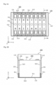
- accommodating portions 130 for accommodating the energy storage devices 300 are formed in the outer case body 100.
- the accommodating portion 130 is a rectangular parallelepiped space surrounded by two partition portions 120 and the bottom wall portion 111 and two side wall portions 112 of the casing 110, and the energy storage device 300 is accommodated in each accommodating portion 130. That is, the accommodating portions 130 are portions for accommodating the energy storage devices 300 which are formed by partitioning an internal space of the casing 110 by the partition portions 120.
- the energy storage device 300 is accommodated in each accommodating portion 130 formed in the outer case body 100 in such a manner that the energy storage device 300 is inserted between two partition portions 120 through the opening formed on an upper portion of the casing 110.
- the outer case body 100 includes the partition portions 120 which partition the inside of the outer case body 100 into the accommodating portions 130 for accommodating the energy storage devices 300.
- eight accommodating portions 130 are disposed for eight energy storage devices 300.
- the energy storage devices 300 are disposed in the accommodating portions 130 formed in the outer case body 100 without being exposed from the wall surfaces of the outer case body 100.
- An adhesive material 510 is disposed between the bottom surface portion 311 of the energy storage device 300 and the bottom wall portion 111 of the outer case body 100. That is, the adhesive material 510 is an adhesive agent which is injected (filled) between an outer surface (first surface) of the bottom surface portion 311 of the energy storage device 300 and an inner surface of the bottom wall portion 111 of the outer case body 100 and makes the outer surface (the first surface) of the bottom surface portion 311 and the inner surface of the bottom wall portion 111 adhere to each other by surface adhesion.
- the surface adhesion means a state where the outer surface and the inner surface are adhered to each other over a face-shaped region, and is a concept which excludes a state where the surfaces are adhered to each other over a line-shaped region and a state where the surfaces are adhered to each other in a point-shaped region.
- the adhesive material 510 is disposed over the entire outer surface of the bottom surface portion 311 of the energy storage device 300 and makes the outer surface of the bottom surface portion 311 and the inner surface of the bottom wall portion 111 of the outer case body 100 adhere to each other by surface adhesion.
- the adhesive agent it is possible to use an adhesive agent which is in a liquid form before being injected (filled) and is solidified after being injected (filled) so as to make the surfaces adhere to each other by surface adhesion, an adhesive agent which is in the form of gel before injected, a solid-form adhesive agent such as a hot-melt adhesive agent or the like.
- An adhesive material 511 is disposed in the gap 131 formed between the short side surface portion 313 of the energy storage device 300 and the side wall portion 112 of the outer case body 100. That is, the adhesive material 511 is an adhesive agent which is injected into the gap 131 formed between the outer surface (the second surface) of the short side surface portion 313 of the energy storage device 300 and the inner surface of the side wall portion 112 of the outer case body 100 and makes the outer surface (the second surface) of the short side surface portion 313 and the inner surface of the side wall portion 112 adhere to each other by surface adhesion.
- the adhesive material 511 is injected into the gap 131 such that an injecting height of the adhesive material 511 becomes approximately one fifth to one fourth of a height of the short side surface portion 313 of the energy storage device 300.
- the injecting height of the adhesive material 511 is not particularly limited.
- the energy storage apparatus 10 includes an adhesive material which is injected between at least one surface out of the first surface (the outer surface of the bottom surface portion 311) and the second surface (the outer surface of the short side surface portion 313) which are two surfaces of the energy storage device 300 disposed adjacently to each other and the inner surface of the outer case 11 and makes the above-mentioned at least one surface and the inner surface of the outer case 11 adhere to each other by surface adhesion.
- the energy storage apparatus 10 includes the adhesive materials 510, 511 which are injected between two surfaces, that is, the first surface (the outer surface of the bottom surface portion 311) and the second surface (the outer surface of the short side surface portion 313) and the inner surfaces of the outer case body 100 respectively and make these two surfaces adhere to the inner surfaces of the outer case body 100 by surface adhesion.
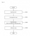
- Fig. 6 is a flowchart showing steps of adhering the energy storage device 300 to the outer case 11 in the method of manufacturing the energy storage apparatus 10.
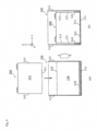
- Fig. 7 is a view for describing the steps of adhering the energy storage device 300 to the outer case 11 in the method of manufacturing the energy storage apparatus 10 .
- an adhesive agent is injected into the outer case 11 (S102). That is, before an arrangement step described later is performed, the adhesive agent is injected onto a surface of the outer case 11 in the outer case 11 which oppositely faces the first surface of the energy storage device 300.
- the adhesive material 510 is injected onto the surface of the outer case 11 in the outer case 11 (the inner surface of the bottom wall portion 111 of the outer case body 100) which oppositely faces the first surface (the outer surface of the bottom surface portion 311) of the energy storage device 300.
- the energy storage device 300 is disposed in the outer case 11 (S104). That is, the energy storage device 300 is disposed in the outer case 11 such that the adhesive material is disposed between the first surface of the energy storage device 300 and the inner surface of the outer case 11. To be more specific, as shown in (b) of Fig. 7 , the energy storage device 300 is disposed in the outer case body 100 such that the adhesive material 510 is disposed between the outer surface of the bottom surface portion 311 and the inner surface of the bottom wall portion 111.
- the energy storage device 300 is disposed in the accommodating portion 130 for the energy storage device 300 which is formed by partitioning the inside of the outer case 11 by the partition portions 120 without exposing the energy storage device 300 from the wall surfaces of the outer case 11.
- the adhesive material 511 is injected in the gaps 131 between the second surfaces (the outer surfaces of the short side surface portions 313) of the energy storage device 300 and the inner surfaces (the inner surfaces of the side wall portions 112 of the outer case body 100) of the outer case 11.
- an adhering step by performing the arrangement step and the injecting steps (the ante-arrangement injecting step and the post-arrangement injecting step), at least one surface out of the first surface and the second surface which are two surfaces of the energy storage device 300 disposed adjacently to each other is adhered to the inner surface of the outer case 11 by surface adhesion (S108).
- the first surface and the second surface of the energy storage device 300 are adhered to the inner surfaces of the outer case 11 by surface adhesion.
- the second surface of the energy storage device 300 can be easily adhered to the inner surface of the outer case 11.
- the energy storage apparatus 10 includes an adhesive material which is injected between at least one surface out of two surfaces of the energy storage device 300 disposed adjacently to each other and the inner surface of the outer case 11.
- the energy storage apparatus 10 includes the adhesive materials 510, 511 which are injected between the first surface and the second surface which are two surfaces of the energy storage device 300 disposed adjacently to each other and the inner surfaces of the outer case 11 respectively. Accordingly, as described above, in the energy storage apparatus 10, the energy storage device 300 can be easily adhered to the outer case 11.
- the energy storage apparatus 10 is configured such that the energy storage device 300 is not exposed from the wall surfaces of the outer case 11. Accordingly, the energy storage device 300 can be easily adhered to the outer case 11 while suppressing protrusion of an injected adhesive material to the outside of the outer case 11.
- the movement of the energy storage device 300 in the outer case 11 is restricted. Accordingly, it is possible to suppress the occurrence of a phenomenon that the energy storage device 300 is moved so that a load is applied to the bus bar 400. It is also possible to suppress the occurrence of a phenomenon that the energy storage device 300 impinges on other members in the outer case 11 thus generating sound, and such an advantageous effect leads to the improvement of the quality. Further, it is unnecessary to provide a binding member for binding the energy storage devices 300 and hence, the number of parts can be reduced thus realizing the reduction of cost.
- Fig. 8 is a flowchart showing steps of adhering an energy storage device 300 to an outer case 11 in a method of manufacturing an energy storage apparatus 10 according to the modification 1.
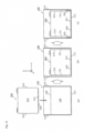
- Fig. 9 is a view for describing the steps of adhering the energy storage device 300 to the outer case 11 in the method of manufacturing the energy storage apparatus 10 according to the modification 1 .
- an adhesive material is injected into the outer case 11 (S202). That is, before an arrangement step described later is performed, an adhesive material is, in the outer case 11, injected onto a surface of the outer case 11 which oppositely faces a first surface of the energy storage device 300.
- an adhesive material 520 is injected onto a surface of the outer case 11 (an inner surface of a bottom wall portion 111 of the outer case body 100) which oppositely faces a first surface (an outer surface of a bottom surface portion 311) of the energy storage device 300.
- a larger amount of adhesive material 520 (for example, a sum of an amount of the adhesive material 510 and an amount of the adhesive material 511) than an amount of the adhesive material 510 which is injected in the ante-arrangement injecting step (S102 in Fig. 6 ) in the above-mentioned aspect is injected.
- the energy storage device 300 is disposed in the outer case body 100 such that an adhesive material 521 is disposed between the first surface (the outer surface of the bottom surface portion 311) of the energy storage device 300 and the inner surface of the bottom wall portion 111, and an adhesive material 522 is disposed in gaps 131 formed between the second surfaces (outer surfaces of short side surface portions 313) of the energy storage device 300 and inner surfaces of side wall portions 112.
- the energy storage device 300 can be disposed in an accommodating portion 130 for the energy storage device 300 which is formed by partitioning the inside of the outer case 11 by partition portions 120 without being exposed from the wall surfaces of the outer case 11.
- the first surface and the second surface which are two surfaces of the energy storage device 300 disposed adjacently to each other are adhered to the inner surfaces of the outer case 11 by surface adhesion (S208). That is, since the adhesive materials 521, 522 are solidified due to drying or the like after the arrangement step and the injecting step, the outer surface of the bottom surface portion 311 and the outer surfaces of the short side surface portions 313 of the energy storage device 300 are adhered to the inner surface of the bottom wall portion 111 and the inner surfaces of the side wall portions 112 of the outer case body 100 respectively by surface adhesion.
- the first surface and the second surfaces which are two surfaces of the energy storage device 300 disposed adjacently to each other are adhered to the inner surfaces of the outer case 11 respectively by surface adhesion (S308). That is, since the adhesive materials 530, 531 are solidified by drying or the like after the arrangement step and the injecting step, the outer surface of the bottom surface portion 311 and the outer surfaces of the short side surface portions 313 of the energy storage device 300 are adhered to the inner surface of the bottom wall portion 111 and the inner surfaces of the side wall portions 112 of the outer case body 100 respectively by surface adhesion.
- the method of manufacturing the energy storage apparatus 10 according to the modification 2 can acquire substantially the same advantageous effects as the above-mentioned aspect.
- this modification by applying an adhesive material to the first surface of the energy storage device 300 before the energy storage device 300 is disposed in the outer case 11, the first surface of the energy storage device 300 can be fixed to the outer case 11.
- the ante-arrangement injecting step (S102 in Fig. 6 ) is performed before the arrangement step (S104 in Fig. 6 ).
- the ante-arrangement injecting step is not performed.
- the energy storage device 300 is placed on the bottom wall portion 111a of the outer case body 101, and the inner surface of the bottom wall portion 111a and the outer surface of the bottom surface portion 311 are brought into contact with each other.
- the recessed portions are formed at positions of the bottom wall portions 111b of the outer case body 101 and hence, the spaces 140 and the gaps 131 are formed between the outer surface of the bottom surface portion 311 and the outer surfaces of the short side surface portion 313 of the energy storage device 300 and the inner surface of the bottom wall portion 111b and the inner surfaces of the side wall portions 112 of the outer case body 101 respectively.
- an adhesive material can be disposed in the spaces 140 and the gaps 131.
- an adhesive material is injected into the outer case 11 (S406). That is, an adhesive material is injected between the first surface and the second surfaces of the energy storage device 300 and the inner surfaces of the outer case 11.
- an adhesive material 540 is injected into the spaces 140 and the gaps 131 formed between the first surface (the outer surface of the bottom surface portion 311) and the second surfaces (the outer surfaces of the short side surface portions 313) of the energy storage device 300 and the inner surface (the inner surface of the bottom wall portion 111b and the inner surfaces of the side wall portions 112 of the outer case body 101) of the outer case 11 respectively.
- the first surface and the second surface which are two surfaces of the energy storage device 300 disposed adjacently to each other are adhered to the inner surfaces of the outer case 11 respectively (S408). That is, since the adhesive material 540 is solidified by drying or the like after the arrangement step and the injecting step, the outer surface of the bottom surface portion 311 and the outer surfaces of the short side surface portions 313 of the energy storage device 300 are adhered to the inner surfaces of the bottom wall portions 111b and the inner surfaces of the side wall portions 112 of the outer case body 101 respectively by surface adhesion. In this manner, the adhesive material 540 is injected into the recessed portions of the outer case body 101 thus making the first surface and the second surface of the energy storage device 300 and the inner surfaces of the outer case 11 adhere to each other.
- the energy storage apparatus 10 is configured such that two surfaces of the energy storage device 300 disposed adjacently to each other are adhered to the outer case 11 by the adhesive agent injected into the recessed portions of the outer case 11. Accordingly, the energy storage device 300 can be easily and firmly adhered to the outer case 11.
- the projecting portions 114 are projecting portions which are formed on portions of an inner surface of the outer case 11 which are adhered to the energy storage device 300 by surface adhesion using the adhesive material 510, and extend along the inner surface of the outer case 11.
- projecting portions 114a to 114d having a triangular cross-sectional shape are formed in an extending manner along the inner surface of the bottom wall portion 111c.
- the projecting portions 114a, 114b are the projecting portions arranged on a positive electrode side of the energy storage device 300, and the projecting portions 114c, 114d are the projecting portions arranged on a negative electrode side of the energy storage device 300.
- a projection height of the projecting portions 114 is approximately less than 1 mm, for example.
- a space is formed between distal end portions of the projecting portions 114a, 114b on the plus side in the Y axis direction, and this space forms the flow passage 115 on a positive electrode side.
- a distance between the projecting portions 114c, 114d is narrowed as the projecting portions 114c, 114d extend toward a minus side in the Y axis direction, a space is formed between distal end portions of the projecting portions 114c, 114d on the minus side in the Y axis direction, and this space forms the flow passage 115 on a negative electrode side.
- the flow passages 115 are also arranged just below the positive electrode terminal 320 and the negative electrode terminal 330. In this manner, the plurality of projecting portions 114 are formed on the inner surface of the outer case 11 with respect to the respective energy storage devices 300.
- the flow passage 115 for the adhesive material 510 is formed on the side of the projecting portion 114. Accordingly, after injecting of the adhesive material 510, when an amount of adhesive material 510 is large, it is possible to make the adhesive material 510 flow out through the flow passage 115. Further, when an amount of adhesive material 510 is small, it is possible to make the adhesive material 510 flow in through the flow passage 115. Accordingly, an amount of the adhesive material 510 can be adjusted by the flow passage 115 and hence, the energy storage device 300 can be easily and firmly adhered to the outer case 11.
- At least a portion of the projecting portion 114 is arranged just below the region ranging from the electrode terminal to the end portion of the energy storage device 300. Accordingly, in fixing the energy storage device 300 by pressing the electrode terminal or the end portion of the energy storage device 300, the energy storage device 300 can be stably fixed to the outer case 11.
- the cross section of the projecting portion 114 is not limited to a triangular shape, and may be a polygonal shape (a quadrangular shape or the like) besides a triangular shape, a curved shape such as a semicircular shape, a semi-oblong shape or a semielliptical shape.
- a cross section having a shape where a width is narrowed toward an upper end makes an adhesive material difficult to remain on a distal end of the projecting portion 114 and hence, such a shape is preferable.
- a cross section of the projecting portion 114 has a shape formed of a curve, a force which the projecting portion 114 receives from above can be dispersed.
- the projecting portions 114 may be formed along the bottom surface portion 311 of the energy storage device 300.
- the energy storage device 300 can be firmly fixed to the outer case 11. For example, when the bottom surface portion 311 is warped upward, a height of the projecting portion 114 is set higher as the projecting 114 extends toward a center portion.
- the projecting portions 114 may be formed in a shape where the projecting portion 114 extends in the Y axis direction. Alternatively, the projecting portions 114 may be formed in a shape where the projecting portions 114 extend in a plurality of directions among the X axis direction, the Y axis direction and oblique directions and intersect with each other (for example, a meshed shape).
- the projecting portions 114 may not be formed by working, and the projecting portion 114 may be formed by making use of a shape where roughness after working remains.
- the flow passage 115 may not be arranged between two projecting portions 114, and a space arranged on a side of the projecting portion 114 may be used as the flow passage 115. Further, the flow passage 115 may be a space formed by indenting an upper surface of one projecting portion 114, and a cross-sectional shape of such an indented portion may be any shape such as a rectangular shape, a V shape or a U shape.
- the flow passage 115 may be a through hole formed in the projecting portion 114, and a cross-sectional shape of the through hole may be any shape such as a polygonal shape, a circular shape or a semicircular shape. That is, it is sufficient that the flow passage 115 be a flow passage (space) which traverses the projecting portion 114, and the shape of the flow passage 115 is not limited.
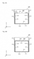
- Fig. 16A and Fig. 16B are cross-sectional views showing the configuration where the energy storage device 300 according to the modification 5 is accommodated in an outer case body 100.
- Fig. 16A and Fig. 16B are views which correspond to Fig. 5B .
- an adhesive material 512 is injected up to upper end portions of the short side surface portions 313 of the energy storage device 300. That is, an adhesive material 510 is injected between a first surface (an outer surface of a bottom surface portion 311) of the energy storage device 300 and an inner surface (an inner surface of a bottom wall portion 111 of the outer case body 100) of the outer case 11, and an adhesive material 512 is injected between second surfaces (outer surfaces of the short side surface portions 313) of the energy storage device 300 and inner surfaces (inner surfaces of side wall portions 112 of the outer case body 100) of the outer case 11.
- an injecting height of the adhesive material 512 is not particularly limited, in this modification, the injecting height of the adhesive material 512 is set equal to or more than an injecting height in the above-mentioned aspect (for example, one fourth or more of a height of the short side surface portions 313 of the energy storage device 300). In this manner, the adhesive material 512 is injected between a bottom surface of the energy storage device 300 which forms the first surface and the inner surface of the outer case 11 and is also injected between surfaces of side surfaces of the energy storage device 300 which form the second surfaces ranging from lower ends of the side surfaces to a predetermined height from the lower ends and the inner surfaces of the outer case 11.
- the energy storage apparatus 10 includes a bus bar frame 600 for positioning bus bars 400 with respect to the energy storage devices 300 above the energy storage devices 300, and the adhesive material 513 may be injected up to a height of the bus bar frame 600.
- the energy storage apparatus 10 can acquire substantially the same advantageous effects as the above-mentioned aspect.
- the energy storage apparatus 10 is configured such that the energy storage apparatus 10 includes an adhesive material injected up to a predetermined height of the side surfaces of the energy storage device 300 and hence, the energy storage device 300 can be easily and firmly adhered to the outer case 11.
- the bus bar frame 600 also has a function of fixing the energy storage device 300 to the outer case body 100 by pressing the energy storage device 300 from above and hence, the bus bar frame 600 can further firmly fix the energy storage device 300 to the outer case body 100 by the adhesive material 513.
- Fig. 17 is a plan view showing a configuration where an energy storage device 300 according to the modification 6 is accommodated in an outer case body 103. To be more specific, Fig. 17 is a view corresponding to Fig. 5A .
- an outer case body 103 has partition portions 121 in place of the partition portions 120 of the outer case body 100 of the above-mentioned aspect.
- the partition portions 121 are rectangular-shaped flat-plate-like ribs which project from the side wall portions 112. That is, the partition portion 121 is configured such that a center portion of the partition portion 120 in the above-mentioned aspect is cut away.
- An adhesive material 511 is injected into gaps 131 each of which is formed between the partition portions 121.
- a shape of the partition portion 121 is not limited to the shape in the above-mentioned aspect.
- the energy storage apparatus 10 according to the modification 6 can acquire substantially the same advantageous effects as the above-mentioned aspect.
- the partition portion 121 can be formed small in size and hence, an amount of a material used for forming the outer case body 103 can be reduced.
- partition portions 120 of the above-mentioned embodiment are formed by connecting two energy storage devices 300 in parallel, and four sets of energy storage device groups are connected to each other in series.
- the partition portion 120 of the above-mentioned aspect be disposed between the energy storage devices 300 connected to each other in series. Accordingly, the partition portion 120 of the above-mentioned aspect may be disposed between the energy storage device groups, and the partition portion 121 of this modification may be disposed between the energy storage devices 300 in each energy storage device group.
- the energy storage apparatus 10 includes the plurality of energy storage devices 300.
- the energy storage apparatus 10 may include only one energy storage device 300.
- the adhesive material is an adhesive agent.
- the adhesive material is not limited to the adhesive agent, and may be a double-applied adhesive tape, or an adhesive material having the surface fastener structure which allows the adhesion in a detachable manner and is referred to as Magic Tape (registered trademark) or Velcro (registered trademark) tape.
- an adhesive material is disposed on both short side surface sides of all energy storage devices 300.
- an adhesive material may not be disposed on either one of both short side surface sides.
- the outer case body 101 may be configured such that the outer case body 101 has only one bottom wall portion 111b on one side wall portion 112 side (only one recessed portion is formed).
- the entire outer surface of the bottom surface portion 311 of the energy storage device 300 is adhered to the inner surface of the bottom wall portion 111 of the outer case body by surface adhesion.
- a region where the surface adhesion is applied is not limited to the entire outer surface of the bottom surface portion 311 and may be a partial region of the outer surface of the bottom surface portion 311.
- the energy storage device 300 is disposed such that the container lid portion 314 is directed upward. That is, the outer surface of the bottom surface portion 311 of the energy storage device 300 forms the first surface, and the outer surfaces of the short side surface portions 313 of the energy storage device 300 form the second surfaces.
- the energy storage device 300 may be disposed such that the container lid portion 314 is directed sideward. That is, for example, the outer surface of the short side surface portion 313 of the energy storage device 300 forms the first surface, and the outer surface of the bottom surface portion 311 and the outer surface of the container lid portion 314 form the second surfaces.
- the energy storage device 300 may be disposed such that the container lid portion 314 is directed downward, and the outer surface of the container lid portion 314 may form the first surface. Still further, the outer surface of the long side surface portion 312 may form the first surface or the second surface.
Landscapes
- Engineering & Computer Science (AREA)
- Chemical & Material Sciences (AREA)
- Power Engineering (AREA)
- Chemical Kinetics & Catalysis (AREA)
- Electrochemistry (AREA)
- General Chemical & Material Sciences (AREA)
- Microelectronics & Electronic Packaging (AREA)
- Manufacturing & Machinery (AREA)
- Materials Engineering (AREA)
- Battery Mounting, Suspending (AREA)
- Sealing Battery Cases Or Jackets (AREA)
- Electric Double-Layer Capacitors Or The Like (AREA)
Claims (13)
- Energiespeicherungsvorrichtung (10), die umfasst:eine Energiespeichereinrichtung (300);ein äußeres Gehäuse (100), das von einem rechteckig geformten Bodenwandabschnitt (111, 111c) sowie rechteckig geformten Seitenwandabschnitten (112, 113) gebildet wird, die vier Seiten des Bodenwandabschnittss (111, 111c) umgeben; sowieein Klebstoffmaterial (510), das zwischen eine erste Fläche (311) der Energiespeichereinrichtung (300) und eine Innenfläche des Bodenwandabschnittss (111, 111c) des äußeren Gehäuses (100) eingespritzt ist, so dass die erste Fläche und eine Innenfläche des äußeren Gehäuses durch Oberflächenhaftung aneinander haften,dadurch gekennzeichnet, dassein vorstehender Abschnitt (111a, 114), der in Richtung der Energiespeichereinrichtung (300) vorsteht, an dem Bodenwandabschnitt (111, 111c) vorsteht, der durch Oberflächenhaftung aufgrund des Klebstoffmaterials an der Energiespeichereinrichtung (300) haftet;die Energiespeichereinrichtung (300) an dem Bodenwandabschnitt (111, 111c) und den Seitenwandabschnitten (112, 113) nicht freiliegt;der vorstehende Abschnitt (111a, 114) und die Energiespeichereinrichtung (300) in Kontakt miteinander gebracht werden;ein Zwischenraum (131) zwischen einer zweiten Fläche (313) der Energiespeichereinrichtung (300), die eine Fläche der Energiespeichereinrichtung (300) ist, die an die erste Fläche (311) angrenzend angeordnet ist, und einem der Seitenwandabschnitte (112) des äußeren Gehäuses (100) ausgebildet ist; unddas Klebstoffmaterial (510) in den Zwischenraum (131) zwischen der zweiten Fläche (313) der Energiespeichereinrichtung (300) und einer Innenfläche des einen der Seitenwandabschnitte (112) des äußeren Gehäuses (100) eingespritzt ist, so dass die zweite Fläche und die Innenfläche des äußeren Gehäuses durch Oberflächenhaftung aneinander haften.
- Energiespeicherungsvorrichtung (10) nach Anspruch 1, wobei ein Strömungsdurchlass (115) für das Klebstoffmaterial (510), der den vorstehenden Abschnitt durchläuft, an der Innenfläche des äußeren Gehäuses (100) und an einer Seite des vorstehenden Abschnitts (114) ausgebildet ist.
- Energiespeicherungsvorrichtung (10) nach Anspruch 2, wobei wenigstens zwei vorstehende Abschnitte (114a, 114b) an dem Bodenwandabschnitt (111c) ausgebildet sind und sich die wenigstens zwei vorstehenden Abschnitte (114a, 114b) an dem Bodenwandabschnitt (111c) entlang erstrecken,ein Raum zwischen zwei der wenigstens zwei vorstehenden Abschnitte (114a, 114b) Teil des Strömungsdurchlasses (115) ist, undein Abstand zwischen den zwei vorstehenden Abschnitten (114a, 114b) mit Annäherung der zwei der wenigstens zwei vorstehenden Abschnitte (114a, 114b) an den Strömungsdurchlass (115) schmaler wird.
- Energiespeicherungsvorrichtung (1) nach einem der Ansprüche 1 bis 3, wobei die Energiespeicherungsvorrichtung (1) eine Vielzahl von Energiespeichereinrichtungen (300) enthält, und
eine Vielzahl vorstehender Abschnitte (111a, 114) in Entsprechung zu den jeweiligen Energiespeichereinrichtungen (300) an dem Bodenwandabschnitt (111, 111c) ausgebildet sind. - Energiespeicherungsvorrichtung (10) nach einem der Ansprüche 1 bis 4, wobei die Energiespeichereinrichtung (300) einen Elektrodenanschluss (320, 330) enthält,
wenigstens ein Teil des vorstehenden Abschnitts (114) sich mit einem Bereich, der von dem Elektrodenabschnitt (320, 330) bis zu einem Endabschnitt der Energiespeichereinrichtung (300) reicht, in einer Richtung gesehen, in der der vorstehende Abschnitt (41) vorsteht, überlappt. - Energiespeicherungsvorrichtung (10) nach einem der Ansprüche 1 bis 5, wobei das äußere Gehäuse (100) einen Trennabschnitt (120) enthält, der einen Innenraum des äußeren Gehäuses (100) unterteilt und so einen Aufnahmeabschnitt für die Energiespeichereinrichtung (300) bildet.
- Energiespeicherungsvorrichtung (10) nach einem der Ansprüche 1 bis 6, wobei das äußere Gehäuse (100) einen vertieften Abschnitt (140) enthält, der einen Zwischenraum zwischen einer Innenfläche des äußeren Gehäuses (100) und der ersten Fläche sowie der zweiten Fläche der Energiespeichereinrichtung (300) bildet, und
das Klebstoffmaterial (510) in den vertieften Abschnitt (140) eingespritzt ist und die erste Fläche sowie die zweite Fläche der Energiespeichereinrichtung (300) und die Innenfläche des äußeren Gehäuses (100) durch Oberflächenhaftung aneinander haften lässt. - Energiespeicherungsvorrichtung (10) nach einem der Ansprüche 1 bis 7, wobei die erste Fläche eine Bodenfläche der Energiespeichereinrichtung (300) ist und die zweite Fläche eine Seitenfläche der Energiespeichereinrichtung (300) ist,
das Klebstoffmaterial (510) zwischen die erste Fläche und die Innenfläche des äußeren Gehäuses (100) sowie zwischen die zweite Fläche, die von einem unteren Ende der Seitenfläche bis zu einer vorgegebenen Höhe von dem unteren Ende aus reicht, und die Innenfläche des äußeren Gehäuses (300) eingespritzt ist. - Energiespeicherungsvorrichtung (10) nach Anspruch 1, wobei der Bodenwandabschnitt (111c) eine Vielzahl vorstehender Abschnitte (114), die in Richtung einer einzelnen Fläche der Energiespeichereinrichtung (300) vorstehen, sowie einen Strömungskanal aufweist, der die Vielzahl vorstehender Abschnitte durchläuft.
- Energiespeicherungsvorrichtung (10) nach Anspruch 9, wobei das Klebstoffmaterial (510) zwischen der Vielzahl vorstehender Abschnitte (114) angeordnet ist.
- Energiespeicherungsvorrichtung (10) nach Anspruch 9, wobei die Energiespeichereinrichtung (300) kurze Seitenflächenabschnitte (313) hat und das Klebstoffmaterial (510) zwischen der Vielzahl vorstehender Abschnitte (114) angeordnet ist und das Klebstoffmaterial (510) zwischen einer Innenfläche der Seitenwandabschnitte (112) und einer Außenfläche der kurzen Seitenflächenabschnitte (313) angeordnet ist.
- Verfahren zum Herstellen einer Energiespeicherungsvorrichtung (10), die eine Energiespeichereinrichtung (300) sowie ein äußeres Gehäuse (100) enthält, das von einem rechteckig geformten Bodenwandabschnitt (111, 111c) und rechteckig geformten Seitenwandabschnitten (112, 113) gebildet wird, die vier Seiten des Bodenwandabschnittss umgeben, wobei ein vorstehender Abschnitt (114), der in Richtung der Energiespeichereinrichtung (300) vorsteht, an dem Bodenwandabschnitt (111, 111c) ausgebildet ist, der durch Oberflächenhaftung aufgrund des Klebstoffmaterials an der Energiespeichereinrichtung (300) haftet, wobei das Verfahren umfasst:einen Anordnungs-Schritt (S104), in dem die Energiespeichereinrichtung (300) so in dem äußeren Gehäuse (100) angeordnet wird, dass die Energiespeichereinrichtung (300) an dem Bodenwandabschnitt (111, 111c) und den Seitenwandabschnitten (112, 113) nicht freiliegt, wobei der vorstehende Abschnitt (111a, 114) und die Energiespeichereinrichtung (300) in Kontakt miteinander gebracht werden;einen Einspritz-Schritt (S106), in dem ein Klebstoffmaterial (510) in das äußere Gehäuse (100) eingespritzt wird; sowieeinen Anhaft-Schritt (S108), in dem eine erste Fläche (311) der Energiespeichereinrichtung (300) an einer Innenfläche des Bodenwandabschnitts (111, 111c) des äußeren Gehäuses (100) mittels Oberflächenhaftung angehaftet wird, indem der Anordnungs-Schritt und der Einspritz-Schritt durchgeführt werden,wobei ein Zwischenraum (131) zwischen einer zweiten Fläche (313) der Energiespeichereinrichtung (300), die eine Fläche der Energiespeichereinrichtung (300) ist, die an die erste Fläche (311) angrenzend angeordnet ist, und einem der Seitenwandabschnitte (112) des äußeren Gehäuses (100) ausgebildet ist; undin dem Anhaft-Schritt (S108) das Klebstoffmaterial (510) in den Zwischenraum (131) zwischen der zweiten Fläche (313) der Energiespeichereinrichtung (300) und einer Innenfläche des einen der Seitenwandabschnitte (112) des äußeren Gehäuses (100) eingespritzt wird, so dass die zweite Fläche und die Innenfläche des einen der Seitenwandabschnitte (112) des äußeren Gehäuses durch Oberflächenhaftung aneinander haften.
- Verfahren zum Herstellen einer Energiespeicherungsvorrichtung (10), nach Anspruch 12, wobei der Einspritz-Schritt (S106) einen Schritt (S102) zum Einspritzen vor Anordnung, in dem ein Klebstoffmaterial (510) an einer Fläche des äußeren Gehäuses (100) eingespritzt wird, die der ersten Fläche (311) der Energiespeichereinrichtung (300) in dem äußeren Gehäuse (100) gegenüberliegt, vor dem Anordnungs-Schritt (S104) einschließt,in dem Anordnungs-Schritt (S104) die Energiespeichereinrichtung (300) so in dem äußeren Gehäuse (100) angeordnet ist, dass ein Klebstoffmaterial (510) zwischen der ersten Fläche (311) sowie der zweiten Fläche (312, 313) der Energiespeichereinrichtung (300) und einer Innenfläche des äußeren Gehäuses (100) angeordnet ist, undin dem Anhaft-Schritt (S108) die erste Fläche und die zweite Fläche der Energiespeichereinrichtung (300) mittels Oberflächenhaftung an der Innenfläche des äußeren Gehäuses (100) angehaftet werden.
Applications Claiming Priority (2)
| Application Number | Priority Date | Filing Date | Title |
|---|---|---|---|
| JP2015192336 | 2015-09-29 | ||
| PCT/JP2016/073442 WO2017056742A1 (ja) | 2015-09-29 | 2016-08-09 | 蓄電装置及び蓄電装置の製造方法 |
Publications (3)
| Publication Number | Publication Date |
|---|---|
| EP3358640A1 EP3358640A1 (de) | 2018-08-08 |
| EP3358640A4 EP3358640A4 (de) | 2018-08-08 |
| EP3358640B1 true EP3358640B1 (de) | 2025-04-09 |
Family
ID=58423465
Family Applications (1)
| Application Number | Title | Priority Date | Filing Date |
|---|---|---|---|
| EP16850919.8A Active EP3358640B1 (de) | 2015-09-29 | 2016-08-09 | Elektrizitätsspeichervorrichtung und verfahren zur herstellung einer elektrizitätsspeichervorrichtung |
Country Status (5)
| Country | Link |
|---|---|
| US (1) | US11114718B2 (de) |
| EP (1) | EP3358640B1 (de) |
| JP (1) | JP6863286B2 (de) |
| CN (1) | CN108140766B (de) |
| WO (1) | WO2017056742A1 (de) |
Families Citing this family (13)
| Publication number | Priority date | Publication date | Assignee | Title |
|---|---|---|---|---|
| CN105762316A (zh) * | 2016-05-20 | 2016-07-13 | 宁德时代新能源科技股份有限公司 | 一种电池箱 |
| CN208014778U (zh) * | 2018-03-30 | 2018-10-26 | 宁德时代新能源科技股份有限公司 | 电池箱体以及电池箱 |
| DE102018115717A1 (de) * | 2018-06-28 | 2020-01-02 | Lisa Dräxlmaier GmbH | Energiespeichereinrichtung und herstellverfahren |
| DE102018131340B3 (de) | 2018-12-07 | 2020-06-10 | Benteler Automobiltechnik Gmbh | Stromschienenanordnung und Kraftfahrzeug |
| CN113841467A (zh) * | 2019-05-23 | 2021-12-24 | 3M创新有限公司 | 用于电子设备中的部件的紧固件 |
| CN117799413A (zh) * | 2019-11-29 | 2024-04-02 | 比亚迪股份有限公司 | 电池包和电动车 |
| JP7244405B2 (ja) * | 2019-12-06 | 2023-03-22 | トヨタ自動車株式会社 | 電池パックとその分解方法 |
| US20230017845A1 (en) * | 2019-12-27 | 2023-01-19 | Panasonic Intellectual Property Management Co., Ltd. | Power storage module |
| KR102890553B1 (ko) * | 2020-06-29 | 2025-11-26 | 주식회사 엘지에너지솔루션 | 연쇄발화를 방지하는 전지 모듈 제조방법 |
| USD910546S1 (en) * | 2020-07-10 | 2021-02-16 | Inventus Power, Inc. | Battery |
| USD911933S1 (en) * | 2020-07-10 | 2021-03-02 | Inventus Power, Inc. | Battery |
| DE102021002803A1 (de) * | 2021-05-31 | 2021-07-15 | Daimler Ag | Batterieanordnung für ein Kraftfahrzeug |
| KR20230021502A (ko) * | 2021-08-05 | 2023-02-14 | 삼성에스디아이 주식회사 | 배터리 팩 |
Family Cites Families (26)
| Publication number | Priority date | Publication date | Assignee | Title |
|---|---|---|---|---|
| US3215304A (en) | 1963-06-21 | 1965-11-02 | Walter Glass | Battery case |
| GB1204789A (en) | 1967-03-02 | 1970-09-09 | Matsushita Electric Industrial Co Ltd | Storage battery |
| JPH11126590A (ja) * | 1997-10-22 | 1999-05-11 | Toshiba Battery Co Ltd | 電池パック |
| US7103826B2 (en) * | 2003-07-31 | 2006-09-05 | Hewlett-Packard Development Company, L.P. | Memory system and controller for same |
| KR100560158B1 (ko) * | 2003-09-29 | 2006-03-16 | 주식회사 코캄 | 고 안전성 리튬 이차 전지 및 그 제조방법 |
| US20050238955A1 (en) | 2004-04-26 | 2005-10-27 | Hooke John W | Battery and battery terminal structure and method of manufacture |
| KR100561310B1 (ko) * | 2004-05-31 | 2006-03-15 | 삼성에스디아이 주식회사 | 리튬 폴리머 전지팩 및 코어팩과 케이스의 분리 방법 |
| JP4747539B2 (ja) | 2004-09-13 | 2011-08-17 | マックス株式会社 | 電池パック |
| JP5011678B2 (ja) | 2005-08-12 | 2012-08-29 | ソニー株式会社 | 二次電池 |
| JP4722015B2 (ja) * | 2005-12-29 | 2011-07-13 | 三星エスディアイ株式会社 | ポリマー電池パック |
| FR2924857B1 (fr) * | 2007-12-06 | 2014-06-06 | Valeo Equip Electr Moteur | Dispositif d'alimentation electrique comportant un bac de reception d'unites de stockage a ultra capacite |
| JP2009277433A (ja) | 2008-05-13 | 2009-11-26 | Toshiba Corp | バッテリパック |
| JP2010097723A (ja) | 2008-10-14 | 2010-04-30 | Toshiba Corp | 電池パック |
| KR101084801B1 (ko) * | 2009-02-18 | 2011-11-21 | 삼성에스디아이 주식회사 | 이차 전지의 제조 방법 및 이에 의해 제조된 이차 전지 |
| JP5542549B2 (ja) | 2009-08-31 | 2014-07-09 | 株式会社東芝 | 二次電池装置 |
| JP5209019B2 (ja) | 2010-10-13 | 2013-06-12 | 日立ビークルエナジー株式会社 | 蓄電モジュールおよび蓄電装置 |
| JP2012119158A (ja) | 2010-11-30 | 2012-06-21 | Sanyo Electric Co Ltd | 組電池とこれを装備する電動車両 |
| US9213070B2 (en) | 2011-05-31 | 2015-12-15 | Kabushiki Kaisha Toshiba | Calculation method, calculation system, and calculation apparatus |
| JP6010326B2 (ja) * | 2011-06-02 | 2016-10-19 | 株式会社東芝 | 二次電池装置、二次電池装置の製造方法 |
| WO2013076770A1 (ja) | 2011-11-24 | 2013-05-30 | トヨタ自動車株式会社 | 蓄電装置、車両 |
| JP2013157112A (ja) * | 2012-01-27 | 2013-08-15 | Toshiba Corp | 組電池 |
| KR101877569B1 (ko) * | 2012-03-05 | 2018-07-11 | 삼성에스디아이 주식회사 | 이차 전지 |
| JP2014060088A (ja) | 2012-09-19 | 2014-04-03 | Toshiba Corp | 二次電池装置および二次電池システム |
| JP6079589B2 (ja) * | 2013-11-28 | 2017-02-15 | 豊田合成株式会社 | 電池パックおよびその製造方法 |
| JP6396033B2 (ja) | 2014-02-25 | 2018-09-26 | 株式会社東芝 | 電池モジュールおよび電池セル |
| JP6822048B2 (ja) * | 2016-10-12 | 2021-01-27 | 株式会社Gsユアサ | 蓄電装置 |
-
2016
- 2016-08-09 WO PCT/JP2016/073442 patent/WO2017056742A1/ja not_active Ceased
- 2016-08-09 US US15/763,543 patent/US11114718B2/en active Active
- 2016-08-09 CN CN201680056811.0A patent/CN108140766B/zh active Active
- 2016-08-09 EP EP16850919.8A patent/EP3358640B1/de active Active
- 2016-08-09 JP JP2017542996A patent/JP6863286B2/ja active Active
Also Published As
| Publication number | Publication date |
|---|---|
| WO2017056742A1 (ja) | 2017-04-06 |
| JP6863286B2 (ja) | 2021-04-21 |
| US11114718B2 (en) | 2021-09-07 |
| CN108140766B (zh) | 2021-03-30 |
| US20180269438A1 (en) | 2018-09-20 |
| CN108140766A (zh) | 2018-06-08 |
| EP3358640A1 (de) | 2018-08-08 |
| EP3358640A4 (de) | 2018-08-08 |
| JPWO2017056742A1 (ja) | 2018-07-12 |
Similar Documents
| Publication | Publication Date | Title |
|---|---|---|
| EP3358640B1 (de) | Elektrizitätsspeichervorrichtung und verfahren zur herstellung einer elektrizitätsspeichervorrichtung | |
| US10468646B2 (en) | Energy storage apparatus and manufacturing method of energy storage apparatus | |
| KR102273642B1 (ko) | 이차 전지 | |
| US10003054B2 (en) | Power source pack | |
| EP3352242B1 (de) | Energiespeichervorrichtung | |
| KR102284572B1 (ko) | 이차 전지 | |
| KR101711978B1 (ko) | 이차 전지 | |
| KR102299244B1 (ko) | 이차 전지 및 그 팩 | |
| CN102738498B (zh) | 二次电池 | |
| JP6743664B2 (ja) | 蓄電装置及び蓄電装置の製造方法 | |
| US20170084885A1 (en) | Energy storage apparatus | |
| US20090269620A1 (en) | Battery pack | |
| KR20170045580A (ko) | 이차 전지 모듈 | |
| KR20160150405A (ko) | 이차 전지 및 이차 전지 모듈 | |
| KR102074322B1 (ko) | 통합형 카트리지 및 이를 포함하는 배터리 팩 | |
| JP6891597B2 (ja) | 蓄電装置 | |
| JP7120233B2 (ja) | 蓄電装置 | |
| WO2020174953A1 (ja) | 蓄電装置 | |
| WO2019244413A1 (ja) | 電池パック | |
| US9806304B2 (en) | Secondary battery | |
| JP2016054108A (ja) | 蓄電装置 | |
| JP2019079599A (ja) | 蓄電装置 | |
| JP2014216151A (ja) | 蓄電装置及び蓄電素子 | |
| KR20160054268A (ko) | 이차전지셀 및 이를 포함하는 배터리 모듈 | |
| US20110129699A1 (en) | Battery pack |
Legal Events
| Date | Code | Title | Description |
|---|---|---|---|
| STAA | Information on the status of an ep patent application or granted ep patent |
Free format text: STATUS: THE INTERNATIONAL PUBLICATION HAS BEEN MADE |
|
| PUAI | Public reference made under article 153(3) epc to a published international application that has entered the european phase |
Free format text: ORIGINAL CODE: 0009012 |
|
| STAA | Information on the status of an ep patent application or granted ep patent |
Free format text: STATUS: REQUEST FOR EXAMINATION WAS MADE |
|
| 17P | Request for examination filed |
Effective date: 20180328 |
|
| A4 | Supplementary search report drawn up and despatched |
Effective date: 20180611 |
|
| AK | Designated contracting states |
Kind code of ref document: A1 Designated state(s): AL AT BE BG CH CY CZ DE DK EE ES FI FR GB GR HR HU IE IS IT LI LT LU LV MC MK MT NL NO PL PT RO RS SE SI SK SM TR |
|
| AX | Request for extension of the european patent |
Extension state: BA ME |
|
| DAV | Request for validation of the european patent (deleted) | ||
| DAX | Request for extension of the european patent (deleted) | ||
| STAA | Information on the status of an ep patent application or granted ep patent |
Free format text: STATUS: EXAMINATION IS IN PROGRESS |
|
| 17Q | First examination report despatched |
Effective date: 20190221 |
|
| REG | Reference to a national code |
Ref country code: DE Ref legal event code: R079 Free format text: PREVIOUS MAIN CLASS: H01M0002100000 Ipc: H01M0050209000 Ref document number: 602016091864 Country of ref document: DE |
|
| GRAP | Despatch of communication of intention to grant a patent |
Free format text: ORIGINAL CODE: EPIDOSNIGR1 |
|
| STAA | Information on the status of an ep patent application or granted ep patent |
Free format text: STATUS: GRANT OF PATENT IS INTENDED |
|
| RIC1 | Information provided on ipc code assigned before grant |
Ipc: H01M 50/227 20210101ALN20241018BHEP Ipc: H01M 50/119 20210101ALN20241018BHEP Ipc: H01M 50/55 20210101ALI20241018BHEP Ipc: H01M 50/291 20210101ALI20241018BHEP Ipc: H01M 50/271 20210101ALI20241018BHEP Ipc: H01G 11/84 20130101ALI20241018BHEP Ipc: H01G 11/82 20130101ALI20241018BHEP Ipc: H01G 11/10 20130101ALI20241018BHEP Ipc: H01M 50/209 20210101AFI20241018BHEP |
|
| INTG | Intention to grant announced |
Effective date: 20241104 |
|
| GRAS | Grant fee paid |
Free format text: ORIGINAL CODE: EPIDOSNIGR3 |
|
| GRAA | (expected) grant |
Free format text: ORIGINAL CODE: 0009210 |
|
| STAA | Information on the status of an ep patent application or granted ep patent |
Free format text: STATUS: THE PATENT HAS BEEN GRANTED |
|
| AK | Designated contracting states |
Kind code of ref document: B1 Designated state(s): AL AT BE BG CH CY CZ DE DK EE ES FI FR GB GR HR HU IE IS IT LI LT LU LV MC MK MT NL NO PL PT RO RS SE SI SK SM TR |
|
| REG | Reference to a national code |
Ref country code: GB Ref legal event code: FG4D |
|
| REG | Reference to a national code |
Ref country code: CH Ref legal event code: EP |
|
| REG | Reference to a national code |
Ref country code: DE Ref legal event code: R096 Ref document number: 602016091864 Country of ref document: DE |
|
| REG | Reference to a national code |
Ref country code: IE Ref legal event code: FG4D |
|
| REG | Reference to a national code |
Ref country code: NL Ref legal event code: MP Effective date: 20250409 |
|
| PG25 | Lapsed in a contracting state [announced via postgrant information from national office to epo] |
Ref country code: NL Free format text: LAPSE BECAUSE OF FAILURE TO SUBMIT A TRANSLATION OF THE DESCRIPTION OR TO PAY THE FEE WITHIN THE PRESCRIBED TIME-LIMIT Effective date: 20250409 |
|
| REG | Reference to a national code |
Ref country code: AT Ref legal event code: MK05 Ref document number: 1784415 Country of ref document: AT Kind code of ref document: T Effective date: 20250409 |
|
| PG25 | Lapsed in a contracting state [announced via postgrant information from national office to epo] |
Ref country code: FI Free format text: LAPSE BECAUSE OF FAILURE TO SUBMIT A TRANSLATION OF THE DESCRIPTION OR TO PAY THE FEE WITHIN THE PRESCRIBED TIME-LIMIT Effective date: 20250409 Ref country code: ES Free format text: LAPSE BECAUSE OF FAILURE TO SUBMIT A TRANSLATION OF THE DESCRIPTION OR TO PAY THE FEE WITHIN THE PRESCRIBED TIME-LIMIT Effective date: 20250409 Ref country code: PT Free format text: LAPSE BECAUSE OF FAILURE TO SUBMIT A TRANSLATION OF THE DESCRIPTION OR TO PAY THE FEE WITHIN THE PRESCRIBED TIME-LIMIT Effective date: 20250811 |
|
| PGFP | Annual fee paid to national office [announced via postgrant information from national office to epo] |
Ref country code: DE Payment date: 20250724 Year of fee payment: 10 |
|
| REG | Reference to a national code |
Ref country code: LT Ref legal event code: MG9D |
|
| PG25 | Lapsed in a contracting state [announced via postgrant information from national office to epo] |
Ref country code: NO Free format text: LAPSE BECAUSE OF FAILURE TO SUBMIT A TRANSLATION OF THE DESCRIPTION OR TO PAY THE FEE WITHIN THE PRESCRIBED TIME-LIMIT Effective date: 20250709 Ref country code: GR Free format text: LAPSE BECAUSE OF FAILURE TO SUBMIT A TRANSLATION OF THE DESCRIPTION OR TO PAY THE FEE WITHIN THE PRESCRIBED TIME-LIMIT Effective date: 20250710 |
|
| PG25 | Lapsed in a contracting state [announced via postgrant information from national office to epo] |
Ref country code: PL Free format text: LAPSE BECAUSE OF FAILURE TO SUBMIT A TRANSLATION OF THE DESCRIPTION OR TO PAY THE FEE WITHIN THE PRESCRIBED TIME-LIMIT Effective date: 20250409 |
|
| PG25 | Lapsed in a contracting state [announced via postgrant information from national office to epo] |
Ref country code: BG Free format text: LAPSE BECAUSE OF FAILURE TO SUBMIT A TRANSLATION OF THE DESCRIPTION OR TO PAY THE FEE WITHIN THE PRESCRIBED TIME-LIMIT Effective date: 20250409 |
|
| PG25 | Lapsed in a contracting state [announced via postgrant information from national office to epo] |
Ref country code: HR Free format text: LAPSE BECAUSE OF FAILURE TO SUBMIT A TRANSLATION OF THE DESCRIPTION OR TO PAY THE FEE WITHIN THE PRESCRIBED TIME-LIMIT Effective date: 20250409 |
|
| PG25 | Lapsed in a contracting state [announced via postgrant information from national office to epo] |
Ref country code: AT Free format text: LAPSE BECAUSE OF FAILURE TO SUBMIT A TRANSLATION OF THE DESCRIPTION OR TO PAY THE FEE WITHIN THE PRESCRIBED TIME-LIMIT Effective date: 20250409 |
|
| PG25 | Lapsed in a contracting state [announced via postgrant information from national office to epo] |
Ref country code: RS Free format text: LAPSE BECAUSE OF FAILURE TO SUBMIT A TRANSLATION OF THE DESCRIPTION OR TO PAY THE FEE WITHIN THE PRESCRIBED TIME-LIMIT Effective date: 20250709 |
|
| PG25 | Lapsed in a contracting state [announced via postgrant information from national office to epo] |
Ref country code: IS Free format text: LAPSE BECAUSE OF FAILURE TO SUBMIT A TRANSLATION OF THE DESCRIPTION OR TO PAY THE FEE WITHIN THE PRESCRIBED TIME-LIMIT Effective date: 20250809 |
|
| PG25 | Lapsed in a contracting state [announced via postgrant information from national office to epo] |
Ref country code: LV Free format text: LAPSE BECAUSE OF FAILURE TO SUBMIT A TRANSLATION OF THE DESCRIPTION OR TO PAY THE FEE WITHIN THE PRESCRIBED TIME-LIMIT Effective date: 20250409 |
|
| REG | Reference to a national code |
Ref country code: DE Ref legal event code: R097 Ref document number: 602016091864 Country of ref document: DE |
|
| PG25 | Lapsed in a contracting state [announced via postgrant information from national office to epo] |
Ref country code: DK Free format text: LAPSE BECAUSE OF FAILURE TO SUBMIT A TRANSLATION OF THE DESCRIPTION OR TO PAY THE FEE WITHIN THE PRESCRIBED TIME-LIMIT Effective date: 20250409 Ref country code: SM Free format text: LAPSE BECAUSE OF FAILURE TO SUBMIT A TRANSLATION OF THE DESCRIPTION OR TO PAY THE FEE WITHIN THE PRESCRIBED TIME-LIMIT Effective date: 20250409 |
|
| PG25 | Lapsed in a contracting state [announced via postgrant information from national office to epo] |
Ref country code: CZ Free format text: LAPSE BECAUSE OF FAILURE TO SUBMIT A TRANSLATION OF THE DESCRIPTION OR TO PAY THE FEE WITHIN THE PRESCRIBED TIME-LIMIT Effective date: 20250409 |
|
| PG25 | Lapsed in a contracting state [announced via postgrant information from national office to epo] |
Ref country code: EE Free format text: LAPSE BECAUSE OF FAILURE TO SUBMIT A TRANSLATION OF THE DESCRIPTION OR TO PAY THE FEE WITHIN THE PRESCRIBED TIME-LIMIT Effective date: 20250409 |
|
| PG25 | Lapsed in a contracting state [announced via postgrant information from national office to epo] |
Ref country code: SK Free format text: LAPSE BECAUSE OF FAILURE TO SUBMIT A TRANSLATION OF THE DESCRIPTION OR TO PAY THE FEE WITHIN THE PRESCRIBED TIME-LIMIT Effective date: 20250409 Ref country code: RO Free format text: LAPSE BECAUSE OF FAILURE TO SUBMIT A TRANSLATION OF THE DESCRIPTION OR TO PAY THE FEE WITHIN THE PRESCRIBED TIME-LIMIT Effective date: 20250409 |
|
| PG25 | Lapsed in a contracting state [announced via postgrant information from national office to epo] |
Ref country code: IT Free format text: LAPSE BECAUSE OF FAILURE TO SUBMIT A TRANSLATION OF THE DESCRIPTION OR TO PAY THE FEE WITHIN THE PRESCRIBED TIME-LIMIT Effective date: 20250409 |
|
| PLBE | No opposition filed within time limit |
Free format text: ORIGINAL CODE: 0009261 |
|
| STAA | Information on the status of an ep patent application or granted ep patent |
Free format text: STATUS: NO OPPOSITION FILED WITHIN TIME LIMIT |
|
| REG | Reference to a national code |
Ref country code: CH Ref legal event code: L10 Free format text: ST27 STATUS EVENT CODE: U-0-0-L10-L00 (AS PROVIDED BY THE NATIONAL OFFICE) Effective date: 20260218 |
|
| 26N | No opposition filed |
Effective date: 20260112 |
|
| REG | Reference to a national code |
Ref country code: CH Ref legal event code: H13 Free format text: ST27 STATUS EVENT CODE: U-0-0-H10-H13 (AS PROVIDED BY THE NATIONAL OFFICE) Effective date: 20260324 |
|
| PG25 | Lapsed in a contracting state [announced via postgrant information from national office to epo] |
Ref country code: MC Free format text: LAPSE BECAUSE OF FAILURE TO SUBMIT A TRANSLATION OF THE DESCRIPTION OR TO PAY THE FEE WITHIN THE PRESCRIBED TIME-LIMIT Effective date: 20250409 |
|
| PG25 | Lapsed in a contracting state [announced via postgrant information from national office to epo] |
Ref country code: LU Free format text: LAPSE BECAUSE OF NON-PAYMENT OF DUE FEES Effective date: 20250809 |
|
| PG25 | Lapsed in a contracting state [announced via postgrant information from national office to epo] |
Ref country code: CH Free format text: LAPSE BECAUSE OF NON-PAYMENT OF DUE FEES Effective date: 20250831 |