EP3357680A1 - Tunnelauskleidung - Google Patents
Tunnelauskleidung Download PDFInfo
- Publication number
- EP3357680A1 EP3357680A1 EP17154655.9A EP17154655A EP3357680A1 EP 3357680 A1 EP3357680 A1 EP 3357680A1 EP 17154655 A EP17154655 A EP 17154655A EP 3357680 A1 EP3357680 A1 EP 3357680A1
- Authority
- EP
- European Patent Office
- Prior art keywords
- aluminum
- tunnel
- cover layer
- lining
- tunnel lining
- Prior art date
- Legal status (The legal status is an assumption and is not a legal conclusion. Google has not performed a legal analysis and makes no representation as to the accuracy of the status listed.)
- Granted
Links
Images
Classifications
-
- B—PERFORMING OPERATIONS; TRANSPORTING
- B32—LAYERED PRODUCTS
- B32B—LAYERED PRODUCTS, i.e. PRODUCTS BUILT-UP OF STRATA OF FLAT OR NON-FLAT, e.g. CELLULAR OR HONEYCOMB, FORM
- B32B3/00—Layered products comprising a layer with external or internal discontinuities or unevennesses, or a layer of non-planar shape; Layered products comprising a layer having particular features of form
- B32B3/10—Layered products comprising a layer with external or internal discontinuities or unevennesses, or a layer of non-planar shape; Layered products comprising a layer having particular features of form characterised by a discontinuous layer, i.e. formed of separate pieces of material
- B32B3/12—Layered products comprising a layer with external or internal discontinuities or unevennesses, or a layer of non-planar shape; Layered products comprising a layer having particular features of form characterised by a discontinuous layer, i.e. formed of separate pieces of material characterised by a layer of regularly- arranged cells, e.g. a honeycomb structure
-
- B—PERFORMING OPERATIONS; TRANSPORTING
- B32—LAYERED PRODUCTS
- B32B—LAYERED PRODUCTS, i.e. PRODUCTS BUILT-UP OF STRATA OF FLAT OR NON-FLAT, e.g. CELLULAR OR HONEYCOMB, FORM
- B32B15/00—Layered products comprising a layer of metal
- B32B15/01—Layered products comprising a layer of metal all layers being exclusively metallic
- B32B15/016—Layered products comprising a layer of metal all layers being exclusively metallic all layers being formed of aluminium or aluminium alloys
-
- C—CHEMISTRY; METALLURGY
- C22—METALLURGY; FERROUS OR NON-FERROUS ALLOYS; TREATMENT OF ALLOYS OR NON-FERROUS METALS
- C22C—ALLOYS
- C22C21/00—Alloys based on aluminium
-
- E—FIXED CONSTRUCTIONS
- E04—BUILDING
- E04F—FINISHING WORK ON BUILDINGS, e.g. STAIRS, FLOORS
- E04F13/00—Coverings or linings, e.g. for walls or ceilings
- E04F13/07—Coverings or linings, e.g. for walls or ceilings composed of covering or lining elements; Sub-structures therefor; Fastening means therefor
- E04F13/08—Coverings or linings, e.g. for walls or ceilings composed of covering or lining elements; Sub-structures therefor; Fastening means therefor composed of a plurality of similar covering or lining elements
- E04F13/0801—Separate fastening elements
-
- E—FIXED CONSTRUCTIONS
- E04—BUILDING
- E04F—FINISHING WORK ON BUILDINGS, e.g. STAIRS, FLOORS
- E04F13/00—Coverings or linings, e.g. for walls or ceilings
- E04F13/07—Coverings or linings, e.g. for walls or ceilings composed of covering or lining elements; Sub-structures therefor; Fastening means therefor
- E04F13/08—Coverings or linings, e.g. for walls or ceilings composed of covering or lining elements; Sub-structures therefor; Fastening means therefor composed of a plurality of similar covering or lining elements
- E04F13/12—Coverings or linings, e.g. for walls or ceilings composed of covering or lining elements; Sub-structures therefor; Fastening means therefor composed of a plurality of similar covering or lining elements of metal or with an outer layer of metal or enameled metal
-
- E—FIXED CONSTRUCTIONS
- E21—EARTH OR ROCK DRILLING; MINING
- E21D—SHAFTS; TUNNELS; GALLERIES; LARGE UNDERGROUND CHAMBERS
- E21D11/00—Lining tunnels, galleries or other underground cavities, e.g. large underground chambers; Linings therefor; Making such linings in situ, e.g. by assembling
-
- B—PERFORMING OPERATIONS; TRANSPORTING
- B32—LAYERED PRODUCTS
- B32B—LAYERED PRODUCTS, i.e. PRODUCTS BUILT-UP OF STRATA OF FLAT OR NON-FLAT, e.g. CELLULAR OR HONEYCOMB, FORM
- B32B2250/00—Layers arrangement
- B32B2250/03—3 layers
-
- B—PERFORMING OPERATIONS; TRANSPORTING
- B32—LAYERED PRODUCTS
- B32B—LAYERED PRODUCTS, i.e. PRODUCTS BUILT-UP OF STRATA OF FLAT OR NON-FLAT, e.g. CELLULAR OR HONEYCOMB, FORM
- B32B2250/00—Layers arrangement
- B32B2250/40—Symmetrical or sandwich layers, e.g. ABA, ABCBA, ABCCBA
-
- B—PERFORMING OPERATIONS; TRANSPORTING
- B32—LAYERED PRODUCTS
- B32B—LAYERED PRODUCTS, i.e. PRODUCTS BUILT-UP OF STRATA OF FLAT OR NON-FLAT, e.g. CELLULAR OR HONEYCOMB, FORM
- B32B2266/00—Composition of foam
- B32B2266/04—Inorganic
- B32B2266/045—Metal
-
- B—PERFORMING OPERATIONS; TRANSPORTING
- B32—LAYERED PRODUCTS
- B32B—LAYERED PRODUCTS, i.e. PRODUCTS BUILT-UP OF STRATA OF FLAT OR NON-FLAT, e.g. CELLULAR OR HONEYCOMB, FORM
- B32B2307/00—Properties of the layers or laminate
- B32B2307/30—Properties of the layers or laminate having particular thermal properties
- B32B2307/306—Resistant to heat
- B32B2307/3065—Flame resistant or retardant, fire resistant or retardant
-
- B—PERFORMING OPERATIONS; TRANSPORTING
- B32—LAYERED PRODUCTS
- B32B—LAYERED PRODUCTS, i.e. PRODUCTS BUILT-UP OF STRATA OF FLAT OR NON-FLAT, e.g. CELLULAR OR HONEYCOMB, FORM
- B32B2307/00—Properties of the layers or laminate
- B32B2307/40—Properties of the layers or laminate having particular optical properties
- B32B2307/406—Bright, glossy, shiny surface
-
- B—PERFORMING OPERATIONS; TRANSPORTING
- B32—LAYERED PRODUCTS
- B32B—LAYERED PRODUCTS, i.e. PRODUCTS BUILT-UP OF STRATA OF FLAT OR NON-FLAT, e.g. CELLULAR OR HONEYCOMB, FORM
- B32B2307/00—Properties of the layers or laminate
- B32B2307/40—Properties of the layers or laminate having particular optical properties
- B32B2307/408—Matt, dull surface
-
- B—PERFORMING OPERATIONS; TRANSPORTING
- B32—LAYERED PRODUCTS
- B32B—LAYERED PRODUCTS, i.e. PRODUCTS BUILT-UP OF STRATA OF FLAT OR NON-FLAT, e.g. CELLULAR OR HONEYCOMB, FORM
- B32B2307/00—Properties of the layers or laminate
- B32B2307/40—Properties of the layers or laminate having particular optical properties
- B32B2307/416—Reflective
-
- B—PERFORMING OPERATIONS; TRANSPORTING
- B32—LAYERED PRODUCTS
- B32B—LAYERED PRODUCTS, i.e. PRODUCTS BUILT-UP OF STRATA OF FLAT OR NON-FLAT, e.g. CELLULAR OR HONEYCOMB, FORM
- B32B2307/00—Properties of the layers or laminate
- B32B2307/50—Properties of the layers or laminate having particular mechanical properties
- B32B2307/584—Scratch resistance
-
- B—PERFORMING OPERATIONS; TRANSPORTING
- B32—LAYERED PRODUCTS
- B32B—LAYERED PRODUCTS, i.e. PRODUCTS BUILT-UP OF STRATA OF FLAT OR NON-FLAT, e.g. CELLULAR OR HONEYCOMB, FORM
- B32B2307/00—Properties of the layers or laminate
- B32B2307/70—Other properties
- B32B2307/712—Weather resistant
-
- B—PERFORMING OPERATIONS; TRANSPORTING
- B32—LAYERED PRODUCTS
- B32B—LAYERED PRODUCTS, i.e. PRODUCTS BUILT-UP OF STRATA OF FLAT OR NON-FLAT, e.g. CELLULAR OR HONEYCOMB, FORM
- B32B2307/00—Properties of the layers or laminate
- B32B2307/70—Other properties
- B32B2307/752—Corrosion inhibitor
-
- B—PERFORMING OPERATIONS; TRANSPORTING
- B32—LAYERED PRODUCTS
- B32B—LAYERED PRODUCTS, i.e. PRODUCTS BUILT-UP OF STRATA OF FLAT OR NON-FLAT, e.g. CELLULAR OR HONEYCOMB, FORM
- B32B2607/00—Walls, panels
- B32B2607/02—Wall papers, wall coverings
Definitions
- the present invention relates to a tunnel lining, the use of a composite panel for lining a tunnel, and a method of lining a tunnel.
- the tunnel lining is lined with concrete according to the state of the art.
- large amounts of moisture are introduced into the tunnel during summertime, for example due to rain, as well as in winter, for example due to snow.
- the tunnel opening does not have direct contact with snow or rain, wetness is whirled up by motor vehicles and their wheels, distributed in the tunnel, and ultimately comes into direct contact with the surface of the tunnel lining.
- the object of the present invention is therefore to increase the interval between two renewals of the concrete lining of a tunnel.
- the hollow chamber plate is designed as a honeycomb panel.
- a honeycomb panel as the name implies, has chambers with regular hexagonal regular cylinders arranged side by side, i. the side edges each enclose an angle of 120 ° with each other.
- the side edge lengths are preferably between 2 and 6 mm, as a particularly high stability can be achieved.
- the thickness of the chamber walls is preferably between 40 and 60 ⁇ m.
- the upper cover layer and the lower cover layer preferably have a thickness of 0.7 mm to 1.2 mm, preferably about 1 mm.
- the upper metallic cover layer comprising aluminum and / or the lower metallic cover layer comprising aluminum and / or the interposed metallic hollow chamber plate comprising aluminum may be made of aluminum, although it is advantageous if the metallic components are aluminum-containing alloys.
- the individual layers may consist of the same metal. However, it is preferred that the layers consist of different metals.
- the metallic hollow chamber plate may comprise an aluminum alloy with more than 90, preferably more than 94 wt.% Al.
- An example would be the alloy EN AW-3005 according to DIN EN 573-3: 2009.
- the cover layers may comprise, for example, an aluminum alloy with more than 90, preferably more than 94 wt.% Al.
- An example would be the alloy EN AW-5754 according to DIN EN 573-3: 2009.
- Another example would be the alloy EN AW-5005 according to DIN EN 573-3: 2009.
- the three layers are glued together.
- the adhesive used is preferably a non-combustible adhesive to increase fire safety.
- the passivation of aluminum causes the corrosion process to be significantly slowed down; on the other hand, the surface becomes more brittle and therefore dirt-sensitive.
- One embodiment thus provides an additional non-metallic coating on the top layer which makes the metallic layers less soiled and easier to clean and less likely to scratch.
- the upper cover layer has a coating which increases the scratch resistance.
- the lower cover layer has a coating.
- a coating protects the aluminum layers even better, ensures easier cleaning and can also be used for optical design. It would be e.g. a hydrophobic coating is conceivable, i. a coating that is more hydrophobic than aluminum or the top layer. Such a coating could be, for example, a lacquer layer with hydrophobic constituents.
- Such a coating may also have fire-retardant or fire-reducing properties, which is advantageous in the case of a tunnel fire, in which very high temperatures-with a concomitant rapid oxidation of aluminum-can occur.
- a coating which fulfills all the properties mentioned would be e.g. one with fluorinated polymers.
- PVDF polyvinylidene difluoride
- Fluorinated polymers are also hydrophobic, making them particularly easy to clean.
- the coating can be single-layered or multi-layered. With a multi-layer, for example, three-layer coating, better results can often be achieved than with a uniform thickness single-layer coating. Even with a multilayer coating, it is advantageous if one or all layers have a fluorinated polymer, in particular PVDF.
- edges of the composite panel are usually uncoated, it has proven to be advantageous if the edges are provided with an edge cover.
- the edge cover can simultaneously form the bracket for the composite panel with the mounting anchors.
- the composite plate is flat.
- the composite panel is three-dimensionally shaped to accommodate the curvature of the tunnel.
- the assembly of the composite plate is carried out so that it is attached at a distance from the concrete surface.
- This can e.g. via the fastening anchors, e.g. Have spacer elements.
- the fastening anchors e.g. Have spacer elements.
- a ventilation of the lining is ensured, which leads to a better drying of the concrete surface.
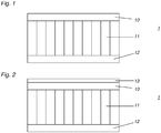
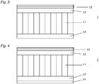
- the Fig. 1 to 4 each show a side view of a composite panel 1, with an upper metallic cover layer 10, comprising aluminum, a lower metallic cover layer 12 comprising aluminum and a metallic hollow chamber plate 11 arranged therebetween, comprising aluminum.
- the individual layers 10, 11, 12 are glued together.
- a coating 13 This is in the embodiment of Fig. 2 single layer and in the embodiments of the 3 and 4 three layers.
- the embodiment of Fig. 4 additionally contains a coating 14 on the lower metallic cover layer 12.
- the upper cover layer 10 is provided with a PVDF coating which on the one hand increases the scratch resistance, on the other hand is more hydrophobic than the metallic cover layer 10.
- the individual layers of the three-layer coating 13 each have PVDF. Also on the lower cover layer 12 such a coating 14 could be provided ( Fig. 4 ).
- the surface could also be e.g. in RAL optionally 9016, 1013 or 1015, and have a reflectance of at least 60%.
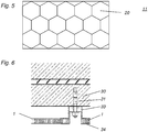
- FIG. 5 is the cross section through the hollow chamber plate 11 of the embodiments of Fig. 1 to 4 shown.
- This hollow chamber plate 11 is formed as a honeycomb panel, ie, the individual chambers 20 are formed in cross section as a regular hexagon and cylindrical.
- the upper cover layer 10 and the lower cover layer 12 are made of an aluminum alloy according to EN AW 5754 according to DIN EN 573-3: 2009.
- the thickness of the respective cover layer 10, 12 is in each case 1 mm.
- the hollow chamber plate 11 consists of an aluminum alloy according to EN AW 3005 according to DIN EN 573-3: 2009 at a thickness of 8 mm.
- the total thickness of the composite panel is therefore 10 mm and the basis weight is 6.53 kg / m 2 .
- the composite panels 1 may for example have a format of 4000 mm x 1250 mm.
- the upper and lower cover layers 10, 12 are made of the aluminum alloy EN AW 5005 according to DIN EN 573-3: 2009, during the hollow chamber plate 11 consists of an aluminum alloy EN AW 3005 according to DIN EN 573-3: 2009, since this combination of materials is easy to shape.
- Such a composite panel 1 has a fire resistance of at least A2-s1, d0 or higher according to DIN EN 13501-1: 2010-01.
- a composite panel 1 is shown, which is fastened by means of a fastening anchor 31 to a concrete surface 30.
- the fastening anchor 31 forms with the holder 33 and the profile 34 in the form of a hat profile, which represents a clamping profile, a fastening for the composite plate 1.
- the holder 33 and the hat profile 34 form two U-shaped cross sections for receiving the composite panel 1. means a screw, the hat profile 34 pressed against the holder 33 and secured to the mounting anchor 31.
- the embodiment shown serves, for example, for the lateral attachment of two adjacent composite panels 1.
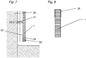
- Fig. 7 shows a composite plate 1, which is also secured by means of a fastening anchor 31 on a concrete surface 30.
- the fastening anchor 31, the holder 33 and the profile 34 receive the composite plate 1.
- a C or U-shaped profile 36 covers the composite panel 1 at the bottom or forms an edge cover.
- the C-shaped profile 36 can accommodate the composite panel 1 and with the fixing anchor 31 is also a wall mounting possible.
- the fastening anchors 31 are formed such that the composite plate 1 has a distance from the concrete surface 30.
- the concrete lining is ventilated. Should the concrete surface 30 nevertheless come into contact with water, the air circulation through the rear ventilation allows the concrete surface 30 to dry again.
- the surface of the tunnel lining is easier to clean, has greater brightness, is scratch resistant and protects the concrete lining of the tunnel.
- the aspect of easier cleanability is expressed by the fact that the concrete surface no longer needs to be cleaned with a tunnel brush, a very expensive and time-consuming process. It is sufficient for cleaning a simple vapor pressure jet, with which the surface is radiated. Also, the assembly of such composite panels 1 due to the low density of the hollow chamber plate 11 is very easy, since the mass of the composite plate 1 is low. In case of damage after an accident a simple replacement of the damaged composite panel 1 without a crane is possible. The composite plate 1 is also subject to almost no corrosion.
Landscapes
- Engineering & Computer Science (AREA)
- Architecture (AREA)
- Civil Engineering (AREA)
- Structural Engineering (AREA)
- Mining & Mineral Resources (AREA)
- Chemical & Material Sciences (AREA)
- Materials Engineering (AREA)
- Mechanical Engineering (AREA)
- Metallurgy (AREA)
- Organic Chemistry (AREA)
- Life Sciences & Earth Sciences (AREA)
- General Life Sciences & Earth Sciences (AREA)
- Geochemistry & Mineralogy (AREA)
- Geology (AREA)
- Lining And Supports For Tunnels (AREA)
Abstract
Description
- Die vorliegende Erfindung betrifft eine Tunnelauskleidung, die Verwendung einer Verbundplatte zur Auskleidung eines Tunnels sowie ein Verfahren zur Auskleidung eines Tunnels.
- Beim Bau von Tunneln wird nach Stand der Technik die Tunnellaibung mit Beton ausgekleidet. Bei Tunneln in Lagen mit alpinem Klima werden sowohl in der Sommerzeit, beispielsweise durch Regen, als auch in der Winterzeit, beispielsweise durch Schnee, große Mengen an Feuchtigkeit in den Tunnel eingetragen. Obwohl die Tunnellaibung keinen direkten Kontakt mit Schnee oder Regen hat, wird Nässe durch Kraftfahrzeuge und deren Räder aufgewirbelt, im Tunnel verteilt und kommt schlussendlich in direkten Kontakt mit der Oberfläche der Tunnelauskleidung.
- Durch die Verwirbelung der Feuchtigkeit in Verbindung mit auf dem Straßenbelag befindlichem Schmutz wird die Tunnelauskleidung stark verunreinigt. Der zusätzliche Einsatz von Streusalz oder Chemikalien zur Vorbeugung gegen Eisbildung führt zu chemisch aggressiven Mischungen, welche die Oberfläche der Tunnelauskleidung außerdem beschädigen. Wenngleich Beton gegen derartige Angriffe sehr beständig ist, wird die Betonoberfläche durch aggressive Mischungen aus Streusalz, Chemikalien, Feuchtigkeit und Schmutz im Laufe der Zeit verändert, was in weiterer Folge auch die Stahlarmierung im Beton angreifen kann. Durch die im Tunnel vorhandene hohe Konzentration an CO2 kann es zur Carbonatisierung des Betons kommen. Eine solche wäre aus Stabilitätsgründen nicht negativ anzusehen. Allerdings wird carbonatisierter Beton an der Oberfläche spröde, was dazu führt, dass nicht nur die Verschmutzung sondern auch Wasser tiefer eindringen kann. Dringt Wasser bis zur Stahlarmierung vor, können durch Korrosion des Stahls Spannungen im Beton entstehen, die im allerschlimmsten Fall zum Abplatzen des Betons führen können.
- Man ist daher dazu übergegangen, die Betonoberfläche mit Farbanstrichen zu versehen, welche einerseits die Reflexionseigenschaften verbessern und andererseits die Reinigung der Oberfläche durch hydrophobe Zusätze vereinfachen.
- Dennoch unterliegen auch solche Oberflächen immer noch einem Schädigungsprozess durch die oben geschilderten chemischen Vorgänge, der sich verlangsamen nicht aber vollständig aufhalten lässt. Je nach Verkehrsaufkommen und klimatischer Lage muss die Betonoberfläche nach 10 bis 20 Jahren einer kompletten Erneuerung unterzogen werden. Diese Erneuerung ist mit hohen Kosten und Ausfallszeiten des Tunnels verbunden. Alternative Lösungen wie in
EP 0 845 579 beschrieben, sehen Kunststoffauskleidungen des Tunnels vor, die allerdings nicht die gewünschten Standzeiten aufweisen. Die im Tunnel auftretenden Temperaturschwankungen verursachen bei Kunststoffauskleidungen eine rasche Materialermüdung. - Es besteht daher ein Bedarf, die Intervalle zwischen den Erneuerungen der Betonauskleidung in einem Tunnel zu erhöhen.
- Aufgabe der vorliegenden Erfindung ist es daher, das Intervall zwischen zwei Erneuerungen der Betonauskleidung eines Tunnels zu vergrößern.
- Gelöst wird diese Aufgabe durch eine Tunnelauskleidung, gekennzeichnet durch eine Verbundplatte aufweisend
- (i) eine obere metallische Decklage, umfassend Aluminium,
- (ii) eine untere metallische Decklage, umfassend Aluminium und
- (iii) eine dazwischen angeordnete metallische Hohlkammerplatte, umfassend Aluminium.
- Weiters wird die Aufgabe gelöst durch die Verwendung einer Verbundplatte, umfassend
- (i) eine obere metallische Decklage, umfassend Aluminium,
- (ii) eine untere metallische Decklage, umfassend Aluminium und
- (iii) eine dazwischen angeordnete metallische Hohlkammerplatte, umfassend Aluminium
- Schließlich wird die Aufgabe gelöst durch ein Verfahren zur Auskleidung eines mit Beton ummantelten Tunnels, wobei mehrere Befestigungsanker auf der Betonoberfläche einer Tunnellaibung eingebracht und eine Verbundplatte an den Befestigungsankern befestigt werden, dadurch gekennzeichnet, dass die Verbundplatte,
- (i) eine obere metallische Decklage, umfassend Aluminium,
- (ii) eine untere metallische Decklage, umfassend Aluminium und
- (iii) eine dazwischen angeordnete metallische Hohlkammerplatte, umfassend Aluminium
- Es hat sich gezeigt, dass die Verwendung einer solchen Verbundplatte zur Auskleidung eines Tunnels den Zeitraum zwischen der Herstellung und der Erneuerung einer Betonauskleidung im Tunnel um etliche Jahre verzögern kann. Durch das Aufbringen der Verbundplatte wird einerseits die bestehende Betonauskleidung von den aggressiven Gemischen, die im Tunnel entstehen, abgeschirmt, sodass die Betonauskleidung beinahe unversehrt bleibt und nur im Bereich von Leckagen einer Belastung unterliegt. Andererseits hat die Verbundplatte den großen Vorteil, dass sie leicht gereinigt werden kann. So kann sie bei entsprechender farblicher Gestaltung der Oberfläche mit einem hohen Reflexionsgrad auch die Verkehrssicherheit im Tunnel erhöhen.
- Bislang hat man im Tunnelbau Betonauskleidungen aus Metallen vermieden. Kostengünstige Metallverkleidungen unterliegen der Korrosion und inerte Metalle sind meist zu teuer, sodass eine Metallverkleidung vom Fachmann nicht in Erwägung gezogen wird. Außerdem weisen Metallverkleidungen eine hohe Masse auf, was die Verankerung an der Tunnellaibung erschwert und ein Sicherheitsrisiko darstellen kann, falls sich die Verankerung lösen sollte. Weiters ist bekannt, dass die Unterschiede in den Längenausdehnungskoeffizienten von Metallen und Beton eine Auskleidung nicht zulassen, da gerade in Tunneln häufig ein Wechsel zwischen kalten und warmen Temperaturen stattfindet und große Temperaturgradienten zwischen Tunnelinnerem, Erdreich und Auskleidung auftreten können.
- Durch den speziellen Aufbau der Verbundplatte mit oberer Decklage, unterer Decklage sowie dazwischen angeordneter Hohlkammerlage, jeweils umfassend Aluminium, konnten die beschriebenen Probleme gelöst werden.
- Insgesamt ist es daher überraschend, dass eine Verbundplatte - wie oben beschrieben - als Tunnelauskleidung all diese Probleme umgeht, wohingegen man der Meinung war, dass Metallauskleidungen oder Verbundauskleidungen ungeeignet sind. Die gegenständliche Erfindung unterliegt nämlich nicht der raschen Materialermüdung durch den Wechsel von Wärme und Kälte wie Kunststoffverbundauskleidungen und sie ist darüber hinaus auch - im Unterschied zu Kunststoffverbundplatten - äußerst brandsicher.
- In einer bevorzugten Ausführungsvariante ist vorgesehen, dass die Hohlkammerplatte als Honigwabenpaneel ausgebildet ist. Ein Honigwabenpaneel weist - wie der Name besagt - Kammern mit regelmäßigen, nebeneinander angeordneten regelmäßigen sechseckigen Zylindern auf, d.h. die Seitenkanten schließen jeweils einen Winkel von 120° miteinander ein. Die Seitenkantenlängen betragen bevorzugt zwischen 2 und 6 mm, da so eine besonders hohe Stabilität erzielt werden kann. Die Dicke der Kammerwände beträgt bevorzugt zwischen 40 und 60 µm.
- Die obere Decklage und die untere Decklage weisen bevorzugt eine Stärke von 0,7 mm bis 1,2 mm, vorzugsweise rund 1 mm auf.
- Die obere metallische Decklage, umfassend Aluminium und/oder die untere metallische Decklage, umfassend Aluminium und/oder die dazwischen angeordnete metallische Hohlkammerplatte, umfassend Aluminium, können aus Aluminium bestehen, wobei allerdings vorteilhaft ist, wenn die metallischen Komponenten aluminiumhältige Legierungen sind. Auch können die einzelnen Lagen aus demselben Metall bestehen. Bevorzugt ist allerdings, dass die Lagen aus unterschiedlichen Metallen bestehen. Beispielsweise kann die metallische Hohlkammerplatte eine Aluminiumlegierung mit über 90, vorzugsweise über 94 Gew.% Al umfassen. Ein Beispiel wäre die Legierung EN AW-3005 gemäß DIN EN 573-3:2009. Die Decklagen können zum Beispiel eine Aluminiumlegierung mit über 90, vorzugsweise über 94 Gew.% Al umfassen. Ein Beispiel wäre die Legierung EN AW-5754 gemäß DIN EN 573-3:2009. Ein weiteres Beispiel wäre die Legierung EN AW-5005 gemäß DIN EN 573-3:2009.
- Die drei Lagen sind miteinander verklebt. Der eingesetzte Klebstoff ist bevorzugt ein nichtbrennbarer Klebstoff, um die Brandsicherheit zu erhöhen.
- Die Passivierung von Aluminium führt einerseits dazu, dass der Korrosionsprozess deutlich verlangsamt ist, andererseits wird die Oberfläche spröder und dadurch schmutzempfindlicher. Eine Ausführungsvariante sieht daher eine zusätzliche nichtmetallische Beschichtung an der Decklage vor, wodurch die metallischen Lagen weniger verschmutzen sowie leichter zu reinigen sind und weniger leicht zerkratzen. In einer Ausführungsvariante ist daher vorgesehen, dass die obere Decklage eine die Kratzfestigkeit erhöhende Beschichtung aufweist. Weiters kann auch vorgesehen sein, dass die untere Decklage eine Beschichtung aufweist.
- Eine Beschichtung schützt die Aluminiumlagen noch besser, gewährleistet eine leichtere Reinigung und kann außerdem zur optischen Gestaltung verwendet werden. Es wäre z.B. eine hydrophobe Beschichtung denkbar, d.h. eine Beschichtung, die hydrophober als Aluminium oder die Decklage ist. Eine solche Beschichtung könnte beispielsweise eine Lackschicht mit hydrophoben Bestandteilen sein.
- Eine derartige Beschichtung kann außerdem brandhemmende bzw. brandvermindernde Eigenschaften aufweisen, was bei einem Tunnelbrand, bei dem sehr hohe Temperaturen - mit einer damit einhergehenden raschen Oxidation von Aluminium - auftreten können, vorteilhaft ist.
- Eine Beschichtung, die all die genannten Eigenschaften erfüllt, wäre z.B. eine mit fluorierten Polymeren. Beispielsweise kann PVDF (Polyvinylidendifluorid) genannt werden, welches brandhemmend und kratzfest ist. Fluorierte Polymere sind außerdem hydrophob, sodass sie besonders leicht reinigbar sind.
- Die Beschichtung kann einlagig oder mehrlagig ausgebildet sein. Mit einer mehrlagigen, beispielsweise dreilagigen, Beschichtung können oft bessere Ergebnisse als mit einer gleichdicken einlagigen Beschichtung erreicht werden. Auch bei einer mehrlagigen Beschichtung ist es vorteilhaft, wenn eine oder alle Lagen ein fluoriertes Polymer, insbesondere PVDF, aufweisen.
- Da die Kanten der Verbundplatte in der Regel unbeschichtet sind, hat es sich als vorteilhaft erwiesen, wenn die Kanten mit einer Kantenabdeckung versehen sind. Die Kantenabdeckung kann gleichzeitig mit den Befestigungsankern die Halterung für die Verbundplatte bilden.
- Im einfachsten Fall ist die Verbundplatte plan. Aufgrund der Tunnellaibung kann es allerdings auch vorteilhaft sein, wenn die Verbundplatte dreidimensional geformt ist, um sich der Krümmung des Tunnels anzupassen.
- Bevorzugt erfolgt die Montage der Verbundplatte so, dass sie mit Abstand zur Betonoberfläche befestigt wird. Dies kann z.B. über die Befestigungsanker geschehen, die z.B. Distanzelemente aufweisen. Dadurch ist eine Hinterlüftung der Auskleidung gewährleistet, was zu einer besseren Austrocknung der Betonoberfläche führt.
- Nachfolgend werden anhand der Figuren und Figurenbeschreibung weitere Details und Vorteile der Erfindung gezeigt.
- Fig. 1 bis 4
- zeigen vier Ausführungsbeispiele einer Verbundplatte.
- Fig. 5
- zeigt den Querschnitt durch eine Hohlkammerplatte einer Verbundplatte gemäß den Ausführungsbeispielen der
Fig. 1 bis 4 . - Fig. 6
- zeigt eine Tunnelauskleidung einer Seitenwand mit zwei Verbundplatten samt seitlicher Befestigung.
- Fig. 7
- zeigt eine Tunnelauskleidung für eine Seitenwand und die Verankerung am Fuß der Verbundplatte mit der unteren Abdeckung.
- Fig. 8
- zeigt die Tunnelauskleidung der
Fig. 5 und die obere Abdeckung. - Die
Fig. 1 bis 4 zeigen jeweils eine Seitenansicht einer Verbundplatte 1, mit einer oberen metallischen Decklage 10, umfassend Aluminium, einer unteren metallischen Decklage 12, umfassend Aluminium und einer dazwischen angeordneten metallischen Hohlkammerplatte 11, umfassend Aluminium. Die einzelnen Lagen 10, 11, 12 sind miteinander verklebt. In den drei Ausführungsbeispielen derFig. 2 bis 4 ist auf der metallischen Decklage 10 noch zusätzlich eine Beschichtung 13 aufgebracht. Diese ist im Ausführungsbeispiel derFig. 2 einlagig und in den Ausführungsbeispielen derFig. 3 und 4 dreilagig ausgebildet. Das Ausführungsbeispiel derFig. 4 enthält zusätzlich noch eine Beschichtung 14 auf der unteren metallischen Decklage 12. - In den gezeigten Ausführungsbeispielen der
Fig. 2 bis 4 ist die obere Decklage 10 mit einer PVDF-Beschichtung versehen, die einerseits die Kratzfestigkeit erhöht, andererseits hydrophober als die metallische Decklage 10 ist. In den Beispielen derFig. 3 und 4 weisen die einzelnen Lagen der dreilagigen Beschichtung 13 jeweils PVDF auf. Auch auf der unteren Decklage 12 könnte eine solche Beschichtung 14 vorgesehen sein (Fig. 4 ). - Die Oberfläche könnte außerdem z.B. in RAL wahlweise 9016, 1013 oder 1015, gehalten sein und einen Reflexionsgrad von mind. 60% aufweisen.
- In der
Fig. 5 ist der Querschnitt durch die Hohlkammerplatte 11 der Ausführungsbeispiele derFig. 1 bis 4 gezeigt. Diese Hohlkammerplatte 11 ist als Honigwabenpaneel ausgebildet, d.h. die einzelnen Kammern 20 sind im Querschnitt als reguläres Hexagon ausgebildet und zylinderförmig. - Die obere Decklage 10 und die untere Decklage 12 bestehen aus einer Aluminiumlegierung gemäß EN AW 5754 gemäß DIN EN 573-3:2009. Die Dicke der jeweiligen Decklage 10, 12 beträgt jeweils 1 mm. Die Hohlkammerplatte 11 besteht aus einer Aluminiumlegierung gemäß EN AW 3005 gemäß DIN EN 573-3:2009 bei einer Dicke von 8 mm. Die Gesamtdicke der Verbundplatte beträgt daher 10 mm und das Flächengewicht liegt bei 6,53 kg/m2. Die Verbundplatten 1 können z.B. ein Format von 4000 mm x 1250 mm aufweisen.
- In Ausführungsbeispielen, in denen die Verbundplatte 1 dreidimensional geformt ist und einen Biegung aufweist, hat es sich als vorteilhaft erwiesen, wenn die obere und die untere Decklage 10, 12 aus der Aluminiumlegierung EN AW 5005 gemäß DIN EN 573-3:2009 besteht, während die Hohlkammerplatte 11 aus einer Aluminiumlegierung EN AW 3005 gemäß DIN EN 573-3:2009 besteht, da diese Materialkombination gut formbar ist.
- Eine solche Verbundplatte 1 hat eine Brandbeständigkeit von mindestens A2-s1, d0 oder höher nach DIN EN 13501-1:2010-01.
- In
Fig. 6 ist eine Verbundplatte 1 gezeigt, die mittels eines Befestigungsankers 31 an einer Betonfläche 30 befestigt ist. Der Befestigungsanker 31 bildet mit der Halterung 33 und dem Profil 34 in Form eines Hutprofils, welches ein Klemmprofil darstellt, eine Befestigung für die Verbundplatte 1. Dabei bilden die Halterung 33 und das Hutprofil 34 zwei U-förmige Querschnitte zur Aufnahme der Verbundplatte 1. Mittels einer Schraubverbindung kann das Hutprofil 34 gegen die Halterung 33 gepresst und am Befestigungsanker 31 befestigt werden. Die gezeigte Ausführungsform dient z.B. zur seitlichen Befestigung von zwei benachbarten Verbundplatten 1. -
Fig. 7 zeigt eine Verbundplatte 1, die ebenfalls mittels eines Befestigungsankers 31 an einer Betonfläche 30 befestigt ist. Der Befestigungsanker 31, die Halterung 33 und das Profil 34 nehmen die Verbundplatte 1 auf. Ein C bzw. U- förmiges Profil 36 deckt die Verbundplatte 1 an der Unterseite ab bzw. bildet eine Kantenabdeckung. Das C-förmige Profil 36 kann die Verbundplatte 1 aufnehmen und mit dem Befestigungsanker 31 ist auch eine Wandmontage möglich. Weiters kann - wie inFig. 8 dargestellt - auch an der Oberseite der Verbundplatte 1 ein C-förmiges Profil 36 vorgesehen sein, welches als Kantenabdeckung dient. Mit dem Profil 36 könnte die Verbundplatte 1 aber u.U. auch an der Halterung befestigt werden. - In den gezeigten Ausführungsbeispielen sind die Befestigungsanker 31 derart ausgebildet, dass die Verbundplatte 1 einen Abstand zur Betonoberfläche 30 aufweist. Dadurch ist die Betonauskleidung hinterlüftet. Sollte die Betonoberfläche 30 trotzdem mit Wasser in Kontakt kommen, erlaubt die Luftzirkulation durch die Hinterlüftung, dass die Betonoberfläche 30 wieder trocknet.
- Gegenüber dem Stand der Technik hat die vorliegende Erfindung zahlreiche Vorteile. Die Oberfläche der Tunnelauskleidung lässt sich leichter reinigen, sie weist eine größere Helligkeit auf, sie ist kratzfest und sie schützt die Betonauskleidung des Tunnels.
- Der Aspekt der leichteren Reinigbarkeit äußert sich dadurch, dass die Betonoberfläche nicht mehr mit einer Tunnelbürste gereinigt werden muss, einem sehr teueren und zeitaufwändigen Verfahren. Es reicht zum Reinigen ein einfacher Dampfdruckstrahler, mit welchem die Oberfläche abgestrahlt wird. Auch ist die Montage solcher Verbundplatten 1 aufgrund der niedrigen Dichte der Hohlkammerplatte 11 sehr einfach, da die Masse der Verbundplatte 1 gering ist. Im Falle einer Beschädigung nach einem Unfall ist ein einfacher Austausch der beschädigten Verbundplatte 1 ohne Kran möglich. Die Verbundplatte 1 unterliegt außerdem fast keiner Korrosion.
- Die Möglichkeit der Oberflächengestaltung mit hellen Farben erlaubt besser ausleuchtbare Tunnel und trotz geringer Dicke der Verbundplatte ist gute Brandsicherheit gewährleistet
Claims (9)
- Tunnelauskleidung, gekennzeichnet durch eine Verbundplatte (1) umfassend(i) eine obere metallische Decklage (10), umfassend Aluminium,(ii) eine untere metallische Decklage (12), umfassend Aluminium und(iii) eine dazwischen angeordnete metallische Hohlkammerplatte (11), umfassend Aluminium.
- Verwendung einer Verbundplatte (1), umfassend(i) eine obere metallische Decklage (10), umfassend Aluminium,(ii) eine untere metallische Decklage (12), umfassend Aluminium und(iii) eine dazwischen angeordnete metallische Hohlkammerplatte (11), umfassend Aluminium zur Auskleidung eines Tunnels.
- Verfahren zur Auskleidung eines mit Beton ummantelten Tunnels, wobei mehrere Befestigungsanker (31) auf der Betonoberfläche (30) einer Tunnellaibung eingebracht und eine Verbundplatte (1) an den Befestigungsankern (31) befestigt werden, dadurch gekennzeichnet, dass die Verbundplatte (1),(i) eine obere metallische Decklage (10), umfassend Aluminium,(ii) eine untere metallische Decklage (12), umfassend Aluminium und(iii) eine dazwischen angeordnete metallische Hohlkammerplatte (11), umfassend Aluminium umfasst.
- Tunnelauskleidung nach Anspruch 1 oder Verwendung nach Anspruch 2 oder Verfahren nach Anspruch 3, dadurch gekennzeichnet, dass die Hohlkammerplatte (11) als Honigwabenpaneel ausgebildet ist.
- Tunnelauskleidung nach Anspruch 1 oder Anspruch 4, Verwendung nach Anspruch 2 oder Anspruch 4 oder Verfahren nach Anspruch 3 oder Anspruch 4, dadurch gekennzeichnet, dass die obere Decklage (10) eine hydrophobe Beschichtung aufweist.
- Tunnelauskleidung nach Anspruch 1, Anspruch 4 oder Anspruch 5, Verwendung nach Anspruch 2, Anspruch 4 oder Anspruch 5 oder Verfahren nach einem der Ansprüche 3 bis 5, dadurch gekennzeichnet, dass die untere Decklage (12) eine hydrophobe Beschichtung aufweist.
- Tunnelauskleidung nach Anspruch 5 oder 6, Verwendung nach Anspruch 5 oder 6 oder Verfahren nach Anspruch 5 oder 6, dadurch gekennzeichnet, dass die Beschichtung ein fluoriertes Polymer, vorzugweise PVDF, aufweist.
- Tunnelauskleidung nach einem der Ansprüche 1, 4 bis 7, Verwendung nach einem der Ansprüche 2, 4 bis 7 oder Verfahren nach einem der Ansprüche 3 bis 7, dadurch gekennzeichnet, dass die obere Decklage (10), die untere Decklage (12) und/oder die Hohlkammerplatte (11) eine Aluminiumlegierung umfassen.
- Tunnelauskleidung nach Anspruch 8, Verwendung nach Anspruch 8 oder Verfahren nach Anspruch 8, dadurch gekennzeichnet, dass die Aluminiumlegierung über 90 Gew.% Al, vorzugsweise über 95 Gew.% umfassen.
Priority Applications (1)
| Application Number | Priority Date | Filing Date | Title |
|---|---|---|---|
| EP17154655.9A EP3357680B1 (de) | 2017-02-03 | 2017-02-03 | Tunnelauskleidung |
Applications Claiming Priority (1)
| Application Number | Priority Date | Filing Date | Title |
|---|---|---|---|
| EP17154655.9A EP3357680B1 (de) | 2017-02-03 | 2017-02-03 | Tunnelauskleidung |
Publications (2)
| Publication Number | Publication Date |
|---|---|
| EP3357680A1 true EP3357680A1 (de) | 2018-08-08 |
| EP3357680B1 EP3357680B1 (de) | 2022-04-13 |
Family
ID=58094153
Family Applications (1)
| Application Number | Title | Priority Date | Filing Date |
|---|---|---|---|
| EP17154655.9A Active EP3357680B1 (de) | 2017-02-03 | 2017-02-03 | Tunnelauskleidung |
Country Status (1)
| Country | Link |
|---|---|
| EP (1) | EP3357680B1 (de) |
Cited By (1)
| Publication number | Priority date | Publication date | Assignee | Title |
|---|---|---|---|---|
| CN114961778A (zh) * | 2022-06-02 | 2022-08-30 | 青岛沙木新材料有限公司 | 具备仿生蜂窝结构的高阻尼地铁隧道内衬结构 |
Citations (6)
| Publication number | Priority date | Publication date | Assignee | Title |
|---|---|---|---|---|
| US5510597A (en) * | 1993-09-17 | 1996-04-23 | Alusuisse-Lonza Services Ltd. | Welded composite panels |
| JPH10121896A (ja) * | 1996-10-25 | 1998-05-12 | Ykk Architect Prod Kk | 地下構造物用壁面パネル |
| EP0845579A1 (de) | 1996-12-02 | 1998-06-03 | Xaver Jehle | Tunnelauskleidung |
| JP2000280089A (ja) * | 1999-03-30 | 2000-10-10 | Nippon Light Metal Co Ltd | 高強度アルミニウム合金合わせ板およびアルミニウム合金製ろう付け体 |
| CN1302727A (zh) * | 2000-01-06 | 2001-07-11 | 深圳方大意德新材料有限公司 | 蜂窝复合板 |
| CN2595920Y (zh) * | 2002-12-18 | 2003-12-31 | 林建伟 | 多层复合铝墙板 |
Family Cites Families (1)
| Publication number | Priority date | Publication date | Assignee | Title |
|---|---|---|---|---|
| JPS58216758A (ja) * | 1982-06-09 | 1983-12-16 | Kansai Paint Co Ltd | 汚染防止塗膜の形成法 |
-
2017
- 2017-02-03 EP EP17154655.9A patent/EP3357680B1/de active Active
Patent Citations (6)
| Publication number | Priority date | Publication date | Assignee | Title |
|---|---|---|---|---|
| US5510597A (en) * | 1993-09-17 | 1996-04-23 | Alusuisse-Lonza Services Ltd. | Welded composite panels |
| JPH10121896A (ja) * | 1996-10-25 | 1998-05-12 | Ykk Architect Prod Kk | 地下構造物用壁面パネル |
| EP0845579A1 (de) | 1996-12-02 | 1998-06-03 | Xaver Jehle | Tunnelauskleidung |
| JP2000280089A (ja) * | 1999-03-30 | 2000-10-10 | Nippon Light Metal Co Ltd | 高強度アルミニウム合金合わせ板およびアルミニウム合金製ろう付け体 |
| CN1302727A (zh) * | 2000-01-06 | 2001-07-11 | 深圳方大意德新材料有限公司 | 蜂窝复合板 |
| CN2595920Y (zh) * | 2002-12-18 | 2003-12-31 | 林建伟 | 多层复合铝墙板 |
Non-Patent Citations (2)
| Title |
|---|
| DIN EN 13501-1, January 2010 (2010-01-01) |
| DIN EN 573-3, 2009 |
Cited By (1)
| Publication number | Priority date | Publication date | Assignee | Title |
|---|---|---|---|---|
| CN114961778A (zh) * | 2022-06-02 | 2022-08-30 | 青岛沙木新材料有限公司 | 具备仿生蜂窝结构的高阻尼地铁隧道内衬结构 |
Also Published As
| Publication number | Publication date |
|---|---|
| EP3357680B1 (de) | 2022-04-13 |
Similar Documents
| Publication | Publication Date | Title |
|---|---|---|
| AT406064B (de) | Bauelement | |
| DE2528207A1 (de) | Faserverstaerkte platte und verfahren zu ihrer herstellung | |
| EP2088253A2 (de) | Brandschutzriegelelement | |
| DE102014000316A1 (de) | Hochleistungsbewehrter Beton | |
| DE2930123A1 (de) | Schallschluckende bauplatte | |
| EP2726680B1 (de) | FASSADENKONSTRUKTION ZUR WÄRMEDÄMMUNG UND VERKLEIDUNG VON GEBÄUDEAUßENWÄNDEN SOWIE VERFAHREN ZUR HERSTELLUNG EINER SOLCHEN FASSADENKONSTRUKTION | |
| DE19828607A1 (de) | Verfahren zum Verstärken von Stahl- und Spannbetonbauteilen | |
| EP3357680B1 (de) | Tunnelauskleidung | |
| DE202017104261U1 (de) | Rückbaufähiges Wärmedämmverbundsystem | |
| EP0832335B1 (de) | Schalungstafel aus beton | |
| EP2402522A2 (de) | Bau- und/oder Wärmedämmplatte sowie Wärmedämmverbundsystem mit entsprechender Platte | |
| DE202010000245U1 (de) | Schallabsorberelement zum Einbau in eine Brandschutzkonstruktion aus Brandschutzplatten | |
| EP3926117B1 (de) | Wärmedämmverbundsystem, fassade mit dem wärmedämmverbundsystem sowie verfahren zur errichtung desselben | |
| EP0201757A3 (de) | Fassadenbekleidung, insbesondere zur Sanierung von Altbauten | |
| DE69632048T2 (de) | Gegen hohe temperaturen beständiges isolationselement | |
| EP1111289A2 (de) | Wärme- und/oder Schalldämmung für eine ebene Fläche und Verfahren zur Befestigung von Dämmstoffplatten bzw. Dämmstoffplattenabschnitten auf ebenen Flächen | |
| DE29915463U1 (de) | Dämmelement zur Wärme- und/oder Schalldämmung von Gebäudewänden | |
| DE19860993C2 (de) | Dämmstoffelement | |
| DE896860C (de) | In sich vorgespanntes Bewehrungselement aus Formsteinen | |
| AT396805B (de) | Bauelement | |
| EP1790788B1 (de) | Brandschutzbekleidung einer Wand und/oder Decke aus Beton | |
| DE102016219222A1 (de) | Gebäudewand mit wärmegedämmter Fassadenverkleidung | |
| EP1299601A1 (de) | Bauelement zur abdichtung von flachdächern | |
| DE202012102463U1 (de) | Befestigungsprofil | |
| DE202005021203U1 (de) | Decken- oder Wandelement |
Legal Events
| Date | Code | Title | Description |
|---|---|---|---|
| PUAI | Public reference made under article 153(3) epc to a published international application that has entered the european phase |
Free format text: ORIGINAL CODE: 0009012 |
|
| STAA | Information on the status of an ep patent application or granted ep patent |
Free format text: STATUS: THE APPLICATION HAS BEEN PUBLISHED |
|
| AK | Designated contracting states |
Kind code of ref document: A1 Designated state(s): AL AT BE BG CH CY CZ DE DK EE ES FI FR GB GR HR HU IE IS IT LI LT LU LV MC MK MT NL NO PL PT RO RS SE SI SK SM TR |
|
| AX | Request for extension of the european patent |
Extension state: BA ME |
|
| STAA | Information on the status of an ep patent application or granted ep patent |
Free format text: STATUS: REQUEST FOR EXAMINATION WAS MADE |
|
| 17P | Request for examination filed |
Effective date: 20190205 |
|
| RBV | Designated contracting states (corrected) |
Designated state(s): AL AT BE BG CH CY CZ DE DK EE ES FI FR GB GR HR HU IE IS IT LI LT LU LV MC MK MT NL NO PL PT RO RS SE SI SK SM TR |
|
| STAA | Information on the status of an ep patent application or granted ep patent |
Free format text: STATUS: EXAMINATION IS IN PROGRESS |
|
| 17Q | First examination report despatched |
Effective date: 20200130 |
|
| GRAP | Despatch of communication of intention to grant a patent |
Free format text: ORIGINAL CODE: EPIDOSNIGR1 |
|
| STAA | Information on the status of an ep patent application or granted ep patent |
Free format text: STATUS: GRANT OF PATENT IS INTENDED |
|
| INTG | Intention to grant announced |
Effective date: 20211208 |
|
| GRAS | Grant fee paid |
Free format text: ORIGINAL CODE: EPIDOSNIGR3 |
|
| GRAA | (expected) grant |
Free format text: ORIGINAL CODE: 0009210 |
|
| STAA | Information on the status of an ep patent application or granted ep patent |
Free format text: STATUS: THE PATENT HAS BEEN GRANTED |
|
| AK | Designated contracting states |
Kind code of ref document: B1 Designated state(s): AL AT BE BG CH CY CZ DE DK EE ES FI FR GB GR HR HU IE IS IT LI LT LU LV MC MK MT NL NO PL PT RO RS SE SI SK SM TR |
|
| REG | Reference to a national code |
Ref country code: GB Ref legal event code: FG4D Free format text: NOT ENGLISH |
|
| REG | Reference to a national code |
Ref country code: CH Ref legal event code: EP |
|
| REG | Reference to a national code |
Ref country code: DE Ref legal event code: R096 Ref document number: 502017012942 Country of ref document: DE |
|
| REG | Reference to a national code |
Ref country code: IE Ref legal event code: FG4D Free format text: LANGUAGE OF EP DOCUMENT: GERMAN |
|
| REG | Reference to a national code |
Ref country code: AT Ref legal event code: REF Ref document number: 1483083 Country of ref document: AT Kind code of ref document: T Effective date: 20220515 |
|
| REG | Reference to a national code |
Ref country code: LT Ref legal event code: MG9D |
|
| REG | Reference to a national code |
Ref country code: NL Ref legal event code: MP Effective date: 20220413 |
|
| PG25 | Lapsed in a contracting state [announced via postgrant information from national office to epo] |
Ref country code: NL Free format text: LAPSE BECAUSE OF FAILURE TO SUBMIT A TRANSLATION OF THE DESCRIPTION OR TO PAY THE FEE WITHIN THE PRESCRIBED TIME-LIMIT Effective date: 20220413 |
|
| PG25 | Lapsed in a contracting state [announced via postgrant information from national office to epo] |
Ref country code: SE Free format text: LAPSE BECAUSE OF FAILURE TO SUBMIT A TRANSLATION OF THE DESCRIPTION OR TO PAY THE FEE WITHIN THE PRESCRIBED TIME-LIMIT Effective date: 20220413 Ref country code: PT Free format text: LAPSE BECAUSE OF FAILURE TO SUBMIT A TRANSLATION OF THE DESCRIPTION OR TO PAY THE FEE WITHIN THE PRESCRIBED TIME-LIMIT Effective date: 20220816 Ref country code: NO Free format text: LAPSE BECAUSE OF FAILURE TO SUBMIT A TRANSLATION OF THE DESCRIPTION OR TO PAY THE FEE WITHIN THE PRESCRIBED TIME-LIMIT Effective date: 20220713 Ref country code: LT Free format text: LAPSE BECAUSE OF FAILURE TO SUBMIT A TRANSLATION OF THE DESCRIPTION OR TO PAY THE FEE WITHIN THE PRESCRIBED TIME-LIMIT Effective date: 20220413 Ref country code: HR Free format text: LAPSE BECAUSE OF FAILURE TO SUBMIT A TRANSLATION OF THE DESCRIPTION OR TO PAY THE FEE WITHIN THE PRESCRIBED TIME-LIMIT Effective date: 20220413 Ref country code: GR Free format text: LAPSE BECAUSE OF FAILURE TO SUBMIT A TRANSLATION OF THE DESCRIPTION OR TO PAY THE FEE WITHIN THE PRESCRIBED TIME-LIMIT Effective date: 20220714 Ref country code: FI Free format text: LAPSE BECAUSE OF FAILURE TO SUBMIT A TRANSLATION OF THE DESCRIPTION OR TO PAY THE FEE WITHIN THE PRESCRIBED TIME-LIMIT Effective date: 20220413 Ref country code: ES Free format text: LAPSE BECAUSE OF FAILURE TO SUBMIT A TRANSLATION OF THE DESCRIPTION OR TO PAY THE FEE WITHIN THE PRESCRIBED TIME-LIMIT Effective date: 20220413 Ref country code: BG Free format text: LAPSE BECAUSE OF FAILURE TO SUBMIT A TRANSLATION OF THE DESCRIPTION OR TO PAY THE FEE WITHIN THE PRESCRIBED TIME-LIMIT Effective date: 20220713 |
|
| PG25 | Lapsed in a contracting state [announced via postgrant information from national office to epo] |
Ref country code: RS Free format text: LAPSE BECAUSE OF FAILURE TO SUBMIT A TRANSLATION OF THE DESCRIPTION OR TO PAY THE FEE WITHIN THE PRESCRIBED TIME-LIMIT Effective date: 20220413 Ref country code: PL Free format text: LAPSE BECAUSE OF FAILURE TO SUBMIT A TRANSLATION OF THE DESCRIPTION OR TO PAY THE FEE WITHIN THE PRESCRIBED TIME-LIMIT Effective date: 20220413 Ref country code: LV Free format text: LAPSE BECAUSE OF FAILURE TO SUBMIT A TRANSLATION OF THE DESCRIPTION OR TO PAY THE FEE WITHIN THE PRESCRIBED TIME-LIMIT Effective date: 20220413 Ref country code: IS Free format text: LAPSE BECAUSE OF FAILURE TO SUBMIT A TRANSLATION OF THE DESCRIPTION OR TO PAY THE FEE WITHIN THE PRESCRIBED TIME-LIMIT Effective date: 20220813 |
|
| REG | Reference to a national code |
Ref country code: DE Ref legal event code: R097 Ref document number: 502017012942 Country of ref document: DE |
|
| PG25 | Lapsed in a contracting state [announced via postgrant information from national office to epo] |
Ref country code: SM Free format text: LAPSE BECAUSE OF FAILURE TO SUBMIT A TRANSLATION OF THE DESCRIPTION OR TO PAY THE FEE WITHIN THE PRESCRIBED TIME-LIMIT Effective date: 20220413 Ref country code: SK Free format text: LAPSE BECAUSE OF FAILURE TO SUBMIT A TRANSLATION OF THE DESCRIPTION OR TO PAY THE FEE WITHIN THE PRESCRIBED TIME-LIMIT Effective date: 20220413 Ref country code: RO Free format text: LAPSE BECAUSE OF FAILURE TO SUBMIT A TRANSLATION OF THE DESCRIPTION OR TO PAY THE FEE WITHIN THE PRESCRIBED TIME-LIMIT Effective date: 20220413 Ref country code: EE Free format text: LAPSE BECAUSE OF FAILURE TO SUBMIT A TRANSLATION OF THE DESCRIPTION OR TO PAY THE FEE WITHIN THE PRESCRIBED TIME-LIMIT Effective date: 20220413 Ref country code: DK Free format text: LAPSE BECAUSE OF FAILURE TO SUBMIT A TRANSLATION OF THE DESCRIPTION OR TO PAY THE FEE WITHIN THE PRESCRIBED TIME-LIMIT Effective date: 20220413 Ref country code: CZ Free format text: LAPSE BECAUSE OF FAILURE TO SUBMIT A TRANSLATION OF THE DESCRIPTION OR TO PAY THE FEE WITHIN THE PRESCRIBED TIME-LIMIT Effective date: 20220413 |
|
| PLBE | No opposition filed within time limit |
Free format text: ORIGINAL CODE: 0009261 |
|
| STAA | Information on the status of an ep patent application or granted ep patent |
Free format text: STATUS: NO OPPOSITION FILED WITHIN TIME LIMIT |
|
| 26N | No opposition filed |
Effective date: 20230116 |
|
| PG25 | Lapsed in a contracting state [announced via postgrant information from national office to epo] |
Ref country code: AL Free format text: LAPSE BECAUSE OF FAILURE TO SUBMIT A TRANSLATION OF THE DESCRIPTION OR TO PAY THE FEE WITHIN THE PRESCRIBED TIME-LIMIT Effective date: 20220413 |
|
| PG25 | Lapsed in a contracting state [announced via postgrant information from national office to epo] |
Ref country code: SI Free format text: LAPSE BECAUSE OF FAILURE TO SUBMIT A TRANSLATION OF THE DESCRIPTION OR TO PAY THE FEE WITHIN THE PRESCRIBED TIME-LIMIT Effective date: 20220413 |
|
| P01 | Opt-out of the competence of the unified patent court (upc) registered |
Effective date: 20230512 |
|
| PG25 | Lapsed in a contracting state [announced via postgrant information from national office to epo] |
Ref country code: MC Free format text: LAPSE BECAUSE OF FAILURE TO SUBMIT A TRANSLATION OF THE DESCRIPTION OR TO PAY THE FEE WITHIN THE PRESCRIBED TIME-LIMIT Effective date: 20220413 |
|
| REG | Reference to a national code |
Ref country code: BE Ref legal event code: MM Effective date: 20230228 |
|
| GBPC | Gb: european patent ceased through non-payment of renewal fee |
Effective date: 20230203 |
|
| PG25 | Lapsed in a contracting state [announced via postgrant information from national office to epo] |
Ref country code: LU Free format text: LAPSE BECAUSE OF NON-PAYMENT OF DUE FEES Effective date: 20230203 |
|
| REG | Reference to a national code |
Ref country code: IE Ref legal event code: MM4A |
|
| PG25 | Lapsed in a contracting state [announced via postgrant information from national office to epo] |
Ref country code: GB Free format text: LAPSE BECAUSE OF NON-PAYMENT OF DUE FEES Effective date: 20230203 |
|
| PG25 | Lapsed in a contracting state [announced via postgrant information from national office to epo] |
Ref country code: IT Free format text: LAPSE BECAUSE OF FAILURE TO SUBMIT A TRANSLATION OF THE DESCRIPTION OR TO PAY THE FEE WITHIN THE PRESCRIBED TIME-LIMIT Effective date: 20220413 Ref country code: IE Free format text: LAPSE BECAUSE OF NON-PAYMENT OF DUE FEES Effective date: 20230203 Ref country code: GB Free format text: LAPSE BECAUSE OF NON-PAYMENT OF DUE FEES Effective date: 20230203 Ref country code: FR Free format text: LAPSE BECAUSE OF NON-PAYMENT OF DUE FEES Effective date: 20230228 |
|
| PG25 | Lapsed in a contracting state [announced via postgrant information from national office to epo] |
Ref country code: BE Free format text: LAPSE BECAUSE OF NON-PAYMENT OF DUE FEES Effective date: 20230228 |
|
| PG25 | Lapsed in a contracting state [announced via postgrant information from national office to epo] |
Ref country code: BG Free format text: LAPSE BECAUSE OF FAILURE TO SUBMIT A TRANSLATION OF THE DESCRIPTION OR TO PAY THE FEE WITHIN THE PRESCRIBED TIME-LIMIT Effective date: 20220413 |
|
| PG25 | Lapsed in a contracting state [announced via postgrant information from national office to epo] |
Ref country code: BG Free format text: LAPSE BECAUSE OF FAILURE TO SUBMIT A TRANSLATION OF THE DESCRIPTION OR TO PAY THE FEE WITHIN THE PRESCRIBED TIME-LIMIT Effective date: 20220413 |
|
| PGFP | Annual fee paid to national office [announced via postgrant information from national office to epo] |
Ref country code: DE Payment date: 20250218 Year of fee payment: 9 |
|
| PGFP | Annual fee paid to national office [announced via postgrant information from national office to epo] |
Ref country code: CH Payment date: 20250301 Year of fee payment: 9 Ref country code: AT Payment date: 20250221 Year of fee payment: 9 |
|
| PG25 | Lapsed in a contracting state [announced via postgrant information from national office to epo] |
Ref country code: CY Free format text: LAPSE BECAUSE OF FAILURE TO SUBMIT A TRANSLATION OF THE DESCRIPTION OR TO PAY THE FEE WITHIN THE PRESCRIBED TIME-LIMIT; INVALID AB INITIO Effective date: 20170203 |
|
| PG25 | Lapsed in a contracting state [announced via postgrant information from national office to epo] |
Ref country code: HU Free format text: LAPSE BECAUSE OF FAILURE TO SUBMIT A TRANSLATION OF THE DESCRIPTION OR TO PAY THE FEE WITHIN THE PRESCRIBED TIME-LIMIT; INVALID AB INITIO Effective date: 20170203 |
|
| PG25 | Lapsed in a contracting state [announced via postgrant information from national office to epo] |
Ref country code: TR Free format text: LAPSE BECAUSE OF FAILURE TO SUBMIT A TRANSLATION OF THE DESCRIPTION OR TO PAY THE FEE WITHIN THE PRESCRIBED TIME-LIMIT Effective date: 20220413 |