EP3354545B1 - Lichtmodul für fahrzeugscheinwerfer - Google Patents
Lichtmodul für fahrzeugscheinwerfer Download PDFInfo
- Publication number
- EP3354545B1 EP3354545B1 EP18153195.5A EP18153195A EP3354545B1 EP 3354545 B1 EP3354545 B1 EP 3354545B1 EP 18153195 A EP18153195 A EP 18153195A EP 3354545 B1 EP3354545 B1 EP 3354545B1
- Authority
- EP
- European Patent Office
- Prior art keywords
- light
- light emitting
- low beam
- section
- reflector
- Prior art date
- Legal status (The legal status is an assumption and is not a legal conclusion. Google has not performed a legal analysis and makes no representation as to the accuracy of the status listed.)
- Active
Links
Images


Classifications
-
- F—MECHANICAL ENGINEERING; LIGHTING; HEATING; WEAPONS; BLASTING
- F21—LIGHTING
- F21S—NON-PORTABLE LIGHTING DEVICES; SYSTEMS THEREOF; VEHICLE LIGHTING DEVICES SPECIALLY ADAPTED FOR VEHICLE EXTERIORS
- F21S41/00—Illuminating devices specially adapted for vehicle exteriors, e.g. headlamps
- F21S41/10—Illuminating devices specially adapted for vehicle exteriors, e.g. headlamps characterised by the light source
- F21S41/14—Illuminating devices specially adapted for vehicle exteriors, e.g. headlamps characterised by the light source characterised by the type of light source
- F21S41/141—Light emitting diodes [LED]
- F21S41/143—Light emitting diodes [LED] the main emission direction of the LED being parallel to the optical axis of the illuminating device
-
- B—PERFORMING OPERATIONS; TRANSPORTING
- B62—LAND VEHICLES FOR TRAVELLING OTHERWISE THAN ON RAILS
- B62J—CYCLE SADDLES OR SEATS; AUXILIARY DEVICES OR ACCESSORIES SPECIALLY ADAPTED TO CYCLES AND NOT OTHERWISE PROVIDED FOR, e.g. ARTICLE CARRIERS OR CYCLE PROTECTORS
- B62J6/00—Arrangement of optical signalling or lighting devices on cycles; Mounting or supporting thereof; Circuits therefor
- B62J6/02—Headlights
- B62J6/022—Headlights specially adapted for motorcycles or the like
- B62J6/024—Switching between high and low beam
-
- F—MECHANICAL ENGINEERING; LIGHTING; HEATING; WEAPONS; BLASTING
- F21—LIGHTING
- F21S—NON-PORTABLE LIGHTING DEVICES; SYSTEMS THEREOF; VEHICLE LIGHTING DEVICES SPECIALLY ADAPTED FOR VEHICLE EXTERIORS
- F21S41/00—Illuminating devices specially adapted for vehicle exteriors, e.g. headlamps
- F21S41/10—Illuminating devices specially adapted for vehicle exteriors, e.g. headlamps characterised by the light source
- F21S41/14—Illuminating devices specially adapted for vehicle exteriors, e.g. headlamps characterised by the light source characterised by the type of light source
- F21S41/141—Light emitting diodes [LED]
- F21S41/151—Light emitting diodes [LED] arranged in one or more lines
-
- F—MECHANICAL ENGINEERING; LIGHTING; HEATING; WEAPONS; BLASTING
- F21—LIGHTING
- F21S—NON-PORTABLE LIGHTING DEVICES; SYSTEMS THEREOF; VEHICLE LIGHTING DEVICES SPECIALLY ADAPTED FOR VEHICLE EXTERIORS
- F21S41/00—Illuminating devices specially adapted for vehicle exteriors, e.g. headlamps
- F21S41/10—Illuminating devices specially adapted for vehicle exteriors, e.g. headlamps characterised by the light source
- F21S41/14—Illuminating devices specially adapted for vehicle exteriors, e.g. headlamps characterised by the light source characterised by the type of light source
- F21S41/141—Light emitting diodes [LED]
- F21S41/155—Surface emitters, e.g. organic light emitting diodes [OLED]
-
- F—MECHANICAL ENGINEERING; LIGHTING; HEATING; WEAPONS; BLASTING
- F21—LIGHTING
- F21S—NON-PORTABLE LIGHTING DEVICES; SYSTEMS THEREOF; VEHICLE LIGHTING DEVICES SPECIALLY ADAPTED FOR VEHICLE EXTERIORS
- F21S41/00—Illuminating devices specially adapted for vehicle exteriors, e.g. headlamps
- F21S41/20—Illuminating devices specially adapted for vehicle exteriors, e.g. headlamps characterised by refractors, transparent cover plates, light guides or filters
- F21S41/24—Light guides
-
- F—MECHANICAL ENGINEERING; LIGHTING; HEATING; WEAPONS; BLASTING
- F21—LIGHTING
- F21S—NON-PORTABLE LIGHTING DEVICES; SYSTEMS THEREOF; VEHICLE LIGHTING DEVICES SPECIALLY ADAPTED FOR VEHICLE EXTERIORS
- F21S41/00—Illuminating devices specially adapted for vehicle exteriors, e.g. headlamps
- F21S41/20—Illuminating devices specially adapted for vehicle exteriors, e.g. headlamps characterised by refractors, transparent cover plates, light guides or filters
- F21S41/25—Projection lenses
- F21S41/255—Lenses with a front view of circular or truncated circular outline
-
- F—MECHANICAL ENGINEERING; LIGHTING; HEATING; WEAPONS; BLASTING
- F21—LIGHTING
- F21S—NON-PORTABLE LIGHTING DEVICES; SYSTEMS THEREOF; VEHICLE LIGHTING DEVICES SPECIALLY ADAPTED FOR VEHICLE EXTERIORS
- F21S41/00—Illuminating devices specially adapted for vehicle exteriors, e.g. headlamps
- F21S41/20—Illuminating devices specially adapted for vehicle exteriors, e.g. headlamps characterised by refractors, transparent cover plates, light guides or filters
- F21S41/25—Projection lenses
- F21S41/265—Composite lenses; Lenses with a patch-like shape
-
- F—MECHANICAL ENGINEERING; LIGHTING; HEATING; WEAPONS; BLASTING
- F21—LIGHTING
- F21S—NON-PORTABLE LIGHTING DEVICES; SYSTEMS THEREOF; VEHICLE LIGHTING DEVICES SPECIALLY ADAPTED FOR VEHICLE EXTERIORS
- F21S41/00—Illuminating devices specially adapted for vehicle exteriors, e.g. headlamps
- F21S41/20—Illuminating devices specially adapted for vehicle exteriors, e.g. headlamps characterised by refractors, transparent cover plates, light guides or filters
- F21S41/25—Projection lenses
- F21S41/275—Lens surfaces, e.g. coatings or surface structures
-
- F—MECHANICAL ENGINEERING; LIGHTING; HEATING; WEAPONS; BLASTING
- F21—LIGHTING
- F21S—NON-PORTABLE LIGHTING DEVICES; SYSTEMS THEREOF; VEHICLE LIGHTING DEVICES SPECIALLY ADAPTED FOR VEHICLE EXTERIORS
- F21S41/00—Illuminating devices specially adapted for vehicle exteriors, e.g. headlamps
- F21S41/20—Illuminating devices specially adapted for vehicle exteriors, e.g. headlamps characterised by refractors, transparent cover plates, light guides or filters
- F21S41/29—Attachment thereof
-
- F—MECHANICAL ENGINEERING; LIGHTING; HEATING; WEAPONS; BLASTING
- F21—LIGHTING
- F21S—NON-PORTABLE LIGHTING DEVICES; SYSTEMS THEREOF; VEHICLE LIGHTING DEVICES SPECIALLY ADAPTED FOR VEHICLE EXTERIORS
- F21S41/00—Illuminating devices specially adapted for vehicle exteriors, e.g. headlamps
- F21S41/30—Illuminating devices specially adapted for vehicle exteriors, e.g. headlamps characterised by reflectors
- F21S41/32—Optical layout thereof
- F21S41/321—Optical layout thereof the reflector being a surface of revolution or a planar surface, e.g. truncated
-
- F—MECHANICAL ENGINEERING; LIGHTING; HEATING; WEAPONS; BLASTING
- F21—LIGHTING
- F21S—NON-PORTABLE LIGHTING DEVICES; SYSTEMS THEREOF; VEHICLE LIGHTING DEVICES SPECIALLY ADAPTED FOR VEHICLE EXTERIORS
- F21S41/00—Illuminating devices specially adapted for vehicle exteriors, e.g. headlamps
- F21S41/60—Illuminating devices specially adapted for vehicle exteriors, e.g. headlamps characterised by a variable light distribution
- F21S41/65—Illuminating devices specially adapted for vehicle exteriors, e.g. headlamps characterised by a variable light distribution by acting on light sources
- F21S41/663—Illuminating devices specially adapted for vehicle exteriors, e.g. headlamps characterised by a variable light distribution by acting on light sources by switching light sources
-
- F—MECHANICAL ENGINEERING; LIGHTING; HEATING; WEAPONS; BLASTING
- F21—LIGHTING
- F21Y—INDEXING SCHEME ASSOCIATED WITH SUBCLASSES F21K, F21L, F21S and F21V, RELATING TO THE FORM OR THE KIND OF THE LIGHT SOURCES OR OF THE COLOUR OF THE LIGHT EMITTED
- F21Y2103/00—Elongate light sources, e.g. fluorescent tubes
- F21Y2103/10—Elongate light sources, e.g. fluorescent tubes comprising a linear array of point-like light-generating elements
Definitions
- the present invention relates to a light module for a headlight of a vehicle, a headlight for a vehicle, and a vehicle.
- the projector-type light module is disclosed in, for example, Japanese Patent Application Publication No. 2014-203513 (Patent Literature 1).
- Patent Literature 1 Japanese Patent Application Publication No. 2014-203513
- the projector-type light module light from a light source is reflected by a reflector including a silver-colored reflection surface. A low beam is formed by the light reflected from the reflector.
- An object of the present invention is to provide a light module for a headlight of a vehicle, the size of which can be reduced while securing the spread and the illuminance in the left-right direction as required for a low beam and a headlight of a vehicle and a vehicle including the light module for the headlight of the vehicle.
- the inventors examined whether the size could be reduced while securing light distribution (the spread and the illuminance in the left-right direction) as required for a low beam in a light module for a headlight of a vehicle.
- the low beam has to spread in the left-right direction of the vehicle. Further, the illuminance of the low beam is desirably higher. In particular, high illuminance is requested in a center region under a cutoff line.
- the inventors attempted to reduce the size of a reflector for low beam to secure the spread and the illuminance of the low beam in the left-right direction of the vehicle.
- sufficient illuminance was hardly obtained.
- the inventors further performed an examination for reducing size while securing the spread and the illuminance in the vehicle left-right direction of the low beam. As a result, the inventors have found these matters, as follows.
- An inner lens for low beam is provided in a position between an outer lens and a light source and near the light source to substitute for the reflector for low beam.
- the inner lens for low beam is provided with two light distribution adjustment elements: a light-receiving surface having a function (a collimating function) for receiving light from the light source (a light emitting diode) and condensing or collimating a part of the light; and a reflector surface having a function (a reflecting function) for receiving and reflecting a part of the light received by the light-receiving surface and guiding the part of the light in a forward direction.
- the inventors have found that, by adopting the inner lens for low beam including the two light distribution adjustment elements (the collimating function and the reflecting function) instead of the reflector for low beam, it is possible to secure sufficient illuminance of the low beam in the light module and, in particular, the center can be brighter than the periphery in a light distribution region of the low beam. Further, the inventors have found that, by adopting the inner lens for low beam and an outer lens including an emission surface curved in a convex shape in the light module, it is possible to maintain the light distribution region of the low beam wide in the left-right direction while securing sufficient illuminance of the low beam and the size of the light module can be reduced.
- the width in the left-right direction of the light module of the light emitting surface refers to the distance between the left-most end of the light emitting surface located at the left-most end and the right-most end of the light emitting surface located at the right-most end. If the plurality of light emitting surfaces is arrayed, the width in the up-down direction of the light module of the light emitting surface refers to the distance between the uppermost end of the plurality of light emitting surfaces and the lowermost end of the plurality of light emitting surfaces.
- the illuminance in the center region of the light distribution of the low beam can be higher than the illuminance in left and right regions for creating illuminance variation (illuminance unevenness).
- FIG. 1 is a front view of a motorcycle 1, which is an example of a "vehicle”.
- the “vehicle” is not limited to the motorcycle 1.
- the “vehicle” may be, for example, an ATV (All Terrain Vehicle), an ROV (Recreational Off-highway Vehicle), or an automobile.
- the “vehicle” may be a tilting vehicle that turns in a leaning position.
- the tilting vehicle leans (tilts) to a curve inner side and turns during curve traveling.
- the tilting vehicle is not particularly limited.
- the tilting vehicle may be a saddle-riding type vehicle such as a motorcycle or a motor tricycle.
- the motorcycle 1 in this embodiment is an example of the tilting vehicle.
- front, rear, left, right, upward, and downward of the vehicle respectively refers to front, rear, left, right, upward, and downward viewed from a rider riding on the motorcycle 1.
- An arrow F in the figures indicates a front direction of the vehicle.
- An arrow B indicates a rear direction of the vehicle.
- An arrow L indicates a left direction of the vehicle.
- An arrow R indicates a right direction of the vehicle.
- An arrow U indicates an upward direction of the vehicle.
- An arrow D indicates a downward direction of the vehicle.
- the motorcycle 1 includes a front wheel 2, a rear wheel (not shown in the figure), and a power unit (not shown in the figure) that drives the rear wheel.
- the front wheel 2 is supported by a pair of front forks 3.
- a front fender 4 is located above the front wheel 2.
- a front cowl 5 is located above the front fender 4.
- the front cowl 5 is located in front of a not-shown head pipe.
- a headlight 10 for a vehicle is attached to the front cowl 5.
- a type of member to which the headlight 10 is attached is not particularly limited.
- the headlight 10 may be attached to a bracket supported by a vehicle body frame.
- the headlight 10 is a headlamp that radiates the front of the motorcycle 1.
- the headlight 10 includes a light module 20.
- the light module 20 is a light module including one or more light emitting diodes (LEDs) as a light source.
- Front, rear, left, right, upward, and downward in the following explanation concerning the light module 20 are defined to match a direction in which a center line (an optical axis) X of the outer lens 21 explained below extends.
- the left-right direction and the up-down direction of the light module 20 are defined to be orthogonal to each other on a plane orthogonal to the center line X of the outer lens 21 of the light module 20.
- “Horizontal” in the explanation concerning the light module 20 refers to a direction parallel left-right direction of the light module 20.
- “Vertical” in the explanation concerning the light module 20 refers to a direction parallel to the up-down direction of the light module 20.
- the front-rear direction, the left-right direction, and the up-down direction of the light module 20 respectively substantially match the front-rear direction, the left-right direction, and the up-down direction of the motorcycle 1. Therefore, in the following explanation concerning the light module 20, front, rear, left, right, upward, and downward mean front, rear, left, right, upward, and downward viewed from the rider of the motorcycle 1.
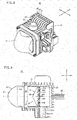
- FIG. 2 is a vertical sectional view (a vertical sectional view in the front-rear direction of the motorcycle 1) including the center line X of the outer lens 21 of the light module 20 of a region near the headlight 10 in FIG. 1 .
- the headlight 10 includes a housing 11 and an outer cover 12.
- the housing 11 supports the light module 20.
- the housing 11 may directly support the light module 20 or may indirectly support the light module 20 via another member.
- the housing 11 includes an opening in the front.
- the outer cover 12 is attached to the front surface of the housing 11 and covers the opening of the housing 11.
- a headlight chamber 13 is formed by the housing 11 and the outer cover 12.
- the light module 20 is located in the headlight chamber 13.
- FIG. 3 is a perspective view of the light module 20 in FIG. 2 .
- the light module 20 includes the outer lens 21 and a housing 22.
- the housing 22 is a housing including an opening in the front.
- the housing 22 includes a plurality of fins 23 for cooling on the outside.
- the outer lens 21 is attached to the front surface of the housing 22 and covers the opening of the housing 22.
- FIG. 4 is a horizontal sectional view of the light module 20 when viewed in a horizontal cross-section through the center of a plurality of light emitting diodes for low beam 24U.
- FIG. 5 is a vertical sectional view of the light module 20 when viewed in a vertical cross-section through a light emitting surface of the light emitting diode for low beam 24U.
- the outer lens 21 is attached to the front of the housing 22 to cover the opening.
- a housing chamber 28 is formed inside the light module 20 by the outer lens 21 and the housing 22.
- the light module 20 includes, in the housing chamber 28, the light emitting diodes for low beam 24U, a light emitting diode for high beam 24D, a heat sink 25, wires 26, a reflector for high beam 27, and an inner lens for low beam 30.
- the plurality of light emitting diodes for low beam 24U emits light for forming a low beam (a dipped-light headlamp).
- the plurality of light emitting diodes for low beam 24U is arrayed in the left-right direction (the horizontal direction) of the light module 20.
- the light emitting diodes for low beam 24U are located above the center line X of the outer lens 21 and emit light for low beam forward.
- the light emitting diode for high beam 24D forms a high beam (a headlight for traveling).
- the light emitting diode for high beam 24D is located below the center line X of the outer lens 21 and radiates the light downward.
- the light from the light emitting diode for high beam 24D is reflected on the reflector for high beam 27 and guided to above the center line X.
- the light emitting diode for high beam 24D is located below the light emitting diodes for low beam 24U.
- the heat sink 25 is located in a rear part of the housing 22.
- the rear surface of the heat sink 25 is in contact with the rear surface of the housing chamber 28.
- the upper surface of the heat sink 25 is in contact with the upper surface of the housing chamber 28.
- Both the side surfaces (the left side surface and the right side surface) of the heat sink 25 are respectively in contact with both the side surfaces (the left side surface and the right side surface) of the housing chamber 28.
- the light emitting diodes for low beam 24U and the light emitting diode for high beam 24D are attached to the heat sink 25 via a board. Specifically, the plurality of light emitting diodes for low beam 24U is attached to the front surface of the heat sink 25.
- the light emitting diode for high beam 24D is attached to the lower surface of the heat sink 25.
- the heat sink 25 removes heat emitted by the light emitting diodes for low beam 24U and the light emitting diode for high beam 24D and discharges the heat to the outside via the fins 23.
- the reflector for high beam 27 receives light from the light emitting diode for high beam 24D, reflects the light, and guides the light to the outer lens 21 as the light for high beam.
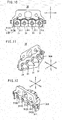
- FIG. 6 is a perspective view of a configuration around the reflector for high beam 27.
- the reflector for high beam 27 includes a ceiling plate 271 and a reflection bottom plate 272.
- the shape of the reflection bottom plate 272 when viewed in the vertical cross-section including the center line X is a quarter elliptical arcuate shape.
- the shape of the reflection bottom plate 272 when viewed in the vertical cross-section perpendicular to the center line X of the reflection bottom plate 272 is a half elliptical arcuate shape.
- the center portion of the reflection bottom plate 272 is located in the bottom and both the end portions of the reflection bottom plate 272 are located at the top.
- the ceiling plate 271 is located above a front part of the reflection bottom plate 272.
- the light emitting diode for high beam 24D is located above a rear part of the reflection bottom plate 272. A light emitting surface of the light emitting diode for high beam 24D is directed downward. The light emitting diode for high beam 24D emits the light downward.
- the inner lens for low beam 30 is located in front of the light emitting diodes for low beam 24U. At least a part of the inner lens for low beam 30 is located above the reflector for high beam 27. In FIG. 5 , the inner lens for low beam 30 is located on the ceiling plate 271. As shown in FIG. 5 , when viewed in a vertical cross-section through the center of the light emitting diode for low beam 24U, at least a part of the inner lens for low beam 30 is located above the center line X of the outer lens 21.
- the inner lens for low beam 30 receives light from light emitting surfaces of the light emitting diodes for low beam 24U, condenses and reflects the light, and emits the light for low beam toward the outer lens 21.
- the inner lens for low beam 30 includes a rear surface 31, an emission surface 32, and a light guide section 33.
- the rear surface 31 is located in front of the plurality of light emitting diodes for low beam 24U.
- the rear surface 31 receives the light emitted from the light emitting surfaces of the plurality of light emitting diodes for low beam 24U and collimates (condenses) or reflects a part of the light.
- the emission surface 32 receives the light from the rear surface 31 and emits the light to the outside as the light for low beam.
- the light guide section 33 is located between the rear surface 31 and the emission surface 32 and guides the light received and collimated or reflected by the rear surface 31 to the emission surface 32.
- the inner lens for low beam 30 is transparent.
- the material of the inner lens for low beam 30 (including the light guide section 33, the emission surface 32, and the rear surface 31) may be glass or may be resin.
- the material of the inner lens for low beam 30 is not limited to glass or resin and only has to be a material that is transparent.
- FIG. 7 is a perspective view of the inner lens for low beam 30 viewed obliquely from the upper left front.
- FIG. 8 is a left side view of the inner lens for low beam 30.
- FIG. 9 is a perspective view of the inner lens for low beam 30 viewed obliquely from the lower left front.
- FIG. 10 is a rear view of the inner lens for low beam 30.
- FIG. 11 is a perspective view of the inner lens for low beam 30 viewed obliquely from the lower right rear.
- FIG. 12 is a perspective view of the inner lens for low beam 30 viewed obliquely from the upper right rear.
- the rear surface 31 of the inner lens for low beam 30 includes a plurality of light-receiving surfaces 310 and a plurality of reflector surfaces 311.
- the emission surface 32 is equivalent to the front surface of the inner lens for low beam 30.
- the light guide section 33 is located between the emission surface 32 and the rear surface 31.
- an upper surface 34, a lower surface 35, a left side surface 36L, and a right side surface 36R are located in the light guide section 33.
- the upper surface 34 and the lower surface 35 are connected via the left and right side surfaces 36L and 36R.
- the upper surface 34, the lower surface 35, and the left and right side surfaces 36L and 36R form the circumferential surface of the inner lens for low beam 30.
- the circumferential surface is connected to the emission surface 32 and the rear surface 31.
- the plurality of light-receiving surfaces 310 is arrayed in the left-right direction of the light module 20 when viewed in the horizontal cross-section through the center of the light emitting diodes for low beam 24U (see FIG. 4 ).
- the light-receiving surfaces 310 are located in front of the light emitting diodes for low beam 24U in the front-rear direction of the light module 20.
- FIG. 13 is an enlarged view of the inner lens for low beam 30 in a portion near the light-receiving surface 310 when viewed in a horizontal cross-section through the light emitting surface of the light emitting diode for low beam 24U.
- the light-receiving surface 310 has a concave shape recessed forward.
- the light-receiving surface 310 includes a convex bottom surface section 310B and a circumferential surface section 310S.
- the convex bottom surface section 310B is located in front of the light emitting diode for low beam 24U.
- the convex bottom surface section 310B has a shape curved in a convex shape centrally projecting in a backward direction.
- the circumferential surface section 310S is cylindrical and is connected to a circumferential edge of the convex bottom surface section 310B at the front end. As shown in FIG. 13 , when viewed in the horizontal cross-section through the light emitting surface of the light emitting diode for low beam 24U, the width of the circumferential surface section 310S gradually decreases from the rear toward the front.
- the plurality of reflector surfaces 311 are arrayed in the left-right direction of the light module 20.
- the light-receiving surface 310 is located in the center of each of the reflector surfaces 311.
- the reflector surfaces 311 have a tapered shape, the width of which gradually decreases from the front toward the rear of the light module 20.
- each of the reflector surfaces 311 includes a left reflector surface section 311L and a right reflector surface section 311R.
- the left reflector surface section 311L is located on the left of the light-receiving surface 310.
- the left reflector surface section 311L reflects light received by (the circumferential surface section 310S of) the light-receiving surface 310 and guides the light to the emission surface 32.
- the right reflector surface section 311R is located on the right of the light-receiving surface 310.
- the right reflector surface section 311R reflects the light received by (the circumferential surface section 310S of) the light-receiving surface 310 and guides the light to the emission surface 32.
- the rear ends of the left reflector surface section 311L and the right reflector surface section 311R are connected to the rear end of the light-receiving surface 310. Further, the reflector surfaces 311 adjacent to each other are connected at the front end edges.
- the light-receiving surface 310 receives, in the convex bottom surface section 310B and the circumferential surface section 310S, light from the light emitting surface of the light emitting diode for low beam 24U.
- the convex bottom surface section 310B has the convex shape projecting in a backward direction. Therefore, the convex bottom surface section 310B collimates (condenses) the received light.
- the light-receiving surface 310 has a collimating function for collimating a part of the received light and guiding the light forward. The collimated light travels forward in the light guide section 33.
- the circumferential surface section 310S in the light-receiving surface 310 refracts the received light and guides the light to the reflector surface 311.
- the reflector surface 311 receives the light received by the circumferential surface section 310S, reflects the lights and guides the light forward.
- the reflector surface 311 reflects the received light and guides the light forward as collimated light.
- the reflector surface 311 has a reflecting function for reflecting light to thereby guide the light forward.
- the inner lens for low beam 30 guides the light from the light emitting diode for low beam 24U forward as the light for low beam using two light distribution adjusting functions, that is, the collimating function by the convex bottom surface section of the light-receiving surface 310 and the reflecting function by the reflector surface 311. Consequently, it is possible to adjust the spread in the vehicle left-right direction of the low beam and secure illuminance. Further, by adopting the inner lens for low beam 30, the size of the light module can be reduced compared to when a reflector for low beam is adopted.
- the emission surface 32 is equivalent to the front surface of the inner lens for low beam 30 and is located in front of the light-receiving surface 310 and the reflector surface 311.
- FIG. 14 is an enlarged view of the inner lens for low beam 30 in FIG. 4 .
- the emission surface 32 includes a left emission surface section 32L and a right emission surface section 32R.
- the left emission surface section 32L is located on the left side of the center line X of the outer lens 21.
- the right emission surface section 32R is located on the right side of the center line X.
- the left emission surface section 32L refracts light received from (the convex bottom surface sections 310B of) the light-receiving surfaces 310 and the reflector surfaces 311 rightward and emits the light forward.
- the right emission surface section 32R refracts light received from (the convex bottom surface sections 310B of) the light-receiving surfaces 310 and the reflector surfaces 311 leftward and emits the light forward.
- the emission surface 32 provides diffused light to the light-receiving surface of the outer lens 21.
- a radiation angle of the diffused light reaching the outer lens 21 is smaller than a radiation angle of the diffused light on the light emitting surfaces of the light emitting diodes for low beam 24U.
- the inner lens for low beam 30 adjusts the radiation angle of the diffused light from the light emitting diodes for low beam 24U and narrows the radiation angle to a radiation angle suitable for the light for low beam.
- the emission surface 32 when viewed in the horizontal cross-section through the center of the light emitting diodes for low beam 24U, the emission surface 32 has a ridge shape (a tapered shape) having a peak 32T as a top.
- the left emission surface section 32L and the right emission surface section 32R are located symmetrically with respect to the center line X of the outer lens 21.
- the outer lens 21 when viewed in the horizontal cross-section through the light emitting surfaces of the light emitting diodes for low beam 24U, the outer lens 21 includes an emission surface 211 curved forward in a convex shape.
- the emission surface 211 receives diffused light from the inner lens for low beam 30 and emits the diffused light forward as the light for low beam.
- the emission surface 211 of the outer lens 21 is convex as explained above.
- a radiation angle of the light for low beam (the diffused light) emitted from the emission surface 211 is adjusted to be slightly narrower than a radiation angle of the diffused light received by the outer lens 21 from the inner lens for low beam 30.
- the outer lens 21 is transparent.
- the material of the outer lens 21 may be glass or may be resin.
- the material of the outer lens 21 is not limited to glass or resin and only has to be a material that is transparent.
- the light module 20 can secure the spread and the illuminance in the left-right direction of the low beam when viewed in the horizontal cross-section through the center of the light emitting diodes for low beam 24U.
- FIG. 15 is a schematic diagram of an optical path of the light module 20 when viewed in the horizontal cross-section through the light emitting surfaces of the light emitting diodes for low beam 24U.
- FIG. 16 is an enlarged view of a portion near the inner lens for low beam 30 in FIG. 15 .
- light emitted from the light emitting diodes for low beam 24U is diffused light.
- a radiation angle of the diffused light at the time when the diffused light is emitted from the light emitting surfaces of the light emitting diodes for low beam 24U is a wide angle and is, for example, approximately 120°. However, the radiation angle of the diffused light is not limited to approximately 120°.
- the light emitted from the light emitting diodes for low beam 24U is made incident on the light-receiving surfaces 310.
- the convex bottom surface sections 310B have a shape curved convex backward. Therefore, the convex bottom surface sections 310B collimate (condense) the received light and guide the light forward (the collimating function). In other words, most of the light emitted by the light emitting diodes for low beam 24U is collimated by the convex bottom surface sections 310B and travel forward.
- light not made incident on the convex bottom surface sections 310B among light L1 received by the light-receiving surfaces 310 is made incident on the circumferential surface sections 310S.
- Most of the light made incident on the circumferential surface sections 310S is refracted by the circumferential surface sections 310S and thereafter made incident on the reflector surfaces 311 (the left reflector surface sections 311L or the right reflector surface sections 311R).
- the left reflector surface sections 311L and the right reflector surface sections 311R totally reflect the received light L1 and guide the light L1 forward as substantially collimated light (the reflecting function).
- the inner lens for low beam 30 guides most of the light emitted from the light emitting diodes for low beam 24U forward. Therefore, it is possible to sufficiently secure the illuminance of the low beam in the left-right direction. Further, the light emitted from the inner lens for low beam 30 is diffused and emitted to the outside as the low beam having the spread left and right by the outer lens 21 including the emission surface 211 curved in the convex shape.
- the emission surface 32 includes the left emission surface section 32L and the right emission surface section 32R, further, as shown in FIGS. 15 and 16 , the collimated lights traveling in the light guide section 33 forward from the light-receiving surfaces 310 and the reflector surfaces 311 is made incident on the left emission surface section 32L and the right emission surface section 32R.
- the left emission surface section 32L refracts and emits the received light rightward.
- the right emission surface section 32R refracts and emits the received light leftward.
- the outer lens 21 receives diffused light.
- a radiation angle of the diffused light at this point is adjusted to be narrower than the radiation angle of the diffused light on the light emitting surfaces of the light emitting diodes for low beam 24U.
- the light emitted from the inner lens for low beam 30 change to the diffused light when the light is made incident on the outer lens 21 (on the light-receiving surface of the outer lens 21).
- the radiation angle of the diffused light is a radiation angle narrower than the radiation angle of the diffused light of the light emitting diodes for low beam 24U and suitable for the light for low beam.
- the inner lens for low beam 30 delivers the diffused light, the radiation angle of which is adjusted to be narrower than the diffused light on the light emitting surfaces of the light emitting diodes for low beam 24U, to the outer lens 21.
- the outer lens 21 refracts the received diffused light in the center line X direction and emits the diffused light to the outside from the emission surface 211. In other words, the outer lens 21 further narrows the radiation angle of the received diffused light and emits the diffused light at the radiation angle suitable for the light for low beam.
- the diffused light from the light emitting diodes for low beam 24U are changed to the substantially collimated light.
- the substantially collimated light travels forward in the light guide section 33 and reaches the emission surface 32.
- the emission surface 32 emits the received light forward.
- the emission surface 32 delivers the diffused light, the radiation angle of which is adjusted to be narrower than the radiation angle of the diffused light on the light emitting surfaces of the light emitting diodes for low beam 24U, to the outer lens 21.
- the outer lens 21 receives the diffused light from the inner lens for low beam 30 and emits the diffused light, the radiation angle of which is slightly narrowed, forward as the light for low beam.
- the diffused light of the light emitting diodes for low beam 24U is changed once to the substantially collimated light on the light-receiving surfaces 310 of the inner lens for low beam 30.
- the diffused light is formed on the emission surface 32. Consequently, it is possible to adjust the radiation angle of the diffused light from the light emitting diodes for low beam 24U.
- the radiation angle of the diffused light from the inner lens for low beam 30 is further adjusted using the convex outer lens 21 to the radiation angle suitable for the light for low beam.
- the illuminance in the center region in the light distribution region of the low beam can be higher than the illuminance of the peripheral region of the center region. It is possible to intentionally form a variation of the illuminance (illuminance unevenness).
- the size of the light module 20 can be reduced more than in the projector-type light module in the past.
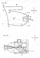
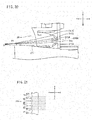
- FIG. 17 is a comparative diagram of the light module 20 and a projector-type light module 300 when viewed in the vertical cross-section through the light emitting surface of the light emitting diode for low beam 24U.
- a low beam is diffused and emitted to a wider range when viewed in the horizontal cross-section and the vertical cross-section than a high beam.
- a range of a light distribution region in the left-right direction of the low beam is wider than the range of the high beam.
- light emitted from an outer lens is further diffused and the light distribution region further expands as the focus of a reflector is located further backward in a light module.
- the focus of a reflector for low beam 303 is located behind the focus of a reflector for high beam 304.
- the rear end of the reflector for low beam 303 is located behind the rear end of the reflector for high beam 304. Since the reflector for low beam 303 is shifted to behind the reflector for high beam 304, the projector-type light module 300 is long in the front-rear direction.
- the inner lens for low beam 30 is used instead of the reflector for low beam 303. If the inner lens for low beam 30 is used, even if the light emitting diode for low beam 24U is located in front of the light emitting diode for high beam 24D, the light module 20 can form the low beam sufficiently wide in the left-right direction and having high illuminance.
- the length of the inner lens for low beam 30 including the functions explained above can be reduced in the front-rear direction compared with the reflector for low beam 303. Therefore, as shown in FIG. 17 , the front-rear length of the light module 20 can be reduced compared with the front-rear length of the light module 300 including the pair of reflectors 303 and 304. As a result, the size of the light module 20 can be reduced.
- the size of the light module including the inner lens for low beam 30 can be reduced more than in the light module including the reflector for low beam 303. This is because, as explained above, the length of the inner lens for low beam 30 can be reduced in the front-rear direction compared with the reflector for low beam 303.
- the light module 20 when viewed in the horizontal cross-section through the light emitting surfaces of the light emitting diodes for low beam 24U, it is possible to realize the low beam having the spread in the left-right direction and having high illuminance with the condensing function of the light-receiving surfaces 310 and the reflecting function of the reflector surfaces 311.
- the shape of the light module 20 is suitable as explained below.
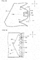
- FIG. 18 is a sectional view of a portion near the inner lens for low beam 30 when viewed in the vertical cross-section through the light emitting surface of the light emitting diode for low beam 24U.
- the convex bottom surface section 310B when viewed in the vertical cross-section, also has a convex shape curved convex backward.
- the circumferential surface section 310S is cylindrical. The width of the circumferential surface section 310S gradually decreases from the rear toward the front.
- the reflector surface 311 includes an upper reflector surface section 311U and a lower reflector surface section 311D.
- the upper reflector surface section 311U is located above the light-receiving surface 310.
- the upper reflector surface section 311U reflects light from (the circumferential surface 310S of) the light-receiving surface 310 and guides the light forward.
- the lower reflector surface section 311D is located below the light-receiving surface 310.
- the lower reflector surface section 311D reflects light from (the circumferential surface section 310S of) the light-receiving surface 310 and guides the light forward.
- the rear ends of the upper reflector surface section 311U and the lower reflector surface section 311 D are connected to the rear end of the light-receiving surface 310.
- a center 310C of the convex bottom surface section 310B is offset from the center line X of the outer lens 21.
- the inner lens for low beam 30 By locating the inner lens for low beam 30 to deviate from the center line X, a space can be secured in a peripheral region of the center line X. Therefore, it is possible to provide, in the space, other functions (in this example, installation of the reflector for high beam 27) other than the inner lens for low beam 30. Therefore, flexibility of design flexibility of the light module increases.
- the center 310C of the convex bottom surface section 310B is desirably located above the center line X.
- a normal 310N through the center 310C of the convex bottom surface section 310B desirably tilts with respect to the center line X of the outer lens 21.
- a point 310F located in front of the convex bottom surface section 310B in the normal 310N is more desirably located below a point 310B located behind the convex bottom surface section 310B.
- the normal 310N tilts downward toward the front.
- light condensed by the convex bottom surface section 310B travels obliquely downward toward the front. Therefore, it is possible to easily form the light for low beam when viewed in the vertical cross-section.
- the shape of the light-receiving surface 310 when viewed in the horizontal cross-section through the light emitting surface of the light emitting diode for low beam 24U (see FIG. 13 ), the shape of the light-receiving surface 310 is symmetrical with respect to the normal 310N through the center of the convex bottom surface section 310B.
- the shape of the light-receiving surface 310 when viewed in the vertical cross-section through the light emitting surface of the light emitting diode for low beam 24U (see FIG. 18 ), the shape of the light-receiving surface 310 is asymmetrical with respect to the normal 310N through the center of the convex bottom surface section 310B.
- the inner lens for low beam 30 by making the shape of the light-receiving surface 310 symmetrical when viewed in the horizontal cross-section and asymmetrical when viewed in the vertical cross-section, it is possible to form a light distribution region (i.e., a low beam) located below the center line X of the outer lens 21 in the up-down direction while forming a uniform light distribution region in the left-right direction.
- a light distribution region i.e., a low beam
- one of a front end P 311U of the upper reflector surface section 311U and a front end P 311D of the lower reflector surface section 311D is located in front of the other.
- the front end P 311U is located in front of the front end P 311D .
- an amount of light reflected by the upper reflector surface section 311U is larger than an amount of light reflected by the lower reflector surface section 311D. Therefore, it is easier to increase the illuminance of the low beam.
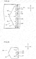
- FIG. 19 is a schematic diagram of an optical path of the light module 20 when viewed in the vertical cross-section through the light emitting surface of the light emitting diode for low beam 24U.
- FIG. 20 is an enlarged view of a portion near the inner lens for low beam 30 in FIG. 19 .
- the convex bottom surface section 310B has a shape curved convex backward. Therefore, the convex bottom surface section 310B collimates (condenses) the received light and guides the light forward.
- the normal 310N of the convex bottom surface section 310B tilts with respect to the center line X. More specifically, the normal 310N tilts obliquely downward towards the front.
- the light condensed by the convex bottom surface section 310B does not travel in parallel to the center line X and travel obliquely downward towards the front with respect to the center line X.
- the light is emitted from the emission surface 32 and thereafter condensed near a focus F1 in the housing chamber 28. Thereafter, the light is made incident on the rear surface 210 of the outer lens 21 as diffused light.
- the outer lens 21 refracts the light slightly upward on the emission surface 211 and emits the light to the outside as the light for low beam.
- a part of the emitted light (the diffused light) of the light emitting diode for low beam 24U is made incident on the circumferential surface section 310S without being made incident on the convex bottom surface section 310B in the light-receiving surface 310.
- the light is refracted by the circumferential surface section 310S and thereafter reach the upper reflector surface section 311U and the lower reflector surface section 311D.
- the upper reflector surface section 311U and the lower reflector surface section 311D reflect the light and guide the light forward. At this point, most of the light reflected by the upper reflector surface section 311U and the lower reflector surface section 311D is inclined with respect to the center line X.
- the light travels obliquely downward toward the front with respect to the center line X.
- the light is also emitted from the emission surface 32 and thereafter condensed near the focus F1. Thereafter, the light is made incident on the rear surface 210 of the outer lens 21 as diffused light.
- the outer lens 21 refracts the light slightly upward on the emission surface 211 and emits the light to the outside as the light for low beam.
- the light module 20 including the inner lens for low beam 30 and the outer lens 21 can form the low beam.
- the light module 20 of the present invention includes the light emitting diode for high beam 24D and the reflector for high beam 27, an optical path of light emitted from the light emitting diode for high beam 24D is as explained below.
- the light emitting diode for high beam 24D emits light downward.
- the light emitted from the light emitting diode for high beam 24D is diffused light.
- Most of the diffused light is reflected on the reflection bottom plate 272 of the reflector for high beam 27 and travel obliquely front upward.
- Most of the reflected light is condensed near a focus F2 located in front of the focus F1.
- the light travels as the diffused light and is refracted in the center line X direction on the rear surface 210 of the outer lens 21.
- the light after the refraction travels in the outer lens 21 and is refracted in a direction away from the center line X on the emission surface 211 and emitted to the outside as the high beam.
- the focus F2 is located in front of the focus F1. Therefore, the spread in the up-down direction of the high beam is narrower than the spread in the up-down direction of the low beam. As explained above, the light module 20 emits the high beam and the low beam.
- the emission surface 32 of the inner lens for low beam 30 may include a plurality of convex sections 321 arrayed in the left-right direction.
- FIG. 21 is a horizontal sectional view of the vicinity of the emission surface 32.
- a horizontal sectional shape of the convex sections 321 serving as an example is a bow shape.
- the convex sections 321 may be semispherical lenses or semi-ellipsoidal lenses or may be cylindrical lenses extending in the vertical direction.
- the shapes of the convex sections 321 may be different from one another.
- the emission surface 32 may include the plurality of convex sections 321 having the same shape.
- the plurality of convex sections 321 further diffuses incident light. Therefore, it is possible to blur the contour of the light distribution region of the low beam in the left-right direction.
- the convex sections 321 preferably extend in the vertical direction. In this case, it is possible to blur the contour of the light distribution region in the left-right direction of the low beam and clarify the contour in the up-down direction.
- the emission surface 32 may be flat without including the convex sections 321. In this case, the contour of the light distribution region of the low beam is clear.
- the light module 20 includes the plurality of light emitting diodes for low beam 24U and the inner lens for low beam 30 includes the plurality of light-receiving surfaces 310 and the plurality of reflector surfaces 311.
- the inner lens for low beam 30 includes the plurality of light-receiving surfaces 310 and the plurality of reflector surfaces 311.
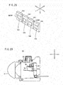
- FIG. 23 is a sectional view of the vicinity of the inner lens for low beam 30 of the light module 20 when viewed in the horizontal plane through the center of the light emitting diode for low beam 24U.
- one light-receiving surface 310 and one reflector surface 311 are provided in the inner lens for low beam 30.
- the number of the light emitting diodes for low beam 24U provided in the light module 20 is not particularly limited. As shown in FIG. 24 , two light emitting diodes for low beam 24U may be located side by side in the left-right direction. In this case, two light-receiving surfaces 310 are also located side by side in the left-right direction and two reflector surfaces 311 are also located side by side in the left-right direction.
- three light emitting diodes for low beam 24U may be located side by side in the left-right direction.
- three light-receiving surfaces 310 are also located side by side in the left-right direction and three reflector surfaces 311 are also located side by side in the left-right direction.
- FIG. 26 is a perspective view of the light emitting diode for low beam 24U shown in FIG. 23 .
- width 240HW in the left-right direction of the light module 20 of a light emitting surface 240 of the light emitting diode for low beam 24U is larger than width 240VW in the up-down direction of the light module 20.
- the width in the left-right direction of the light module 20 is larger than the width in the up-down direction of the light module 20. It is possible to form the light distribution region more appropriate for the low beam.
- FIG. 26 desirably, width 240HW in the left-right direction of the light module 20 of a light emitting surface 240 of the light emitting diode for low beam 24U is larger than width 240VW in the up-down direction of the light module 20.
- the width in the left-right direction of the light module 20 is larger than the width in the up-down direction of the light module 20. It is possible to form the light distribution region more appropriate for the low beam.
- the width 240HW may be equal to the width 240VW (i.e., the light emitting surface 240 may be a square) or may be smaller than the width 240VW. Note that the light emitting surface 240 is not limited to a rectangle.
- the light emitting surface 240 may be a circle or an ellipse or may be a polygon (a triangle, a pentagon, etc.).
- the light emitting diode for low beam 24U may include a plurality of light emitting surfaces 240 arrayed in the left-right direction of the light module 20 on a board.
- the width 240HW in the left-right direction of the light module 20 of the light emitting surface 240 is defined by the distance between the left-most end of the light emitting surface 240 located at the left-most end and the right-most end of the light emitting surface 240 located at the right-most end among the plurality of light emitting surfaces 240 arrayed on the left and the right.
- the width 240VW in the up-down direction of the light module 20 of the light emitting surface 240 is defined by the distance between the uppermost end and the lowermost end of the plurality of light emitting surfaces 240 arrayed in the left-right direction.
- FIG. 28 is a perspective view of the plurality of light emitting diodes for low beam 24U arrayed in the left-right direction of the light module 20 in the light module 20 shown in FIG. 4 .
- the definitions of the width 240HW and the width 240VW are the same as the definitions in FIG. 27 .
- At least one of the plurality of light emitting diodes for low beam 24U is located on the left side of the center line X of the outer lens 21 and at least one of the plurality of light emitting diodes for low beam 24U is located on the right side of the center line X of the outer lens 21.
- At least one of the plurality of light-receiving surfaces 310 is located on the left side of the center line X of the outer lens 21 and at least one of the plurality of light-receiving surfaces 310 is located on the right side of the center line X of the outer lens 21.
- at least one of the plurality of reflector surfaces 311 is located on the left side of the center line X of the outer lens 21 and at least one of the plurality of reflector surfaces 311 is located on the right side of the center line X of the outer lens 21.
- the illuminance of the light distribution region of the low beam on the left side of the center line X of the outer lens 21 can be matched to the illuminance of the light distribution region of the low beam on the right side of the center line X of the outer lens 21 to a certain degree.
- the number of the light emitting diodes for low beam 24U located on the left side of the center line X of the outer lens 21 is desirably equal to the number of the light emitting diodes for low beam 24U located on the right side of the center line X of the outer lens 21.
- the number of the light-receiving surfaces 310 located on the left side of the center line X of the outer lens 21 is equal to the number of the light-receiving surfaces 310 located on the right side of the center line X of the outer lens 21.
- the number of the reflector surfaces 311 located on the left side of the center line X of the outer lens 21 is equal to the number of the reflector surfaces 311 located on the right side of the center line X of the outer lens 21.
- the illuminance of the light distribution region of the low beam on the left side of the center line X of the outer lens 21 can uniformly be matched to the illuminance of the light distribution region of the low beam on the right side of the center line X of the outer lens 21.
- the number of the light emitting diodes for low beam 24U located on the left side of the center line X of the outer lens 21 may be different from the number of the light emitting diodes for low beam 24U located on the right side of the center line X of the outer lens 21.
- the number of the light-receiving surfaces 310 located on the left side of the center line X of the outer lens 21 may be different from the number of the light-receiving surfaces 310 located on the right side of the center line X of the outer lens 21.
- the number of the reflector surfaces 311 located on the left side of the center line X of the outer lens 21 may be different from the number of the reflector surfaces 311 located on the right side of the center line X of the outer lens 21.
- the plurality of light emitting diodes for low beam 24U when viewed in the horizontal cross-section through the light emitting surfaces of the light emitting diodes for low beam 24U, the plurality of light emitting diodes for low beam 24U is desirably located in positions symmetrical with respect to the center line X of the outer lens 21.
- the plurality of light-receiving surfaces 310 is located in positions symmetrical with respect to the center line X of the outer lens 21.
- the plurality of reflector surfaces 311 is located in positions symmetrical with respect to the center line X of the outer lens 21.
- the illuminance of the light distribution region of the low beam on the left side of the center line X of the outer lens 21 can uniformly be matched to the illuminance of the light distribution region of the low beam on the right side of the center line X of the outer lens 21.
- the plurality of light emitting diodes for low beam 24U do not have to be located in positions symmetrical with respect to the center line X of the outer lens 21.
- the plurality of light-receiving surfaces 310 do not have to be located in positions symmetrical with respect to the center line X of the outer lens 21.
- the plurality of reflector surfaces 311 do not have to be located in positions symmetrical with respect to the center line X of the outer lens 21.
- one of a front end P 311L of the left reflector surface section 311L and a front end P 311R of the right reflector surface section 311R of the reflector surface 311 is desirably located in front of the other.
- the left reflector surface section 311 L and the right reflector surface section 311R have different lengths.
- the front end closer to the center line X of the outer lens 21 is located in front of the front end farther from the center line X.
- the light guide section 33 of the inner lens for low beam 30 decreases in thickness farther away from the center line X. It is possible to secure the strength of the inner lens for low beam 30 by adjusting the front end positions of the reflector surface sections according to the thickness.
- the light module 20 emits the low beam and the high beam. However, as shown in FIG. 29 , the light module 20 may emit the low beam and not emit the high beam. In this case, the light module 20 includes the light emitting diodes for low beam 24U and the inner lens for low beam 30 and does not include the light emitting diode for high beam 24D and the reflector for high beam 27.
- the ceiling plate 271 of the reflector for high beam 27 extends obliquely upward toward the front.
- a part of a lower part of the inner lens for low beam 30 and the ceiling plate 271 may overlap.
- light emitted from the vicinity of a lower end 32B of the emission surface 32 of the inner lens for low beam 30 is blocked by the ceiling plate 271. Consequently, when viewed in the vertical cross-section including the center of the light emitting diode for low beam 24U, light of the light emitting diode for low beam 24U is suppressed from being emitted, to above the center line X of the outer lens 21.
- the light module 20 includes one light emitting diode for high beam 24D.
- a plurality of light emitting diodes for high beam 24D may be located.
- the inner lens for low beam 30 integrally includes the light-receiving surfaces 310, the reflector surfaces 311, and the emission surface 32.
- the shape of the inner lens for low beam 30 is not limited to the embodiment.
- the inner lens for low beam 30 may include a rear member including the light-receiving surfaces 310 and the reflector surfaces 311 and a front member located in front of the rear member and including the emission surface 32.
- the light-receiving surfaces 310, the reflector surfaces 311, and the emission surface 32 do not have to be integrally molded.
- the headlight 10 is attached to the front cowl 5.
- a position to which the headlight 10 is attached is not limited to the front cowl 5.
- the headlight 10 may be attached to a bracket supported by a vehicle body frame or may be attached to another member.
- the reflector surface 311 has the tapered shape gradually decreasing in width from the front toward the rear.
- the shape of the reflector surface 311 is not limited to such a tapered shape.
- the shape of the reflector surface 311 is not particularly limited as long as the reflector surface 311 can reflect light from the light emitting diodes for low beam 24U and guide the light forward.
- the shape of the emission surface 32 is not limited to the ridge shape.
- the shape of the emission surface 32 may be a bow shape recessed backward or may be a shape having a plurality of steps.
- the shape of the emission surface 32 is not particularly limited as long as the emission surface 32 refracts and emits light received by the left emission surface section 32L rightward and refracts and emits light received by the right emission surface section 32R leftward.
- the left emission surface section 32L and the right emission surface section 32R do not have to be located symmetrically with respect to the center line X.
- the left emission surface section 32L and the right emission surface section 32R may be located asymmetrically with respect to the center line X.
- the light emitting diode for high beam 24D is located below the center line X and located below the light emitting diodes for low beam 24U.
- the disposition of the light emitting diode for high beam 24D is not limited to this.
- the shape and the disposition of the heat sink 25 are not particularly limited as long as the heat sink 25 can remove heat generated by the light emitting diodes for low beam 24U and the light emitting diode for high beam 24D and discharge the heat to the outside.
Landscapes
- Engineering & Computer Science (AREA)
- General Engineering & Computer Science (AREA)
- Physics & Mathematics (AREA)
- Microelectronics & Electronic Packaging (AREA)
- Optics & Photonics (AREA)
- Mechanical Engineering (AREA)
- Non-Portable Lighting Devices Or Systems Thereof (AREA)
Claims (18)
- Ein Lichtmodul (20) für einen Scheinwerfer (10) eines Fahrzeugs, wobei das Lichtmodul (20) umfasst:eine lichtemittierende Diode für Abblendlicht (24U), die eine lichtemittierende Oberfläche beinhaltet, um erstes Licht in eine vorwärts-Richtung zu emittieren;eine innere Linse für Abblendlicht (30), die eine hintere Oberfläche (31), die eine Oberfläche ist, die konfiguriert ist, das von der lichtemittierenden Diode für Abblendlicht (24U) emittierte erste Licht zu empfangen, eine erste Emissionsoberfläche (32) und einen Lichtführungsabschnitt (33) beinhaltet, der konfiguriert ist, das durch die hintere Oberfläche (31) empfangene erste Licht zu der ersten Emissionsoberfläche (32) zu führen, wobei, in einem horizontalen Querschnitt durch die lichtemittierende Oberfläche der lichtemittierenden Diode für Abblendlicht (24U) gesehen, die hintere Oberfläche (31) beinhaltet:eine konkave Lichtempfangsoberfläche (310), die vor der lichtemittierenden Diode für Abblendlicht (24U) in einer vorne-hinten-Richtung des Lichtmoduls (20) gelegen ist und einen Abschnitt einer konvexen Bodenfläche (310B), der in einer konvexen Gestalt ausgebildet ist, die zentral in einer rückwärts-Richtung vorspringt, und einen Umfangsflächenabschnitt (310S) beinhaltet, die Lichtempfangsoberfläche (310) ist zum Empfangen des ersten Lichts von der lichtemittierenden Diode für Abblendlicht (24U); undeine Reflektoroberfläche (311), die einen Abschnitt einer rechten Reflektoroberfläche (311R), der zu der Rechten der Lichtempfangsoberfläche in einer links-rechts-Richtung des Lichtmoduls gelegen ist, der Abschnitt der rechten Reflektoroberfläche (311R) ist zum Reflektieren des durch die Lichtempfangsoberfläche (310) empfangenen ersten Lichts, und einen Abschnitt einer linken Reflektoroberfläche (311L) beinhaltet, der zu der Linken der Lichtempfangsoberfläche (310) in der links-rechts-Richtung des Lichtmoduls (20) gelegen ist, der Abschnitt der linken Reflektoroberfläche (311L) ist zum Reflektieren des ersten Lichts, die erste Emissionsoberfläche (32) vor dem Abschnitt der konvexen Bodenfläche (310B), dem Abschnitt der linken Reflektoroberfläche (311L) und dem Abschnitt der rechten Reflektoroberfläche (311R) gelegen ist, die erste Emissionsoberfläche (32) ist zum Emittieren des durch die Lichtempfangsoberfläche (310) empfangenen ersten Lichts; undeine äußere Linse (21), die vor der inneren Linse für Abblendlicht (30) gelegen ist eine zweite Emissionsoberfläche (211) beinhaltet, die in einer konvexen Gestalt ausgebildet ist, die zweite Emissionsoberfläche (211) ist zum Empfangen des von der ersten Emissionsoberfläche (32) emittierten ersten Lichts und zum Emittieren des ersten Lichts für Abblendlicht,die innere Linse (30) weiterhin eine untere Oberfläche (35) beinhaltet, die in dem Lichtführungsabschnitt (33) gelegen ist, die untere Oberfläche (35) verbindet die erste Emissionsoberfläche (32) und die hintere Oberfläche (31), wobei,in einem horizontalen Querschnitt durch die lichtemittierende Oberfläche der lichtemittierenden Diode für Abblendlicht (24U) gesehen,die erste Emissionsoberfläche (32) beinhaltet:einen Abschnitt einer linken ersten Emissionsoberfläche (32L), der an der linken Seite der Mittellinie der äußeren Linse (21) in der links-rechts-Richtung des Lichtmoduls (20) gelegen ist, der Abschnitt der linken ersten Emissionsoberfläche (32L) ist zum Brechen nach rechts und Emittieren des von der Lichtempfangsoberfläche (310) und der Reflektoroberfläche (311) empfangenen ersten Lichts; undeinen Abschnitt einer rechten ersten Emissionsoberfläche (32R), der an der rechten Seite der Mittellinie der äußeren Linse (21) in der links-rechts-Richtung des Lichtmoduls (20) gelegen ist, der Abschnitt der rechten ersten Emissionsoberfläche (32R) ist zum Brechen nach links und Emittieren des von der Lichtempfangsoberfläche (310) und der Reflektoroberfläche (311) empfangenen ersten Lichts, dadurch gekennzeichnet, dass,in einem vertikalen Querschnitt durch die lichtemittierende Oberfläche der lichtemittierenden Diode für Abblendlicht (24U) gesehen, die erste Emissionsoberfläche (32) in einer konkaven Gestalt ausgebildet ist.
- Das Lichtmodul (20) für den Scheinwerfer (10) des Fahrzeugs nach Anspruch 1, wobei das Lichtmodul (20) eine einzige der lichtemittierenden Diode für Abblendlicht (24U) oder eine Vielzahl der lichtemittierenden Dioden für Abblendlicht (24U) beinhaltet, die in der links-rechts-Richtung des Lichtmoduls (20) angeordnet sind, und
eine Breite in der links-rechts-Richtung des Lichtmoduls (20) einer einzigen oder einer Vielzahl der lichtemittierenden Oberflächen der einzigen oder der Vielzahl von lichtemittierenden Dioden für Abblendlicht (24U) größer ist als eine Breite in einer oben-unten-Richtung des Lichtmoduls (20) der einzigen oder der Vielzahl der lichtemittierenden Oberflächen der einzigen oder der Vielzahl von lichtemittierenden Dioden für Abblendlicht (24U). - Das Lichtmodul (20) für den Scheinwerfer (10) des Fahrzeugs nach Anspruch 1 oder 2, wobei,
in einem horizontalen Querschnitt durch die lichtemittierende Oberfläche der lichtemittierenden Diode für Abblendlicht (24U) gesehen,
das Lichtmodul (20) eine Vielzahl der lichtemittierenden Dioden für Abblendlicht (24U) beinhaltet, die in der links-rechts-Richtung des Lichtmoduls (20) angeordnet sind,
die innere Linse für Abblendlicht (30) beinhaltet:eine Vielzahl der Lichtempfangsoberflächen (310), die in der links-rechts-Richtung des Lichtmoduls (20) angeordnet sind, wobei jede der Lichtempfangsoberflächen (310) vor der jeweiligen lichtemittierenden Diode für Abblendlicht (24U) gelegen ist; undeine Vielzahl der Reflektoroberflächen (311), die in der links-rechts-Richtung des Lichtmoduls (20) angeordnet sind, wobei jeder der Abschnitte der linken Reflektoroberfläche (311L) in der jeweiligen Reflektoroberfläche (311) zu der Linken der jeweiligen Lichtempfangsoberfläche (310) in der links-rechts-Richtung des Lichtmoduls (20) gelegen ist und jeder der Abschnitte der rechten Reflektoroberfläche (311R) in der jeweiligen Reflektoroberfläche (311) zu der Rechten der jeweiligen Lichtempfangsoberfläche (310) in der links-rechts-Richtung des Lichtmoduls (20) gelegen ist,wobei die erste Emissionsoberfläche (32) vor der Vielzahl von Lichtempfangsoberflächen (310) und der Vielzahl von Abschnitten der linken Reflektoroberfläche (311L) und der Vielzahl von Abschnitten der rechten Reflektoroberfläche (311R) in der vorne-hinten-Richtung des Lichtmoduls (20) gelegen ist und ist zum Emittieren des durch die Vielzahl von Lichtempfangsoberflächen (310) empfangenen ersten Lichts, undwobei die äußere Linse (21) zum Empfangen des von der ersten Emissionsoberfläche emittierten ersten Lichts und zum Emittieren des ersten Lichts von der zweiten Emissionsoberfläche (211), die in der konvexen Gestalt ausgebildet ist, ist. - Das Lichtmodul (20) für den Scheinwerfer (10) des Fahrzeugs nach Anspruch 3, wobei,
in einem horizontalen Querschnitt durch die lichtemittierende Oberfläche der lichtemittierenden Diode für Abblendlicht (24U) gesehen,
zumindest eine der Vielzahl von lichtemittierenden Dioden für Abblendlicht (24U) auf einer linken Seite einer Mittellinie der äußeren Linse (21) gelegen ist und zumindest eine der Vielzahl von lichtemittierenden Dioden für Abblendlicht (24U) auf einer rechten Seite der Mittellinie der äußeren Linse (21) in der links-rechts-Richtung des Lichtmoduls (20) gelegen ist,
zumindest eine der Vielzahl von Lichtempfangsoberflächen (310) auf der linken Seite der Mittellinie der äußeren Linse (21) gelegen ist und zumindest eine der Vielzahl von Lichtempfangsoberflächen (310) auf der rechten Seite der Mittellinie der äußeren Linse (21) in der links-rechts-Richtung des Lichtmoduls (20) gelegen ist, und
zumindest eine der Vielzahl von Reflektoroberflächen (311) auf der linken Seite der Mittellinie der äußeren Linse (21) gelegen ist und zumindest eine der Vielzahl von Reflektoroberflächen (311) auf der rechten Seite der Mittellinie der äußeren Linse (21) in der links-rechts-Richtung des Lichtmoduls (20) gelegen ist. - Das Lichtmodul (20) für den Scheinwerfer (10) des Fahrzeugs nach Anspruch 4, wobei in einem horizontalen Querschnitt durch die lichtemittierende Oberfläche der lichtemittierenden Diode für Abblendlicht (24U) gesehen,
eine Anzahl der lichtemittierenden Dioden für Abblendlicht (24U), die auf der linken Seite der Mittellinie der äußeren Linse (21) gelegen sind, gleich einer Anzahl der lichtemittierenden Dioden für Abblendlicht (24U), die auf der rechten Seite der Mittellinie der äußeren Linse (21) in der links-rechts-Richtung des Lichtmoduls (20) gelegen sind, ist,
eine Anzahl der Lichtempfangsoberflächen (310), die auf der linken Seite der Mittellinie der äußeren Linse (21) gelegen sind, gleich einer Anzahl der Lichtempfangsoberflächen (310), die auf der rechten Seite der Mittellinie der äußeren Linse (21) in der links-rechts-Richtung des Lichtmoduls (20) gelegen sind, ist, und
eine Anzahl der Reflektoroberflächen (311), die auf der linken Seite der Mittellinie der äußeren Linse (21) gelegen sind, gleich einer Anzahl der Reflektoroberflächen (311), die auf der rechten Seite der Mittellinie der äußeren Linse (21) in der links-rechts-Richtung des Lichtmoduls (20) gelegen sind, ist. - Das Lichtmodul (20) für den Scheinwerfer (10) des Fahrzeugs nach Anspruch 5, wobei in einem horizontalen Querschnitt durch die lichtemittierende Oberfläche der lichtemittierenden Diode für Abblendlicht (24U) gesehen,
die Vielzahl von lichtemittierenden Dioden für Abblendlicht (24U) in Positionen symmetrisch bezüglich der Mittellinie der äußeren Linse (21) in der links-rechts-Richtung des Lichtmoduls (20) gelegen ist,
die Vielzahl von Lichtempfangsoberflächen (310) in Positionen symmetrisch bezüglich der Mittellinie der äußeren Linse (21) in der links-rechts-Richtung des Lichtmoduls (20) gelegen ist, und
die Vielzahl von Reflektoroberflächen (311) in Positionen symmetrisch bezüglich der Mittellinie der äußeren Linse (21) in der links-rechts-Richtung des Lichtmoduls (20) gelegen ist. - Das Lichtmodul (20) für den Scheinwerfer (10) des Fahrzeugs nach irgendeinem von Ansprüchen 1 bis 6, wobei, in einem horizontalen Querschnitt durch die lichtemittierende Oberfläche der lichtemittierenden Diode für Abblendlicht (24U) gesehen, eines von einem vorderen Ende des Abschnitts der linken Reflektoroberfläche (311L) und einem vorderen Ende des Abschnitts der rechten Reflektoroberfläche (311R) der Reflektoroberfläche (311) vor dem anderen in der vorne-hinten-Richtung des Lichtmoduls (20) gelegen ist.
- Das Lichtmodul (20) für den Scheinwerfer (10) des Fahrzeugs nach irgendeinem von Ansprüchen 1 bis 7, wobei,
in einem horizontalen Querschnitt durch die lichtemittierende Oberfläche der lichtemittierenden Diode für Abblendlicht (24U) gesehen, eine Gestalt des Umfangsflächenabschnitts (310S) der Lichtempfangsoberfläche (310) symmetrisch bezüglich einer Normalen (310N) ist, die eine Mitte des Abschnitts der konvexen Bodenfläche (310B) passiert, und,
in einem vertikalen Querschnitt durch die lichtemittierende Oberfläche der lichtemittierenden Diode für Abblendlicht (24U) gesehen, die Gestalt des Umfangsflächenabschnitts (310S) der Lichtempfangsoberfläche (310) asymmetrisch bezüglich der Normalen (310N) ist, die die Mitte des Abschnitts der konvexen Bodenfläche (310B) passiert. - Das Lichtmodul (20) für den Scheinwerfer (10) des Fahrzeugs nach irgendeinem von Ansprüchen 1 bis 8, wobei,
in einem vertikalen Querschnitt durch die lichtemittierende Oberfläche der lichtemittierenden Diode für Abblendlicht (24U) gesehen, eine Mitte des Abschnitts der konvexen Bodenfläche (310B) der Lichtempfangsoberfläche (310) von der Mittellinie der äußeren Linse (21) versetzt ist. - Das Lichtmodul (20) für den Scheinwerfer (10) des Fahrzeugs nach irgendeinem von Ansprüchen 1 bis 9, wobei,
in einem vertikalen Querschnitt durch die lichtemittierende Oberfläche der lichtemittierenden Diode für Abblendlicht (24U) gesehen, eine Normale (310N) einer Mitte des Abschnitts der konvexen Bodenfläche (310B) der Lichtempfangsoberfläche (310) bezüglich der Mittellinie der äußeren Linse (21) geneigt ist und, in der vorne-hinten-Richtung des Lichtmoduls (20), ein Punkt vor dem Abschnitt der konvexen Bodenfläche (310B) in der Normalen (310N) unter einem Punkt hinter dem Abschnitt der konvexen Bodenfläche (310B) in der Normalen (310N) gelegen ist. - Das Lichtmodul (20) für den Scheinwerfer (10) des Fahrzeugs nach irgendeinem von Ansprüchen 1 bis 10, wobei,
in einem vertikalen Querschnitt durch die lichtemittierende Oberfläche der lichtemittierenden Diode für Abblendlicht (24U) gesehen,
die Reflektoroberfläche (311) beinhaltet:einen Abschnitt einer oberen Reflektoroberfläche (311U), der über dem Abschnitt der konvexen Bodenfläche (310B) in einer oben-unten-Richtung des Lichtmoduls (20) gelegen ist, der Abschnitt der oberen Reflektoroberfläche (311U) ist zum Reflektieren des durch die Lichtempfangsoberfläche (310) empfangenen ersten Lichts; undeinen Abschnitt einer unteren Reflektoroberfläche (311D), der unter dem Abschnitt der konvexen Bodenfläche (310B) in der oben-unten-Richtung des Lichtmoduls (20) gelegen ist, der Abschnitt der unteren Reflektoroberfläche (311D) ist zum Reflektieren des durch die Lichtempfangsoberfläche (310) empfangenen ersten Lichts, undein vorderes Ende des Abschnitts der oberen Reflektoroberfläche (311U) vor einem vorderen Ende des Abschnitts der unteren Reflektoroberfläche (311D) in der vorne-hinten-Richtung des Lichtmoduls (20) gelegen ist. - Das Lichtmodul (20) für den Scheinwerfer (10) des Fahrzeugs nach irgendeinem von Ansprüchen 1 bis 11, wobei, in einem horizontalen Querschnitt durch die lichtemittierende Oberfläche der lichtemittierenden Diode für Abblendlicht (24U) gesehen, der Abschnitt der linken ersten Emissionsoberfläche (32L) und der Abschnitt der rechten ersten Emissionsoberfläche (32R) symmetrisch bezüglich der Mittelachse der äußeren Linse (21) gelegen sind.
- Das Lichtmodul (20) für den Scheinwerfer (10) des Fahrzeugs nach irgendeinem von Ansprüchen 1 bis 12, wobei, in einem vertikalen Querschnitt durch die lichtemittierende Oberfläche der lichtemittierenden Diode für Abblendlicht (24U) gesehen, ein oberes Ende der ersten Emissionsoberfläche (32) vor einem unteren Ende der ersten Emissionsoberfläche (32) in der vorne-hinten-Richtung des Lichtmoduls (20) gelegen ist.
- Das Lichtmodul (20) für den Scheinwerfer (10) des Fahrzeugs nach irgendeinem von Ansprüchen 11 bis 13, wobei, in einem horizontalen Querschnitt durch die lichtemittierende Oberfläche der lichtemittierenden Diode für Abblendlicht (24U) gesehen, die erste Emissionsoberfläche (32) eine Vielzahl von konvexen Abschnitten (321), die in der links-rechts-Richtung des Lichtmoduls (20) angeordnet sind, beinhaltet.
- Das Lichtmodul (20) für den Scheinwerfer (10) des Fahrzeugs nach irgendeinem von Ansprüchen 1 bis 14, wobei,
in einem vertikalen Querschnitt durch die lichtemittierende Oberfläche der lichtemittierenden Diode für Abblendlicht (24U) gesehen,
das Lichtmodul (20) weiterhin umfasst:eine lichtemittierende Diode für Fernlicht (24D) zum Emittieren eines zweiten Lichts in eine vorwärts-Richtung; undeinen Reflektor (27) zum Empfangen des zweiten Lichts von der lichtemittierenden Diode für Fernlicht (24D) und zum Führen des zweiten Lichts über die Mittellinie der äußeren Linse (21) in einer oben-unten-Richtung des Lichtmoduls (20), unddie äußere Linse (21) ist zum Empfangen des durch den Reflektor (27) geführten zweiten Lichts und zum Emittieren des zweiten Lichts als Licht für Fernlicht. - Das Lichtmodul (20) für den Scheinwerfer (10) des Fahrzeugs nach Anspruch 15, wobei, in einem vertikalen Querschnitt durch die lichtemittierende Oberfläche der lichtemittierenden Diode für Abblendlicht (24U) gesehen, die lichtemittierende Diode für Fernlicht (24D) hinter der lichtemittierenden Diode für Fernlicht (24U) in der vorne-hinten-Richtung des Lichtmoduls (20) gelegen ist.
- Ein Scheinwerfer (10) für ein Fahrzeug, umfassend das Lichtmodul (20) nach irgendeinem von Ansprüchen 1 bis 16.
- Ein Fahrzeug (1), umfassend den Scheinwerfer (10) nach Anspruch 17.
Applications Claiming Priority (1)
| Application Number | Priority Date | Filing Date | Title |
|---|---|---|---|
| IN201721002908 | 2017-01-25 |
Publications (2)
| Publication Number | Publication Date |
|---|---|
| EP3354545A1 EP3354545A1 (de) | 2018-08-01 |
| EP3354545B1 true EP3354545B1 (de) | 2020-03-18 |
Family
ID=61024652
Family Applications (1)
| Application Number | Title | Priority Date | Filing Date |
|---|---|---|---|
| EP18153195.5A Active EP3354545B1 (de) | 2017-01-25 | 2018-01-24 | Lichtmodul für fahrzeugscheinwerfer |
Country Status (2)
| Country | Link |
|---|---|
| EP (1) | EP3354545B1 (de) |
| TW (1) | TWI660867B (de) |
Families Citing this family (4)
| Publication number | Priority date | Publication date | Assignee | Title |
|---|---|---|---|---|
| AT519125B1 (de) * | 2017-01-20 | 2018-04-15 | Zkw Group Gmbh | Leuchtvorrichtung für einen Kraftfahrzeugscheinwerfer sowie Kraftfahrzeugscheinwerfer |
| US12188439B2 (en) | 2021-04-15 | 2025-01-07 | Bombardier Recreational Products Inc. | Snowmobile |
| JP7847497B2 (ja) * | 2022-07-13 | 2026-04-17 | スタンレー電気株式会社 | 車両用灯具 |
| DE102022209714B4 (de) * | 2022-09-15 | 2024-07-18 | Continental Automotive Technologies GmbH | Beleuchtungsvorrichtung und Display |
Family Cites Families (11)
| Publication number | Priority date | Publication date | Assignee | Title |
|---|---|---|---|---|
| JP4987069B2 (ja) * | 2006-05-02 | 2012-07-25 | コーニンクレッカ フィリップス エレクトロニクス エヌ ヴィ | 車両用ヘッドライト |
| TWI340808B (en) * | 2008-09-30 | 2011-04-21 | Univ Kao Yuan | Led headlight for vehicle |
| DE102010023177A1 (de) * | 2010-06-09 | 2011-12-15 | Automotive Lighting Reutlingen Gmbh | Lichtmodul für eine Beleuchtungseinrichtung eines Kraftfahrzeugs |
| DE102011112285A1 (de) * | 2011-09-05 | 2013-03-07 | Schott Ag | Lichtformung mittels LED-Lichtquelle |
| US8733992B2 (en) * | 2012-10-01 | 2014-05-27 | Osram Sylvania, Inc. | LED low profile linear front fog module |
| JP6180772B2 (ja) | 2013-04-01 | 2017-08-16 | 株式会社小糸製作所 | 車両用灯具 |
| DE202013101509U1 (de) * | 2013-04-09 | 2013-04-23 | Fu An Industrial Co., Ltd. | Optische Linse für Streifenbeleuchtungen |
| JP5968557B2 (ja) * | 2013-11-19 | 2016-08-10 | 三菱電機株式会社 | 前照灯モジュール及び前照灯装置 |
| KR102099792B1 (ko) * | 2013-12-11 | 2020-04-10 | 에스엘 주식회사 | 차량용 헤드 램프 |
| JP5889499B2 (ja) * | 2014-01-17 | 2016-03-22 | 三菱電機株式会社 | 車載用前照灯 |
| JP6376450B2 (ja) * | 2014-08-01 | 2018-08-22 | スタンレー電気株式会社 | レンズ体及び車両用灯具 |
-
2017
- 2017-12-28 TW TW106146159A patent/TWI660867B/zh active
-
2018
- 2018-01-24 EP EP18153195.5A patent/EP3354545B1/de active Active
Non-Patent Citations (1)
| Title |
|---|
| None * |
Also Published As
| Publication number | Publication date |
|---|---|
| EP3354545A1 (de) | 2018-08-01 |
| TWI660867B (zh) | 2019-06-01 |
| TW201827268A (zh) | 2018-08-01 |
Similar Documents
| Publication | Publication Date | Title |
|---|---|---|
| EP3354545B1 (de) | Lichtmodul für fahrzeugscheinwerfer | |
| US8936383B2 (en) | Saddle-riding type vehicle and light guide used in same | |
| EP2767750B1 (de) | Fahrzeugscheinwerfer | |
| US20140036526A1 (en) | Vehicle lighting unit | |
| EP2541131A2 (de) | Fahrzeugbeleuchtungseinheit | |
| CN109312903B (zh) | 车辆用前照灯以及使用其的车辆 | |
| JP7143716B2 (ja) | 車両用導光体および車両用灯具 | |
| US20190011103A1 (en) | Headlight module | |
| CN114688494A (zh) | 车辆用灯具 | |
| CN114060765A (zh) | 车辆用灯具 | |
| EP3000656B1 (de) | Scheinwerferstruktur für kraftfahrzeuge | |
| JP6030864B2 (ja) | 灯具ユニットおよび投影レンズ | |
| JP7171413B2 (ja) | 車両用灯具 | |
| KR102741968B1 (ko) | 자동차용 램프 | |
| JP6121629B2 (ja) | 車両のヘッドライト用ライトモジュール、車両のヘッドライト、および車両 | |
| KR102347922B1 (ko) | 조명용 광학렌즈 및 이를 이용한 조명장치 | |
| JP7826631B2 (ja) | 車両用前照灯モジュール、及び車両用前照灯ユニット | |
| JP2023148583A (ja) | 車両用灯具 | |
| KR102797332B1 (ko) | 램프 모듈 및 이를 포함하는 차량용 램프 | |
| JP6944966B2 (ja) | 灯火器 | |
| TWI815478B (zh) | 燈單元及傾斜車輛 | |
| KR102883488B1 (ko) | 차량용 램프 | |
| JP2007317596A (ja) | 車両用灯具ユニット | |
| JP2024085545A (ja) | ヘッドランプ | |
| KR20240054677A (ko) | 차량용 램프 및 이를 포함하는 차량 |
Legal Events
| Date | Code | Title | Description |
|---|---|---|---|
| PUAI | Public reference made under article 153(3) epc to a published international application that has entered the european phase |
Free format text: ORIGINAL CODE: 0009012 |
|
| STAA | Information on the status of an ep patent application or granted ep patent |
Free format text: STATUS: REQUEST FOR EXAMINATION WAS MADE |
|
| 17P | Request for examination filed |
Effective date: 20180124 |
|
| AK | Designated contracting states |
Kind code of ref document: A1 Designated state(s): AL AT BE BG CH CY CZ DE DK EE ES FI FR GB GR HR HU IE IS IT LI LT LU LV MC MK MT NL NO PL PT RO RS SE SI SK SM TR |
|
| AX | Request for extension of the european patent |
Extension state: BA ME |
|
| RBV | Designated contracting states (corrected) |
Designated state(s): AL AT BE BG CH CY CZ DE DK EE ES FI FR GB GR HR HU IE IS IT LI LT LU LV MC MK MT NL NO PL PT RO RS SE SI SK SM TR |
|
| STAA | Information on the status of an ep patent application or granted ep patent |
Free format text: STATUS: EXAMINATION IS IN PROGRESS |
|
| 17Q | First examination report despatched |
Effective date: 20190507 |
|
| GRAP | Despatch of communication of intention to grant a patent |
Free format text: ORIGINAL CODE: EPIDOSNIGR1 |
|
| STAA | Information on the status of an ep patent application or granted ep patent |
Free format text: STATUS: GRANT OF PATENT IS INTENDED |
|
| RIC1 | Information provided on ipc code assigned before grant |
Ipc: F21S 41/265 20180101ALI20191028BHEP Ipc: F21S 41/24 20180101ALI20191028BHEP Ipc: F21S 41/155 20180101ALI20191028BHEP Ipc: F21S 41/29 20180101ALI20191028BHEP Ipc: F21S 41/663 20180101ALI20191028BHEP Ipc: F21S 41/143 20180101ALI20191028BHEP Ipc: F21S 41/275 20180101ALI20191028BHEP Ipc: F21S 41/32 20180101ALI20191028BHEP Ipc: F21S 41/151 20180101ALI20191028BHEP Ipc: F21S 41/255 20180101ALI20191028BHEP Ipc: F21Y 103/10 20160101ALI20191028BHEP Ipc: B62J 6/02 20060101AFI20191028BHEP |
|
| INTG | Intention to grant announced |
Effective date: 20191122 |
|
| RIN1 | Information on inventor provided before grant (corrected) |
Inventor name: CARLETTI, TOMAS Inventor name: MANNARI, MARCO Inventor name: INOUE, TAKEHIRO Inventor name: DORAISAMY, SHANMUGASUNDARAM |
|
| GRAS | Grant fee paid |
Free format text: ORIGINAL CODE: EPIDOSNIGR3 |
|
| GRAA | (expected) grant |
Free format text: ORIGINAL CODE: 0009210 |
|
| STAA | Information on the status of an ep patent application or granted ep patent |
Free format text: STATUS: THE PATENT HAS BEEN GRANTED |
|
| AK | Designated contracting states |
Kind code of ref document: B1 Designated state(s): AL AT BE BG CH CY CZ DE DK EE ES FI FR GB GR HR HU IE IS IT LI LT LU LV MC MK MT NL NO PL PT RO RS SE SI SK SM TR |
|
| REG | Reference to a national code |
Ref country code: GB Ref legal event code: FG4D |
|
| REG | Reference to a national code |
Ref country code: DE Ref legal event code: R096 Ref document number: 602018003035 Country of ref document: DE |
|
| REG | Reference to a national code |
Ref country code: AT Ref legal event code: REF Ref document number: 1245607 Country of ref document: AT Kind code of ref document: T Effective date: 20200415 Ref country code: IE Ref legal event code: FG4D |
|
| PG25 | Lapsed in a contracting state [announced via postgrant information from national office to epo] |
Ref country code: NO Free format text: LAPSE BECAUSE OF FAILURE TO SUBMIT A TRANSLATION OF THE DESCRIPTION OR TO PAY THE FEE WITHIN THE PRESCRIBED TIME-LIMIT Effective date: 20200618 Ref country code: FI Free format text: LAPSE BECAUSE OF FAILURE TO SUBMIT A TRANSLATION OF THE DESCRIPTION OR TO PAY THE FEE WITHIN THE PRESCRIBED TIME-LIMIT Effective date: 20200318 Ref country code: RS Free format text: LAPSE BECAUSE OF FAILURE TO SUBMIT A TRANSLATION OF THE DESCRIPTION OR TO PAY THE FEE WITHIN THE PRESCRIBED TIME-LIMIT Effective date: 20200318 |
|
| REG | Reference to a national code |
Ref country code: NL Ref legal event code: MP Effective date: 20200318 |
|
| PG25 | Lapsed in a contracting state [announced via postgrant information from national office to epo] |
Ref country code: GR Free format text: LAPSE BECAUSE OF FAILURE TO SUBMIT A TRANSLATION OF THE DESCRIPTION OR TO PAY THE FEE WITHIN THE PRESCRIBED TIME-LIMIT Effective date: 20200619 Ref country code: HR Free format text: LAPSE BECAUSE OF FAILURE TO SUBMIT A TRANSLATION OF THE DESCRIPTION OR TO PAY THE FEE WITHIN THE PRESCRIBED TIME-LIMIT Effective date: 20200318 Ref country code: SE Free format text: LAPSE BECAUSE OF FAILURE TO SUBMIT A TRANSLATION OF THE DESCRIPTION OR TO PAY THE FEE WITHIN THE PRESCRIBED TIME-LIMIT Effective date: 20200318 Ref country code: LV Free format text: LAPSE BECAUSE OF FAILURE TO SUBMIT A TRANSLATION OF THE DESCRIPTION OR TO PAY THE FEE WITHIN THE PRESCRIBED TIME-LIMIT Effective date: 20200318 Ref country code: BG Free format text: LAPSE BECAUSE OF FAILURE TO SUBMIT A TRANSLATION OF THE DESCRIPTION OR TO PAY THE FEE WITHIN THE PRESCRIBED TIME-LIMIT Effective date: 20200618 |
|
| REG | Reference to a national code |
Ref country code: LT Ref legal event code: MG4D |
|
| PG25 | Lapsed in a contracting state [announced via postgrant information from national office to epo] |
Ref country code: NL Free format text: LAPSE BECAUSE OF FAILURE TO SUBMIT A TRANSLATION OF THE DESCRIPTION OR TO PAY THE FEE WITHIN THE PRESCRIBED TIME-LIMIT Effective date: 20200318 |
|
| PG25 | Lapsed in a contracting state [announced via postgrant information from national office to epo] |
Ref country code: RO Free format text: LAPSE BECAUSE OF FAILURE TO SUBMIT A TRANSLATION OF THE DESCRIPTION OR TO PAY THE FEE WITHIN THE PRESCRIBED TIME-LIMIT Effective date: 20200318 Ref country code: CZ Free format text: LAPSE BECAUSE OF FAILURE TO SUBMIT A TRANSLATION OF THE DESCRIPTION OR TO PAY THE FEE WITHIN THE PRESCRIBED TIME-LIMIT Effective date: 20200318 Ref country code: SK Free format text: LAPSE BECAUSE OF FAILURE TO SUBMIT A TRANSLATION OF THE DESCRIPTION OR TO PAY THE FEE WITHIN THE PRESCRIBED TIME-LIMIT Effective date: 20200318 Ref country code: IS Free format text: LAPSE BECAUSE OF FAILURE TO SUBMIT A TRANSLATION OF THE DESCRIPTION OR TO PAY THE FEE WITHIN THE PRESCRIBED TIME-LIMIT Effective date: 20200718 Ref country code: LT Free format text: LAPSE BECAUSE OF FAILURE TO SUBMIT A TRANSLATION OF THE DESCRIPTION OR TO PAY THE FEE WITHIN THE PRESCRIBED TIME-LIMIT Effective date: 20200318 Ref country code: SM Free format text: LAPSE BECAUSE OF FAILURE TO SUBMIT A TRANSLATION OF THE DESCRIPTION OR TO PAY THE FEE WITHIN THE PRESCRIBED TIME-LIMIT Effective date: 20200318 Ref country code: EE Free format text: LAPSE BECAUSE OF FAILURE TO SUBMIT A TRANSLATION OF THE DESCRIPTION OR TO PAY THE FEE WITHIN THE PRESCRIBED TIME-LIMIT Effective date: 20200318 Ref country code: PT Free format text: LAPSE BECAUSE OF FAILURE TO SUBMIT A TRANSLATION OF THE DESCRIPTION OR TO PAY THE FEE WITHIN THE PRESCRIBED TIME-LIMIT Effective date: 20200812 |
|
| REG | Reference to a national code |
Ref country code: AT Ref legal event code: MK05 Ref document number: 1245607 Country of ref document: AT Kind code of ref document: T Effective date: 20200318 |
|
| REG | Reference to a national code |
Ref country code: DE Ref legal event code: R097 Ref document number: 602018003035 Country of ref document: DE |
|
| PLBE | No opposition filed within time limit |
Free format text: ORIGINAL CODE: 0009261 |
|
| STAA | Information on the status of an ep patent application or granted ep patent |
Free format text: STATUS: NO OPPOSITION FILED WITHIN TIME LIMIT |
|
| PG25 | Lapsed in a contracting state [announced via postgrant information from national office to epo] |
Ref country code: ES Free format text: LAPSE BECAUSE OF FAILURE TO SUBMIT A TRANSLATION OF THE DESCRIPTION OR TO PAY THE FEE WITHIN THE PRESCRIBED TIME-LIMIT Effective date: 20200318 Ref country code: DK Free format text: LAPSE BECAUSE OF FAILURE TO SUBMIT A TRANSLATION OF THE DESCRIPTION OR TO PAY THE FEE WITHIN THE PRESCRIBED TIME-LIMIT Effective date: 20200318 Ref country code: AT Free format text: LAPSE BECAUSE OF FAILURE TO SUBMIT A TRANSLATION OF THE DESCRIPTION OR TO PAY THE FEE WITHIN THE PRESCRIBED TIME-LIMIT Effective date: 20200318 |
|
| 26N | No opposition filed |
Effective date: 20201221 |
|
| PG25 | Lapsed in a contracting state [announced via postgrant information from national office to epo] |
Ref country code: PL Free format text: LAPSE BECAUSE OF FAILURE TO SUBMIT A TRANSLATION OF THE DESCRIPTION OR TO PAY THE FEE WITHIN THE PRESCRIBED TIME-LIMIT Effective date: 20200318 |
|
| PG25 | Lapsed in a contracting state [announced via postgrant information from national office to epo] |
Ref country code: SI Free format text: LAPSE BECAUSE OF FAILURE TO SUBMIT A TRANSLATION OF THE DESCRIPTION OR TO PAY THE FEE WITHIN THE PRESCRIBED TIME-LIMIT Effective date: 20200318 |
|
| PG25 | Lapsed in a contracting state [announced via postgrant information from national office to epo] |
Ref country code: MC Free format text: LAPSE BECAUSE OF FAILURE TO SUBMIT A TRANSLATION OF THE DESCRIPTION OR TO PAY THE FEE WITHIN THE PRESCRIBED TIME-LIMIT Effective date: 20200318 |
|
| REG | Reference to a national code |
Ref country code: CH Ref legal event code: PL |
|
| PG25 | Lapsed in a contracting state [announced via postgrant information from national office to epo] |
Ref country code: LU Free format text: LAPSE BECAUSE OF NON-PAYMENT OF DUE FEES Effective date: 20210124 |
|
| REG | Reference to a national code |
Ref country code: BE Ref legal event code: MM Effective date: 20210131 |
|
| PG25 | Lapsed in a contracting state [announced via postgrant information from national office to epo] |
Ref country code: LI Free format text: LAPSE BECAUSE OF NON-PAYMENT OF DUE FEES Effective date: 20210131 Ref country code: CH Free format text: LAPSE BECAUSE OF NON-PAYMENT OF DUE FEES Effective date: 20210131 |
|
| PG25 | Lapsed in a contracting state [announced via postgrant information from national office to epo] |
Ref country code: IE Free format text: LAPSE BECAUSE OF NON-PAYMENT OF DUE FEES Effective date: 20210124 |
|
| PG25 | Lapsed in a contracting state [announced via postgrant information from national office to epo] |
Ref country code: BE Free format text: LAPSE BECAUSE OF NON-PAYMENT OF DUE FEES Effective date: 20210131 |
|
| GBPC | Gb: european patent ceased through non-payment of renewal fee |
Effective date: 20220124 |
|
| PG25 | Lapsed in a contracting state [announced via postgrant information from national office to epo] |
Ref country code: GB Free format text: LAPSE BECAUSE OF NON-PAYMENT OF DUE FEES Effective date: 20220124 |
|
| PG25 | Lapsed in a contracting state [announced via postgrant information from national office to epo] |
Ref country code: CY Free format text: LAPSE BECAUSE OF FAILURE TO SUBMIT A TRANSLATION OF THE DESCRIPTION OR TO PAY THE FEE WITHIN THE PRESCRIBED TIME-LIMIT Effective date: 20200318 |
|
| P01 | Opt-out of the competence of the unified patent court (upc) registered |
Effective date: 20230527 |
|
| PG25 | Lapsed in a contracting state [announced via postgrant information from national office to epo] |
Ref country code: HU Free format text: LAPSE BECAUSE OF FAILURE TO SUBMIT A TRANSLATION OF THE DESCRIPTION OR TO PAY THE FEE WITHIN THE PRESCRIBED TIME-LIMIT; INVALID AB INITIO Effective date: 20180124 |
|
| PG25 | Lapsed in a contracting state [announced via postgrant information from national office to epo] |
Ref country code: MK Free format text: LAPSE BECAUSE OF FAILURE TO SUBMIT A TRANSLATION OF THE DESCRIPTION OR TO PAY THE FEE WITHIN THE PRESCRIBED TIME-LIMIT Effective date: 20200318 |
|
| PG25 | Lapsed in a contracting state [announced via postgrant information from national office to epo] |
Ref country code: MT Free format text: LAPSE BECAUSE OF FAILURE TO SUBMIT A TRANSLATION OF THE DESCRIPTION OR TO PAY THE FEE WITHIN THE PRESCRIBED TIME-LIMIT Effective date: 20200318 |
|
| PG25 | Lapsed in a contracting state [announced via postgrant information from national office to epo] |
Ref country code: TR Free format text: LAPSE BECAUSE OF FAILURE TO SUBMIT A TRANSLATION OF THE DESCRIPTION OR TO PAY THE FEE WITHIN THE PRESCRIBED TIME-LIMIT Effective date: 20200318 |
|
| PGFP | Annual fee paid to national office [announced via postgrant information from national office to epo] |
Ref country code: DE Payment date: 20260121 Year of fee payment: 9 |
|
| PGFP | Annual fee paid to national office [announced via postgrant information from national office to epo] |
Ref country code: IT Payment date: 20260126 Year of fee payment: 9 |
|
| PGFP | Annual fee paid to national office [announced via postgrant information from national office to epo] |
Ref country code: FR Payment date: 20260123 Year of fee payment: 9 |