EP3354407B1 - Befestigungselement-installationssysteme und verfahren dafür - Google Patents
Befestigungselement-installationssysteme und verfahren dafür Download PDFInfo
- Publication number
- EP3354407B1 EP3354407B1 EP17204947.0A EP17204947A EP3354407B1 EP 3354407 B1 EP3354407 B1 EP 3354407B1 EP 17204947 A EP17204947 A EP 17204947A EP 3354407 B1 EP3354407 B1 EP 3354407B1
- Authority
- EP
- European Patent Office
- Prior art keywords
- fastener
- jaws
- installation system
- driver
- fasteners
- Prior art date
- Legal status (The legal status is an assumption and is not a legal conclusion. Google has not performed a legal analysis and makes no representation as to the accuracy of the status listed.)
- Active
Links
Images




Classifications
-
- B—PERFORMING OPERATIONS; TRANSPORTING
- B25—HAND TOOLS; PORTABLE POWER-DRIVEN TOOLS; MANIPULATORS
- B25B—TOOLS OR BENCH DEVICES NOT OTHERWISE PROVIDED FOR, FOR FASTENING, CONNECTING, DISENGAGING, OR HOLDING
- B25B21/00—Portable power-driven screw or nut setting or loosening tools; Attachments for drilling apparatus serving the same purpose
-
- B—PERFORMING OPERATIONS; TRANSPORTING
- B25—HAND TOOLS; PORTABLE POWER-DRIVEN TOOLS; MANIPULATORS
- B25B—TOOLS OR BENCH DEVICES NOT OTHERWISE PROVIDED FOR, FOR FASTENING, CONNECTING, DISENGAGING, OR HOLDING
- B25B21/00—Portable power-driven screw or nut setting or loosening tools; Attachments for drilling apparatus serving the same purpose
- B25B21/002—Portable power-driven screw or nut setting or loosening tools; Attachments for drilling apparatus serving the same purpose for special purposes
-
- B—PERFORMING OPERATIONS; TRANSPORTING
- B25—HAND TOOLS; PORTABLE POWER-DRIVEN TOOLS; MANIPULATORS
- B25B—TOOLS OR BENCH DEVICES NOT OTHERWISE PROVIDED FOR, FOR FASTENING, CONNECTING, DISENGAGING, OR HOLDING
- B25B23/00—Details of, or accessories for, spanners, wrenches, screwdrivers
- B25B23/02—Arrangements for handling screws or nuts
- B25B23/04—Arrangements for handling screws or nuts for feeding screws or nuts
-
- B—PERFORMING OPERATIONS; TRANSPORTING
- B25—HAND TOOLS; PORTABLE POWER-DRIVEN TOOLS; MANIPULATORS
- B25B—TOOLS OR BENCH DEVICES NOT OTHERWISE PROVIDED FOR, FOR FASTENING, CONNECTING, DISENGAGING, OR HOLDING
- B25B23/00—Details of, or accessories for, spanners, wrenches, screwdrivers
- B25B23/02—Arrangements for handling screws or nuts
- B25B23/04—Arrangements for handling screws or nuts for feeding screws or nuts
- B25B23/06—Arrangements for handling screws or nuts for feeding screws or nuts using built-in magazine
-
- B—PERFORMING OPERATIONS; TRANSPORTING
- B25—HAND TOOLS; PORTABLE POWER-DRIVEN TOOLS; MANIPULATORS
- B25B—TOOLS OR BENCH DEVICES NOT OTHERWISE PROVIDED FOR, FOR FASTENING, CONNECTING, DISENGAGING, OR HOLDING
- B25B23/00—Details of, or accessories for, spanners, wrenches, screwdrivers
- B25B23/02—Arrangements for handling screws or nuts
- B25B23/08—Arrangements for handling screws or nuts for holding or positioning screw or nut prior to or during its rotation
- B25B23/10—Arrangements for handling screws or nuts for holding or positioning screw or nut prior to or during its rotation using mechanical gripping means
-
- B—PERFORMING OPERATIONS; TRANSPORTING
- B25—HAND TOOLS; PORTABLE POWER-DRIVEN TOOLS; MANIPULATORS
- B25B—TOOLS OR BENCH DEVICES NOT OTHERWISE PROVIDED FOR, FOR FASTENING, CONNECTING, DISENGAGING, OR HOLDING
- B25B23/00—Details of, or accessories for, spanners, wrenches, screwdrivers
- B25B23/02—Arrangements for handling screws or nuts
- B25B23/08—Arrangements for handling screws or nuts for holding or positioning screw or nut prior to or during its rotation
- B25B23/10—Arrangements for handling screws or nuts for holding or positioning screw or nut prior to or during its rotation using mechanical gripping means
- B25B23/105—Arrangements for handling screws or nuts for holding or positioning screw or nut prior to or during its rotation using mechanical gripping means the gripping device being an integral part of the driving bit
- B25B23/106—Arrangements for handling screws or nuts for holding or positioning screw or nut prior to or during its rotation using mechanical gripping means the gripping device being an integral part of the driving bit the driving bit being a blade
-
- B—PERFORMING OPERATIONS; TRANSPORTING
- B25—HAND TOOLS; PORTABLE POWER-DRIVEN TOOLS; MANIPULATORS
- B25C—HAND-HELD NAILING OR STAPLING TOOLS; MANUALLY OPERATED PORTABLE STAPLING TOOLS
- B25C1/00—Hand-held nailing tools; Nail feeding devices
- B25C1/08—Hand-held nailing tools; Nail feeding devices operated by combustion pressure
- B25C1/10—Hand-held nailing tools; Nail feeding devices operated by combustion pressure generated by detonation of a cartridge
- B25C1/18—Details and accessories, e.g. splinter guards, spall minimisers
- B25C1/188—Arrangements at the forward end of the barrel, e.g. splinter guards, spall minimisers, safety arrangements, silencers, bolt retainers
-
- B—PERFORMING OPERATIONS; TRANSPORTING
- B25—HAND TOOLS; PORTABLE POWER-DRIVEN TOOLS; MANIPULATORS
- B25F—COMBINATION OR MULTI-PURPOSE TOOLS NOT OTHERWISE PROVIDED FOR; DETAILS OR COMPONENTS OF PORTABLE POWER-DRIVEN TOOLS NOT PARTICULARLY RELATED TO THE OPERATIONS PERFORMED AND NOT OTHERWISE PROVIDED FOR
- B25F5/00—Details or components of portable power-driven tools not particularly related to the operations performed and not otherwise provided for
-
- B—PERFORMING OPERATIONS; TRANSPORTING
- B64—AIRCRAFT; AVIATION; COSMONAUTICS
- B64F—GROUND OR AIRCRAFT-CARRIER-DECK INSTALLATIONS SPECIALLY ADAPTED FOR USE IN CONNECTION WITH AIRCRAFT; DESIGNING, MANUFACTURING, ASSEMBLING, CLEANING, MAINTAINING OR REPAIRING AIRCRAFT, NOT OTHERWISE PROVIDED FOR; HANDLING, TRANSPORTING, TESTING OR INSPECTING AIRCRAFT COMPONENTS, NOT OTHERWISE PROVIDED FOR
- B64F5/00—Designing, manufacturing, assembling, cleaning, maintaining or repairing aircraft, not otherwise provided for; Handling, transporting, testing or inspecting aircraft components, not otherwise provided for
- B64F5/10—Manufacturing or assembling aircraft, e.g. jigs therefor
Definitions
- the present disclosure generally relates to installing fasteners into a structure, and more particularly to, methods and systems to spread apart material of the structure as the fastener is installed into the structure.
- Cargo compartments of an aircraft typically include cargo-liner panels secured to an airplane structure, such as a bracket attached to the airframe of the aircraft.
- the typical cargo-liner panel installation process involves installing fasteners (e.g., screws) to secure the cargo-liner panels to the airplane structure.
- fasteners e.g., screws
- foam tape or other compliant material is placed between the cargo-liner panels and the airplane structure. The foam tape or other compliant material helps to provide fire protection such preventing fire and smoke migration to other areas of the aircraft.
- the current methods of installing fasteners have numerous drawbacks.
- An example drawback is that the current methods are time consuming and require installers to spend a substantial amount of time in the cargo compartment installing the cargo-liner panels.
- working in the cargo compartment often places various ergonomic stresses on the installer.
- the installers often operate in tight spaces which may require reaching, kneeling, and orienting their body in various positions and angles to properly install the fasteners to secure the cargo-liner panels to the airplane structure.
- Another example drawback is that the current methods require the installer to use different tools to (i) punch out holes in the foam tape and (ii) drive the fastener into the structure to secure the cargo-liner panels to the airplane structure. The installer may often have to switch back and forth between these different tools, which not only extends the installation time but also results in additional reaches for the installer and other ergonomic stresses.
- Another example drawback is that the current methods also require the installer to manually place fasteners to be driven into the structure. Manually placing the fasteners not only extends the installation time but also results in additional reaches and other ergonomic stresses.
- systems for automatically feeding fasteners into drivers exist, these existing systems typically involve using fasteners bound together with plastic or some other sacrificial material. Such existing systems, however, are not suitable for cargo-liner panel installation, as the plastic or sacrificial material often create a mess in the cargo compartment which may lead to foreign object debris (FOD) in the cargo compartment.
- FOD foreign object debris
- a positioning assembly is positioned at the first end of a guide tube to engage a fastener driven by a driver shaft out of the guide tube.
- the positioning assembly includes a first jaw having an interior cavity and a mounting portion allowing the jaw to be mounted to the guide tube.
- the positioning assembly includes a second jaw having an interior cavity and a mounting tab allowing the jaw to be mounted to the guide tube.
- the first and second jaw are rotatably coupled to the guide tube in a retractable manner such that a fastener exiting the guide tube separates the jaws and is centered about the axis passing longitudinally through the guide tube.
- WO 2006/057286 in its abstract, describes a contact member is held by a nose section and has engagement claws oriented to a fore-end direction.
- a vertical guide has a pair of chuck members that are rotatably arranged opposite to each other with a drive-in axis line in between so as to guide a screw or nail along the drive-in axis line and are rotatably urged by an elastic means in the direction that causes fore-end sections to approach each other.
- the vertical guide is provided so as to be slidable relative to the nose section in the direction to eject the screw or nail.
- the vertical guide is springly urged so that, in a normal state, the fore-end section of the vertical guide projects out from the engagement claws of the contact member.
- a fastener-installation system comprising: a driver operable to drive a fastener into a structure; a fastener feeder operable to load the fastener into a loaded position of the driver, wherein the fastener feeder comprises a fastener magazine to hold a plurality of fasteners; and a driver head comprising a plurality of jaws moveable between a closed position and an expanded position, wherein in the closed position the plurality of jaws form a piercing tip to pierce material of the structure, and wherein the jaws spread apart the material of the structure when the jaws move from the closed position to the expanded position to create a path through the material through which the fastener is driven, wherein fastener-installation system is arranged such that the plurality of jaws move from the closed position to the expanded position as the fastener is driven through the plurality of jaws, and wherein each jaw of the plurality of jaws includes threads located on an inner surface of the jaw to engage with a head of the fast
- an attachment for a driver comprising: a main body having a connector configured to attach to a corresponding connector of the driver; a fastener feeder operable to load a fastener into a loaded position for being driven by the driver, wherein the fastener feeder comprises a fastener magazine to hold a plurality of fasteners; and a driver head located at a distal end of the main body, wherein the driver head comprises a plurality of jaws moveable between a closed position and an expanded position, wherein in the closed position the plurality of jaws form a piercing tip to pierce material of a structure, and wherein the jaws spread apart material of the structure when the jaws move from the closed position to the expanded position to create a path through the material through which the fastener is driven, wherein the plurality of jaws are engaged to move from the closed position to the expanded position as the fastener is driven through the plurality of jaw, and wherein each jaw of the plurality of jaws includes threads located on an
- a method of driving a fastener into a structure comprising: a fastener-installation system simultaneously (i) spreading (302) apart material of the at least one layer without the preformed hole to create a path through the material and (ii) driving a fastener into the structure, wherein spreading apart the material comprises a plurality of jaws of the fastener-installation system expanding to spread apart the material; and the fastener-installation system loading a second fastener into a loaded position of the fastener-installation system after the fastener-installation system drives the fastener into the structure, wherein fastener-installation system is arranged such that the plurality of jaws move from the closed position to the expanded position as the fastener is driven through the plurality of jaws, and wherein each jaw of the plurality of jaws includes threads located on an inner surface of the jaw to engage with a head of the fastener, where
- a fastener-installation system in one example, includes a driver to drive a fastener into a structure and a fastener feeder to load the fastener into a loaded position of the driver.
- the fastener feeder includes a fastener magazine to hold a plurality of fasteners.
- the fastener-installation system also includes a driver head having a plurality of jaws moveable between a closed position and an expanded position. In the closed position, the plurality of jaws form a piercing tip to pierce material of the structure. Further, the jaws spread apart the material of the structure when the jaws move from the closed position to the expanded position to create a path through the material through which the fastener is driven.
- an attachment for a driver in another example, includes a main body having a connector to attach to a corresponding connector of the driver.
- the attachment also includes a fastener feeder to load a fastener into a loaded position for being driven by the driver, and the fastener feeder includes a fastener magazine to hold a plurality of fasteners.
- the attachment further includes a driver head located at a distal end of the main body.
- the driver head includes a plurality of jaws moveable between a closed position and an expanded position. In the closed position, the plurality of jaws form a piercing tip to pierce material of a structure. The jaws spread apart material of the structure when the jaws move from the closed position to the expanded position to create a path through the material through which the fastener is driven.
- a method of driving a fastener into a structure includes at least one layer having a preformed hole and at least one layer without a preformed hole.
- the method includes a fastener-installation system simultaneously (i) spreading apart material of the at least one layer without the preformed hole to create a path through the material and (ii) driving a fastener into the structure.
- Spreading apart the material includes a plurality of jaws of the fastener-installation system expanding to spread apart the material.
- the method further includes the fastener-installation system loading a second fastener into a loaded position of the fastener-installation system after the fastener-installation system drives the fastener into the structure.
- a fastener-installation system in one example, includes a driver to drive a fastener into a structure and a fastener feeder to load the fastener into a loaded position of the driver.
- the fastener feeder includes a fastener magazine to hold a plurality of fasteners.
- the fastener-installation system also includes a driver head having a plurality of jaws moveable between a closed position and an expanded position. In the closed position, the plurality of jaws form a piercing tip to pierce material of the structure. Further, the jaws spread apart the material of the structure when the jaws move from the closed position to the expanded position to create a path through the material through which the fastener is driven.
- the fastener-installation system beneficially simplifies the cargo-liner panel installation process, reduces ergonomic stresses associated with the cargo-liner panel installation process, and reduces the overall time required for the cargo-liner panel installation process
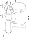
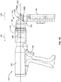
- the system 100 includes a driver 102 to drive a fastener into a structure and a fastener feeder 104 to load the fastener into a loaded position of the driver.
- the fastener feeder 104 includes a fastener magazine 106 to hold a plurality of fasteners.
- the system 100 further includes a driver head 108 including a plurality of jaws 110A-C moveable between a closed position and an expanded position.
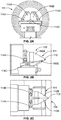
- Figures 2A-C illustrate the plurality of jaws 110A-C in a closed position 111.
- the plurality of jaws 110A-C form a piercing tip 112 to pierce material of the structure into which the fastener is inserted.
- Figures 3A-C illustrate the plurality of jaws 110A-C in an expanded position 113.
- the jaws 110A-C act to spread apart the material of the structure when the jaws 110A-C move from the closed position 111 to the expanded position 113 to create a path through the material through which the fastener is driven. This spreading ensures that the material does not get caught in the hole when the fastener is driven into the structure.
- each jaw 110A-C is spring loaded.
- each jaw includes a spring-loaded hinge 114A-C. The spring-loaded hinges 114A-C act to bias the jaws 110A-C into the closed position.
- Jaws 110A-C may be made from any suitable material.
- the jaws 110A-C comprise metal, so as to allow the jaws to be suitable to spread apart a wide variety of material types.
- Metal may help the jaws 110A-C withstand a large amount of pressure as the jaws spread apart the material of the structure.
- other materials are of course possible as well.
- Figures 1A-3C depict three jaws, more or fewer jaws are possible.
- the driver head 108 includes four or more jaws.
- the driver head 108 includes two jaws. Other examples are possible as well.
- the fastener-installation system 100 is used for driving a fastener into a structure in order to secure different layers of the structure to one another.
- the fastener-installation system 100 may be used for securing cargo-liner panels to an airplane structure.
- An example cargo-liner panel installation process is described with reference to Figure 4 .
- Figure 4 illustrates an example structure 120 into which the faster-installation system 100 may install a fastener, such as fastener 122.
- Example structure 120 includes multiple layers, including at least one panel such as panels 124A-B, foam 126, airplane structure 128, and nut 130.
- the panels 124A-B are fiberglass panels
- foam 126 is foam tape or another compliant material to help prevent fire and smoke migration to other areas of the aircraft
- the airplane structure 128 is a bracket coupled to the airframe.
- Fastener 122 may be inserted into structure 120 in order to secure panels 124A-B to the airplane structure 128.
- the structure 120 includes one panel rather than both panels 124A-B.
- the structure 120 includes at least one layer having a preformed hole and at least one layer without a preformed hole
- fastener-installation system 100 acts to simultaneously (i) spread apart material of the at least one layer without the preformed hole to create a path through the material and (ii) drive a fastener into the structure.
- panel 124a includes preformed holes 132A-C.
- panel 124B, airplane structure 128, and nut 130 also include corresponding preformed holes.
- foam 126 is a layer than does not include a preformed hole.
- fastener-installation system 100 When fastener-installation system 100 is used to drive fastener 122 into structure 120, fastener-installation system 100 acts to simultaneously (i) spread apart foam 126 to create a path through the foam 126 and (ii) drive a fastener into the structure 120 to secure the panels 124A-B to the airplane structure 128.
- fastener 122 is loaded in the fastener-installation system 100, and the driver 102 drives the fastener 122 into the structure 120 upon application of pressure to the driver 102.
- an installer operating fastener-installation system 100 may push a distal end 140 (see Figures 1A-B ) of the fastener-installation system 100 against structure 120.
- the piercing tip 112 pierces foam 126.
- the operator may activate the trigger 142 (see Figures 1A-B ) of the driver 102.
- Activating the trigger 142 causes the driver 102 to rotate a bit (e.g., a screw bit) that engages fastener 122.
- the fastener-installation system 100 includes a telescoping portion 143 that is able to move in proximal direction 145 into body 153 as the operator applies pressure to the distal end 140.
- This compression forces the fastener 122 to be driven through the jaws 110A-C of the driver head 108.
- the jaws 110A-C move from the closed position 111 to the expanded position 113. This movement from the closed position 111 to the expanded position 113 spreads apart foam 126, thereby creating a path through the foam 126 through which the fastener 122 is driven.
- the operator continues to apply pressure to the distal end 140 and the trigger 142 until the fastener 122 is driven through the airplane structure 128 and is threadedly engaged with the nut 130.
- the fastener is threadedly engaged with the nut 130, the panels 124A-B are secured to the airplane structure 128.
- each jaw includes threads located on an inner surface of the jaw to engage with a head of the fastener.
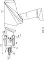
- Figure 5 illustrates a perspective view of driver head 108 and fastener feeder 104 without fastener magazine 106 attached.
- driver head 108 includes threads 147A on inner surface 148A of jaw 110A, threads 147B on inner surface 148B of jaw 110B, and threads 147C on inner surface 148C of jaw 110C.
- These threads 147A-C act to self-center the fastener 122 as the fastener 122 is driven through the plurality of jaws 110A-C and hold the fastener concentric with the screw bit driving the fastener.
- only some of the jaws 110A-C include threads on their inner surfaces.
- the jaws 110A-C do not include threads on their inner surfaces.
- the driver head 108 is connected to a surface of the fastener feeder 104.
- the driver head 108 is connected to distal surface 155.
- the spring loaded hinges 114A-C of jaws 110A-C are connected to the distal surface 155.
- the operator may remove the fastener-installation system 100 from the structure 120.
- the fastener feeder 104 automatically loads a second fastener into the loaded position of the driver after pressure is removed from the driver.
- the distal end 140 decompresses under a biasing force provided by internal spring 144 (see Figure 1B ). Internal spring 144 biases the distal end 140 in the distal direction 146.
- the fastener feeder 104 automatically loads another fastener into a loaded position of the driver 102. Since the fastener feeder automatically loads another fastener, the operator may then immediately install another fastener.
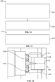
- FIG. 6 depicts a cross-section of fastener feeder 104.
- fastener feeder 104 includes a housing 149 that includes a chamber 151 into which the fastener is loaded.
- Fastener 122 is depicted in a loaded position 150 in chamber 151.
- the fastener feeder 104 may force fastener 152 into the loaded position 150.
- the fastener feeder 104 includes a track 156 to guide the fastener 152 to the loaded position 150 in chamber 151.
- the track 156 includes an opening 158 that exits into the loaded position 150 of chamber 151.
- This opening 158 may be blocked during the installation of fastener 122 (e.g., when telescoping portion 143 is moved in proximal direction 145 (see Figures 1A-B )). However, when pressure is removed from the driver and distal end 140 decompresses as spring 144 (see Figure 1B ) biases the distal end 140 in the distal direction 146, this opening 158 may be unblocked, so as to allow fastener 152 to be loaded into the loaded position 150. Any suitable force to load the fastener 152 into the loaded position 150 may be used.
- the fastener feeder 104 loads the fastener 152 into the loaded position 150 via a biasing force provided by the fastener magazine 106, such as a spring force.
- the fastener feeder 104 may be made from any suitable material.
- the fastener feeder 104 is comprised substantially of plastic.
- the fastener feeder 104, housing 149, chamber 151, and track 156 may be formed substantially of plastic.
- Plastic may help to keep the overall weight of the fastener-installation system 100 low. Other materials are of course possible as well.
- fastener magazine 106 is configured to hold a plurality of fasteners.
- fastener magazine 106 includes an inner body having a spiral track configured to hold at least two rows of fasteners.
- the fastener magazine includes a disc rotatable with respect to the spiral track and having a plurality of cutouts, wherein each cutout spans each row of the at least two rows of fasteners, and wherein rotation of the disc with respect to the spiral track moves the plurality of fasteners through the spiral track.
- fastener magazine 106 is described in greater detail with reference to Figures 7A-10 .
- fastener magazine includes a housing 200 including a lid 202 and main body 204, a disc 206, a spring housing 208 that houses a spring, a key 210, and a central rod 212.
- the main body 204 includes an inner body 214 having a spiral track 216 configured to hold multiple rows of fasteners.
- Spiral track 216 includes a first row 218, a second row 220, and a third row 222. This disclosed spiral arrangement allows the fastener magazine 106 to hold a large number of screws in a compact and lightweight fashion.
- Figures 8A-B depict three rows of fasteners, more or fewer rows are possible.
- the spiral track 216 includes four or more rows.
- the spiral track 216 includes two rows.
- the fastener magazine 106 may be made from any suitable material.
- the fastener magazine 106 is comprised substantially of plastic. Plastic may help to keep the overall weight of the fastener-installation system low. Other materials are of course possible as well.
- Disc 206, spring housing 208, key 210, and central rod 212 are arranged in the housing 200 (see Figure 7B ).
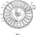
- the disc 206 is rotatable with respect to the spiral track 216 and includes a plurality of cutouts 224 (see Figure 9 ).
- Figure 9 specifically points to three cutouts 224; however, it is clear that disc 206 includes numerous other cutouts.
- each cutout 224 spans each row of the multiple rows of fasteners.
- each cutout 224 spans rows 218, 220, and 222.
- the fasteners are positioned through the cutouts and rotation of the disc 206 with respect to the spiral track 216 moves the plurality of fasteners through the spiral track 216.
- the disc 206 may be configured to rotate in any suitable way in order to advance the fasteners through the spiral track 216.
- a spring is coupled to the disc 206 in order to provide a biasing force to rotate the disc 206.
- spiral torsion spring 226 housed in spring housing 208 and torsion spring 226 provides a biasing force to rotate the disc 206.
- An end 228 of the torsion spring 226 is connected to a rod 229 that is in turn connected to the disc 206. The spring may thus bias the disc 206 to provide rotation.
- the spring 226 rotates the disc 206 to move the screws along the spiral track 216.
- the rotation forces fastener 152 through the track 156 and opening 158 and into the loaded position 150 (see Figure 6 ).
- Fastener magazine 106 may hold any suitable type of screw.
- the fastener magazine 106 holds machine screws, wood screws, sheet metal screws, and/or socket screws.
- fastener magazine 106 is described with respect to screws, in other examples, fastener magazine 106 is configured to hold other fasteners, such as bolts, rivets, nuts, and nails. Other fasteners are possible as well.
- fasteners may have different shapes and sizes. It should be understood that the components of the fastener magazine 106 may be varied to accommodate these different shapes and sizes of various fasteners.
- the depth of the main body 204 is greater for longer fasteners than for shorter fasteners.
- the cutouts 224 of disc 206 are larger for thicker fasteners than thinner fasteners.
- the number of rows of the spiral track 216 is greater for thinner fasteners than for thicker fasteners.
- the fastener magazine 106 is removable from system 100. This allows the operator to replace an empty fastener magazine with a new fastener magazine.
- Figure 11 illustrates a view of the distal end 140 of fastener-installation system 100 where fastener magazine 106 is removed from the system 100.
- the fastener feeder 104 includes a connector 230 that can engage with a corresponding connector of a magazine, such as corresponding connector 232 of magazine 106 (see Figure 9 ).
- Connector 230 and corresponding connector 232 are illustrated as snap-fit connectors. However, any suitable connector may be used.
- connectors 230 and 232 are threads, snap locks, snap fits, luer locks, bayonet, snap rings, or keyed slots. Other connectors are possible as well.
- the fastener magazine is a magazine with a spiral track that holds multiple rows of fasteners
- the system 100 includes a straight-clip magazine.
- Figures 12A-B illustrates an example straight-clip magazine 250.
- the straight-clip magazine 250 includes a spring 252 to bias the fasteners into the loaded position 150.
- straight-clip magazine 250 is configured to hold approximately 15 fasteners
- fastener magazine 106 is configured to hold approximately 50-75 fasteners.
- a straight-clip magazine such as straight-clip magazine 250 may be useful for fitting the system 100 into smaller spaces, such as tight corner spaces, during the installation process.
- Other fastener magazines are possible as well.
- the fastener magazine may be arranged at different angles with respect to the fastener-installation system 100 when the fastener magazine is connected to fastener-installation system 100.
- the fastener magazine 106 is substantially perpendicular to the longitudinal axis 253 of the system 100.
- the fastener magazine may be arranged at different angles with respect to the longitudinal axis 253 of the system 100.
- the connector 254 of magazine 250 is angled such that when the magazine 250 is connected to the corresponding connector 230 of fastener feeder 104, the magazine 250 will be arranged at approximately a 60 degree angle with respect to the longitudinal axis 253.
- the magazine 250 is arranged at an angle between 25-90 degrees with respect to the longitudinal axis 253. In another example, the magazine 250 is arranged at an angle between 25-60 degrees with respect to the longitudinal axis 253. Other angles are possible as well. Arranging the fastener magazine at different angles may be useful for fitting the system 100 into tight spaces during the installation process. For instance, an angle between 25-60 degrees helps to allow the use of the fastener-installation system 100 within the interior of a cargo bay where installers are working inside a cylinder (i.e., the fuselage) and a 90 degree orientation of the fastener magazine 250 would limit the ability to drive fasteners in the lower half of the cylinder (i.e., the belly of the aircraft).
- the fastener feeder 104 and driver head 108 are part of an attachment that removably attaches to driver 102.
- the fastener feeder 104 and driver head 108 are part of attachment 270.
- the attachment 270 includes a main body 272.
- Main body 272 includes telescoping portion 143, body 153, and fastener feeder 104.
- telescoping portion 143 and body 153 are substantially circular; however, other shapes are possible as well.
- the fastener feeder 104 is configured to load a fastener into the loaded position for being driven by driver 102.
- the driver head 108 is located at a distal end 280 of the main body 272.
- the distal end 280 of the main body 272 is the distal end of the fastener feeder 104, and driver head 108 is connected to a distal surface of the fastener feeder 104.
- the main body 272 has a connector 274 to attach to corresponding connector 276 of the driver 102.
- the driver 102 is a screw gun and the corresponding connector 276 includes external threads on the front of the screw gun.
- Other connectors and drivers are possible as well.
- the driver is a rivet gun, a nail gun, an impact wrench, or another impact driver.
- the connectors 274 and 276 are threads, snap locks, snap fits, luer locks, bayonet, snap rings, or keyed slots.
- fastener feeder 104 is attached to a distal end 282 of the telescoping portion 143.
- the distal end 282 of the telescoping portion includes a hole through which a drill bit 284 (see Figure 13 ) can move.
- the housing 149 (see Figure 6 ) of fastener feeder 104 abuts the distal end 282 of the telescoping portion 143, and loaded position 150 of chamber 151 (see Figure 6 ) aligns with the hole of the distal end of telescoping portion 143 through which drill bit 284 can move.
- the fastener feeder 104 includes the telescoping portion 143, and the chamber 151 that holds the fastener in the loaded position 150 is located in the telescoping portion 143. Further, in such an example, at least some portion of track 156 that leads to the loaded position 150 of chamber 151 may be located in the telescoping portion 143.
- the fastener feeder 104 and driver head 108 are part of an attachment 270 that can be removably attached to the driver, in another example of system 100, the fastener feeder 104 and driver head 108 are permanently connected to the driver 102.
- Figure 14 shows a flowchart of an example method 300 for driving a fastener into a structure, where the structure includes at least one layer having a preformed hole and at least one layer without a preformed hole, according to an example.
- Method 300 shown in Figure 14 presents an example of a method that, for example, could be carried out by the fastener-installation system 100 described with reference to Figures 1-12 , for example.
- flowcharts show functionality and operation of one possible implementation of present examples. Alternative implementations are included within the scope of the examples of the present disclosure in which functions may be executed out of order from that shown or discussed, including substantially concurrent or in reverse order, depending on the functionality involved, as would be understood by those reasonably skilled in the art.
- the structure includes at least one layer having a preformed hole and at least one layer without a preformed hole
- the structure includes only layers without any preformed holes.
- the method 300 includes fastener-installation system 100 simultaneously (i) spreading apart material of the at least one layer without the preformed hole to create a path through the material and (ii) driving fastener 122 into the structure 120, wherein spreading apart the material comprises the plurality of jaws 110A-C of the fastener-installation system 100 expanding to spread apart the material.
- the method includes the fastener-installation system 100 loading a second fastener 152 into a loaded position 150 of the fastener-installation system 100 after the fastener-installation system 100 drives the fastener 122 into the structure 120.
- the at least one layer having a preformed hole comprises the panels 124A-B and airplane structure 128 having attached nut 130
- the at least one layer without a preformed hole comprises foam 126 located between the panels 124A-B and the airplane structure 128.
- the method involves (i) the fastener-installation system 100 spreading apart the foam 126 to create a path through the foam 126 and (ii) the fastener-installation system 100 driving the fastener 122 into the panels 124A-B, the foam 126, the airplane structure 128, and the nut 130 to secure the panels 124A-B to the airplane structure 128.
- the plurality of jaws 110A-C of the fastener-installation system 100 expanding to spread apart the material involves jaws 110A-C expanding from closed position 111 to expanded position 113 as the fastener 122 is moved through the jaws 110A-C.
- the fastener-installation system 100 simultaneously spreads apart the material and drives the fastener 122 into the structure 120 as pressure is applied to the fastener-installation system 100. Further, the fastener-installation system 100 loads the second fastener 152 into the loaded position 150 when the pressure is removed from the fastener-installation system 100.
- Figure 15 shows a flowchart of an example method 310 for use with the method 300, according to an example.
- the method includes, prior to the plurality of jaws 110A-C of the fastener-installation system 100 expanding to spread apart the material, the plurality of jaws 110A-C forming a piercing tip 112 and piercing the material with the piercing tip 112.
- the plurality of jaws 110A-C form a piercing tip 112 to pierce material of the structure into which the fastener is inserted.
- the jaws 110A-C form a substantially flat tip rather than a piercing tip.
- Figure 16 illustrates an example of driver head 108 where the plurality of jaws 110A-C form a substantially flat tip 112A in the closed position 111.
- the substantially flat tip 112A is used for a structure in which the material (e.g., foam 126) is the topmost layer.
- the substantially flat tip 112A compresses the foam 126 and the fastener 122 pierces foam 126 as the fastener 122 is driven through the foam 126.
- the jaws 110A-C act to compress the foam 126 when the jaws 110A-C are forced against the foam 126. This compression reduces the thickness of the foam 126, and this reduced thickness helps to prevent the foam 126 from winding around the fastener 122 (e.g., around the threads of the fastener) while the fastener pierces the foam 126.
- the substantially flat tip 112A creates the entire path in the foam 126 through which the fastener is to be driven.
- a user could create a pilot hole or another cut (e.g., one or more radial slits) in the foam 126. The user could then apply pressure to the foam 126 with the substantially flat tip 112A, and, as the jaws 110A-C move to the open position, the jaws would create the hole through which the fastener is driven.
- the hinges 114A-C are spring-loaded radially outward, so that the jaws 110A-C slide radially outward when the jaws 110A-C move from the closed position to the open position.
- Example fastener-installation systems and methods described herein provide improved systems and methods for installing cargo-liner panels.
- the disclosed systems and methods beneficially reduced the number of steps and tools used to clear the foam, insert the fastener, and tighten the fastener to secure the cargo-liner panel to the airplane structure.
- the operator would clear the foam with a first tool, hand insert the fastener, and then thread the fastener with a screw gun.
- the disclosed systems and methods beneficially allow the operator to clear the foam, insert the fastener, and tighten the fastener to secure the panel to the airplane structure in a single step with a single tool. This not only reduces the overall time of the cargo-liner panel installation process but also reduces ergonomic stresses on the operator during the cargo-liner panel installation process.
- the operator would also hand insert the fasteners into the structure prior to driving the fastener with a screw gun.
- the disclosed systems and methods beneficially automatically load fasteners into the driver from a lightweight and compact fastener magazine that can hold a large number of fasteners. Automatically loading the fasteners from the lightweight and compact fastener magazine not only reduces the overall time of the cargo-liner panel installation process but also reduces ergonomic stresses on the operator during the cargo-liner panel installation process. Further, the disclosed fastener magazines also help to reduce or prevent foreign object debris (FOD) during the cargo-liner panel installation process.
- FOD foreign object debris
- fastener-installation systems and methods are described with reference to installation of cargo-liner panels, it should be understood that disclosed systems and methods may be implemented in other systems as well. For instance, the disclosed systems and methods may be implemented in other areas of an aircraft. Further, disclosed systems and methods may be implemented to drive fasteners into structures used in other industries, such as the automotive industry, the construction industry, or the agricultural industry. Other examples are possible as well.
- fastener-installation systems and methods are described primarily with reference to screws, it should be understood that the disclosed fastener-installation systems and methods may use other fasteners as well.
- the fasteners driven by the disclosed fastener-installation systems include bolts, rivets, nuts, and nails. Other fasteners are possible as well.
- any suitable materials may be used for the fastener-installation system including but not limited to metal and plastic.
- the materials are selected to minimize the weight of the fastener-installation system 100, so as to reduce or limit the ergonomic stress on the operator.
Landscapes
- Engineering & Computer Science (AREA)
- Mechanical Engineering (AREA)
- Manufacturing & Machinery (AREA)
- Chemical & Material Sciences (AREA)
- Combustion & Propulsion (AREA)
- Transportation (AREA)
- Aviation & Aerospace Engineering (AREA)
- Portable Nailing Machines And Staplers (AREA)
- Automatic Assembly (AREA)
- Details Of Spanners, Wrenches, And Screw Drivers And Accessories (AREA)
- Connection Of Plates (AREA)
Claims (13)
- Befestigungselement-Installationssystem (100), umfassend:einen Treiber (102), der betreibbar ist, um ein Befestigungselement (122) in eine Struktur einzutreiben;eine Befestigungselement-Zuführeinrichtung (104), die betreibbar ist, um das Befestigungselement (122) in eine Ladeposition (150) des Treibers (102) zu laden, wobei die Befestigungselement-Zuführeinrichtung (104) ein Befestigungselement-Magazin (106) umfasst, um eine Mehrzahl von Befestigungselementen (122) zu halten; undeinen Treiberkopf (108), der eine Mehrzahl von Backen (110A-C) umfasst, die zwischen einer geschlossenen Position (111) und einer expandierten Position (113) bewegbar sind, wobei in der geschlossenen Position (111) die Mehrzahl von Backen (110A-C) eine Durchstechspitze (112) bilden, um das Material der Struktur zu durchstechen, und wobei die Backen (110A-C) das Material der Struktur auseinanderspreizen, wenn sich die Backen (110A-C) von der geschlossenen Position (111) in die expandierte Position (113) bewegen, um einen Pfad durch das Material zu erzeugen, durch den das Befestigungselement (122) getrieben wird,wobei das Befestigungselement-Installationssystem so eingerichtet ist, dass sich die Mehrzahl von Backen (110A-C) von der geschlossenen Position (111) in die expandierte Position (113) bewegt, wenn das Befestigungselement (122) durch die Mehrzahl von Backen (110A-C) hindurchgetrieben wird, unddadurch gekennzeichnet, dassjeder Backen der Mehrzahl von Backen (110A-C) ein Gewinde (147A-C) aufweist, das an einer Innenfläche (148A-C) des Backens angeordnet ist, um mit einem Kopf des Befestigungselements (122) in Eingriff zu kommen, wobei die Gewinde (147A-C) betreibbar sind, um eine Selbstzentrierung des Befestigungselements (122) zu bewirken, wenn das Befestigungselement (122) durch die Mehrzahl von Backen (110A-C) hindurchgetrieben wird.
- Befestigungselement-Installationssystem (100) nach Anspruch 1, bei dem der Treiber (102) betreibbar ist, um das Befestigungselement (122) in die Struktur einzutreiben, wenn Druck auf den Treiber (102) ausgeübt wird, und bei dem die Befestigungselement-Zuführeinrichtung (104) automatisch betreibbar ist, um ein zweites Befestigungselement (152) in die Ladeposition (150) des Treibers (102) zu laden, nachdem das Befestigungselement (122) in die Struktur eingetrieben wurde und der Druck vom Treiber (102) genommen wurde.
- Befestigungselement-Installationssystem (100) nach Anspruch 2, bei dem die Befestigungselement-Zuführvorrichtung (104) eine Feder (144) umfasst, die betreibbar ist, um das zweite Befestigungselement (152) in die Ladeposition (150) des Treibers (102) zu beaufschlagen, nachdem das Befestigungselement (122) in die Struktur eingetrieben und der Druck von dem Treiber (102) genommen wurde.
- Befestigungselement-Installationssystem (100) nach einem der Ansprüche 1 bis 3, bei dem das Befestigungselement-Magazin (106) einen Innenkörper (214) mit einer Schraubenbahn (216) umfasst, die konfiguriert ist, um mindestens zwei Reihen von Befestigungselementen (122) zu halten.
- Befestigungselement-Installationssystem (100) nach Anspruch 4, das ferner eine Scheibe (206) umfasst, die in Bezug auf die Schraubenbahn (216) drehbar ist und eine Mehrzahl von Ausschnitten aufweist, wobei jeder Ausschnitt jede Reihe der mindestens zwei Reihen von Befestigungselementen (122) überspannt, und wobei die Drehung der Scheibe (206) in Bezug auf die Schraubenbahn (216) die Mehrzahl von Befestigungselementen (122) durch die Schraubenbahn (216) bewegt.
- Befestigungselement-Installationssystem (100) nach einem der Ansprüche 1 bis 5, bei dem der Treiber (102) eine Schraubpistole umfasst, und bei dem der Treiberkopf (108) und die Befestigungselement-Zuführung (104) Teil eines abnehmbaren Aufsatzes sind, der abnehmbar an der Schraubpistole angebracht ist.
- Befestigungselement-Installationssystem (100) nach einem der Ansprüche 1-6, bei dem das Befestigungselement-Magazin (106) unter einem Winkel zwischen 25-60 Grad in Bezug auf eine Längsachse des Befestigungselement-Installationssystems (100) angeordnet ist.
- Halterung für einen Treiber (102), wobei die Halterung umfasst:einen Hauptkörper mit einem Verbinder, der konfiguriert ist, um an einem entsprechenden Verbinder des Treibers (102) angebracht zu werden;eine Befestigungsmittel-Zuführeinrichtung (104), die betreibbar ist, um ein Befestigungsmittel (122) in eine Ladeposition (150) zu laden, um durch den Treiber (102) angetrieben zu werden, wobei die Befestigungsmittel-Zuführeinrichtung (104) ein Befestigungsmittelmagazin (106) zum Halten einer Mehrzahl von Befestigungsmitteln (122) umfasst; undeinen Treiberkopf (108), der an einem distalen Ende des Hauptkörpers angeordnet ist, wobei der Treiberkopf (108) eine Mehrzahl von Backen (110A-C) umfasst, die zwischen einer geschlossenen Position (111) und einer expandierten Position (113) bewegbar sind, wobei in der geschlossenen Position (111) die Mehrzahl von Backen (110A-C) eine Durchstechspitze (112) bilden, um Material einer Struktur zu durchstechen, und wobei die Backen (110A-C) Material der Struktur auseinanderspreizen, wenn sich die Backen (110A-C) von der geschlossenen Position (111) in die expandierte Position (113) bewegen, um einen Pfad durch das Material zu erzeugen, durch den das Befestigungselement (122) getrieben wird,wobei die Mehrzahl der Backen (110A-C) in Eingriff stehen, um sich von der geschlossenen Position (111) in die expandierte Position (113) zu bewegen, wenn das Befestigungselement (122) durch die Mehrzahl der Backen (110A-C) getrieben wird, unddadurch gekennzeichnet, dassjeder Backen der Mehrzahl von Backen (110A-C) Gewinde (147A-C) aufweist, die an einer Innenfläche (148A-C) des Backens angeordnet ist, um mit einem Kopf des Befestigungselements (122) in Eingriff zu kommen, wobei die Gewinde (147A-C) betreibbar sind, um eine Selbstzentrierung des Befestigungselements (122) zu bewirken, wenn das Befestigungselement (122) durch die Mehrzahl von Backen (110A-C) hindurchgetrieben wird.
- Halterung nach Anspruch 8, bei der das Befestigungsmittelmagazin (106) einen Innenkörper (214) umfasst, der eine Schraubenbahn (216) aufweist, die konfiguriert ist, um mindestens zwei Reihen von Befestigungsmitteln (122) zu halten.
- Halterung nach Anspruch 9, ferner mit einer Scheibe (206), die in Bezug auf die Schraubenbahn (216) drehbar ist und eine Mehrzahl von Ausschnitten aufweist, wobei jeder Ausschnitt jede Reihe der mindestens zwei Reihen von Befestigungselementen (122) überspannt, und wobei die Drehung der Scheibe (206) in Bezug auf die Schraubenbahn (216) die Mehrzahl von Befestigungselementen (122) durch die Schraubenbahn (216) bewegt.
- Verfahren (300) zum Eintreiben eines Befestigungselements in eine Struktur, wobei die Struktur mindestens eine Schicht mit einem vorgeformten Loch und mindestens eine Schicht ohne ein vorgeformtes Loch umfasst, wobei das Verfahren umfasst:gleichzeitiges (i) Auseinanderspreizen (302) von Material der mindestens einen Schicht ohne das vorgeformte Loch durch das Befestigungselement-Installationssystem, um einen Weg durch das Material zu erzeugen, und (ii) Eintreiben eines Befestigungselements in die Struktur, wobei das Auseinanderspreizen des Materials das Expandieren einer Mehrzahl von Backen des Befestigungselement-Installationssystems umfasst, um das Material auseinanderzuspreizen; undLaden eines zweiten Befestigungselements in eine Ladeposition des Befestigungselement-Installationssystems durch das Befestigungselement-Installationssystem (304), nachdem das Befestigungselement-Installationssystem das Befestigungselement in die Struktur eingetrieben hat,wobei das Befestigungselement-Installationssystem so eingerichtet ist, dass sich die Mehrzahl von Backen (110A-C) von der geschlossenen Position (111) in die expandierte Position (113) bewegt, wenn das Befestigungselement (122) durch die Mehrzahl von Backen (110A-C) hindurchgetrieben wird, unddadurch gekennzeichnet, dassjeder Backen der Mehrzahl von Backen (110A-C) ein Gewinde (147A-C) aufweist, das an einer Innenfläche (148A-C) des Backens angeordnet ist, um mit einem Kopf des Befestigungselements (122) in Eingriff zu kommen, wobei das Gewinde (147A-C) betreibbar ist, um eine Selbstzentrierung des Befestigungselements (122) zu bewirken, wenn das Befestigungselement (122) durch die Mehrzahl von Backen (110A-C) getrieben wird.
- Verfahren nach Anspruch 11, bei dem das gleichzeitige (i) Auseinanderspreizen des Materials der mindestens einen Schicht ohne das vorgeformte Loch, um einen Weg durch das Material zu schaffen, und (ii) Eintreiben des Befestigungselements in die Struktur das Auseinanderspreizen des Materials und das Eintreiben des Befestigungselements in die Struktur umfasst, wenn Druck auf das Befestigungselement-Installationssystem ausgeübt wird, und
wobei das Laden eines zweiten Befestigungselements in eine Ladeposition des Befestigungselement-Installationssystems durch das Befestigungselement-Installationssystem das Laden des zweiten Befestigungselements in die Ladeposition, wenn der Druck von dem Befestigungselement-Installationssystem genommen wird, umfasst. - Verfahren nach Anspruch 11 oder 12, bei dem die mindestens eine Schicht mit vorgeformtem Loch mindestens eine Platte und eine Flugzeugstruktur mit einer angebrachten Mutter umfasst, wobei die mindestens eine Schicht ohne vorgeformtes Loch Schaumstoff umfasst, der zwischen der mindestens einen Platte und der Flugzeugstruktur mit der angebrachten Mutter angeordnet ist, und wobei das gleichzeitige Auseinanderspreizen (i) von Material der mindestens einen Schicht ohne ein vorgeformtes Loch, um einen Pfad durch das Material zu erzeugen, und (ii) das Eintreiben des Befestigungselements in die Struktur durch das Befestigungselement-Installationssystem umfasst:Auseinanderspreizen des Schaums durch das Befestigungselement-Installationssystem, um einen Weg durch den Schaum zu erzeugen; undEintreiben des Befestigungselements in die mindestens eine Platte, den Schaum, die Flugzeugstruktur und die Mutter durch das Befestigungselement-Installationssystem, um die mindestens eine Platte an der Flugzeugstruktur zu befestigen.
Applications Claiming Priority (1)
| Application Number | Priority Date | Filing Date | Title |
|---|---|---|---|
| US15/418,967 US10751859B2 (en) | 2017-01-30 | 2017-01-30 | Fastener-installation systems and methods |
Publications (2)
| Publication Number | Publication Date |
|---|---|
| EP3354407A1 EP3354407A1 (de) | 2018-08-01 |
| EP3354407B1 true EP3354407B1 (de) | 2021-02-03 |
Family
ID=60627423
Family Applications (1)
| Application Number | Title | Priority Date | Filing Date |
|---|---|---|---|
| EP17204947.0A Active EP3354407B1 (de) | 2017-01-30 | 2017-12-01 | Befestigungselement-installationssysteme und verfahren dafür |
Country Status (5)
| Country | Link |
|---|---|
| US (1) | US10751859B2 (de) |
| EP (1) | EP3354407B1 (de) |
| JP (1) | JP2018126855A (de) |
| CN (1) | CN108372481B (de) |
| CA (1) | CA2985926C (de) |
Families Citing this family (4)
| Publication number | Priority date | Publication date | Assignee | Title |
|---|---|---|---|---|
| SE541414C2 (sv) * | 2016-09-01 | 2019-09-24 | Ruben Haegglunds Maskin Ab | Bandupprullare |
| USD951741S1 (en) | 2020-10-14 | 2022-05-17 | Simpson Strong-Tie Company Inc. | Screw driving tool |
| USD951050S1 (en) | 2020-10-14 | 2022-05-10 | Simpson Strong-Tie Company Inc. | Fastener driving tool adapter |
| US20240025024A1 (en) * | 2022-07-25 | 2024-01-25 | David Sosa | Cordless electric coil roofing nail gun apparatus |
Family Cites Families (16)
| Publication number | Priority date | Publication date | Assignee | Title |
|---|---|---|---|---|
| US3398446A (en) * | 1963-09-17 | 1968-08-27 | Sandvikens Jernberks Aktiebola | Device for applying traction-augmenting studs in tires for vehicles and the like |
| US3710835A (en) * | 1971-07-09 | 1973-01-16 | J Eby | Screwdriver with screw holding attachment |
| US3854648A (en) * | 1972-10-04 | 1974-12-17 | G Inzoli | Air operated fastener driving tool, especially for tacks |
| US4476749A (en) * | 1980-08-19 | 1984-10-16 | Titan Tool Company | Automatic stud driver |
| JPS62141481U (de) * | 1986-02-27 | 1987-09-07 | ||
| JPH02232178A (ja) * | 1989-03-06 | 1990-09-14 | Masaki Kawashima | ファスナー締結機 |
| JPH08229847A (ja) * | 1995-02-28 | 1996-09-10 | Max Co Ltd | 釘打機用アタッチメント |
| US5897045A (en) * | 1997-09-12 | 1999-04-27 | Illinois Tool Works Inc. | Fastener dispensing apparatus for stand-up fastener driving tool and method therefor |
| US6609646B2 (en) * | 2001-02-08 | 2003-08-26 | Black & Decker Inc. | Magazine assembly for fastening tool |
| JP2004090210A (ja) * | 2002-07-12 | 2004-03-25 | Hitachi Koki Co Ltd | ねじ締め機 |
| US20050150148A1 (en) | 2003-12-23 | 2005-07-14 | Herpel Michael J. | Easy loading gun magazine |
| JP4577495B2 (ja) * | 2004-11-26 | 2010-11-10 | マックス株式会社 | ネジ、釘等の打込機における打込ガイド機構 |
| US7137186B2 (en) * | 2004-12-03 | 2006-11-21 | Black & Decker Inc. | Magazine for wired-collated fasteners with automatic loading |
| AU2008248412B2 (en) * | 2007-05-07 | 2014-09-18 | Simpson Strong-Tie Company, Inc. | Fastener driving system with precision fastener guide |
| JP2011194557A (ja) * | 2010-03-17 | 2011-10-06 | Asami Sekkei Jimusho:Kk | 自動供給ビス締め機 |
| CN105881437A (zh) * | 2014-11-25 | 2016-08-24 | 常州市沁惠机械厂 | 全自动螺丝刀架 |
-
2017
- 2017-01-30 US US15/418,967 patent/US10751859B2/en active Active
- 2017-11-16 CA CA2985926A patent/CA2985926C/en active Active
- 2017-12-01 EP EP17204947.0A patent/EP3354407B1/de active Active
- 2017-12-12 JP JP2017237413A patent/JP2018126855A/ja active Pending
- 2017-12-19 CN CN201711371768.XA patent/CN108372481B/zh active Active
Non-Patent Citations (1)
| Title |
|---|
| None * |
Also Published As
| Publication number | Publication date |
|---|---|
| CA2985926A1 (en) | 2018-07-30 |
| JP2018126855A (ja) | 2018-08-16 |
| CA2985926C (en) | 2022-11-29 |
| US10751859B2 (en) | 2020-08-25 |
| EP3354407A1 (de) | 2018-08-01 |
| CN108372481A (zh) | 2018-08-07 |
| US20180215018A1 (en) | 2018-08-02 |
| CN108372481B (zh) | 2022-03-11 |
Similar Documents
| Publication | Publication Date | Title |
|---|---|---|
| CA2985926C (en) | Fastener-installation systems and methods | |
| US6862963B2 (en) | Split nosepiece for driving collated screws | |
| US11370036B2 (en) | One up assembly aircraft panel drilling system | |
| DE69608999T2 (de) | Tragbares, gasbetätigtes Befestigungswerkzeug | |
| DE69010319T2 (de) | Robotergesteuertes Multitask-Greiforgan. | |
| DE2042769C3 (de) | Mit Nägeln bestücktes Magazin für ein pulverkraftbetriebenes Setzgerät | |
| CA2189027C (en) | Screw strip with overlapping washers, and method and apparatus for installation | |
| US20150102086A1 (en) | Clenching adapter for automatic nailers | |
| US11867213B2 (en) | Temporary fastener for structures | |
| US20180223547A1 (en) | Hidden clip and fastening system for decking | |
| US9586257B2 (en) | Combination collar feeder and swaging tool | |
| WO1997025538A9 (en) | Tacking fastener | |
| WO1997025538A1 (en) | Tacking fastener | |
| DE102010062368A1 (de) | Eintreiber für Befestigungselemente mit Sperrglied einer Eintreibbaugruppe | |
| US8893594B2 (en) | Fastener extraction device | |
| GB2419168A (en) | Expansion fastener assembly | |
| EP4541980A2 (de) | Wandanker mit verformbarem spreizteil | |
| US4726504A (en) | Portable self-piercing riveting apparatus | |
| CA1117251A (en) | Nozzle assembly | |
| DE3715293C2 (de) | ||
| EP1445070B1 (de) | Spannvorrichtung zur Befestigung eines Werkzeugs an einer mehrschichtigen Baugruppe unter Verwendung eines provisorischen Befestigungselements welches an der Baugruppe angebracht ist | |
| EP1892061B1 (de) | Nagelgerät, Hilfsstück dafür und Arbeitsweise | |
| US12186869B2 (en) | Powered fastener driving tool | |
| US3041616A (en) | Fastening apparatus | |
| US8844785B2 (en) | Powered stapler and method of operating same |
Legal Events
| Date | Code | Title | Description |
|---|---|---|---|
| PUAI | Public reference made under article 153(3) epc to a published international application that has entered the european phase |
Free format text: ORIGINAL CODE: 0009012 |
|
| STAA | Information on the status of an ep patent application or granted ep patent |
Free format text: STATUS: REQUEST FOR EXAMINATION WAS MADE |
|
| 17P | Request for examination filed |
Effective date: 20171201 |
|
| AK | Designated contracting states |
Kind code of ref document: A1 Designated state(s): AL AT BE BG CH CY CZ DE DK EE ES FI FR GB GR HR HU IE IS IT LI LT LU LV MC MK MT NL NO PL PT RO RS SE SI SK SM TR |
|
| AX | Request for extension of the european patent |
Extension state: BA ME |
|
| GRAP | Despatch of communication of intention to grant a patent |
Free format text: ORIGINAL CODE: EPIDOSNIGR1 |
|
| STAA | Information on the status of an ep patent application or granted ep patent |
Free format text: STATUS: GRANT OF PATENT IS INTENDED |
|
| INTG | Intention to grant announced |
Effective date: 20200821 |
|
| GRAS | Grant fee paid |
Free format text: ORIGINAL CODE: EPIDOSNIGR3 |
|
| GRAA | (expected) grant |
Free format text: ORIGINAL CODE: 0009210 |
|
| STAA | Information on the status of an ep patent application or granted ep patent |
Free format text: STATUS: THE PATENT HAS BEEN GRANTED |
|
| AK | Designated contracting states |
Kind code of ref document: B1 Designated state(s): AL AT BE BG CH CY CZ DE DK EE ES FI FR GB GR HR HU IE IS IT LI LT LU LV MC MK MT NL NO PL PT RO RS SE SI SK SM TR |
|
| REG | Reference to a national code |
Ref country code: GB Ref legal event code: FG4D |
|
| REG | Reference to a national code |
Ref country code: AT Ref legal event code: REF Ref document number: 1359591 Country of ref document: AT Kind code of ref document: T Effective date: 20210215 Ref country code: CH Ref legal event code: EP |
|
| REG | Reference to a national code |
Ref country code: DE Ref legal event code: R096 Ref document number: 602017032330 Country of ref document: DE |
|
| REG | Reference to a national code |
Ref country code: IE Ref legal event code: FG4D |
|
| REG | Reference to a national code |
Ref country code: NL Ref legal event code: MP Effective date: 20210203 |
|
| REG | Reference to a national code |
Ref country code: LT Ref legal event code: MG9D |
|
| REG | Reference to a national code |
Ref country code: AT Ref legal event code: MK05 Ref document number: 1359591 Country of ref document: AT Kind code of ref document: T Effective date: 20210203 |
|
| PG25 | Lapsed in a contracting state [announced via postgrant information from national office to epo] |
Ref country code: LT Free format text: LAPSE BECAUSE OF FAILURE TO SUBMIT A TRANSLATION OF THE DESCRIPTION OR TO PAY THE FEE WITHIN THE PRESCRIBED TIME-LIMIT Effective date: 20210203 Ref country code: BG Free format text: LAPSE BECAUSE OF FAILURE TO SUBMIT A TRANSLATION OF THE DESCRIPTION OR TO PAY THE FEE WITHIN THE PRESCRIBED TIME-LIMIT Effective date: 20210503 Ref country code: NO Free format text: LAPSE BECAUSE OF FAILURE TO SUBMIT A TRANSLATION OF THE DESCRIPTION OR TO PAY THE FEE WITHIN THE PRESCRIBED TIME-LIMIT Effective date: 20210503 Ref country code: PT Free format text: LAPSE BECAUSE OF FAILURE TO SUBMIT A TRANSLATION OF THE DESCRIPTION OR TO PAY THE FEE WITHIN THE PRESCRIBED TIME-LIMIT Effective date: 20210604 Ref country code: HR Free format text: LAPSE BECAUSE OF FAILURE TO SUBMIT A TRANSLATION OF THE DESCRIPTION OR TO PAY THE FEE WITHIN THE PRESCRIBED TIME-LIMIT Effective date: 20210203 Ref country code: GR Free format text: LAPSE BECAUSE OF FAILURE TO SUBMIT A TRANSLATION OF THE DESCRIPTION OR TO PAY THE FEE WITHIN THE PRESCRIBED TIME-LIMIT Effective date: 20210504 Ref country code: FI Free format text: LAPSE BECAUSE OF FAILURE TO SUBMIT A TRANSLATION OF THE DESCRIPTION OR TO PAY THE FEE WITHIN THE PRESCRIBED TIME-LIMIT Effective date: 20210203 |
|
| PG25 | Lapsed in a contracting state [announced via postgrant information from national office to epo] |
Ref country code: SE Free format text: LAPSE BECAUSE OF FAILURE TO SUBMIT A TRANSLATION OF THE DESCRIPTION OR TO PAY THE FEE WITHIN THE PRESCRIBED TIME-LIMIT Effective date: 20210203 Ref country code: AT Free format text: LAPSE BECAUSE OF FAILURE TO SUBMIT A TRANSLATION OF THE DESCRIPTION OR TO PAY THE FEE WITHIN THE PRESCRIBED TIME-LIMIT Effective date: 20210203 Ref country code: RS Free format text: LAPSE BECAUSE OF FAILURE TO SUBMIT A TRANSLATION OF THE DESCRIPTION OR TO PAY THE FEE WITHIN THE PRESCRIBED TIME-LIMIT Effective date: 20210203 Ref country code: LV Free format text: LAPSE BECAUSE OF FAILURE TO SUBMIT A TRANSLATION OF THE DESCRIPTION OR TO PAY THE FEE WITHIN THE PRESCRIBED TIME-LIMIT Effective date: 20210203 Ref country code: NL Free format text: LAPSE BECAUSE OF FAILURE TO SUBMIT A TRANSLATION OF THE DESCRIPTION OR TO PAY THE FEE WITHIN THE PRESCRIBED TIME-LIMIT Effective date: 20210203 Ref country code: PL Free format text: LAPSE BECAUSE OF FAILURE TO SUBMIT A TRANSLATION OF THE DESCRIPTION OR TO PAY THE FEE WITHIN THE PRESCRIBED TIME-LIMIT Effective date: 20210203 |
|
| PG25 | Lapsed in a contracting state [announced via postgrant information from national office to epo] |
Ref country code: IS Free format text: LAPSE BECAUSE OF FAILURE TO SUBMIT A TRANSLATION OF THE DESCRIPTION OR TO PAY THE FEE WITHIN THE PRESCRIBED TIME-LIMIT Effective date: 20210603 |
|
| PG25 | Lapsed in a contracting state [announced via postgrant information from national office to epo] |
Ref country code: CZ Free format text: LAPSE BECAUSE OF FAILURE TO SUBMIT A TRANSLATION OF THE DESCRIPTION OR TO PAY THE FEE WITHIN THE PRESCRIBED TIME-LIMIT Effective date: 20210203 Ref country code: EE Free format text: LAPSE BECAUSE OF FAILURE TO SUBMIT A TRANSLATION OF THE DESCRIPTION OR TO PAY THE FEE WITHIN THE PRESCRIBED TIME-LIMIT Effective date: 20210203 Ref country code: SM Free format text: LAPSE BECAUSE OF FAILURE TO SUBMIT A TRANSLATION OF THE DESCRIPTION OR TO PAY THE FEE WITHIN THE PRESCRIBED TIME-LIMIT Effective date: 20210203 |
|
| REG | Reference to a national code |
Ref country code: DE Ref legal event code: R097 Ref document number: 602017032330 Country of ref document: DE |
|
| PG25 | Lapsed in a contracting state [announced via postgrant information from national office to epo] |
Ref country code: RO Free format text: LAPSE BECAUSE OF FAILURE TO SUBMIT A TRANSLATION OF THE DESCRIPTION OR TO PAY THE FEE WITHIN THE PRESCRIBED TIME-LIMIT Effective date: 20210203 Ref country code: SK Free format text: LAPSE BECAUSE OF FAILURE TO SUBMIT A TRANSLATION OF THE DESCRIPTION OR TO PAY THE FEE WITHIN THE PRESCRIBED TIME-LIMIT Effective date: 20210203 Ref country code: DK Free format text: LAPSE BECAUSE OF FAILURE TO SUBMIT A TRANSLATION OF THE DESCRIPTION OR TO PAY THE FEE WITHIN THE PRESCRIBED TIME-LIMIT Effective date: 20210203 |
|
| PLBE | No opposition filed within time limit |
Free format text: ORIGINAL CODE: 0009261 |
|
| STAA | Information on the status of an ep patent application or granted ep patent |
Free format text: STATUS: NO OPPOSITION FILED WITHIN TIME LIMIT |
|
| 26N | No opposition filed |
Effective date: 20211104 |
|
| PG25 | Lapsed in a contracting state [announced via postgrant information from national office to epo] |
Ref country code: ES Free format text: LAPSE BECAUSE OF FAILURE TO SUBMIT A TRANSLATION OF THE DESCRIPTION OR TO PAY THE FEE WITHIN THE PRESCRIBED TIME-LIMIT Effective date: 20210203 Ref country code: AL Free format text: LAPSE BECAUSE OF FAILURE TO SUBMIT A TRANSLATION OF THE DESCRIPTION OR TO PAY THE FEE WITHIN THE PRESCRIBED TIME-LIMIT Effective date: 20210203 |
|
| PG25 | Lapsed in a contracting state [announced via postgrant information from national office to epo] |
Ref country code: SI Free format text: LAPSE BECAUSE OF FAILURE TO SUBMIT A TRANSLATION OF THE DESCRIPTION OR TO PAY THE FEE WITHIN THE PRESCRIBED TIME-LIMIT Effective date: 20210203 |
|
| PG25 | Lapsed in a contracting state [announced via postgrant information from national office to epo] |
Ref country code: IT Free format text: LAPSE BECAUSE OF FAILURE TO SUBMIT A TRANSLATION OF THE DESCRIPTION OR TO PAY THE FEE WITHIN THE PRESCRIBED TIME-LIMIT Effective date: 20210203 |
|
| PG25 | Lapsed in a contracting state [announced via postgrant information from national office to epo] |
Ref country code: IS Free format text: LAPSE BECAUSE OF FAILURE TO SUBMIT A TRANSLATION OF THE DESCRIPTION OR TO PAY THE FEE WITHIN THE PRESCRIBED TIME-LIMIT Effective date: 20210603 |
|
| PG25 | Lapsed in a contracting state [announced via postgrant information from national office to epo] |
Ref country code: MC Free format text: LAPSE BECAUSE OF FAILURE TO SUBMIT A TRANSLATION OF THE DESCRIPTION OR TO PAY THE FEE WITHIN THE PRESCRIBED TIME-LIMIT Effective date: 20210203 |
|
| REG | Reference to a national code |
Ref country code: CH Ref legal event code: PL |
|
| REG | Reference to a national code |
Ref country code: BE Ref legal event code: MM Effective date: 20211231 |
|
| PG25 | Lapsed in a contracting state [announced via postgrant information from national office to epo] |
Ref country code: LU Free format text: LAPSE BECAUSE OF NON-PAYMENT OF DUE FEES Effective date: 20211201 Ref country code: IE Free format text: LAPSE BECAUSE OF NON-PAYMENT OF DUE FEES Effective date: 20211201 |
|
| PG25 | Lapsed in a contracting state [announced via postgrant information from national office to epo] |
Ref country code: BE Free format text: LAPSE BECAUSE OF NON-PAYMENT OF DUE FEES Effective date: 20211231 |
|
| PG25 | Lapsed in a contracting state [announced via postgrant information from national office to epo] |
Ref country code: LI Free format text: LAPSE BECAUSE OF NON-PAYMENT OF DUE FEES Effective date: 20211231 Ref country code: CH Free format text: LAPSE BECAUSE OF NON-PAYMENT OF DUE FEES Effective date: 20211231 |
|
| PG25 | Lapsed in a contracting state [announced via postgrant information from national office to epo] |
Ref country code: HU Free format text: LAPSE BECAUSE OF FAILURE TO SUBMIT A TRANSLATION OF THE DESCRIPTION OR TO PAY THE FEE WITHIN THE PRESCRIBED TIME-LIMIT; INVALID AB INITIO Effective date: 20171201 |
|
| P01 | Opt-out of the competence of the unified patent court (upc) registered |
Effective date: 20230516 |
|
| PG25 | Lapsed in a contracting state [announced via postgrant information from national office to epo] |
Ref country code: CY Free format text: LAPSE BECAUSE OF FAILURE TO SUBMIT A TRANSLATION OF THE DESCRIPTION OR TO PAY THE FEE WITHIN THE PRESCRIBED TIME-LIMIT Effective date: 20210203 |
|
| PG25 | Lapsed in a contracting state [announced via postgrant information from national office to epo] |
Ref country code: MK Free format text: LAPSE BECAUSE OF FAILURE TO SUBMIT A TRANSLATION OF THE DESCRIPTION OR TO PAY THE FEE WITHIN THE PRESCRIBED TIME-LIMIT Effective date: 20210203 |
|
| PG25 | Lapsed in a contracting state [announced via postgrant information from national office to epo] |
Ref country code: TR Free format text: LAPSE BECAUSE OF FAILURE TO SUBMIT A TRANSLATION OF THE DESCRIPTION OR TO PAY THE FEE WITHIN THE PRESCRIBED TIME-LIMIT Effective date: 20210203 |
|
| PG25 | Lapsed in a contracting state [announced via postgrant information from national office to epo] |
Ref country code: MT Free format text: LAPSE BECAUSE OF FAILURE TO SUBMIT A TRANSLATION OF THE DESCRIPTION OR TO PAY THE FEE WITHIN THE PRESCRIBED TIME-LIMIT Effective date: 20210203 |
|
| PGFP | Annual fee paid to national office [announced via postgrant information from national office to epo] |
Ref country code: GB Payment date: 20251229 Year of fee payment: 9 |
|
| PGFP | Annual fee paid to national office [announced via postgrant information from national office to epo] |
Ref country code: FR Payment date: 20251226 Year of fee payment: 9 |
|
| PGFP | Annual fee paid to national office [announced via postgrant information from national office to epo] |
Ref country code: DE Payment date: 20251229 Year of fee payment: 9 |