EP3354213A1 - Applikator zum einbringen einer substanz in eine körperhöhle - Google Patents
Applikator zum einbringen einer substanz in eine körperhöhle Download PDFInfo
- Publication number
- EP3354213A1 EP3354213A1 EP17000123.4A EP17000123A EP3354213A1 EP 3354213 A1 EP3354213 A1 EP 3354213A1 EP 17000123 A EP17000123 A EP 17000123A EP 3354213 A1 EP3354213 A1 EP 3354213A1
- Authority
- EP
- European Patent Office
- Prior art keywords
- needle
- nozzle
- substance
- applicator according
- body cavity
- Prior art date
- Legal status (The legal status is an assumption and is not a legal conclusion. Google has not performed a legal analysis and makes no representation as to the accuracy of the status listed.)
- Granted
Links
- 239000000126 substance Substances 0.000 title claims abstract description 26
- 239000000443 aerosol Substances 0.000 claims description 4
- 230000001419 dependent effect Effects 0.000 claims description 4
- 238000005086 pumping Methods 0.000 claims 3
- 239000007789 gas Substances 0.000 description 5
- CURLTUGMZLYLDI-UHFFFAOYSA-N Carbon dioxide Chemical compound O=C=O CURLTUGMZLYLDI-UHFFFAOYSA-N 0.000 description 2
- 238000002357 laparoscopic surgery Methods 0.000 description 2
- 239000004480 active ingredient Substances 0.000 description 1
- 230000005540 biological transmission Effects 0.000 description 1
- 230000015572 biosynthetic process Effects 0.000 description 1
- 229910002092 carbon dioxide Inorganic materials 0.000 description 1
- 239000001569 carbon dioxide Substances 0.000 description 1
- 239000012159 carrier gas Substances 0.000 description 1
- 239000003814 drug Substances 0.000 description 1
- 229940079593 drug Drugs 0.000 description 1
- 230000000694 effects Effects 0.000 description 1
Images
Classifications
-
- A—HUMAN NECESSITIES
- A61—MEDICAL OR VETERINARY SCIENCE; HYGIENE
- A61B—DIAGNOSIS; SURGERY; IDENTIFICATION
- A61B17/00—Surgical instruments, devices or methods, e.g. tourniquets
- A61B17/34—Trocars; Puncturing needles
- A61B17/3474—Insufflating needles, e.g. Veress needles
-
- A—HUMAN NECESSITIES
- A61—MEDICAL OR VETERINARY SCIENCE; HYGIENE
- A61M—DEVICES FOR INTRODUCING MEDIA INTO, OR ONTO, THE BODY; DEVICES FOR TRANSDUCING BODY MEDIA OR FOR TAKING MEDIA FROM THE BODY; DEVICES FOR PRODUCING OR ENDING SLEEP OR STUPOR
- A61M11/00—Sprayers or atomisers specially adapted for therapeutic purposes
- A61M11/02—Sprayers or atomisers specially adapted for therapeutic purposes operated by air or other gas pressure applied to the liquid or other product to be sprayed or atomised
-
- A—HUMAN NECESSITIES
- A61—MEDICAL OR VETERINARY SCIENCE; HYGIENE
- A61M—DEVICES FOR INTRODUCING MEDIA INTO, OR ONTO, THE BODY; DEVICES FOR TRANSDUCING BODY MEDIA OR FOR TAKING MEDIA FROM THE BODY; DEVICES FOR PRODUCING OR ENDING SLEEP OR STUPOR
- A61M13/00—Insufflators for therapeutic or disinfectant purposes, i.e. devices for blowing a gas, powder or vapour into the body
- A61M13/003—Blowing gases other than for carrying powders, e.g. for inflating, dilating or rinsing
-
- A—HUMAN NECESSITIES
- A61—MEDICAL OR VETERINARY SCIENCE; HYGIENE
- A61M—DEVICES FOR INTRODUCING MEDIA INTO, OR ONTO, THE BODY; DEVICES FOR TRANSDUCING BODY MEDIA OR FOR TAKING MEDIA FROM THE BODY; DEVICES FOR PRODUCING OR ENDING SLEEP OR STUPOR
- A61M2202/00—Special media to be introduced, removed or treated
- A61M2202/02—Gases
- A61M2202/0225—Carbon oxides, e.g. Carbon dioxide
Definitions
- Applicator with my trocar a trained in the trocar sleeve through hole and a guided in operation in the through hole of the trocar sleeve needle, at the distal end portion of a needle nozzle is formed.
- Such an applicator is off, for example DE 10 2012 104 629 A1 and from US 2010/0331766 A1 known, which is used in a laparoscopy.
- a cavity is formed in the body of the patient via a gas supply and introduced via the needle nozzle a drug in the cavity, in the vicinity of the intended site of action.
- the applicator includes, in addition to the trocar sleeve and the needle, a needle hub which is disposed between the needle and the trocar sleeve and performs different functions, e.g. Formation of connections, gaskets, etc.
- a needle sleeve is a technical component whose use in a highly sensitive application requires special care. Every component used must meet strict criteria in order to be used in medical technology. Every mechanical connection requires great precision in terms of transmission of movements, forces, etc. The sum of the components used increases the requirements of each component, so that the final result of the totality of all components meets these stringent requirements.
- the object of the present invention is therefore to develop an applicator of the prior art such that it is technically simplified with constant or better precision and facilitates the control of a substance amount.
- the object is achieved in that the needle with its outer circumference on an inner circumference of the through hole is tightly but slidably disposed and the needle nozzle has at least one nozzle opening with which the substance to be introduced into the body cavity can be dispensed dosed.
- the needle nozzle not only has a nozzle opening, as is the case in the prior art, but a nozzle opening suitable for metering a substance to be introduced into the body cavity. For the first time not only a substance can be introduced into the body cavity close to the action, but also dispensed in a dosed manner.
- the needle jet at the distal end portion of the needle forms a nozzle head which is releasably attached.
- a detachable nozzle head at the distal end portion of the needle replacement of the nozzle head depending on the substance to be introduced into the body cavity or their dosage can be done. It is no longer necessary to replace the entire applicator. Rather, it is sufficient to attach only the corresponding nozzle head at the distal end of the needle or exchange under sterile conditions.
- the nozzle orifice has a dimension which is dependent on a dose of the substance to be introduced into the body cavity.
- the control of the delivery of the substance to be introduced into the body cavity no longer takes place only via an external control unit, but also via the size of the at least one Nozzle opening.
- a further advantage of the present invention is that the at least one nozzle opening has a contour whose geometry is dependent on the substance to be introduced into the body cavity.
- the control of the delivery of the substance or its dosage can also take place via the geometry of the contour of the at least one nozzle opening.
- nozzle openings are conceivable that have a polygonal, oval and / or round contour.
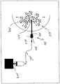
- the figure shows schematically an arrangement 1 with an applicator 100 according to the present invention.
- the applicator 100 comprises a trocar sleeve 101, in which a needle 103 is guided and in the figure has penetrated into a schematically illustrated body cavity 105. A distal end 107 lies in the body cavity 105 near the desired area of action.
- a through hole (not shown) is formed, in which the needle 103 can be tightly and slidably reciprocated.
- the distal end 107 of the needle 103 has a nozzle head 109 detachably attached to the distal end 107.
- a detachable connection between the nozzle head 109 and the distal end 107 is basically any mechanical connection conceivable.
- the nozzle head 109 is at the distal end by means of a plug connection or screw connection End 107 attached.
- nozzle head 109 has at least one nozzle opening (not shown).
- Each nozzle orifice has a dimension and / or contour that has an effect on controlling the delivery of the substance to be introduced into the body cavity.
- the substance to be introduced into the body cavity is to form an aerosol at the nozzle opening with a carrier gas.
- the dosage of the active ingredient in the aerosol can be controlled. Accordingly, a plurality of nozzle openings with different dimensions and / or contours can be provided on a nozzle head 109. The choice of the dimension and the contour of the at least one nozzle opening is therefore dependent on the substance to be introduced into the body cavity.
- Different nozzle heads 109 may differ in their number of nozzle openings and the size and / or contour of the at least one nozzle opening. In this way, the surgeon may, as needed, select a nozzle head 109 suitable for the present purpose.
- the trocar sleeve 101 has a gas port (not shown) for a gas source to inflate the body cavity 105 with a gas.
- a gas is preferably carbon dioxide.
- the trocar sleeve 101 also has a filter port (not shown).
- the trocar sleeve 101 also has a port 111 for a substance source 114 connected to a minipump 113.
- the substance source 114 is connected to the port 111 via a hose 115.
- a filter element 116 is preferably inserted in the vicinity of the terminal 111 releasably or non-detachably.
- the filter element 116 is a fine filter in order to ensure at any time the purity mentioned by the substance source 114 for the respective substance before it enters the needle 103.
- the substance to be introduced into the body cavity can be delivered via the tube 115 into the needle 103 and the at least one nozzle opening into the body cavity.
- the at least one nozzle opening or determine its dimension and / or contour determines the dosage of the substance in the aerosol.
Abstract
Description
- Applikator mit meiner Trokarhülse, einem in der Trokarhülse ausgebildeten Durchgangsloch und mit einer in Betriebsfunktion in dem Durchgangsloch der Trokarhülse geführten Nadel, an deren distalem Endbereich eine Nadeldüse ausgebildet ist.
- Ein solcher Applikator ist zum Beispiel aus
DE 10 2012 104 629 A1 und ausUS 2010/0331766 A1 bekannt, der bei einer Laparoskopie zum Einsatz kommt. Mit einem solchen Applikator wird über eine Gaszufuhr ein Hohlraum im Körper des Patienten gebildet und über die Nadeldüse ein Medikament in den Hohlraum, in die Nähe des vorgesehenen Wirkungsortes eingebracht. - In beiden Druckschriften des Standes der Technik umfasst der Applikator neben der Trokarhülse und der Nadel eine Nadelhülse, die zwischen Nadel und Trokarhülse angeordnet ist und unterschiedliche Funktionen übernimmt, z.B. Bildung von Anschlüssen, Dichtung, etc.. Eine solche Nadelhülse ist ein technisches Bauteil, dessen Verwendung in einem hochsensiblen Einsatzbereich einer besonderen Sorgfalt bedarf. So muss jedes verwendete Bauteil strenge Kriterien erfüllen, um in der Medizintechnik eingesetzt werden zu dürfen. Jede mechanische Verbindung bedarf einer großen Präzision hinsichtlich einer Übertragung von Bewegungen, Kräften etc. Die Summe der verwendeten Bauteile erhöht die Anforderungen an jedes Bauteil, damit das Endergebnis der Gesamtheit aller Bauteile diese strengen Anforderungen erfüllt.
- Es hat sich nun für den Fachmann überraschend gezeigt, dass ein Applikator der eingangs genannten Art in der Laparoskopie eingesetzt werden kann und die strengen Anforderungen erfüllt, wenn auf die Dreiteiligkeit des Standes der Technik verzichtet wird.
- Die Aufgabe der vorliegenden Erfindung ist daher, einen Applikator des Standes der Technik derart weiterzubilden, dass dieser bei gleichbleibender oder besserer Präzision technisch vereinfacht ist und die Steuerung einer Substanzmenge erleichtert.
- Die Aufgabe wird erfindungsgemäß dadurch gelöst, dass die Nadel mit ihrem Außenumfang an einem Innenumfang des Durchgangsloches dicht aber gleitfähig angeordnet ist und die Nadeldüse wenigstens eine Düsenöffnung aufweist, mit der die in die Körperhöhle einzubringende Substanz dosiert abgegeben werden kann.
- Mit dem Gegenstand der vorliegenden Erfindung kann nunmehr auf die Nadelhülse ganz verzichtet werden. Die Nadel selbst gleitet dicht sind in der Trokarhülse. Zudem weist die Nadeldüse nicht nur eine Düsenöffnung auf, wie dies im Stand der Technik der Fall ist, sondern eine zur Dosierung einer in die Körperhöhle einzubringenden Substanz geeignete Düsenöffnung. Erstmals kann also nicht nur eine Substanz in die Körperhöhle in Wirknähe eingebracht sondern dort auch dosiert abgegeben werden.
- Ein weiterer Vorteil der vorliegenden Erfindung ist, dass die Nadeldüse an dem distalen Endbereich der Nadel einen Düsenkopf bildet, der lösbar angebracht ist. Mit einem lösbaren Düsenkopf am distalen Endbereich der Nadel kann ein Austausch des Düsenkopfes in Abhängigkeit von der in die Körperhöhle einzubringenden Substanz bzw. deren Dosierung erfolgen. Es ist also nicht mehr notwendig, den ganzen Applikator auszutauschen. Vielmehr reicht es aus, nur den entsprechenden Düsenkopf am distalen Endbereich der Nadel anzubringen bzw. unter sterilen Verhältnissen auszutauschen.
- Ein weiterer Vorteil der vorliegenden Erfindung ist, dass die Düsenöffnung eine Abmessung hat, die abhängig von einer in die Körperhöhle einzubringenden Dosis der Substanz ist. Die Steuerung der Abgabe der in den Körperhohlraum einzubringenden Substanz erfolgt nicht mehr nur über ein externes Steuergerät, sondern auch über die Größe der wenigstens einen Düsenöffnung.
- Ein weiterer Vorteil der vorliegenden Erfindung ist, dass die wenigstens eine Düsenöffnung eine Kontur hat, deren Geometrie abhängig von der in die Körperhöhle einzubringenden Substanz ist. Anstelle der Abmessung oder auch zusätzlich zu der Abmessung kann die Steuerung der Abgabe der Substanz bzw. deren Dosierung auch über die Geometrie der Kontur der wenigstens einen Düsenöffnung erfolgen. So sind zum Beispiel Düsenöffnungen denkbar, die eine mehreckige, ovale und/oder runde Kontur haben.
- Weitere Vorteile der vorliegenden Erfindung ergeben sich aus den weiteren Merkmalen der Unteransprüche.
- Eine Ausführungsform der Folge Erfindung wird im Folgenden anhand der einzigen Figur näher beschrieben.
- Die Figur zeigt schematisch eine Anordnung 1 mit einem Applikator 100 gemäß der vorliegenden Erfindung.
- Der Applikator 100 umfasst eine Trokarhülse 101, in der eine Nadel 103 geführt ist und in der Figur in einen schematisch dargestellten Körperhohlraum 105 eingedrungen ist. Ein distales Ende 107 liegt in dem Körperhohlraum 105 in der Nähe des gewünschten Wirkungsbereichs. In der Trokarhülse 101 ist eine Durchgangsöffnung (nicht dargestellt) ausgebildet, in der die Nadel 103 dicht und gleitfähig hin und her bewegt werden kann.
- Das distale Ende 107 der Nadel 103 weist einen Düsenkopf 109 auf, der an dem distalen Ende 107 lösbar angebracht ist. Als lösbare Verbindung zwischen Düsenkopf 109 und distalem Ende 107 ist im Grunde jede beliebige mechanische Verbindung denkbar. Vorzugsweise ist der Düsenkopf 109 aber mithilfe einer Steckverbindung oder Schraubverbindung am distalen Ende 107 angebracht.
- Denn Düsenkopf 109 weist wenigstens eine Düsenöffnung (nicht dargestellt) auf. Jede Düsenöffnung hat eine Abmessung und/oder Kontur, die eine Auswirkung auf eine Steuerung der Abgabe der in den Körperhohlraum einzubringenden Substanz hat. Die in den Körperhohlraum einzubringende Substanz soll an der Düsenöffnung mit einem Trägergas ein Aerosol bilden. Über die Größe und die Gestalt der wenigstens einen Düsenöffnung kann die Dosierung des Wirkstoffs in dem Aerosol gesteuert werden. An einem Düsenkopf 109 können demnach mehrere Düsenöffnungen mit unterschiedlichen Abmessungen und/oder Konturen vorgesehen sein. Die Wahl der Abmessung und der Kontur der wenigstens eine Düsenöffnung ist demnach abhängig von der in den Körperhohlraum einzubringenden Substanz.
- Unterschiedliche Düsenköpfe 109 können sich in ihrer Anzahl von Düsenöffnungen und der Abmessung und/oder Kontur der wenigstens einen Düsenöffnung unterscheiden. Auf diese Weise kann der Operateur je nach Bedarf einen Düsenkopf 109 auswählen, der für den gerade vorliegenden Zweck geeignet ist.
- Die Trokarhülse 101 weist einen Gasanschluss (nicht dargestellt) für eine Gasquelle auf, um den Körperhohlraum 105 mit einem Gas aufzublasen. Ein solches Gas ist vorzugsweise Kohlendioxid. Die Trokarhülse 101 weist auch einen Filteranschluss (nicht dargestellt) auf.
- Die Trokarhülse 101 weist auch einen Anschluss 111 für eine mit einer Minipumpe 113 verbundenen Substanzquelle 114 auf. Die Substanzquelle 114 ist mit dem Anschluss 111 über einen Schlauch 115 verbunden. In den Schlauch 115 ist vorzugsweise in der Nähe des Anschlusses 111 ein Filterlement 116 lösbar oder nicht lösbar eingefügt. Ds filterlement 116 ist ein Feinfilter, um jederzeit die von der substanzquelle 114 für die jeweilige Substanz genannte Reinheit vor dem Eintritt in die Nadel 103 zu gewährleisten.
- Über eine Steuerung der Minipumpe 113 lässt sich die in die Körperhöhle einzubringende Substanz über den Schlauch 115 in die Nadel 103 und die wenigstens eine Düsenöffnung in den Körperhohlraum abgeben. Neben der Steuerung der Minipumpe 113 bestimmt die wenigstens eine Düsenöffnung, bzw. bestimmen deren Abmessung und/oder Kontur die Dosierung der Substanz im Aerosol.
-
- 1
- Anordnung
- 100
- Applikator
- 101
- Trokarhülse
- 103
- Nadel
- 105
- Körperhöhle
- 107
- distales Ende
- 109
- Düsenkopf
- 111
- Anschluss
- 113
- Minipumpe
- 114
- Substanzquelle
- 115
- Schlauch
- 116
- Filterelement
Claims (12)
- Applikator (100) mit meiner Trokarhülse (101), einem in der Trokarhülse (101) ausgebildeten Durchgangsloch und mit einer in Betriebsfunktion in dem Durchgangsloch der Trokarhülse (101) geführten Nadel (103), an deren distalem Endbereich (107) eine Nadeldüse ausgebildet ist
dadurch gekennzeichnet,
dass die Nadel (103) mit ihrem Außenumfang an einem Innenumfang des Durchgangsloches dicht aber gleitfähig angeordnet ist und die Nadeldüse wenigstens eine Düsenöffnung aufweist, mit der die in die Körperhöhle einzubringende Substanz dosiert abgegeben werden kann. - Applikator nach Anspruch 1,
dadurch gekennzeichnet,
dass die Nadeldüse an dem distalen Endbereich (107) der Nadel (103) einen Düsenkopf bildet, der lösbar angebracht ist. - Applikator nach Anspruch 2,
dadurch gekennzeichnet,
dass die wenigstens eine Düsenöffnung eine Abmessung hat, die abhängig von einer in die Körperhöhle einzubringenden Dosis der Substanz ist. - Applikator nach einem der Ansprüche 1 bis 3,
dadurch gekennzeichnet,
dass die wenigstens eine Düsenöffnung eine Kontur hat, deren Geometrie abhängig von der in die Körperhöhle einzubringenden Substanz ist. - Applikator nach einem der Ansprüche 1 bis 4,
dadurch gekennzeichnet,
dass die Trokarhülse (101) einen Gasanschluss aufweist. - Applikator nach einem der vorstehenden Ansprüche,
dadurch gekennzeichnet,
dass die Trokarhülse (101) einen Filteranschluss aufweist. - Applikator nach einem der vorstehenden Ansprüche,
dadurch gekennzeichnet,
dass an einem proximalen Endbereich der Nadel (103) ein Anschluss (111) für eine Pumpeinrichtung (113) ausgebildet ist, wobei die in die Körperhöhle (105) einzubringende Substanz von der Pumpeinrichtung (113) in die Nadel (103) und durch die Nadeldüse gepumpt werden kann. - Applikator nach Anspruch 7,
dadurch gekennzeichnet,
dass zwischen dem Anschluss (111) und der Pumpeinrichtung (113) ein Schlauch (115) angeordnet ist. - Applikator nach Anspruch 8,
dadurch gekennzeichnet,
dass in dem Schlauch (115) ein Filterelement (116) eingefügt ist. - Applikator nach einem der vorstehenden Ansprüche,
dass die in die Körperhöhle (105) einzubringende Substanz an der wenigstens einen Düsenöffnung in einem Aerosol enthalten ist. - Applikator nach einem der Ansprüche 2 bis 8,
dadurch gekennzeichnet,
dass der Düsenkopf mit dem distalen Endbereich (107) der Nadel (103) mechanisch verbunden ist. - Applikator nach Anspruch 9,
dadurch gekennzeichnet,
dass die Verbindung zwischen Düsenkopf und distalem Endbereich (107) der Nadel (103) eine Steckverbindung oder Schraubverbindung ist.
Priority Applications (3)
| Application Number | Priority Date | Filing Date | Title |
|---|---|---|---|
| EP17000123.4A EP3354213B1 (de) | 2017-01-25 | 2017-01-25 | Applikator zum einbringen einer substanz in eine körperhöhle |
| ES17000123T ES2881465T3 (es) | 2017-01-25 | 2017-01-25 | Aplicador para introducir una sustancia en una cavidad corporal |
| DK17000123.4T DK3354213T3 (da) | 2017-01-25 | 2017-01-25 | Applikator til afgivelse af en substans i et kropshulrum |
Applications Claiming Priority (1)
| Application Number | Priority Date | Filing Date | Title |
|---|---|---|---|
| EP17000123.4A EP3354213B1 (de) | 2017-01-25 | 2017-01-25 | Applikator zum einbringen einer substanz in eine körperhöhle |
Publications (2)
| Publication Number | Publication Date |
|---|---|
| EP3354213A1 true EP3354213A1 (de) | 2018-08-01 |
| EP3354213B1 EP3354213B1 (de) | 2021-05-05 |
Family
ID=57909434
Family Applications (1)
| Application Number | Title | Priority Date | Filing Date |
|---|---|---|---|
| EP17000123.4A Active EP3354213B1 (de) | 2017-01-25 | 2017-01-25 | Applikator zum einbringen einer substanz in eine körperhöhle |
Country Status (3)
| Country | Link |
|---|---|
| EP (1) | EP3354213B1 (de) |
| DK (1) | DK3354213T3 (de) |
| ES (1) | ES2881465T3 (de) |
Cited By (1)
| Publication number | Priority date | Publication date | Assignee | Title |
|---|---|---|---|---|
| DE102018121496A1 (de) * | 2018-09-04 | 2020-03-05 | Prof. Reymond & Hetzel GbR (vertretungsberechtigter Gesellschafter: Alexander Hetzel, 78667 Villingendorf) | Medizinisches Instrument zum gerichteten Einbringen einer therapeutischen Substanz in einen Hohlraum und Werkzeug dafür |
Citations (6)
| Publication number | Priority date | Publication date | Assignee | Title |
|---|---|---|---|---|
| US20100168779A1 (en) * | 2008-12-30 | 2010-07-01 | Baxter International Inc. | Tissue sealing system and apparatus |
| US20100198014A1 (en) * | 2007-06-19 | 2010-08-05 | Minimally Invasive Devices Llc | Systems and methods for optimizing and maintaining visualization of a surgical field during the use of surgical scopes |
| US20100331766A1 (en) | 2008-02-29 | 2010-12-30 | Terumo Kabushiki Kaisha | Applicator |
| US20120209166A1 (en) * | 2009-08-10 | 2012-08-16 | Aerosurgical Limited | Insufflation system |
| DE102012104629A1 (de) | 2011-05-27 | 2012-11-29 | Alexander Hetzel | Operationsvorrichtung für den laparoskopischen Einsatz |
| WO2013046710A1 (ja) * | 2011-09-30 | 2013-04-04 | 住友ベークライト株式会社 | 生体組織接着剤塗布用具およびノズルヘッド |
-
2017
- 2017-01-25 EP EP17000123.4A patent/EP3354213B1/de active Active
- 2017-01-25 DK DK17000123.4T patent/DK3354213T3/da active
- 2017-01-25 ES ES17000123T patent/ES2881465T3/es active Active
Patent Citations (6)
| Publication number | Priority date | Publication date | Assignee | Title |
|---|---|---|---|---|
| US20100198014A1 (en) * | 2007-06-19 | 2010-08-05 | Minimally Invasive Devices Llc | Systems and methods for optimizing and maintaining visualization of a surgical field during the use of surgical scopes |
| US20100331766A1 (en) | 2008-02-29 | 2010-12-30 | Terumo Kabushiki Kaisha | Applicator |
| US20100168779A1 (en) * | 2008-12-30 | 2010-07-01 | Baxter International Inc. | Tissue sealing system and apparatus |
| US20120209166A1 (en) * | 2009-08-10 | 2012-08-16 | Aerosurgical Limited | Insufflation system |
| DE102012104629A1 (de) | 2011-05-27 | 2012-11-29 | Alexander Hetzel | Operationsvorrichtung für den laparoskopischen Einsatz |
| WO2013046710A1 (ja) * | 2011-09-30 | 2013-04-04 | 住友ベークライト株式会社 | 生体組織接着剤塗布用具およびノズルヘッド |
Cited By (2)
| Publication number | Priority date | Publication date | Assignee | Title |
|---|---|---|---|---|
| DE102018121496A1 (de) * | 2018-09-04 | 2020-03-05 | Prof. Reymond & Hetzel GbR (vertretungsberechtigter Gesellschafter: Alexander Hetzel, 78667 Villingendorf) | Medizinisches Instrument zum gerichteten Einbringen einer therapeutischen Substanz in einen Hohlraum und Werkzeug dafür |
| WO2020048627A1 (de) | 2018-09-04 | 2020-03-12 | Prof. Reymond & Hetzel GbR (vertretungsberechtigter Gesellschafter: Alexander Hetzel, 78667 Villingendorf) | Medizinisches instrument zum gerichteten einbringen einer therapeutischen substanz in einen hohlraum und werkzeug dafür |
Also Published As
| Publication number | Publication date |
|---|---|
| EP3354213B1 (de) | 2021-05-05 |
| ES2881465T3 (es) | 2021-11-29 |
| DK3354213T3 (da) | 2021-07-19 |
Similar Documents
| Publication | Publication Date | Title |
|---|---|---|
| DE69838457T2 (de) | Aus zwei elementen bestehende abgabevorrichtung | |
| EP0315656B1 (de) | Infusionsgerät | |
| DE4200595C2 (de) | Baugruppe zum Infusion-Set für eine Insulinpumpe | |
| EP2627259B1 (de) | Medizinischer sprühkopf mit druckgasunterstützung | |
| DE10359249A1 (de) | Spritzenauslassspitze sowie Spritzenfluid-Austragevorrichtung und -system mit einer solchen | |
| DE10009815B4 (de) | Injektionsgerät mit einer Nadelabdeckung | |
| DE102016212579B3 (de) | Mobile Infusionspumpe | |
| DE10125261A1 (de) | Medikamentenpumpe mit bündig zu der äußeren Oberfläche abschließenden Vernähschlaufe | |
| EP0243667A2 (de) | Austragvorrichtung für Medien | |
| EP3468639B1 (de) | Vorrichtung zur abgabe eines fluids | |
| DE1491707A1 (de) | Vorrichtung fuer nasale Anwendung von Medikamenten | |
| DE102015007763A1 (de) | Einrichtung und Verfahren zum Auftragen von Klebstoff | |
| DE1213571B (de) | Vorrichtung zum Verteilen von Roentgen-kontrastmitteln oder Medikamenten im Magen-Darmtraktus | |
| EP3145417A1 (de) | Laparoskopischer sprayapplikator und adapter | |
| DE602004003168T2 (de) | Impantierbares Gerät zur Verabreichung von Medikamenten mit einer Kapillaröffnung für geringe Durchflussraten | |
| EP3354213B1 (de) | Applikator zum einbringen einer substanz in eine körperhöhle | |
| EP2898913A1 (de) | Spritze | |
| DE809698C (de) | Spritzampulle | |
| DE1800833U (de) | Geraet zum zufuehren von fluessigkeiten zum haar oder zur kopfhaut. | |
| CH703402A1 (de) | Mehr-Lumen-Verlängerung. | |
| DE19522403A1 (de) | Vorrichtung zur in-vivo-Reinigung von Körperkanälen und Gefäßen, insbesondere von Venen und Arterien | |
| DE3635698C2 (de) | Flammspritzbrenner zur Herstellung von Oberflächenschichten auf Werkstücken | |
| DE102020123589A1 (de) | Dreikammer-Kapsel-Applikationssystem für medizinische Anwendungen | |
| EP2926740A1 (de) | Medizinische Einrichtung zur Ausbildung eines implantierbaren Rings | |
| DE69828927T2 (de) | Vorrichtung zur Abgabe von Zweikomponentenklebmasse mit einem statischen Mischer |
Legal Events
| Date | Code | Title | Description |
|---|---|---|---|
| STAA | Information on the status of an ep patent application or granted ep patent |
Free format text: STATUS: UNKNOWN |
|
| PUAI | Public reference made under article 153(3) epc to a published international application that has entered the european phase |
Free format text: ORIGINAL CODE: 0009012 |
|
| STAA | Information on the status of an ep patent application or granted ep patent |
Free format text: STATUS: THE APPLICATION HAS BEEN PUBLISHED |
|
| AK | Designated contracting states |
Kind code of ref document: A1 Designated state(s): AL AT BE BG CH CY CZ DE DK EE ES FI FR GB GR HR HU IE IS IT LI LT LU LV MC MK MT NL NO PL PT RO RS SE SI SK SM TR |
|
| AX | Request for extension of the european patent |
Extension state: BA ME |
|
| STAA | Information on the status of an ep patent application or granted ep patent |
Free format text: STATUS: REQUEST FOR EXAMINATION WAS MADE |
|
| 17P | Request for examination filed |
Effective date: 20190130 |
|
| RBV | Designated contracting states (corrected) |
Designated state(s): AL AT BE BG CH CY CZ DE DK EE ES FI FR GB GR HR HU IE IS IT LI LT LU LV MC MK MT NL NO PL PT RO RS SE SI SK SM TR |
|
| REG | Reference to a national code |
Ref country code: DE Ref legal event code: R079 Ref document number: 502017010242 Country of ref document: DE Free format text: PREVIOUS MAIN CLASS: A61B0017340000 Ipc: A61M0011000000 |
|
| GRAP | Despatch of communication of intention to grant a patent |
Free format text: ORIGINAL CODE: EPIDOSNIGR1 |
|
| STAA | Information on the status of an ep patent application or granted ep patent |
Free format text: STATUS: GRANT OF PATENT IS INTENDED |
|
| RIC1 | Information provided on ipc code assigned before grant |
Ipc: A61M 11/00 20060101AFI20201112BHEP Ipc: A61M 11/02 20060101ALI20201112BHEP Ipc: A61M 13/00 20060101ALN20201112BHEP Ipc: A61B 17/34 20060101ALI20201112BHEP |
|
| INTG | Intention to grant announced |
Effective date: 20201204 |
|
| RIC1 | Information provided on ipc code assigned before grant |
Ipc: A61B 17/34 20060101ALI20201123BHEP Ipc: A61M 13/00 20060101ALN20201123BHEP Ipc: A61M 11/00 20060101AFI20201123BHEP Ipc: A61M 11/02 20060101ALI20201123BHEP |
|
| GRAS | Grant fee paid |
Free format text: ORIGINAL CODE: EPIDOSNIGR3 |
|
| GRAA | (expected) grant |
Free format text: ORIGINAL CODE: 0009210 |
|
| STAA | Information on the status of an ep patent application or granted ep patent |
Free format text: STATUS: THE PATENT HAS BEEN GRANTED |
|
| AK | Designated contracting states |
Kind code of ref document: B1 Designated state(s): AL AT BE BG CH CY CZ DE DK EE ES FI FR GB GR HR HU IE IS IT LI LT LU LV MC MK MT NL NO PL PT RO RS SE SI SK SM TR |
|
| REG | Reference to a national code |
Ref country code: GB Ref legal event code: FG4D Free format text: NOT ENGLISH |
|
| REG | Reference to a national code |
Ref country code: CH Ref legal event code: EP |
|
| REG | Reference to a national code |
Ref country code: AT Ref legal event code: REF Ref document number: 1389014 Country of ref document: AT Kind code of ref document: T Effective date: 20210515 |
|
| REG | Reference to a national code |
Ref country code: IE Ref legal event code: FG4D Free format text: LANGUAGE OF EP DOCUMENT: GERMAN |
|
| REG | Reference to a national code |
Ref country code: DE Ref legal event code: R096 Ref document number: 502017010242 Country of ref document: DE |
|
| REG | Reference to a national code |
Ref country code: DK Ref legal event code: T3 Effective date: 20210712 |
|
| REG | Reference to a national code |
Ref country code: NL Ref legal event code: FP |
|
| REG | Reference to a national code |
Ref country code: LT Ref legal event code: MG9D |
|
| PG25 | Lapsed in a contracting state [announced via postgrant information from national office to epo] |
Ref country code: HR Free format text: LAPSE BECAUSE OF FAILURE TO SUBMIT A TRANSLATION OF THE DESCRIPTION OR TO PAY THE FEE WITHIN THE PRESCRIBED TIME-LIMIT Effective date: 20210505 Ref country code: BG Free format text: LAPSE BECAUSE OF FAILURE TO SUBMIT A TRANSLATION OF THE DESCRIPTION OR TO PAY THE FEE WITHIN THE PRESCRIBED TIME-LIMIT Effective date: 20210805 Ref country code: LT Free format text: LAPSE BECAUSE OF FAILURE TO SUBMIT A TRANSLATION OF THE DESCRIPTION OR TO PAY THE FEE WITHIN THE PRESCRIBED TIME-LIMIT Effective date: 20210505 Ref country code: FI Free format text: LAPSE BECAUSE OF FAILURE TO SUBMIT A TRANSLATION OF THE DESCRIPTION OR TO PAY THE FEE WITHIN THE PRESCRIBED TIME-LIMIT Effective date: 20210505 |
|
| REG | Reference to a national code |
Ref country code: ES Ref legal event code: FG2A Ref document number: 2881465 Country of ref document: ES Kind code of ref document: T3 Effective date: 20211129 |
|
| PG25 | Lapsed in a contracting state [announced via postgrant information from national office to epo] |
Ref country code: RS Free format text: LAPSE BECAUSE OF FAILURE TO SUBMIT A TRANSLATION OF THE DESCRIPTION OR TO PAY THE FEE WITHIN THE PRESCRIBED TIME-LIMIT Effective date: 20210505 Ref country code: SE Free format text: LAPSE BECAUSE OF FAILURE TO SUBMIT A TRANSLATION OF THE DESCRIPTION OR TO PAY THE FEE WITHIN THE PRESCRIBED TIME-LIMIT Effective date: 20210505 Ref country code: NO Free format text: LAPSE BECAUSE OF FAILURE TO SUBMIT A TRANSLATION OF THE DESCRIPTION OR TO PAY THE FEE WITHIN THE PRESCRIBED TIME-LIMIT Effective date: 20210805 Ref country code: PT Free format text: LAPSE BECAUSE OF FAILURE TO SUBMIT A TRANSLATION OF THE DESCRIPTION OR TO PAY THE FEE WITHIN THE PRESCRIBED TIME-LIMIT Effective date: 20210906 Ref country code: PL Free format text: LAPSE BECAUSE OF FAILURE TO SUBMIT A TRANSLATION OF THE DESCRIPTION OR TO PAY THE FEE WITHIN THE PRESCRIBED TIME-LIMIT Effective date: 20210505 Ref country code: IS Free format text: LAPSE BECAUSE OF FAILURE TO SUBMIT A TRANSLATION OF THE DESCRIPTION OR TO PAY THE FEE WITHIN THE PRESCRIBED TIME-LIMIT Effective date: 20210905 Ref country code: GR Free format text: LAPSE BECAUSE OF FAILURE TO SUBMIT A TRANSLATION OF THE DESCRIPTION OR TO PAY THE FEE WITHIN THE PRESCRIBED TIME-LIMIT Effective date: 20210806 Ref country code: LV Free format text: LAPSE BECAUSE OF FAILURE TO SUBMIT A TRANSLATION OF THE DESCRIPTION OR TO PAY THE FEE WITHIN THE PRESCRIBED TIME-LIMIT Effective date: 20210505 |
|
| PG25 | Lapsed in a contracting state [announced via postgrant information from national office to epo] |
Ref country code: SM Free format text: LAPSE BECAUSE OF FAILURE TO SUBMIT A TRANSLATION OF THE DESCRIPTION OR TO PAY THE FEE WITHIN THE PRESCRIBED TIME-LIMIT Effective date: 20210505 Ref country code: SK Free format text: LAPSE BECAUSE OF FAILURE TO SUBMIT A TRANSLATION OF THE DESCRIPTION OR TO PAY THE FEE WITHIN THE PRESCRIBED TIME-LIMIT Effective date: 20210505 Ref country code: EE Free format text: LAPSE BECAUSE OF FAILURE TO SUBMIT A TRANSLATION OF THE DESCRIPTION OR TO PAY THE FEE WITHIN THE PRESCRIBED TIME-LIMIT Effective date: 20210505 Ref country code: CZ Free format text: LAPSE BECAUSE OF FAILURE TO SUBMIT A TRANSLATION OF THE DESCRIPTION OR TO PAY THE FEE WITHIN THE PRESCRIBED TIME-LIMIT Effective date: 20210505 Ref country code: RO Free format text: LAPSE BECAUSE OF FAILURE TO SUBMIT A TRANSLATION OF THE DESCRIPTION OR TO PAY THE FEE WITHIN THE PRESCRIBED TIME-LIMIT Effective date: 20210505 |
|
| REG | Reference to a national code |
Ref country code: DE Ref legal event code: R097 Ref document number: 502017010242 Country of ref document: DE |
|
| PLBE | No opposition filed within time limit |
Free format text: ORIGINAL CODE: 0009261 |
|
| STAA | Information on the status of an ep patent application or granted ep patent |
Free format text: STATUS: NO OPPOSITION FILED WITHIN TIME LIMIT |
|
| PGFP | Annual fee paid to national office [announced via postgrant information from national office to epo] |
Ref country code: LU Payment date: 20220120 Year of fee payment: 6 |
|
| 26N | No opposition filed |
Effective date: 20220208 |
|
| PGFP | Annual fee paid to national office [announced via postgrant information from national office to epo] |
Ref country code: IE Payment date: 20220125 Year of fee payment: 6 Ref country code: GB Payment date: 20220125 Year of fee payment: 6 Ref country code: DK Payment date: 20220121 Year of fee payment: 6 Ref country code: CH Payment date: 20220125 Year of fee payment: 6 Ref country code: AT Payment date: 20220119 Year of fee payment: 6 |
|
| PG25 | Lapsed in a contracting state [announced via postgrant information from national office to epo] |
Ref country code: IS Free format text: LAPSE BECAUSE OF FAILURE TO SUBMIT A TRANSLATION OF THE DESCRIPTION OR TO PAY THE FEE WITHIN THE PRESCRIBED TIME-LIMIT Effective date: 20210905 Ref country code: AL Free format text: LAPSE BECAUSE OF FAILURE TO SUBMIT A TRANSLATION OF THE DESCRIPTION OR TO PAY THE FEE WITHIN THE PRESCRIBED TIME-LIMIT Effective date: 20210505 |
|
| PGFP | Annual fee paid to national office [announced via postgrant information from national office to epo] |
Ref country code: NL Payment date: 20220120 Year of fee payment: 6 Ref country code: MC Payment date: 20220120 Year of fee payment: 6 Ref country code: IT Payment date: 20220124 Year of fee payment: 6 Ref country code: FR Payment date: 20220120 Year of fee payment: 6 Ref country code: ES Payment date: 20220216 Year of fee payment: 6 Ref country code: BE Payment date: 20220120 Year of fee payment: 6 |
|
| PGFP | Annual fee paid to national office [announced via postgrant information from national office to epo] |
Ref country code: TR Payment date: 20230216 Year of fee payment: 7 |
|
| REG | Reference to a national code |
Ref country code: DK Ref legal event code: EBP Effective date: 20230131 |
|
| REG | Reference to a national code |
Ref country code: CH Ref legal event code: PL |
|
| REG | Reference to a national code |
Ref country code: NL Ref legal event code: MM Effective date: 20230201 |
|
| REG | Reference to a national code |
Ref country code: AT Ref legal event code: MM01 Ref document number: 1389014 Country of ref document: AT Kind code of ref document: T Effective date: 20230125 |
|
| GBPC | Gb: european patent ceased through non-payment of renewal fee |
Effective date: 20230125 |
|
| PG25 | Lapsed in a contracting state [announced via postgrant information from national office to epo] |
Ref country code: LU Free format text: LAPSE BECAUSE OF NON-PAYMENT OF DUE FEES Effective date: 20230125 |
|
| REG | Reference to a national code |
Ref country code: BE Ref legal event code: MM Effective date: 20230131 |
|
| PG25 | Lapsed in a contracting state [announced via postgrant information from national office to epo] |
Ref country code: NL Free format text: LAPSE BECAUSE OF NON-PAYMENT OF DUE FEES Effective date: 20230201 Ref country code: LI Free format text: LAPSE BECAUSE OF NON-PAYMENT OF DUE FEES Effective date: 20230131 Ref country code: GB Free format text: LAPSE BECAUSE OF NON-PAYMENT OF DUE FEES Effective date: 20230125 Ref country code: CH Free format text: LAPSE BECAUSE OF NON-PAYMENT OF DUE FEES Effective date: 20230131 Ref country code: AT Free format text: LAPSE BECAUSE OF NON-PAYMENT OF DUE FEES Effective date: 20230125 |
|
| PG25 | Lapsed in a contracting state [announced via postgrant information from national office to epo] |
Ref country code: FR Free format text: LAPSE BECAUSE OF NON-PAYMENT OF DUE FEES Effective date: 20230131 Ref country code: BE Free format text: LAPSE BECAUSE OF NON-PAYMENT OF DUE FEES Effective date: 20230131 |
|
| PGFP | Annual fee paid to national office [announced via postgrant information from national office to epo] |
Ref country code: DE Payment date: 20230727 Year of fee payment: 7 |
|
| PG25 | Lapsed in a contracting state [announced via postgrant information from national office to epo] |
Ref country code: IT Free format text: LAPSE BECAUSE OF NON-PAYMENT OF DUE FEES Effective date: 20230125 Ref country code: IE Free format text: LAPSE BECAUSE OF NON-PAYMENT OF DUE FEES Effective date: 20230125 Ref country code: DK Free format text: LAPSE BECAUSE OF NON-PAYMENT OF DUE FEES Effective date: 20230131 |
|
| PG25 | Lapsed in a contracting state [announced via postgrant information from national office to epo] |
Ref country code: HU Free format text: LAPSE BECAUSE OF FAILURE TO SUBMIT A TRANSLATION OF THE DESCRIPTION OR TO PAY THE FEE WITHIN THE PRESCRIBED TIME-LIMIT; INVALID AB INITIO Effective date: 20170125 |
|
| REG | Reference to a national code |
Ref country code: ES Ref legal event code: FD2A Effective date: 20240402 |
|
| PG25 | Lapsed in a contracting state [announced via postgrant information from national office to epo] |
Ref country code: ES Free format text: LAPSE BECAUSE OF NON-PAYMENT OF DUE FEES Effective date: 20230126 |
|
| PG25 | Lapsed in a contracting state [announced via postgrant information from national office to epo] |
Ref country code: MK Free format text: LAPSE BECAUSE OF FAILURE TO SUBMIT A TRANSLATION OF THE DESCRIPTION OR TO PAY THE FEE WITHIN THE PRESCRIBED TIME-LIMIT Effective date: 20210505 Ref country code: ES Free format text: LAPSE BECAUSE OF NON-PAYMENT OF DUE FEES Effective date: 20230126 Ref country code: CY Free format text: LAPSE BECAUSE OF FAILURE TO SUBMIT A TRANSLATION OF THE DESCRIPTION OR TO PAY THE FEE WITHIN THE PRESCRIBED TIME-LIMIT Effective date: 20210505 |