EP3351755A1 - Système d'huile avec filtre à huile résistant au bouchage - Google Patents
Système d'huile avec filtre à huile résistant au bouchage Download PDFInfo
- Publication number
- EP3351755A1 EP3351755A1 EP18152048.7A EP18152048A EP3351755A1 EP 3351755 A1 EP3351755 A1 EP 3351755A1 EP 18152048 A EP18152048 A EP 18152048A EP 3351755 A1 EP3351755 A1 EP 3351755A1
- Authority
- EP
- European Patent Office
- Prior art keywords
- oil
- filter
- pump
- pressure
- oil pump
- Prior art date
- Legal status (The legal status is an assumption and is not a legal conclusion. Google has not performed a legal analysis and makes no representation as to the accuracy of the status listed.)
- Granted
Links
- 238000006073 displacement reaction Methods 0.000 claims abstract description 48
- 230000007246 mechanism Effects 0.000 claims abstract description 27
- 238000001914 filtration Methods 0.000 claims abstract description 10
- 239000000356 contaminant Substances 0.000 claims description 15
- 239000007787 solid Substances 0.000 claims description 7
- 238000005461 lubrication Methods 0.000 claims 1
- 239000003921 oil Substances 0.000 description 456
- 230000001965 increasing effect Effects 0.000 description 11
- 239000000463 material Substances 0.000 description 8
- 230000001105 regulatory effect Effects 0.000 description 8
- 238000009434 installation Methods 0.000 description 7
- 238000004891 communication Methods 0.000 description 6
- 230000006835 compression Effects 0.000 description 6
- 238000007906 compression Methods 0.000 description 6
- 239000012530 fluid Substances 0.000 description 6
- 239000010687 lubricating oil Substances 0.000 description 5
- 230000008859 change Effects 0.000 description 3
- 238000005553 drilling Methods 0.000 description 3
- 238000005086 pumping Methods 0.000 description 3
- 238000005266 casting Methods 0.000 description 2
- 238000010586 diagram Methods 0.000 description 2
- 230000000694 effects Effects 0.000 description 2
- 230000001788 irregular Effects 0.000 description 2
- 238000004519 manufacturing process Methods 0.000 description 2
- 239000010705 motor oil Substances 0.000 description 2
- 230000009467 reduction Effects 0.000 description 2
- 230000008844 regulatory mechanism Effects 0.000 description 2
- 238000009825 accumulation Methods 0.000 description 1
- 230000000903 blocking effect Effects 0.000 description 1
- 230000015556 catabolic process Effects 0.000 description 1
- 238000011109 contamination Methods 0.000 description 1
- 230000002596 correlated effect Effects 0.000 description 1
- 238000006731 degradation reaction Methods 0.000 description 1
- 230000001419 dependent effect Effects 0.000 description 1
- 238000005516 engineering process Methods 0.000 description 1
- 239000000446 fuel Substances 0.000 description 1
- 238000010348 incorporation Methods 0.000 description 1
- 230000001939 inductive effect Effects 0.000 description 1
- 238000003754 machining Methods 0.000 description 1
- 239000002184 metal Substances 0.000 description 1
- 238000000034 method Methods 0.000 description 1
- 230000007935 neutral effect Effects 0.000 description 1
Images


Classifications
-
- F—MECHANICAL ENGINEERING; LIGHTING; HEATING; WEAPONS; BLASTING
- F01—MACHINES OR ENGINES IN GENERAL; ENGINE PLANTS IN GENERAL; STEAM ENGINES
- F01M—LUBRICATING OF MACHINES OR ENGINES IN GENERAL; LUBRICATING INTERNAL COMBUSTION ENGINES; CRANKCASE VENTILATING
- F01M1/00—Pressure lubrication
- F01M1/02—Pressure lubrication using lubricating pumps
-
- F—MECHANICAL ENGINEERING; LIGHTING; HEATING; WEAPONS; BLASTING
- F01—MACHINES OR ENGINES IN GENERAL; ENGINE PLANTS IN GENERAL; STEAM ENGINES
- F01M—LUBRICATING OF MACHINES OR ENGINES IN GENERAL; LUBRICATING INTERNAL COMBUSTION ENGINES; CRANKCASE VENTILATING
- F01M1/00—Pressure lubrication
- F01M1/10—Lubricating systems characterised by the provision therein of lubricant venting or purifying means, e.g. of filters
-
- B—PERFORMING OPERATIONS; TRANSPORTING
- B01—PHYSICAL OR CHEMICAL PROCESSES OR APPARATUS IN GENERAL
- B01D—SEPARATION
- B01D35/00—Filtering devices having features not specifically covered by groups B01D24/00 - B01D33/00, or for applications not specifically covered by groups B01D24/00 - B01D33/00; Auxiliary devices for filtration; Filter housing constructions
- B01D35/005—Filters specially adapted for use in internal-combustion engine lubrication or fuel systems
-
- B—PERFORMING OPERATIONS; TRANSPORTING
- B01—PHYSICAL OR CHEMICAL PROCESSES OR APPARATUS IN GENERAL
- B01D—SEPARATION
- B01D35/00—Filtering devices having features not specifically covered by groups B01D24/00 - B01D33/00, or for applications not specifically covered by groups B01D24/00 - B01D33/00; Auxiliary devices for filtration; Filter housing constructions
- B01D35/30—Filter housing constructions
-
- F—MECHANICAL ENGINEERING; LIGHTING; HEATING; WEAPONS; BLASTING
- F01—MACHINES OR ENGINES IN GENERAL; ENGINE PLANTS IN GENERAL; STEAM ENGINES
- F01M—LUBRICATING OF MACHINES OR ENGINES IN GENERAL; LUBRICATING INTERNAL COMBUSTION ENGINES; CRANKCASE VENTILATING
- F01M1/00—Pressure lubrication
- F01M1/16—Controlling lubricant pressure or quantity
-
- F—MECHANICAL ENGINEERING; LIGHTING; HEATING; WEAPONS; BLASTING
- F01—MACHINES OR ENGINES IN GENERAL; ENGINE PLANTS IN GENERAL; STEAM ENGINES
- F01M—LUBRICATING OF MACHINES OR ENGINES IN GENERAL; LUBRICATING INTERNAL COMBUSTION ENGINES; CRANKCASE VENTILATING
- F01M11/00—Component parts, details or accessories, not provided for in, or of interest apart from, groups F01M1/00 - F01M9/00
- F01M11/03—Mounting or connecting of lubricant purifying means relative to the machine or engine; Details of lubricant purifying means
-
- F—MECHANICAL ENGINEERING; LIGHTING; HEATING; WEAPONS; BLASTING
- F16—ENGINEERING ELEMENTS AND UNITS; GENERAL MEASURES FOR PRODUCING AND MAINTAINING EFFECTIVE FUNCTIONING OF MACHINES OR INSTALLATIONS; THERMAL INSULATION IN GENERAL
- F16N—LUBRICATING
- F16N13/00—Lubricating-pumps
- F16N13/02—Lubricating-pumps with reciprocating piston
- F16N13/04—Adjustable reciprocating pumps
-
- F—MECHANICAL ENGINEERING; LIGHTING; HEATING; WEAPONS; BLASTING
- F16—ENGINEERING ELEMENTS AND UNITS; GENERAL MEASURES FOR PRODUCING AND MAINTAINING EFFECTIVE FUNCTIONING OF MACHINES OR INSTALLATIONS; THERMAL INSULATION IN GENERAL
- F16N—LUBRICATING
- F16N13/00—Lubricating-pumps
- F16N13/02—Lubricating-pumps with reciprocating piston
- F16N13/06—Actuation of lubricating-pumps
- F16N13/10—Actuation of lubricating-pumps with mechanical drive
-
- F—MECHANICAL ENGINEERING; LIGHTING; HEATING; WEAPONS; BLASTING
- F16—ENGINEERING ELEMENTS AND UNITS; GENERAL MEASURES FOR PRODUCING AND MAINTAINING EFFECTIVE FUNCTIONING OF MACHINES OR INSTALLATIONS; THERMAL INSULATION IN GENERAL
- F16N—LUBRICATING
- F16N39/00—Arrangements for conditioning of lubricants in the lubricating system
- F16N39/06—Arrangements for conditioning of lubricants in the lubricating system by filtration
-
- B—PERFORMING OPERATIONS; TRANSPORTING
- B01—PHYSICAL OR CHEMICAL PROCESSES OR APPARATUS IN GENERAL
- B01D—SEPARATION
- B01D2201/00—Details relating to filtering apparatus
- B01D2201/30—Filter housing constructions
- B01D2201/301—Details of removable closures, lids, caps, filter heads
- B01D2201/302—Details of removable closures, lids, caps, filter heads having inlet or outlet ports
-
- B—PERFORMING OPERATIONS; TRANSPORTING
- B01—PHYSICAL OR CHEMICAL PROCESSES OR APPARATUS IN GENERAL
- B01D—SEPARATION
- B01D2201/00—Details relating to filtering apparatus
- B01D2201/60—Shape of non-cylindrical filtering elements
- B01D2201/605—Square or rectangular
-
- F—MECHANICAL ENGINEERING; LIGHTING; HEATING; WEAPONS; BLASTING
- F01—MACHINES OR ENGINES IN GENERAL; ENGINE PLANTS IN GENERAL; STEAM ENGINES
- F01M—LUBRICATING OF MACHINES OR ENGINES IN GENERAL; LUBRICATING INTERNAL COMBUSTION ENGINES; CRANKCASE VENTILATING
- F01M1/00—Pressure lubrication
- F01M1/02—Pressure lubrication using lubricating pumps
- F01M2001/0207—Pressure lubrication using lubricating pumps characterised by the type of pump
- F01M2001/023—Piston pumps
-
- F—MECHANICAL ENGINEERING; LIGHTING; HEATING; WEAPONS; BLASTING
- F01—MACHINES OR ENGINES IN GENERAL; ENGINE PLANTS IN GENERAL; STEAM ENGINES
- F01M—LUBRICATING OF MACHINES OR ENGINES IN GENERAL; LUBRICATING INTERNAL COMBUSTION ENGINES; CRANKCASE VENTILATING
- F01M1/00—Pressure lubrication
- F01M1/02—Pressure lubrication using lubricating pumps
- F01M2001/0207—Pressure lubrication using lubricating pumps characterised by the type of pump
- F01M2001/0238—Rotary pumps
-
- F—MECHANICAL ENGINEERING; LIGHTING; HEATING; WEAPONS; BLASTING
- F01—MACHINES OR ENGINES IN GENERAL; ENGINE PLANTS IN GENERAL; STEAM ENGINES
- F01M—LUBRICATING OF MACHINES OR ENGINES IN GENERAL; LUBRICATING INTERNAL COMBUSTION ENGINES; CRANKCASE VENTILATING
- F01M1/00—Pressure lubrication
- F01M1/02—Pressure lubrication using lubricating pumps
- F01M2001/0207—Pressure lubrication using lubricating pumps characterised by the type of pump
- F01M2001/0246—Adjustable pumps
-
- F—MECHANICAL ENGINEERING; LIGHTING; HEATING; WEAPONS; BLASTING
- F01—MACHINES OR ENGINES IN GENERAL; ENGINE PLANTS IN GENERAL; STEAM ENGINES
- F01M—LUBRICATING OF MACHINES OR ENGINES IN GENERAL; LUBRICATING INTERNAL COMBUSTION ENGINES; CRANKCASE VENTILATING
- F01M1/00—Pressure lubrication
- F01M1/10—Lubricating systems characterised by the provision therein of lubricant venting or purifying means, e.g. of filters
- F01M2001/105—Lubricating systems characterised by the provision therein of lubricant venting or purifying means, e.g. of filters characterised by the layout of the purification arrangements
- F01M2001/1078—Lubricating systems characterised by the provision therein of lubricant venting or purifying means, e.g. of filters characterised by the layout of the purification arrangements comprising an oil pick-up tube to oil pump, e.g. strainer
Definitions
- variable displacement oil pump may comprise a pressure regulation mechanism configured to vary the displacement of the oil pump in order to regulate the pressure of oil output by the pump. It is desirable to ensure that the pressure regulation mechanism of the pump continues operating effectively throughout the life of the oil pump to ensure that the oil pump continues to supply oil to the components.
- Oil filters remove harmful contaminants from oil to protect components of the oil system from wear or degradation. Oil filters may become clogged by these contaminants and not allow oil to pass. Oil may not be able to flow through a filter if an alternative path around clogging particulates is not available.
- a conventional filter is a circular filter within a circular oil passage. Particulates may build up on the filter blocking the entire passage and preventing flow of oil.
- a system for a variable displacement oil pump for a motor vehicle comprising: a mechanism for adjusting the displacement of the pump, the mechanism including an oil port formed in an internal wall of the pump, the oil port having a filter wherein a filter surface area of the filter is spaced apart from an inlet of the oil port, wherein the filter surface area is larger than an area of the inlet, wherein the filter is substantially prism shaped and wherein the filter surface area forms an outer surface of the prism.
- the larger surface area of the filter surface area and the prism shape of the filter allow for oil to pass around possible particulates and into the inlet.
- an oil pump e.g. a variable displacement oil pump, for a motor vehicle the oil pump comprising: a mechanism for adjusting the displacement of the pump, the mechanism comprising an oil port formed in an internal wall of the pump, the oil port having a filter wherein a filter element of the filter is spaced apart from an opening of the oil port and wherein the filter element is larger than an area of the opening.
- the filtering surface (comprising an area of the filter element through which the oil passes) may be larger than the area of the opening.
- a rotary machine for a motor vehicle comprising an oil port formed in an internal wall of the rotary machine, the oil port having a filter, wherein an oil admitting area of a filter element of the filter is larger than an area of the opening.
- the filter element may be spaced apart from an opening forming the oil port.
- the rotary machine may comprise a pump such as an engine oil pump. Where the pump is a variable displacement pump, the oil port may admit oil to the mechanism that varies the displacement of the pump.
- the mechanism may, for example, comprise an internal valve.
- a rotary machine for a motor vehicle comprising an oil port formed in an internal wall of the rotary machine, the oil port having a filter, wherein a filter element of the filter is spaced apart from an opening forming the oil port.
- An oil admitting area of the filter element may be larger than an area of the opening.
- the rotary machine may comprise a pump such as an engine oil pump. Where the pump is a variable displacement pump, the oil port may admit oil to the mechanism that varies the displacement of the pump.
- the mechanism may, for example, comprise an internal valve.
- the filter may be arranged such that oil may pass through the filter element prior to flowing through the oil port.
- the filter element may comprise a mesh, e.g. a metallic mesh. Additionally or alternatively, the filter element may comprise felt or paper and/or be formed of any other material capable of filtering the oil.
- the internal wall may be defined in a housing of the oil pump.
- the oil port may be arranged such that a portion of the oil pumped by the oil pump passes through the oil port, e.g. to the mechanism for adjusting the displacement of the pump.
- the filter may be supported by the oil pump away from the opening of the oil port, e.g. by the housing of the oil pump. In some arrangements, the filter may be supported by the internal wall.
- the filter may be press fit, glued, threaded and/or clipped to the oil pump, e.g. to the housing and/or the internal wall.
- the filter may be substantially prism shaped.
- the filter may form a regular prism, such as a square prism or a cylinder, or an irregular prism.
- the shape of the filter may define a conical prism.
- the filter element may form an outer surface of the prism.
- the filter may be arranged such that oil does not pass though the longitudinal slot prior to passing through the filter element.
- oil may pass though the filter element of the filter prior to passing through the longitudinal slot.
- the filter may be arranged, such that both edges of the longitudinal slot contact a wall of the housing, e.g. the internal wall.
- the filter may be arranged such that a central/longitudinal axis of the filter, e.g. of the prismatic shape defined by the oil filter, is at an angle relative to a flow path defined by the oil port.
- the oil filter may be arranged such that the central axis of the oil filter is at substantially 90 degrees to the flow path defined by the oil port.
- the filter may be resilient.
- the filter may be configured to expand by virtue of its resilience in order to engage one or more walls of the pump, e.g. the internal wall and/or one or more other walls of the pump, such that the filter is supported within the pump.
- the filter may expand during installation of the filter.
- the filter may be compressed prior to installation into the pump and may expand during installation in order to engage the walls of the pump. During expansion of the filter, the width of the longitudinal slot formed in the outer surface of the filter may increase.
- the oil port may be configured to deliver oil to the mechanism for adjusting the displacement of the pump of the oil pump, in order to regulate the pressure of oil supplied by the pump.
- the spool valve may comprise a pressure regulation chamber and a spool, movable within the pressure regulation chamber. Oil passing though the oil port may flow into the pressure regulation chamber.
- the spool valve may further comprise a pressure regulation outlet configured to allow oil to flow out of the pressure regulation chamber. The position of the spool within the pressure chamber may be varied according to an outlet pressure of the oil pump, in order to vary a flow area of the pressure regulation outlet.
- the spool valve may further comprise a low pressure set input.
- the spool valve may be configured to receive oil via the low pressure set input in order to adjust the position of the spool within the pressure regulation chamber and thereby adjust the operation of the oil pump, e.g. to adjust the outlet pressure of the oil pump.
- Providing oil to the low pressure set input may adjust a balance of forces acting on the spool, which may affect the regulated outlet pressure of the oil pump.
- a lubricating oil system for an engine of a motor vehicle may comprise: an oil sump; the above-mentioned oil pump, wherein the oil pump is configured to draw oil from the oil sump into an inlet of the oil pump and pump the oil out of an outlet of the oil pump; and an oil gallery configured to receive pressurised oil from the outlet of the oil pump.
- the oil gallery may be configured to deliver the pressurised oil to one or more pressure lubricated components of the engine.
- FIGS. 1-5 show example configurations with relative positioning of the various components. If shown directly contacting each other, or directly coupled, then such elements may be referred to as directly contacting or directly coupled, respectively, at least in one example. Similarly, elements shown contiguous or adjacent to one another may be contiguous or adjacent to each other, respectively, at least in one example. As an example, components laying in face-sharing contact with each other may be referred to as in face-sharing contact. As another example, elements positioned apart from each other with only a space there-between and no other components may be referred to as such, in at least one example. As yet another example, elements shown above/below one another, at opposite sides to one another, or to the left/right of one another may be referred to as such, relative to one another.
- topmost element or point of element may be referred to as a "top” of the component and a bottommost element or point of the element may be referred to as a "bottom” of the component, in at least one example.
- top/bottom, upper/lower, above/below may be relative to a vertical axis of the figures and used to describe positioning of elements of the figures relative to one another.
- elements shown above other elements are positioned vertically above the other elements, in one example.
- shapes of the elements depicted within the figures may be referred to as having those shapes (e.g., such as being circular, straight, planar, curved, rounded, chamfered, angled, or the like).
- elements shown intersecting one another may be referred to as intersecting elements or intersecting one another, in at least one example.
- an element shown within another element or shown outside of another element may be referred as such, in one example.
- An oil pick-up 18 is arranged within the oil sump 12 and configured to allow the oil to be drawn into an inlet of the oil pump.
- the oil pick-up 18 may comprise a mesh, generally a relatively course mesh, configured to prevent debris within the oil sump being drawn into the pump 100.
- the oil pump 100 may be a variable displacement pump.
- the oil pump 100 may comprise a displacement control mechanism configured to adjust the displacement of the pump according to an outlet pressure of the pump in order to regulate the outlet pressure.
- a bulk flow of oil pumped by the pump 100 leaves the pump via an outlet.
- the oil leaving the pump may be delivered to a main oil gallery 20 of the engine 2.
- the main oil gallery 20 supplies oil to each of the pressure lubricated components 50 of the engine.
- a third inlet 176 may be in fluid communication with the main oil gallery 20. Hence the third inlet 176 may receive oil at a pressure substantially equal to the outlet pressure of the oil pump 100.
- a second inlet 174 may be in fluid communication with a pressure control valve 24. The pressure control valve 24 may provide pressurized oil to the second inlet 176 when it is desirable to reduce the pressure of oil being supplied by the oil pump, as described below.
- the mesh provided at the oil pick-up 18 may have a large mesh size and is intended to prevent large pieces of debris from being drawn into the pump. Before the oil is circulated around the engine, it is desirable for the oil to be filtered to remove smaller solid contaminants. These contaminants might otherwise build up within and damage the pressure lubricated components 50 of the engine 2.
- the oil system 10 may further comprise an oil filter 22.
- the oil leaving the outlet of the pump may be passed through the oil filter 22 before reaching the main oil gallery 20.
- Oil filter 22 removes potentially damaging or wear inducing solid contaminants present within the oil leaving the oil pump 100.
- the oil pick-up 18 is provided with a coarse mesh configured to prevent large pieces of debris from entering the oil pump 100.
- the oil filter 22 is provided to remove smaller pieces of debris and solid contaminants from the oil that passed through the pick-up mesh.
- oil passing through a port such as oil port 114 into the first pressure regulation chamber may not have been passed through the oil filter 22 since leaving the oil sump 12. Any solid contaminants present within the oil passing through the port 114 may settle into pumping or valve components which may be degraded or rendered inoperable by a buildup of contaminants. Therefore, filtering oil before it enters these components is desirable.
- an oil pump 100 comprises a housing 101 defining an inlet chamber 102 and an outlet chamber 104, and a pump portion 120. Oil entering the pump via the inlet 100a is received within the inlet chamber 102. The oil within the inlet chamber 102 is drawn into the pump portion 120 and the pressure of the oil is increased before the oil is delivered into the outlet chamber. The outlet 100b of the oil pump 100 is provided in the outlet chamber 104.
- FIG. 2A depicts an embodiment of a variable displacement oil pump with a rotor.
- the pump portion 120 may comprise a rotor rotatable within a compression volume.
- the pump 100 may also comprise a plurality of stators (not shown) arranged within the compression volume.
- the rotor and stators are configured such that rotation of the rotor within the compression volume increases the pressure of the oil within the compression volume and pumps the oil into the outlet chamber 104 of the pump 100.
- Rotation of the rotor is driven by the engine of the motor vehicle or via a mechanical drive system, such as a gear drive or belt drive.
- the pump portion 120 may also comprise a setting ring 126.
- the setting ring 126 is movable in order to adjust a compression volume and thereby adjust the capacity of the pump.
- adjusting the capacity of the pump adjusts the outlet pressure of oil supplied by the pump.
- the capacity of the pump may be adjusted in order to maintain the outlet pressure of oil supplied by the pump.
- Figure 2a depicts an embodiment wherein the pump 100 may also comprise a first pressure chamber 106 and a second pressure chamber 108.
- the first and second pressure chambers 106 and 108 are defined by the pump housing 101.
- the setting ring 126 comprises a first pressure face 126a and a second pressure face 126b.
- the pump 100 is configured such that the first pressure face 126a is exposed to oil within the first pressure chamber 106 and the second pressure face 106b is exposed to oil within the second pressure chamber 108.
- the position of the setting ring and the operation of the pump 100 is therefore be determined by a difference in pressure between the first pressure chamber 106 and second pressure chamber 108.
- the pump 100 may further comprise a biasing element configured to bias the position of the setting ring. In the arrangement depicted, the position of the setting ring is biased towards the first pressure chamber 106.
- the first presume chamber 106 and second pressure chamber 108 may be in fluid communication with the outlet chamber 104. Hence the pressure chambers 106 and 108 may supplied with oil at a pressure substantially equal to the outlet pressure of the pump.
- Figure 2a depicts and embodiment wherein the first pressure chamber 106 does not comprise an outlet, therefore the pressure of oil within the first pressure chamber 106 may be substantially equal to the outlet pressure of the oil pump 100.
- the second pressure chamber 108 comprises an oil port 114.
- the oil port 114 allows oil to flow from the second pressure chamber 108 to the displacement control mechanism 150.
- the displacement control mechanism controls the rate at which oil flows through the oil port 114. As the rate of flow of oil through the oil port 114 increases, the pressure of oil within the second pressure chamber 108 is reduced. The operation of the displacement control mechanism 150 can thereby control the pressure of the second pressure chamber 108.
- the pressure force acting on the setting ring 126 at the second pressure face 126b may also reduce.
- the force acting on the setting ring 126 at the second pressure face 126b is reduced compared to the force acting on setting ring 126 at the first pressure face 126a.
- a net force is therefore placed on the setting ring 126, which moves the setting ring 126 within the pump portion 120, adjusting the operation of the pump 100.
- an embodiment of the oil system may comprise a spool valve, having a spool cavity 152 and a spool 160 movable within the spool cavity 152.
- the spool cavity 152 may comprise a substantially cylindrical cavity formed within the spool valve 150.
- the diameter of the spool cavity 152 may be constant.
- the diameter of the spool cavity may vary.
- a first length 152a of the spool cavity may be a first diameter and a second length 152b of the spool cavity may be a second diameter that is different to the first diameter.
- spool 160 comprises a rod 162 and a plurality of pistons 164, 166, 168.
- the pistons 164 are spaced along the length of the rod 162.
- the pistons 164, 166, 168 may be substantially cylindrical.
- the shape of the pistons is configured such that a seal is formed between outer surfaces 164a, 166a, 168a of the pistons and an inner surface 152c of the spool cavity.
- the pistons are configured to limit the leakage of oil past the pistons 164, 166, 168 of the spool 160.
- the diameter of the pistons may substantially correspond to the diameter of the spool cavity 152 at the location of the piston.
- the pistons may comprise one or more seals provided at the outer surfaces 164a of the pistons in order to improve the seal between the pistons and the spool cavity 152.
- each pair of adjacent pistons defines a pressure regulation chamber, such as the first pressure regulation chamber 154, second pressure regulation chamber 156 and third pressure regulation chamber 158, which may be respective portions of the spool cavity provided between the pistons.
- pressure regulation chambers such as the third pressure regulation chamber 158 may be defined between one of the pistons and an end 152d of the spool cavity.
- each regulation chamber is substantially isolated from the other pressure regulation chambers.
- the pistons 164, 166, 168 of an embodiment each define pressure faces 164b, 166b, 168b against which pressurized oil within the pressure regulation chambers 154, 156, 158 may act.
- the diameter of one or more of the pistons may differ from the diameter of one or more of the other pistons.
- first and second pistons 164, 166 have a first diameter
- third piston 168 has a second diameter that is different than the first and second pistons.
- the forces acting on the spool 160 due to the pressure of oil within the pressure regulation chamber acting on the pressure faces of the pistons is balanced, e.g. there is no net force acting on the spool 160.
- the force acting on the piston with a larger diameter is greater than the force acting on the piston with a smaller diameter.
- the spool valve 150 further comprises a biasing element 170, such as a resilient member configured to oppose the pressure balance force applied to the spool such as during steady state operation of the pump 100.
- the spool valve may comprise first, second and third inlets 172, 174, 176, in fluid communication with the first, second and third pressure regulation chambers 154, 156, 158 respectively.
- the first inlet 172 receives pressurized oil from the second pressure chamber 108 of the pump 100 via the oil port 114.
- the spool valve 150 further comprises a pressure regulation port 153.
- the pressure regulation port may be configured to permit oil to leak out of the spool cavity 152 and return to the oil sump 12 of the engine.
- the pressure regulation port 153 is blocked by a spool piston. However, if the position of the spool varies, the pressure regulation port is no longer blocked by the piston.
- a pressure regulation outlet 153a is defined by the portion of the pressure regulation outlet 153 that is not blocked by the piston.
- the size of the pressure regulation outlet 153 may affect the rate at which oil is able to flow through the spool valve through the first inlet 172. As described above with reference to Figure 2a , the rate at which oil is able to flow out of the second pressure chamber 108 affects the pressure of oil within the second pressure chamber, thereby affecting the operation of the pump 100. In this way, the spool valve 150 is configured to control the pressure of oil supplied by the pump 100.
- an embodiment of the third inlet 176 of the spool valve receives oil from the oil gallery 20, and hence, if the pressure of oil within the third pressure regulation chamber 158 increases, then the pressure force applied to the third piston 168 increases. If the pressure of oil within the first pressure regulation chamber has increased, it may not affect the net pressure force applied to the spool 160 because the diameters of the first piston 164 and second pistons 166 may be the same,
- An increased pressure of the third pressure regulation chamber 158 may cause the spool 160 to be displaced such that the size of the pressure regulation outlet 153a is increased. This leads to an increased rate of flow of oil from the second pressure chamber 108 into the oil port 114. The oil flows from port 114 into the first pressure regulation chamber 154 and further through the pressure regulation port 153. The increased flow of oil reduces the pressure within the second pressure chamber 108.
- reducing the pressure within the second pressure chamber 108 changes the balance of pressure forces acting on the setting ring 120 of the pump 100.
- the setting ring 120 is moved within the pump due to the change in pressure balance.
- the capacity of the pump is thereby affected by the change in position of the setting ring 120, which affects the outlet pressure of the pump. In this way, the outlet pressure of the pump 100 is regulated.
- Reliably regulating the outlet pressure of oil supplied by the pump 100 is important to ensure that the pressure lubricated components 50 of the engine continue to operate effectively.
- the oil system 10 may comprise a pressure control valve 24.
- the pressure control valve receives a supply of oil from the oil gallery 20.
- the pressure control valve 24 is operable to provide pressurized oil to the second inlet 174 of the spool valve 150. Oil provided to the second inlet 174 enters the second regulation pressure chamber 156 of the spool valve.
- the diameters of the pistons defining the second regulation chamber may differ. In particular, the diameter of the second piston 166 may be greater than the diameter third piston 168. Hence, pressurized oil provided to the second inlet may induce a net force applied to the spool 160.
- the net force applied to the spool is in the same direction as the force applied to the spool by the oil within the third pressure regulation chamber 158.
- Providing pressurized oil to the second inlet therefore has the same effect as an increase in the outlet pressure of the pump.
- Providing pressurized oil to the inlet therefore leads to a change in the outlet pressure by which the pump is regulated.
- the oil pump 100 also comprises an internal filter 300.
- the filter is configured such that oil passing through the oil port 114 passes through a filter element 302, show in FIG. 3 , which may comprise a mesh.
- the mesh 302 is sufficiently fine that potentially harmful solid contaminants are separated from the oil passing through the filter.
- the filter element 302 may be spaced apart from an opening 114a of the oil port 114. Additionally, an area of the filter element 302 through which the oil passes before passing through the oil port 114 may be greater than an area of the oil port opening 114a.
- the filter 300 is provided within a second pressure chamber and configured to filter oil within the chamber.
- the filter 300 may be provided outside the second pressure chamber and configured to filter oil passing into the second pressure chamber.
- the oil filter may also be provided to filter oil prior to reaching the pump.
- the oil pump may be a variable displacement oil pump.
- the mechanism for adjusting the displacement of the pump may comprise a pressure regulation outlet downstream of the oil port.
- a flow area defined by the pressure regulation outlet may be varied by the mechanism for adjusting displacement of the pump according to an operating condition such as an outlet pressure of the oil pump. Adjusting the displacement of the pump may be used to regulate the pressure of oil supplied by the oil pump.
- the oil pump may include a spool valve configured to vary the rate at which oil passes through the oil port according to an outlet pressure of the oil pump.
- the mechanism for adjusting the displacement of the pump may comprise the spool valve.
- the spool valve may comprise a pressure regulation chamber and a spool, movable within the pressure regulation chamber. Oil passing though the oil port may flow into the pressure regulation chamber.
- the spool valve may further comprise a pressure regulation outlet configured to allow oil to flow out of the pressure regulation chamber. The position of the spool within the pressure chamber may be varied according to an outlet pressure of the oil pump, in order to vary a flow area of the pressure regulation outlet.
- the spool valve may be configured such that the outlet pressure of the oil pump affects the position of the spool valve within the pressure regulation chamber.
- the outlet of the oil pump may be in fluid communication with a pressure face of the spool.
- the spool may be biased by a resilient element
- the flow area of the pressure regulation outlet may affect the pressure of the oil within the pressure chamber of the oil pump and thereby affect the outlet pressure of the oil pump.
- the spool valve and the pressure chamber of the oil pump may regulate the outlet pressure of the oil pump.
- the spool valve may further comprise a low pressure set input.
- the spool valve may be configured to receive oil via the low pressure set input in order to adjust the position of the spool within the pressure regulation chamber and thereby to adjust the outlet pressure of the oil pump.
- Providing oil to the low pressure set input may adjust a balance of forces acting on the spool, which may affect the regulated outlet pressure of the oil pump.
- oil with contaminants will initially flow through the filter element 302.
- the flow of oil may be greatest through an area of the filter element 302 adjacent to the oil port 114.
- the portion of the filter element that contacts the oil containing contaminants is the filter surface area 305.
- Contaminants from the oil may begin to build up on the filter element 302 after a period of operation. Contaminates may build up quickest in an area adjacent to the oil port 114.
- oil can continue to flow through a portion of the filter element further from the oil port.
- an oil flow channel 304 is maintained on the filtered side of the filter element 302. Oil that has passed though the filter element 302 can therefore flow through the clean oil channel 304 to reach the oil port.
- the oil filter 300 may be prismatic in shape.
- the oil filter may be substantially cylindrical.
- the oil filter may be shaped as a triangular, square prism, or any other regular or irregular prism.
- An area of the cross-section of the filter may be constant along the length of the prism.
- An example would be a cylindrical filter.
- the cross-sectional area of the prism may vary along the central axis of the prism.
- the shape of the filter 300 may be conical.
- the filter element 302 may form an outer surface of the prism.
- the filter 300 may primarily consist of the filter element 302.
- the filter element forms an outer surface of the prism.
- the oil filter 300 may be arranged within the oil pump 100 such that the central axis of the oil filter 300 is disposed at an angle relative to a flow path defined by the oil port 114.
- the oil filter 300 may be arranged such that the central axis of the filter is approximately perpendicular relative to the flow path of the oil port 114. This orientation may provide the space between the filter surface area 305 and oil port 114.
- This flow space 304 allows oil to flow after passing through the filter surface area prior to entering the port 114.
- the filter surface area 305 may be supported by the pump housing away from the opening of the oil port.
- the filter may fit into a cavity 307 within the housing.
- the filter may be supported by an internal wall.
- a sidewall portion of the filter may provide the distance between the pump surface area and the port. This distance may be defined by the length of the side wall portion. This side wall portion is depicted in FIG. 3 as 303.
- the filter element may comprise a mesh and may be metallic.
- the filter element may also comprise felt, paper or any other material capable of filtering oil.
- the material may provide resiliency. This resiliency may provide the side wall stiffness to support the filter surface area a distance away from the port. In a filter composed entirely of metallic mesh, this resiliency may be a property of the filter material. If the filter is composed of a less reliant material, the side wall may be composed of a different material than the filter portion.
- the oil filter 400 or 500 may be supported by the housing 101 of the oil pump.
- the oil filter 400 or 500 may be supported by the housing at a location on the housing away from the oil port opening 114a.
- the filter may comprise a substantially planar filter element.
- the filter element may be supported by the housing at ends 402a, 402b of the filter element.
- the oil filter 500 may be substantially prismatic in shape and may include a longitudinal slot 504.
- the slot may extend along a length dimension of a cylinder shaped filter as depicted in FIG. 5 .
- the slot 504 may be defined in the outer surface of the prism.
- the filter When the filter is installed into the pump 100 the longitudinal slot may be aligned with the oil port 114.
- the filter may be arranged such that edges of the longitudinal slot contact the wall of the housing 101.
- oil does not flow though the slot prior to passing through the filter element 502.
- oil may pass though the filter element of the filter prior to passing through the longitudinal slot.
- the filter may be arranged within the oil pump such that the longitudinal slot of the filter is substantially aligned with the oil port.
- the filter may be arranged, such that the edges of the longitudinal slot contact a wall of the housing.
- the filter 500 may be compressible by reducing the width of the slot. Compression of the slot will reduce the cross-sectional area of the filter in a plane perpendicular to the central/longitudinal axis of the filter.
- the filter 500 may be compressed during assembly, in order to fit the filter into the oil pump.
- the filter 500 may be resilient. Once the filter has been installed within the pump 100, the filter 500 may expanded by virtue of its own resilience. This expansion may be due to an increasing of the width of the slot 504. The filter 500 may expand such that a part of the outer surface of the filter engages walls of the housing 101, such that the filter 500 is supported by the housing. The filter may be compressed prior to installation into the pump and may expand during installation in order to engage the walls of the pump.
- the filter chamber may define a shoulder configured to abut the filter 500 in order to retain the filter within the filter chamber.
- the shoulder may be a square, chamfered or rounded shoulder.
- the shape of the shoulder may correspond to the shape of the filter at the position at which the shoulder abuts the filter.
- the shoulder may at least partially define a neck portion of the filter chamber portion.
- the neck portion may have a reduced width or area compared to a cavity 556 portion of the filter chamber in which the filter is supported.
- the filter 500 may be arranged such that a central/longitudinal axis of the prismatic shape of the filter is at an angle relative to a flow path defined by the oil port.
- the oil filter may be arranged such that the central axis of the oil filter is at substantially perpendicular to the flow path defined by the oil port.
- the oil port may be configured to deliver oil to the mechanism for adjusting the displacement of the pump of the oil pump, in order to regulate the pressure of oil supplied by the pump.
- the filter may be configured to filter oil within the pressure chamber.
- the filter may be configured to filter the oil passing into the pressure chamber.
- the filter may be provided within the pressure chamber.
- An oil port may be defined within the pressure chamber.
- the oil port may be configured to allow oil to flow out of the pressure chamber in order to affect the pressure of oil within the pressure chamber.
- the filter may be configured to filter the oil leaving the pressure chamber.
- the filter chamber portion may be defined within the pressure chamber.
- the filter 300, 400, 500 may be a press fit glued, threaded, clipped or otherwise fixed in position relative to the oil port.
- FIG. 6 depicts an embodiment of an oil filter.
- the oil filter has a cylindrical shape.
- the outer surface of the cylinder may be composed of a metal mesh. If this embodiment is positioned such that the longitudinal axis of the filter is oriented perpendicular to a port, then the filter surface area will likely be greater than the port area. Furthermore, the oil will be able to pass through the filter surface area into the interior of the cylinder before entering the port. Therefore, even if part of the filter surface area is clogged, the oil has a path to flow to the port.
- FIG. 7 depicts an embodiment of the use of a cylindrical filter in a variable displacement pump.
- Spool valve chamber 701 is shown without a cylindrical filter installed.
- Spool valve chamber 702 is shown with a cylindrical filter covering the spool valve chamber inlet hole 703.
- the area of the spool valve chamber inlet hole 703 is less than the surface area of the filter installed in spool valve chamber 702.
- the oil may flow through the shown outer surface of the cylindrical filter before passing into the inlet hole 703.
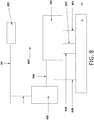
- FIG. 8 depicts an example oil circuit diagram of an oil system 10.
- the oil pump 100 receives oil from the sump 12 via the oil pick up 801.
- the oil pump 100 sends oil to the oil filter cooler assembly 802.
- the oil then flows to the main oil gallery 20.
- the pump 100 receives a constant feedback signal 803 from the main oil gallery 20.
- This feedback signal 803 may enter a spool valve chamber of oil pump 100.
- Regulated oil is discharged into the oil sump out of the regulation output port 804.
- a switch 805 receives oil from the oil gallery 20 and operates to switch between a high pressure set point and a low pressure set point. This switch may be a solenoid.
- the switch 805 operates by switching on the low set point signal 806 to the pump which may enter the spool valve.
- a pump may be equipped with an over-pressure discharge port 807 in case there is a blockage in the oil filter or engine. Similarly, the switch 805 may have a pressure relief port 808.
- FIG. 9 depicts an example of a conventional button filter 901 mounted in an oil pump.
- the button filter 901 is positioned inside of an oil port. Clogging particulates may build up on the button filter and block the flow of the entire oil port. Clogging of an entire oil passage may lead to catastrophic failure of engine components.
- FIG. 10 depicts other examples of mounting conventional filters in oil pumps.
- Filter 902 is fitted into a vertical drilling which is fed via a horizontal hole.
- Filter 902 is prone to filter clogging over time because oil only flows through the filter and not past it. Therefore, contamination will build up on the filter media until the filter is completely clogged.
- Filter 903 is located in a housing wall, however the filter 903 may be angled. Filters must commonly be angled if the housing wall is too thin to house the filter or if there isn't space for drill access. This design may allow oil to flow both past and through but may be expensive due to the angled drilling.
- Filter 904 is similar in principle to filter 903 but the filter 904 is located in the pump cover rather than the housing. Filter 904 may also be expensive to manufacture as it may require special casting and machining.
- Filter 905 fitted close to the spool valve chamber inlet hole, but this is easily clogged as oil only flows through it similarly to filter 902.
- the oil filter may maintain oil flow in the presence of clogging particulates.
- the large filter surface area will allows oil to flow in alternative path around clogging particulates. This may allow the filters to operate with a high level of clogging particulates than conventional filters.
- the alternative flow path is operable due to a large filter surface area and the filter surface area being located a distance from an oil port. This configuration allows the oil to flow through unclogged portions of the filter surface area and into the interior of the filter before passing into the port.
Applications Claiming Priority (1)
| Application Number | Priority Date | Filing Date | Title |
|---|---|---|---|
| GB1700951.5A GB2558916B (en) | 2017-01-19 | 2017-01-19 | A variable displacement oil pump including a filter for use in a motor vehicle |
Publications (2)
| Publication Number | Publication Date |
|---|---|
| EP3351755A1 true EP3351755A1 (fr) | 2018-07-25 |
| EP3351755B1 EP3351755B1 (fr) | 2021-03-03 |
Family
ID=58463066
Family Applications (1)
| Application Number | Title | Priority Date | Filing Date |
|---|---|---|---|
| EP18152048.7A Active EP3351755B1 (fr) | 2017-01-19 | 2018-01-17 | Système d'huile avec filtre à huile résistant au bouchage |
Country Status (6)
| Country | Link |
|---|---|
| US (1) | US10385741B2 (fr) |
| EP (1) | EP3351755B1 (fr) |
| CN (1) | CN108331633B (fr) |
| GB (1) | GB2558916B (fr) |
| MX (1) | MX2018000841A (fr) |
| RU (1) | RU2017146032A (fr) |
Families Citing this family (5)
| Publication number | Priority date | Publication date | Assignee | Title |
|---|---|---|---|---|
| CN107956533B (zh) * | 2017-12-14 | 2024-04-16 | 潍柴动力股份有限公司 | 一种具有流量调节阀的发动机 |
| US11078958B1 (en) | 2020-08-24 | 2021-08-03 | Apq Development, Llc | Compression limiter |
| USD921045S1 (en) | 2020-08-24 | 2021-06-01 | Apq Development, Llc | Oil pick-up assembly |
| USD916152S1 (en) | 2020-08-24 | 2021-04-13 | Apq Development, Llc | Compression limiter |
| US11028741B1 (en) | 2020-08-24 | 2021-06-08 | Apq Development, Llc | Oil pick-up assembly |
Citations (4)
| Publication number | Priority date | Publication date | Assignee | Title |
|---|---|---|---|---|
| JPH0777174A (ja) * | 1993-09-08 | 1995-03-20 | Nissan Motor Co Ltd | ベーンポンプ |
| US20060104823A1 (en) * | 2002-04-03 | 2006-05-18 | Borgwarner Inc. | Hydraulic pump with variable flow and variable pressure and electric control |
| US20130255617A1 (en) * | 2012-03-28 | 2013-10-03 | Honda Motor Co., Ltd. | Engine having oil pump |
| US20150218983A1 (en) * | 2012-09-07 | 2015-08-06 | Hitachi Automotive Systems, Ltd. | Variable-Capacity Oil Pump and Oil Supply System Using Same |
Family Cites Families (3)
| Publication number | Priority date | Publication date | Assignee | Title |
|---|---|---|---|---|
| EP1979616B1 (fr) * | 2006-01-31 | 2015-12-23 | Magna Powertrain Inc. | Systeme de pompe a palettes a cylindree variable et a pression variable |
| JP5920483B2 (ja) * | 2012-11-07 | 2016-05-18 | 日産自動車株式会社 | 内燃機関のオイル供給装置 |
| CN204984527U (zh) * | 2015-06-15 | 2016-01-20 | 湖南机油泵股份有限公司 | 一种先导式电磁阀单腔反馈可变排量叶片泵的控制系统 |
-
2017
- 2017-01-19 GB GB1700951.5A patent/GB2558916B/en not_active Expired - Fee Related
- 2017-12-26 RU RU2017146032A patent/RU2017146032A/ru not_active Application Discontinuation
-
2018
- 2018-01-17 US US15/873,821 patent/US10385741B2/en not_active Expired - Fee Related
- 2018-01-17 EP EP18152048.7A patent/EP3351755B1/fr active Active
- 2018-01-18 CN CN201810046956.3A patent/CN108331633B/zh not_active Expired - Fee Related
- 2018-01-19 MX MX2018000841A patent/MX2018000841A/es unknown
Patent Citations (4)
| Publication number | Priority date | Publication date | Assignee | Title |
|---|---|---|---|---|
| JPH0777174A (ja) * | 1993-09-08 | 1995-03-20 | Nissan Motor Co Ltd | ベーンポンプ |
| US20060104823A1 (en) * | 2002-04-03 | 2006-05-18 | Borgwarner Inc. | Hydraulic pump with variable flow and variable pressure and electric control |
| US20130255617A1 (en) * | 2012-03-28 | 2013-10-03 | Honda Motor Co., Ltd. | Engine having oil pump |
| US20150218983A1 (en) * | 2012-09-07 | 2015-08-06 | Hitachi Automotive Systems, Ltd. | Variable-Capacity Oil Pump and Oil Supply System Using Same |
Also Published As
| Publication number | Publication date |
|---|---|
| US10385741B2 (en) | 2019-08-20 |
| US20180202330A1 (en) | 2018-07-19 |
| GB201700951D0 (en) | 2017-03-08 |
| CN108331633B (zh) | 2022-02-15 |
| GB2558916A (en) | 2018-07-25 |
| RU2017146032A (ru) | 2019-06-26 |
| MX2018000841A (es) | 2018-11-09 |
| EP3351755B1 (fr) | 2021-03-03 |
| CN108331633A (zh) | 2018-07-27 |
| GB2558916B (en) | 2020-09-16 |
Similar Documents
| Publication | Publication Date | Title |
|---|---|---|
| EP3351755B1 (fr) | Système d'huile avec filtre à huile résistant au bouchage | |
| CN1811188B (zh) | 涡旋机 | |
| CN107893700B (zh) | 转换阀和可变压缩比内燃机的连杆 | |
| US20180156241A1 (en) | Motor and pump parts | |
| KR20220099576A (ko) | 슬라이딩 부품 | |
| EP2708750A1 (fr) | Compresseur à spirales | |
| EP4071344A1 (fr) | Ensemble soupape de filtre | |
| CA3135939A1 (fr) | Segment racleur | |
| US6715998B2 (en) | Intake regulator for compressed air in a reservoir | |
| CN105736381B (zh) | 具有可变的润滑剂喷射孔的压缩机系统 | |
| US8267116B2 (en) | Strainer and anti-backflow device for compressors | |
| JPH0217190Y2 (fr) | ||
| WO2019176476A1 (fr) | Compresseur | |
| CN111417784A (zh) | 供液式螺杆压缩机 | |
| JP2014202071A (ja) | スクリュー圧縮機 | |
| JP2008157174A (ja) | 容量可変型気体圧縮機 | |
| JP2004225702A (ja) | オイルモジュール | |
| US6629830B2 (en) | Pressure adjuster valve and gas compressor using the same | |
| CN110242574B (zh) | 旋转叶片式真空泵及其出口组件 | |
| KR100595726B1 (ko) | 스크롤 압축기의 압력조절장치 | |
| JP2007162587A (ja) | 気体圧縮機 | |
| JP7098333B2 (ja) | 油冷式スクリュ圧縮機 | |
| JP2018112130A (ja) | 圧縮機 | |
| JP2005226467A (ja) | 気体圧縮機 | |
| KR20220100707A (ko) | 슬라이딩 부품 |
Legal Events
| Date | Code | Title | Description |
|---|---|---|---|
| PUAI | Public reference made under article 153(3) epc to a published international application that has entered the european phase |
Free format text: ORIGINAL CODE: 0009012 |
|
| STAA | Information on the status of an ep patent application or granted ep patent |
Free format text: STATUS: THE APPLICATION HAS BEEN PUBLISHED |
|
| AK | Designated contracting states |
Kind code of ref document: A1 Designated state(s): AL AT BE BG CH CY CZ DE DK EE ES FI FR GB GR HR HU IE IS IT LI LT LU LV MC MK MT NL NO PL PT RO RS SE SI SK SM TR |
|
| AX | Request for extension of the european patent |
Extension state: BA ME |
|
| STAA | Information on the status of an ep patent application or granted ep patent |
Free format text: STATUS: REQUEST FOR EXAMINATION WAS MADE |
|
| 17P | Request for examination filed |
Effective date: 20180801 |
|
| RBV | Designated contracting states (corrected) |
Designated state(s): AL AT BE BG CH CY CZ DE DK EE ES FI FR GB GR HR HU IE IS IT LI LT LU LV MC MK MT NL NO PL PT RO RS SE SI SK SM TR |
|
| RIC1 | Information provided on ipc code assigned before grant |
Ipc: F16N 39/06 20060101ALI20200728BHEP Ipc: F01M 1/10 20060101AFI20200728BHEP Ipc: F01M 1/02 20060101ALN20200728BHEP Ipc: F16N 13/10 20060101ALI20200728BHEP Ipc: F16N 13/04 20060101ALI20200728BHEP Ipc: F01M 1/16 20060101ALI20200728BHEP |
|
| GRAP | Despatch of communication of intention to grant a patent |
Free format text: ORIGINAL CODE: EPIDOSNIGR1 |
|
| STAA | Information on the status of an ep patent application or granted ep patent |
Free format text: STATUS: GRANT OF PATENT IS INTENDED |
|
| INTG | Intention to grant announced |
Effective date: 20200925 |
|
| RIC1 | Information provided on ipc code assigned before grant |
Ipc: F01M 1/16 20060101ALI20200914BHEP Ipc: F16N 39/06 20060101ALI20200914BHEP Ipc: F01M 1/02 20060101ALN20200914BHEP Ipc: F16N 13/04 20060101ALI20200914BHEP Ipc: F16N 13/10 20060101ALI20200914BHEP Ipc: F01M 1/10 20060101AFI20200914BHEP |
|
| GRAS | Grant fee paid |
Free format text: ORIGINAL CODE: EPIDOSNIGR3 |
|
| STAA | Information on the status of an ep patent application or granted ep patent |
Free format text: STATUS: GRANT OF PATENT IS INTENDED |
|
| GRAA | (expected) grant |
Free format text: ORIGINAL CODE: 0009210 |
|
| STAA | Information on the status of an ep patent application or granted ep patent |
Free format text: STATUS: THE PATENT HAS BEEN GRANTED |
|
| AK | Designated contracting states |
Kind code of ref document: B1 Designated state(s): AL AT BE BG CH CY CZ DE DK EE ES FI FR GB GR HR HU IE IS IT LI LT LU LV MC MK MT NL NO PL PT RO RS SE SI SK SM TR |
|
| REG | Reference to a national code |
Ref country code: GB Ref legal event code: FG4D |
|
| REG | Reference to a national code |
Ref country code: AT Ref legal event code: REF Ref document number: 1367435 Country of ref document: AT Kind code of ref document: T Effective date: 20210315 Ref country code: CH Ref legal event code: EP |
|
| REG | Reference to a national code |
Ref country code: DE Ref legal event code: R096 Ref document number: 602018013206 Country of ref document: DE |
|
| REG | Reference to a national code |
Ref country code: IE Ref legal event code: FG4D |
|
| REG | Reference to a national code |
Ref country code: LT Ref legal event code: MG9D |
|
| PG25 | Lapsed in a contracting state [announced via postgrant information from national office to epo] |
Ref country code: LT Free format text: LAPSE BECAUSE OF FAILURE TO SUBMIT A TRANSLATION OF THE DESCRIPTION OR TO PAY THE FEE WITHIN THE PRESCRIBED TIME-LIMIT Effective date: 20210303 Ref country code: BG Free format text: LAPSE BECAUSE OF FAILURE TO SUBMIT A TRANSLATION OF THE DESCRIPTION OR TO PAY THE FEE WITHIN THE PRESCRIBED TIME-LIMIT Effective date: 20210603 Ref country code: NO Free format text: LAPSE BECAUSE OF FAILURE TO SUBMIT A TRANSLATION OF THE DESCRIPTION OR TO PAY THE FEE WITHIN THE PRESCRIBED TIME-LIMIT Effective date: 20210603 Ref country code: FI Free format text: LAPSE BECAUSE OF FAILURE TO SUBMIT A TRANSLATION OF THE DESCRIPTION OR TO PAY THE FEE WITHIN THE PRESCRIBED TIME-LIMIT Effective date: 20210303 Ref country code: GR Free format text: LAPSE BECAUSE OF FAILURE TO SUBMIT A TRANSLATION OF THE DESCRIPTION OR TO PAY THE FEE WITHIN THE PRESCRIBED TIME-LIMIT Effective date: 20210604 Ref country code: HR Free format text: LAPSE BECAUSE OF FAILURE TO SUBMIT A TRANSLATION OF THE DESCRIPTION OR TO PAY THE FEE WITHIN THE PRESCRIBED TIME-LIMIT Effective date: 20210303 |
|
| REG | Reference to a national code |
Ref country code: NL Ref legal event code: MP Effective date: 20210303 |
|
| REG | Reference to a national code |
Ref country code: AT Ref legal event code: MK05 Ref document number: 1367435 Country of ref document: AT Kind code of ref document: T Effective date: 20210303 |
|
| PG25 | Lapsed in a contracting state [announced via postgrant information from national office to epo] |
Ref country code: SE Free format text: LAPSE BECAUSE OF FAILURE TO SUBMIT A TRANSLATION OF THE DESCRIPTION OR TO PAY THE FEE WITHIN THE PRESCRIBED TIME-LIMIT Effective date: 20210303 Ref country code: LV Free format text: LAPSE BECAUSE OF FAILURE TO SUBMIT A TRANSLATION OF THE DESCRIPTION OR TO PAY THE FEE WITHIN THE PRESCRIBED TIME-LIMIT Effective date: 20210303 Ref country code: RS Free format text: LAPSE BECAUSE OF FAILURE TO SUBMIT A TRANSLATION OF THE DESCRIPTION OR TO PAY THE FEE WITHIN THE PRESCRIBED TIME-LIMIT Effective date: 20210303 Ref country code: PL Free format text: LAPSE BECAUSE OF FAILURE TO SUBMIT A TRANSLATION OF THE DESCRIPTION OR TO PAY THE FEE WITHIN THE PRESCRIBED TIME-LIMIT Effective date: 20210303 |
|
| PG25 | Lapsed in a contracting state [announced via postgrant information from national office to epo] |
Ref country code: NL Free format text: LAPSE BECAUSE OF FAILURE TO SUBMIT A TRANSLATION OF THE DESCRIPTION OR TO PAY THE FEE WITHIN THE PRESCRIBED TIME-LIMIT Effective date: 20210303 |
|
| PG25 | Lapsed in a contracting state [announced via postgrant information from national office to epo] |
Ref country code: CZ Free format text: LAPSE BECAUSE OF FAILURE TO SUBMIT A TRANSLATION OF THE DESCRIPTION OR TO PAY THE FEE WITHIN THE PRESCRIBED TIME-LIMIT Effective date: 20210303 Ref country code: EE Free format text: LAPSE BECAUSE OF FAILURE TO SUBMIT A TRANSLATION OF THE DESCRIPTION OR TO PAY THE FEE WITHIN THE PRESCRIBED TIME-LIMIT Effective date: 20210303 Ref country code: SM Free format text: LAPSE BECAUSE OF FAILURE TO SUBMIT A TRANSLATION OF THE DESCRIPTION OR TO PAY THE FEE WITHIN THE PRESCRIBED TIME-LIMIT Effective date: 20210303 Ref country code: AT Free format text: LAPSE BECAUSE OF FAILURE TO SUBMIT A TRANSLATION OF THE DESCRIPTION OR TO PAY THE FEE WITHIN THE PRESCRIBED TIME-LIMIT Effective date: 20210303 |
|
| PG25 | Lapsed in a contracting state [announced via postgrant information from national office to epo] |
Ref country code: IS Free format text: LAPSE BECAUSE OF FAILURE TO SUBMIT A TRANSLATION OF THE DESCRIPTION OR TO PAY THE FEE WITHIN THE PRESCRIBED TIME-LIMIT Effective date: 20210703 Ref country code: PT Free format text: LAPSE BECAUSE OF FAILURE TO SUBMIT A TRANSLATION OF THE DESCRIPTION OR TO PAY THE FEE WITHIN THE PRESCRIBED TIME-LIMIT Effective date: 20210705 Ref country code: RO Free format text: LAPSE BECAUSE OF FAILURE TO SUBMIT A TRANSLATION OF THE DESCRIPTION OR TO PAY THE FEE WITHIN THE PRESCRIBED TIME-LIMIT Effective date: 20210303 Ref country code: SK Free format text: LAPSE BECAUSE OF FAILURE TO SUBMIT A TRANSLATION OF THE DESCRIPTION OR TO PAY THE FEE WITHIN THE PRESCRIBED TIME-LIMIT Effective date: 20210303 |
|
| REG | Reference to a national code |
Ref country code: DE Ref legal event code: R097 Ref document number: 602018013206 Country of ref document: DE |
|
| PLBE | No opposition filed within time limit |
Free format text: ORIGINAL CODE: 0009261 |
|
| STAA | Information on the status of an ep patent application or granted ep patent |
Free format text: STATUS: NO OPPOSITION FILED WITHIN TIME LIMIT |
|
| PG25 | Lapsed in a contracting state [announced via postgrant information from national office to epo] |
Ref country code: ES Free format text: LAPSE BECAUSE OF FAILURE TO SUBMIT A TRANSLATION OF THE DESCRIPTION OR TO PAY THE FEE WITHIN THE PRESCRIBED TIME-LIMIT Effective date: 20210303 Ref country code: AL Free format text: LAPSE BECAUSE OF FAILURE TO SUBMIT A TRANSLATION OF THE DESCRIPTION OR TO PAY THE FEE WITHIN THE PRESCRIBED TIME-LIMIT Effective date: 20210303 Ref country code: DK Free format text: LAPSE BECAUSE OF FAILURE TO SUBMIT A TRANSLATION OF THE DESCRIPTION OR TO PAY THE FEE WITHIN THE PRESCRIBED TIME-LIMIT Effective date: 20210303 |
|
| 26N | No opposition filed |
Effective date: 20211206 |
|
| PG25 | Lapsed in a contracting state [announced via postgrant information from national office to epo] |
Ref country code: SI Free format text: LAPSE BECAUSE OF FAILURE TO SUBMIT A TRANSLATION OF THE DESCRIPTION OR TO PAY THE FEE WITHIN THE PRESCRIBED TIME-LIMIT Effective date: 20210303 |
|
| PG25 | Lapsed in a contracting state [announced via postgrant information from national office to epo] |
Ref country code: IT Free format text: LAPSE BECAUSE OF FAILURE TO SUBMIT A TRANSLATION OF THE DESCRIPTION OR TO PAY THE FEE WITHIN THE PRESCRIBED TIME-LIMIT Effective date: 20210303 |
|
| PGFP | Annual fee paid to national office [announced via postgrant information from national office to epo] |
Ref country code: DE Payment date: 20211216 Year of fee payment: 5 |
|
| PG25 | Lapsed in a contracting state [announced via postgrant information from national office to epo] |
Ref country code: IS Free format text: LAPSE BECAUSE OF FAILURE TO SUBMIT A TRANSLATION OF THE DESCRIPTION OR TO PAY THE FEE WITHIN THE PRESCRIBED TIME-LIMIT Effective date: 20210703 |
|
| PG25 | Lapsed in a contracting state [announced via postgrant information from national office to epo] |
Ref country code: MC Free format text: LAPSE BECAUSE OF FAILURE TO SUBMIT A TRANSLATION OF THE DESCRIPTION OR TO PAY THE FEE WITHIN THE PRESCRIBED TIME-LIMIT Effective date: 20210303 |
|
| REG | Reference to a national code |
Ref country code: CH Ref legal event code: PL |
|
| GBPC | Gb: european patent ceased through non-payment of renewal fee |
Effective date: 20220117 |
|
| REG | Reference to a national code |
Ref country code: BE Ref legal event code: MM Effective date: 20220131 |
|
| PG25 | Lapsed in a contracting state [announced via postgrant information from national office to epo] |
Ref country code: LU Free format text: LAPSE BECAUSE OF NON-PAYMENT OF DUE FEES Effective date: 20220117 Ref country code: GB Free format text: LAPSE BECAUSE OF NON-PAYMENT OF DUE FEES Effective date: 20220117 |
|
| PG25 | Lapsed in a contracting state [announced via postgrant information from national office to epo] |
Ref country code: FR Free format text: LAPSE BECAUSE OF NON-PAYMENT OF DUE FEES Effective date: 20220131 Ref country code: BE Free format text: LAPSE BECAUSE OF NON-PAYMENT OF DUE FEES Effective date: 20220131 |
|
| PG25 | Lapsed in a contracting state [announced via postgrant information from national office to epo] |
Ref country code: LI Free format text: LAPSE BECAUSE OF NON-PAYMENT OF DUE FEES Effective date: 20220131 Ref country code: CH Free format text: LAPSE BECAUSE OF NON-PAYMENT OF DUE FEES Effective date: 20220131 |
|
| PG25 | Lapsed in a contracting state [announced via postgrant information from national office to epo] |
Ref country code: IE Free format text: LAPSE BECAUSE OF NON-PAYMENT OF DUE FEES Effective date: 20220117 |
|
| REG | Reference to a national code |
Ref country code: DE Ref legal event code: R119 Ref document number: 602018013206 Country of ref document: DE |
|
| PG25 | Lapsed in a contracting state [announced via postgrant information from national office to epo] |
Ref country code: DE Free format text: LAPSE BECAUSE OF NON-PAYMENT OF DUE FEES Effective date: 20230801 |
|
| PG25 | Lapsed in a contracting state [announced via postgrant information from national office to epo] |
Ref country code: HU Free format text: LAPSE BECAUSE OF FAILURE TO SUBMIT A TRANSLATION OF THE DESCRIPTION OR TO PAY THE FEE WITHIN THE PRESCRIBED TIME-LIMIT; INVALID AB INITIO Effective date: 20180117 |