EP3351672B1 - Needle clamp for sewing machine comprising a needle cooling device and method of cooling a needle - Google Patents
Needle clamp for sewing machine comprising a needle cooling device and method of cooling a needle Download PDFInfo
- Publication number
- EP3351672B1 EP3351672B1 EP17152910.0A EP17152910A EP3351672B1 EP 3351672 B1 EP3351672 B1 EP 3351672B1 EP 17152910 A EP17152910 A EP 17152910A EP 3351672 B1 EP3351672 B1 EP 3351672B1
- Authority
- EP
- European Patent Office
- Prior art keywords
- needle
- cooling device
- thermoelectric cooling
- needle clamp
- clamp
- Prior art date
- Legal status (The legal status is an assumption and is not a legal conclusion. Google has not performed a legal analysis and makes no representation as to the accuracy of the status listed.)
- Active
Links
Images

Classifications
-
- D—TEXTILES; PAPER
- D05—SEWING; EMBROIDERING; TUFTING
- D05B—SEWING
- D05B71/00—Lubricating or cooling devices
- D05B71/04—Needle cooling devices
-
- D—TEXTILES; PAPER
- D05—SEWING; EMBROIDERING; TUFTING
- D05B—SEWING
- D05B55/00—Needle holders; Needle bars
- D05B55/02—Devices for fastening needles to needle bars
-
- D—TEXTILES; PAPER
- D05—SEWING; EMBROIDERING; TUFTING
- D05D—INDEXING SCHEME ASSOCIATED WITH SUBCLASSES D05B AND D05C, RELATING TO SEWING, EMBROIDERING AND TUFTING
- D05D2303/00—Applied objects or articles
- D05D2303/40—Electronic or electrical components
Definitions
- the present invention relates to the field of textile industry and to the sewing process applied to the production of garments. More in detail, the present invention relates to the cooling of a needle used in sewing machines and overheated during sewing operations.
- the sewing process is an important step of the production of garments. Basically, the sewing process involves fastening of fabrics, or other materials, with the help of a needle and threads.
- needles of sewing machines, or overlock machines are subjected to an increment of temperature due to friction between the needle and the portions of the garment that are being sewn together.
- needles may overheat up to high temperatures. In many circumstances, in correspondence of the sewing needle tip or needle eye, temperatures as high as 300°C have been measured. Such high temperatures during the stitching process may damage both the textile material of the garment and the sewing needle.
- portions of the stitch and of the fabric go into melting, resulting in critical effects for both functionality and aesthetic appearance of the seam and the entire garment.
- Heat is naturally dispersed from the overheated needle through spontaneous heat dispersion such as radiation, convection and conduction.
- an object with a non-null temperature such as the needle in the case of sewing processes, emits a radiation that result in an output thermal power.
- radiation plays a relatively small role in the needle cooling during sewing operations.
- Thermal convection is a heat transfer generated by the movement of fluids that surround an object.
- convection heat transfer is caused by the needles movement in air during the oscillating movement of needles during sewing operations.
- Thermal conduction is a heat transfer generated by diffusion and microscopic collision of particles within a body or between contiguous bodies. In the case of sewing needles, it represents the most important heat dispersion component that induces needles decreasing its temperature when the machine stops. The heat flows by conduction from the overheated needle to the retaining means of the needle, to the arm of the sewing machine and to the entire sewing machine.
- Document US2690148 discloses a device for cooling an overheated sewing machine needle during sewing operations. More in detail, it discloses a needle cooler comprising a hollow C-shaped body that has an inlet communicating with a flexible hose that in turn communicates with a supply of cooling medium under pressure. The C-shaped body is connected to the clamp screw that retains the needle in a fixed position during sewing operations. The lower part of the C-shaped body is a hollow chamber with a series of spaced jet outlet passages inclined so that they converge upon a common point at which the eye of the needle is located. The cooling effect of the needle is obtained by convection performed by turbulent jet streams.
- the structure of the cooling device is complex and the cooling effect obtained by turbulent jet streams may imply the interaction of jet streams with the fabric materials that is positioned close to the eye of the needle where the jet streams converge.
- Document US2316647 discloses a needle cooling device for sewing machines comprising a coolant reservoir and liquid dispensing means so that liquid coolant is applied to the needle at each reciprocation.
- the cooling device is provided with a container comprising an absorbent fibre able to carry the desired amount of liquid coolant.
- the needle descends it will pass through the fibre and will pick up from the fibre the liquid that will cause the cooling of the needle.
- the needle tip and the needle eye are subject to a decrease in temperature.
- the cooling effect of the needle is obtained by convection performed by the liquid coolant and by conduction, performed by the contact between the sewing needle and the absorbent fibre with the liquid coolant.
- the cooling effect is not continuous and during its movement, the needle carries the liquid coolant picked up from the absorbent fibre of the cooling device. In this way, during sewing operations, the liquid coolant can interact with the fabric material when the needle passes through the portions of the garment.
- the known methods for cooling sewing needles disclose devices that use cooling fluids for cooling overheated needles during sewing operations.
- cooling fluids interact with the needle, causing the needle to decrease its temperature, but the cooling fluids interact with the fabric material too.
- cooling fluids provide invasive effects that can damage the fabric.
- many fabric materials are temperature sensitive and cooling fluids on the fabric may result in a deterioration of the portion in contact with the cooling fluids.
- the known cooling system for sewing machine especially those using cooling fluids, are difficult and expensive to maintain.
- the known cooling system requires high maintenance time and costs.
- Another aim of the present invention is to obtain an effective cooling of the needle without interacting with the fabric material too. More in detail, an aim of the present invention is to provide a cooling device that causes the sewing needle to decrease its temperature preferably through a conduction heat transfer method.
- Another aim of the present invention is to provide a cooling device that can be constrained to existing sewing machines without modification of the existing sewing machines.
- Another aim of the present invention is to provide costs and weight savings in cooling overheated sewing needles, by means of a cooling device that can offer high efficiency and good control of the thermal power subtracted from the overheated needle.
- a needle clamp for a sewing machine, comprising a body at least partially made of a thermally conductive material and having retaining means for constraining a needle.
- the needle clamp comprises a thermoelectric cooling device directly or indirectly constrained to a portion of the body of the needle clamp allowing heat transfer, preferably by conduction, from the needle to cool it.
- thermoelectric cooling devices are used herein to indicate devices able to transform temperature differences (heat) to electric energy, and viceversa. These devices are also known in the art as Peltier/Seebeck devices. According to the present invention the thermoelectric device of the needle clamp is able to cool the needle constrained to the needle clamp. In other words, heat is transferred (preferably by conduction) from the needle clamp, and thus from the needle constrained to it, through the thermoelectric device.
- the thermoelectric cooling device is provided with a first side (preferably a cold side) and a second side or external side (preferably a hot side), the first side is directly or indirectly constrained to a portion of the body of the needle clamp allowing heat transfer, preferably by conduction, from the needle clamp (and thus from the needle) to the first side and then to the second side of the thermoelectric device, and thus to the external environment.
- one or more heat sink can be arranged on the second side (external side of the thermoelectric device) to increase heat dissipation.
- thermoelectric cooling device is provided with a hot side and a cold side, the cold side being directly or indirectly constrained to a portion of the body of the needle clamp allowing heat transfer, preferably by conduction, from the needle to said cold side and thus to external environment.
- the thermoelectric cooling device comprises at least a Peltier cell, and it is constrained directly or indirectly to an external surface of the body of the needle clamp. It has to be noted that the term “directly constrained” herein refers to the direct contact of the thermoelectric cooling device with the body of the needle clamp.
- thermoelectric cooling device is constrained by constraining means, as an example screws, rivets, or is constrained by interlocking the cooling device in a seat, so that the cooling device is in direct contact with the body of the needle clamp.
- an additional layer may comprises a thermal conductive layer that is able to allow the heat flow from the body of the needle clamp to thermoelectric device, e.g. the cold side of a Peltier cell.
- the thermal conductive layer is advantageously an adhesive layer, as an example a thermal paste, that can indirectly constrain (i.e. constrain with the interposition of the adhesive layer) the thermoelectric device, e.g. a Peltier cell, to the external surface of the body of the needle clamp.
- thermoelectric cooling device is connected to a control unit for the regulation of the thermoelectric device, for example by a selective activation/deactivation and/or by a regulation of the electric current provided to it.
- a control unit for the regulation of the thermoelectric device, for example by a selective activation/deactivation and/or by a regulation of the electric current provided to it.
- the sewing needle cooling can be controlled by a different setting of the intensity of voltage across the electric poles of the thermoelectric device.
- the intensity of the electric voltage across the thermoelectric device poles by changing the intensity of the electric voltage across the thermoelectric device poles, the temperature of the cold side constrained to the body of the needle clamp changes and a different amount of heat will be transferred from the overheated sewing needle to the thermoelectric cooling device and thus to the external environment.
- the thermoelectric device is regulated, preferably by a control unit, according to feedback loop control.
- a PID controller or any other negative feedback loop control device can control the heat transferred through the thermoelectric device.
- a PID controller or any other negative feedback loop control device can control the current through the peltier/seebeck thermoelectric device to alter the pumped heat from the needle clamp outwards.
- heat can be transferred to a heat dissipation element (heat sink) in contact with the thermoelectric devices on their open side (second side) facing the external environment.
- heat sink heat dissipation element
- a temperature sensor such as a thermocouple, can be provided to detect temperature of the needle clamp and/or directly of the needle.
- the generated temperature sensor value can be used in said feedback loop control.
- the temperature of the needle clamp and hence of the needle can easily be maintained at a constant level.
- thermoelectric device can be controlled according to an open loop control system, e.g. without a feedback control discussed above.
- the temperature can be manually adjusted by an operator, e.g. by maintaining the temperature at a minimum that can be defined by the current system parameters.
- the sewing machine has an electric circuit connected to an electric power source, and the thermoelectric cooling device is connected to said electric circuit of said sewing machine.
- the thermoelectric cooling device uses the same electric power source of the sewing machine for cooling the cold side of the cooling device. In this way, it is possible to use just one electric power source reducing the complexity and the encumbrance of a further electric power source different from the power source of the sewing machine.
- Another aspect of the present invention provides for a method of cooling a needle retained by a needle clamp for a sewing machine, said needle clamp comprising a body at least partially made of a thermally conductive material and having retaining means for constraining at least one needle, comprising the steps of:
- thermoelectric cooling device e.g. a Peltier cell
- the needle clamp 1 comprises a body 2 constrained to an arm 12 of a sewing machine.
- the needle clamp 1 is configured to retain a needle 10 during sewing operations.
- the needle 10 is retained in the needle clamp 1 by accommodating the needle 10 in a recessed seat 11 provided in the body 2 of the needle clamp 1.
- retaining means 3 intended to constrain the needle 1 in a removable manner (i.e. reversibly) to the needle clamp 2.
- the retaining means 3 also allow to remove the needle 1 from the recessed seat 11 of the needle clamp 1 in case of maintenance or when it is necessary to replace a used needle with a new needle, or when a needle with different characteristics has to be used according to the fabric to be sewn.
- retaining means 3 comprises a clamping pin and a knob 4 that when screwed in a correspondent threated hole, reversibly constrain the clamping pin and the needle 1 in the recessed seat 11 of the body 2 of the needle clamp 1.
- the retaining means can be provided with different configuration with respect to that disclosed above and shown in the figures, provided that the needle can be retained in the needle clamp.
- the recessed seat 11 accommodating the needle 10 in the body 2 of the needle clamp 1 is preferably provided with a longitudinal extension according to an axis A-A'.
- the axis A-A' extends in the same direction of the longitudinal axis of the needle 10, when the needle 10 is accommodated in the recessed seat 11 of the body 2 of the needle clamp 1.
- the body 2 of the needle clamp 1 is at least partially made of a thermally conductive material.
- a conductive material used for the body 2 of the needle clamp 1 is a metallic material.
- the retaining means 3 for retaining the needle in the recessed seat 11 in the body 2 of the needle clamp 1 is at least partially made of a thermally conductive material, as an example a metallic material.
- the arm 12, the body 2 of the needle clamp 1 and the needle 10 move along the axis A-A'.
- the needle 10 penetrates the fabric, the friction between the sewing needle 10 and the fabric, generates the overheating of the needle 10.
- the needle overheating can result in a severe increment in temperature of the needle 10, causing the damage of the seam, of the fabric, of the needle, or a combination thereof.
- the needle clamp 1 according to the present invention, comprises a thermoelectric cooling device 5 constrained to the body 2 of the needle clamp 1.
- thermoelectric cooling device 5 is a device able to transfer heat from one side of the device, to the other side, by means of electric energy.
- the effect that correlates a difference in voltage to a difference in temperature also known with the term thermoelectric effect, is obtained by a device comprising two types of semiconductors placed thermally in parallel and electrically in series.
- thermoelectric effect is obtained by a device comprising two types of semiconductors placed thermally in parallel and electrically in series.
- thermoelectric devices can be used both as cooler devices and as thermoelectric generator.
- Thermoelectric devices known as Peltier cells
- Thermoelectric devices known as Seebeck cells, convert a difference in temperature between two sides of the device in electricity.
- the thermoelectric cooling device 5 such as at least one Peltier cell, comprises a hot side 6 and a cold side 7.
- the thermoelectric effect is used to transfer heat from the needle clamp to a first side of the device, e.g. a cold side 7, to a second side 6, e.g. a hot side 6.
- electric power can be used to generate, by thermoelectric effect, a difference in temperature between the two sides 6,7 of the thermoelectric device 5, thus allowing heat transfer from the needle clamp.
- thermoelectric cooling device 5 e.g. a Peltier cell
- the thermoelectric cooling device 5 is constrained to a portion of the body 2 of the needle clamp 1 and, more in detail, the thermoelectric cooling device 5 is constrained to a portion of the external surface of the body 2.
- the thermoelectric cooling device 5 extends on a portion of said body 2 of an angle ⁇ comprised between 0° and 360°, preferably between 0° and 270°, in a plane perpendicular to the axis A-A' that extends along the longitudinal extension of the recessed seat 11 and the longitudinal axis of the needle 10.
- thermoelectric cooling device 5 is constrained to the body 2 of the needle clamp 1 directly or indirectly.
- the cooling device 5 is directly constrained to the external surface of the needle clamp 1 by contacting the first side 7 of the cooling device 5 with a portion of the external surface of the body 2 of the needle clamp 1.
- Retaining means for retaining the cooling device on the body 2 in a direct constraint may comprise screws, rivets or protruding elements protruding from the external surface of the body 2 suitable to interface directly the cooling device 5, the cooling device 5 and the body 2 of the needle clamp 1 for example by interlocking the cooling device 5 in said protruding elements.
- the cooling device 5 is indirectly constrained to the external surface of the needle clamp 1 by interposing an additional layer between the first side 7 of the cooling device 5 and the external surface of the body 2 of the needle clamp 1.
- the additional layer is a thermal conductive layer 8, such as a thermal past.
- the additional thermal conductive layer is an adhesive layer that constrains the cooling device 5 on the external surface of the body 2 of the needle clamp 1.
- an adhesive thermal paste adheres from one side to the cold side 7 of the cooling device 5 and on the other side to the external surface of the body 2 of the needle clamp 1.
- thermoelectric cooling device 5 is thermally in contact with the needle 10 since heat flows from the needle 10 to the cooling device 5, preferably by conduction.
- the cooling power of the thermoelectric cooling device 5 can be controlled by the electric power supplied to the cooling device 5.
- the regulation of the electric power supplied to the cooling device 5 results in a regulation of the temperature of the cold side 7 of the cooling device 5.
- the intensity of the heat flow from the overheated needle to the cold side 7 of the cooling device is a function of the difference in temperature between the needle 10 and the cold side 7 of the cooling device 5, the cooling effect of the needle 10 and the temperature of the needle 10 can be controlled by the regulation of the electric power supplied to the cooling device 5.
- a heat dissipation element e.g. heat sink
- a heat dissipation element can be provided and preferably constrained to the second (external) side 6 of the thermoelectric device to increase heat transfer to the external environment.
- At least one temperature sensor e.g. a thermocouple
- the generated temperature sensor value can be used to control the thermoelectric device.
- thermoelectric device and thus the heat transfer from the needle clamp to the external environment can be carried out manually, e.g. by an operator that activates/deactivates the thermoelectric device or that regulates the electric current provided to the thermoelectric device, e.g. to a Peltier cell.
- thermoelectric device can be controlled automatically, for example by a feedback loop control of the thermoelectric device.
- a PID controller or any other negative feedback loop control device can control the current through the thermoelectric device to alter the pumped heat (transferred heat) from the needle clamp outwards.
- thermoelectric device can be advantageously carried out automatically e.g. by regulating the electric current provided to the thermoelectric device, e.g. to a Peltier cell.
- the sewing machine has an electric circuit connected to an electric power source, and advantageously, the thermoelectric cooling device 5 is connected to said electric circuit of said sewing machine.
- the thermoelectric cooling device 5 uses the same electric power source of the sewing machine for cooling the cold side 7 of the cooling device 5. In this way, it is possible to use just one electric power source reducing the complexity and the encumbrance of a further electric power source different from the power source of the sewing machine.
- the present invention also discloses a method for cooling a needle 10 retained by a needle clamp 1 for a sewing machine, comprising the step of constraining directly or indirectly a thermoelectric cooling device 5 to a portion of said body 2, and the step of regulating the thermoelectric cooling device 5.
- the method also comprise the step of providing electric power to said thermoelectric cooling device 5, e.g. a Peltier cell.
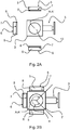
- thermoelectric cooling device 5 is indirectly constrained to a portion of the external surface of said body 2 according to step a) of the method according to the present invention, as shown in figures 2a, b.
- Figure 2a shows a top view of the needle clamp 1 and three external free surfaces of the body 2 of the needle clamp 1.
- the thermoelectric cooling device 5 comprises three Peltier cells, each comprising a hot side 6 and a cold side 7.
- An adhesive thermal paste 8 is adhered on one side on the cold side 7 of the Peltier cells, and on the other side is suitable to adhere on a portion of the external surfaces of the body 2 of the needle clamp 1.
- Figure 2b shows the same view of the needle clamp 1 and the thermoelectric cooling device 5 of figure 2a , after the adhesion of the Peltier cells on the portion of the external surfaces of the body 2 of the needle clamp 1, according to the present invention.
- the cold side 7 of the Peltier cells decrease in temperature according to the thermoelectric effect. As long as the temperature of the cold side 7 of the thermoelectric device 5 is lower than the temperature of the needle clamp 1 and of the needle 10 overheated by friction during sewing operations, an heat flow occurs from the needle 10 to the thermoelectric device 5, and thus to the second side 6 (external side) of the thermoelectric device and thus to the external ambient.
Landscapes
- Engineering & Computer Science (AREA)
- Textile Engineering (AREA)
- Mechanical Engineering (AREA)
- Sewing Machines And Sewing (AREA)
Priority Applications (10)
| Application Number | Priority Date | Filing Date | Title |
|---|---|---|---|
| ES17152910T ES2808956T3 (es) | 2017-01-24 | 2017-01-24 | Porta agujas para máquina de coser que comprende un dispositivo de enfriamiento de aguja y procedimiento de enfriamiento de aguja |
| PT171529100T PT3351672T (pt) | 2017-01-24 | 2017-01-24 | Fixador de agulha para máquina de costura compreendendo um dispositivo de arrefecimento de agulha e método de arrefecimento de uma agulha |
| DK17152910.0T DK3351672T3 (da) | 2017-01-24 | 2017-01-24 | Nåleholder til symaskine omfattende en nålekøleanordning og fremgangsmåde til afkøling af en nål |
| EP17152910.0A EP3351672B1 (en) | 2017-01-24 | 2017-01-24 | Needle clamp for sewing machine comprising a needle cooling device and method of cooling a needle |
| PL17152910T PL3351672T3 (pl) | 2017-01-24 | 2017-01-24 | Zacisk igły do maszyny do szycia zawierający urządzenie chłodzące igłę i sposób chłodzenia igły |
| JP2017233192A JP7058113B2 (ja) | 2017-01-24 | 2017-12-05 | 針の冷却装置を有するミシン用の針クランプ |
| US15/852,258 US10604876B2 (en) | 2017-01-24 | 2017-12-22 | Needle clamp for sewing machine comprising a needle cooling device |
| BR102018000042-0A BR102018000042B1 (pt) | 2017-01-24 | 2018-01-02 | Braçadeira de agulha para máquina de costura, máquina de costura, uso de um dispositivo de arrefecimento termoelétrico e método para arrefecer uma agulha retida por uma braçadeira de agulha a uma máquina de costura |
| PCT/EP2018/050284 WO2018137911A1 (en) | 2017-01-24 | 2018-01-05 | Needle clamp for sewing machine comprising a needle cooling device and method of cooling a needle |
| CN201810021561.8A CN108342845B (zh) | 2017-01-24 | 2018-01-10 | 包括针冷却装置的缝纫机用针夹 |
Applications Claiming Priority (1)
| Application Number | Priority Date | Filing Date | Title |
|---|---|---|---|
| EP17152910.0A EP3351672B1 (en) | 2017-01-24 | 2017-01-24 | Needle clamp for sewing machine comprising a needle cooling device and method of cooling a needle |
Publications (2)
| Publication Number | Publication Date |
|---|---|
| EP3351672A1 EP3351672A1 (en) | 2018-07-25 |
| EP3351672B1 true EP3351672B1 (en) | 2020-05-13 |
Family
ID=57890714
Family Applications (1)
| Application Number | Title | Priority Date | Filing Date |
|---|---|---|---|
| EP17152910.0A Active EP3351672B1 (en) | 2017-01-24 | 2017-01-24 | Needle clamp for sewing machine comprising a needle cooling device and method of cooling a needle |
Country Status (10)
| Country | Link |
|---|---|
| US (1) | US10604876B2 (da) |
| EP (1) | EP3351672B1 (da) |
| JP (1) | JP7058113B2 (da) |
| CN (1) | CN108342845B (da) |
| BR (1) | BR102018000042B1 (da) |
| DK (1) | DK3351672T3 (da) |
| ES (1) | ES2808956T3 (da) |
| PL (1) | PL3351672T3 (da) |
| PT (1) | PT3351672T (da) |
| WO (1) | WO2018137911A1 (da) |
Families Citing this family (1)
| Publication number | Priority date | Publication date | Assignee | Title |
|---|---|---|---|---|
| CN111705439B (zh) * | 2020-06-10 | 2021-11-16 | 陵川县金丰科技股份有限公司 | 一种纺织用缝纫机 |
Family Cites Families (26)
| Publication number | Priority date | Publication date | Assignee | Title |
|---|---|---|---|---|
| US2080322A (en) * | 1933-04-05 | 1937-05-11 | Union Special Machine Co | Needle cooling device for sewing machines |
| US2316647A (en) | 1941-11-07 | 1943-04-13 | Premier Thread Company | Needle cooling device |
| US2423996A (en) * | 1942-03-07 | 1947-07-15 | Union Special Machine Co | Sewing machine |
| US2593203A (en) * | 1949-10-19 | 1952-04-15 | Ignatius Billera | Needle cooling device for sewing machines |
| US2690148A (en) | 1951-11-10 | 1954-09-28 | Coats & Clark | Sewing machine needle cooler |
| GB1219760A (en) * | 1967-12-30 | 1971-01-20 | Wood Bastow & Company Ltd | Improvements in or relating to sewing machines |
| IT983801B (it) * | 1973-04-12 | 1974-11-11 | Virginio Rimoldi E C Spa | Supporto universale per gruppo raffreddatore degli aghi di una macchina per cucire |
| FR2248756A5 (en) * | 1973-10-22 | 1975-05-16 | Mimefil | Preventing overheating of element in textile machine - by monitoring temp. and reducing speed of drive mechanism |
| JPS5418344B2 (da) | 1974-09-27 | 1979-07-06 | ||
| DE2551133C2 (de) * | 1975-11-14 | 1983-10-06 | Kessler, Karl H., Ing.(grad.), 7300 Esslingen | Steuereinrichtung für eine Nähmaschine |
| JPS5138438Y1 (da) * | 1975-12-27 | 1976-09-20 | ||
| US4305339A (en) * | 1979-09-28 | 1981-12-15 | Vortec Corporation | Vortex tube assembly for cooling sewing machine needle |
| US4480565A (en) * | 1981-11-06 | 1984-11-06 | Union Special Corporation | Sewing machine needle cooler |
| US4489742A (en) * | 1983-07-21 | 1984-12-25 | Energy Conversion Devices, Inc. | Thermoelectric device and method of making and using same |
| JPH10235061A (ja) * | 1997-03-03 | 1998-09-08 | Matsuya R & D:Kk | 針冷却装置を具えるミシン |
| JP2003019379A (ja) | 2001-05-01 | 2003-01-21 | Juki Corp | ミシンの冷却装置 |
| JP2004113418A (ja) * | 2002-09-26 | 2004-04-15 | Brother Ind Ltd | ミシン |
| WO2005041314A2 (en) * | 2003-10-29 | 2005-05-06 | Elasthermo Ltd. | Thermoelectric device and system |
| US20060048809A1 (en) * | 2004-09-09 | 2006-03-09 | Onvural O R | Thermoelectric devices with controlled current flow and related methods |
| AT507533B1 (de) * | 2008-11-14 | 2010-08-15 | Herbert Karl Fuchs | Vorrichtung zur umwandlung von wärmeenergie in elektrische energie |
| DE102011009428A1 (de) * | 2011-01-26 | 2012-07-26 | Emitec Gesellschaft Für Emissionstechnologie Mbh | Thermoelektrisches Modul mit einer Wärmeleitschicht |
| CA2838199C (en) * | 2011-06-07 | 2015-10-13 | B/E Aerospace, Inc. | Thermoelectric cooling system for a food and beverage compartment |
| US8766656B2 (en) * | 2012-04-18 | 2014-07-01 | Silicon Turnkey Solutions Inc. | Systems and methods for thermal control |
| JP2014147517A (ja) | 2013-01-31 | 2014-08-21 | Brother Ind Ltd | ミシンの縫針冷却機構及びミシン |
| CN103741390A (zh) * | 2013-12-27 | 2014-04-23 | 吴江市震宇缝制设备有限公司 | 一种嵌入式机针夹头 |
| JP2016123534A (ja) | 2014-12-26 | 2016-07-11 | ブラザー工業株式会社 | ミシンの縫針冷却機構、ミシン及び空気の吸排気構造 |
-
2017
- 2017-01-24 PL PL17152910T patent/PL3351672T3/pl unknown
- 2017-01-24 PT PT171529100T patent/PT3351672T/pt unknown
- 2017-01-24 ES ES17152910T patent/ES2808956T3/es active Active
- 2017-01-24 DK DK17152910.0T patent/DK3351672T3/da active
- 2017-01-24 EP EP17152910.0A patent/EP3351672B1/en active Active
- 2017-12-05 JP JP2017233192A patent/JP7058113B2/ja not_active Expired - Fee Related
- 2017-12-22 US US15/852,258 patent/US10604876B2/en active Active
-
2018
- 2018-01-02 BR BR102018000042-0A patent/BR102018000042B1/pt not_active IP Right Cessation
- 2018-01-05 WO PCT/EP2018/050284 patent/WO2018137911A1/en not_active Ceased
- 2018-01-10 CN CN201810021561.8A patent/CN108342845B/zh not_active Expired - Fee Related
Non-Patent Citations (1)
| Title |
|---|
| None * |
Also Published As
| Publication number | Publication date |
|---|---|
| CN108342845A (zh) | 2018-07-31 |
| PT3351672T (pt) | 2020-08-05 |
| PL3351672T3 (pl) | 2020-12-28 |
| DK3351672T3 (da) | 2020-08-17 |
| ES2808956T3 (es) | 2021-03-02 |
| US10604876B2 (en) | 2020-03-31 |
| CN108342845B (zh) | 2022-05-10 |
| JP2018126494A (ja) | 2018-08-16 |
| EP3351672A1 (en) | 2018-07-25 |
| JP7058113B2 (ja) | 2022-04-21 |
| US20180209083A1 (en) | 2018-07-26 |
| BR102018000042B1 (pt) | 2023-03-14 |
| WO2018137911A1 (en) | 2018-08-02 |
| BR102018000042A2 (pt) | 2018-08-14 |
Similar Documents
| Publication | Publication Date | Title |
|---|---|---|
| US9598813B2 (en) | Garment steaming device | |
| CN103750578B (zh) | 空调帽和空调衣 | |
| US10604876B2 (en) | Needle clamp for sewing machine comprising a needle cooling device | |
| TW200821423A (en) | Warp knitting machine | |
| HK1255349B (en) | Needle clamp for sewing machine comprising a needle cooling device and method of cooling a needle | |
| HK1255349A1 (en) | Needle clamp for sewing machine comprising a needle cooling device and method of cooling a needle | |
| JPWO2021100591A5 (da) | ||
| KR20110102183A (ko) | 고주파 미싱 | |
| CN101802292A (zh) | 行进织物网幅的热切割装置 | |
| CN205119164U (zh) | 一种温度保护系统及高频加热装置 | |
| US20030178409A1 (en) | Hand-guided machine having automatically regulated heating of the handles | |
| US4984440A (en) | Yarn finish applicator with internal finish heating capability | |
| CN110769709A (zh) | 用于产生物理效应的电有源单元,包括该电有源单元的织物及制造该电有源单元的方法 | |
| US6491068B1 (en) | Apparatus for heating lubricating oil in a weaving machine | |
| CN206527411U (zh) | 一种快速加热式锡焊焊枪 | |
| CN207933771U (zh) | 汽蒸设备 | |
| CN108621475B (zh) | 一种精确控制电热丝热合温度的方法及机构 | |
| DE69115281D1 (de) | Vorrichtung zum schneiden von material. | |
| US20180117695A1 (en) | Fluxing systems, bonding machines including fluxing systems, and methods of operating the same | |
| CN101095373B (zh) | 经过改进的热引线控制设备和方法 | |
| KR101314911B1 (ko) | 열접착기의 열온도 제어장치 | |
| CN108149461A (zh) | 汽蒸设备 | |
| KR200270324Y1 (ko) | 피티씨 소자를 이용한 온도 조절장치 | |
| US3160783A (en) | Arc welder with a thermal control | |
| CN112743182A (zh) | 一种低压快速焊台 |
Legal Events
| Date | Code | Title | Description |
|---|---|---|---|
| PUAI | Public reference made under article 153(3) epc to a published international application that has entered the european phase |
Free format text: ORIGINAL CODE: 0009012 |
|
| STAA | Information on the status of an ep patent application or granted ep patent |
Free format text: STATUS: THE APPLICATION HAS BEEN PUBLISHED |
|
| AK | Designated contracting states |
Kind code of ref document: A1 Designated state(s): AL AT BE BG CH CY CZ DE DK EE ES FI FR GB GR HR HU IE IS IT LI LT LU LV MC MK MT NL NO PL PT RO RS SE SI SK SM TR |
|
| AX | Request for extension of the european patent |
Extension state: BA ME |
|
| STAA | Information on the status of an ep patent application or granted ep patent |
Free format text: STATUS: REQUEST FOR EXAMINATION WAS MADE |
|
| 17P | Request for examination filed |
Effective date: 20190108 |
|
| RBV | Designated contracting states (corrected) |
Designated state(s): AL AT BE BG CH CY CZ DE DK EE ES FI FR GB GR HR HU IE IS IT LI LT LU LV MC MK MT NL NO PL PT RO RS SE SI SK SM TR |
|
| REG | Reference to a national code |
Ref country code: HK Ref legal event code: DE Ref document number: 1255349 Country of ref document: HK |
|
| GRAP | Despatch of communication of intention to grant a patent |
Free format text: ORIGINAL CODE: EPIDOSNIGR1 |
|
| STAA | Information on the status of an ep patent application or granted ep patent |
Free format text: STATUS: GRANT OF PATENT IS INTENDED |
|
| INTG | Intention to grant announced |
Effective date: 20200109 |
|
| GRAS | Grant fee paid |
Free format text: ORIGINAL CODE: EPIDOSNIGR3 |
|
| GRAA | (expected) grant |
Free format text: ORIGINAL CODE: 0009210 |
|
| STAA | Information on the status of an ep patent application or granted ep patent |
Free format text: STATUS: THE PATENT HAS BEEN GRANTED |
|
| AK | Designated contracting states |
Kind code of ref document: B1 Designated state(s): AL AT BE BG CH CY CZ DE DK EE ES FI FR GB GR HR HU IE IS IT LI LT LU LV MC MK MT NL NO PL PT RO RS SE SI SK SM TR |
|
| REG | Reference to a national code |
Ref country code: GB Ref legal event code: FG4D |
|
| REG | Reference to a national code |
Ref country code: CH Ref legal event code: EP |
|
| REG | Reference to a national code |
Ref country code: DE Ref legal event code: R096 Ref document number: 602017016305 Country of ref document: DE |
|
| REG | Reference to a national code |
Ref country code: AT Ref legal event code: REF Ref document number: 1270413 Country of ref document: AT Kind code of ref document: T Effective date: 20200615 |
|
| REG | Reference to a national code |
Ref country code: PT Ref legal event code: SC4A Ref document number: 3351672 Country of ref document: PT Date of ref document: 20200805 Kind code of ref document: T Free format text: AVAILABILITY OF NATIONAL TRANSLATION Effective date: 20200730 |
|
| REG | Reference to a national code |
Ref country code: NL Ref legal event code: FP |
|
| REG | Reference to a national code |
Ref country code: DK Ref legal event code: T3 Effective date: 20200810 |
|
| REG | Reference to a national code |
Ref country code: SE Ref legal event code: TRGR |
|
| REG | Reference to a national code |
Ref country code: NO Ref legal event code: T2 Effective date: 20200513 |
|
| REG | Reference to a national code |
Ref country code: LT Ref legal event code: MG4D |
|
| PG25 | Lapsed in a contracting state [announced via postgrant information from national office to epo] |
Ref country code: GR Free format text: LAPSE BECAUSE OF FAILURE TO SUBMIT A TRANSLATION OF THE DESCRIPTION OR TO PAY THE FEE WITHIN THE PRESCRIBED TIME-LIMIT Effective date: 20200814 Ref country code: IS Free format text: LAPSE BECAUSE OF FAILURE TO SUBMIT A TRANSLATION OF THE DESCRIPTION OR TO PAY THE FEE WITHIN THE PRESCRIBED TIME-LIMIT Effective date: 20200913 Ref country code: LT Free format text: LAPSE BECAUSE OF FAILURE TO SUBMIT A TRANSLATION OF THE DESCRIPTION OR TO PAY THE FEE WITHIN THE PRESCRIBED TIME-LIMIT Effective date: 20200513 Ref country code: FI Free format text: LAPSE BECAUSE OF FAILURE TO SUBMIT A TRANSLATION OF THE DESCRIPTION OR TO PAY THE FEE WITHIN THE PRESCRIBED TIME-LIMIT Effective date: 20200513 |
|
| PG25 | Lapsed in a contracting state [announced via postgrant information from national office to epo] |
Ref country code: LV Free format text: LAPSE BECAUSE OF FAILURE TO SUBMIT A TRANSLATION OF THE DESCRIPTION OR TO PAY THE FEE WITHIN THE PRESCRIBED TIME-LIMIT Effective date: 20200513 Ref country code: RS Free format text: LAPSE BECAUSE OF FAILURE TO SUBMIT A TRANSLATION OF THE DESCRIPTION OR TO PAY THE FEE WITHIN THE PRESCRIBED TIME-LIMIT Effective date: 20200513 Ref country code: HR Free format text: LAPSE BECAUSE OF FAILURE TO SUBMIT A TRANSLATION OF THE DESCRIPTION OR TO PAY THE FEE WITHIN THE PRESCRIBED TIME-LIMIT Effective date: 20200513 Ref country code: BG Free format text: LAPSE BECAUSE OF FAILURE TO SUBMIT A TRANSLATION OF THE DESCRIPTION OR TO PAY THE FEE WITHIN THE PRESCRIBED TIME-LIMIT Effective date: 20200813 |
|
| REG | Reference to a national code |
Ref country code: AT Ref legal event code: MK05 Ref document number: 1270413 Country of ref document: AT Kind code of ref document: T Effective date: 20200513 |
|
| PG25 | Lapsed in a contracting state [announced via postgrant information from national office to epo] |
Ref country code: AL Free format text: LAPSE BECAUSE OF FAILURE TO SUBMIT A TRANSLATION OF THE DESCRIPTION OR TO PAY THE FEE WITHIN THE PRESCRIBED TIME-LIMIT Effective date: 20200513 |
|
| PG25 | Lapsed in a contracting state [announced via postgrant information from national office to epo] |
Ref country code: AT Free format text: LAPSE BECAUSE OF FAILURE TO SUBMIT A TRANSLATION OF THE DESCRIPTION OR TO PAY THE FEE WITHIN THE PRESCRIBED TIME-LIMIT Effective date: 20200513 Ref country code: CZ Free format text: LAPSE BECAUSE OF FAILURE TO SUBMIT A TRANSLATION OF THE DESCRIPTION OR TO PAY THE FEE WITHIN THE PRESCRIBED TIME-LIMIT Effective date: 20200513 Ref country code: RO Free format text: LAPSE BECAUSE OF FAILURE TO SUBMIT A TRANSLATION OF THE DESCRIPTION OR TO PAY THE FEE WITHIN THE PRESCRIBED TIME-LIMIT Effective date: 20200513 Ref country code: EE Free format text: LAPSE BECAUSE OF FAILURE TO SUBMIT A TRANSLATION OF THE DESCRIPTION OR TO PAY THE FEE WITHIN THE PRESCRIBED TIME-LIMIT Effective date: 20200513 Ref country code: SM Free format text: LAPSE BECAUSE OF FAILURE TO SUBMIT A TRANSLATION OF THE DESCRIPTION OR TO PAY THE FEE WITHIN THE PRESCRIBED TIME-LIMIT Effective date: 20200513 |
|
| REG | Reference to a national code |
Ref country code: DE Ref legal event code: R097 Ref document number: 602017016305 Country of ref document: DE |
|
| PG25 | Lapsed in a contracting state [announced via postgrant information from national office to epo] |
Ref country code: SK Free format text: LAPSE BECAUSE OF FAILURE TO SUBMIT A TRANSLATION OF THE DESCRIPTION OR TO PAY THE FEE WITHIN THE PRESCRIBED TIME-LIMIT Effective date: 20200513 |
|
| REG | Reference to a national code |
Ref country code: ES Ref legal event code: FG2A Ref document number: 2808956 Country of ref document: ES Kind code of ref document: T3 Effective date: 20210302 |
|
| PLBE | No opposition filed within time limit |
Free format text: ORIGINAL CODE: 0009261 |
|
| STAA | Information on the status of an ep patent application or granted ep patent |
Free format text: STATUS: NO OPPOSITION FILED WITHIN TIME LIMIT |
|
| 26N | No opposition filed |
Effective date: 20210216 |
|
| PG25 | Lapsed in a contracting state [announced via postgrant information from national office to epo] |
Ref country code: SI Free format text: LAPSE BECAUSE OF FAILURE TO SUBMIT A TRANSLATION OF THE DESCRIPTION OR TO PAY THE FEE WITHIN THE PRESCRIBED TIME-LIMIT Effective date: 20200513 |
|
| PG25 | Lapsed in a contracting state [announced via postgrant information from national office to epo] |
Ref country code: MC Free format text: LAPSE BECAUSE OF FAILURE TO SUBMIT A TRANSLATION OF THE DESCRIPTION OR TO PAY THE FEE WITHIN THE PRESCRIBED TIME-LIMIT Effective date: 20200513 |
|
| REG | Reference to a national code |
Ref country code: CH Ref legal event code: PL |
|
| PG25 | Lapsed in a contracting state [announced via postgrant information from national office to epo] |
Ref country code: LU Free format text: LAPSE BECAUSE OF NON-PAYMENT OF DUE FEES Effective date: 20210124 |
|
| REG | Reference to a national code |
Ref country code: BE Ref legal event code: MM Effective date: 20210131 |
|
| PG25 | Lapsed in a contracting state [announced via postgrant information from national office to epo] |
Ref country code: LI Free format text: LAPSE BECAUSE OF NON-PAYMENT OF DUE FEES Effective date: 20210131 Ref country code: CH Free format text: LAPSE BECAUSE OF NON-PAYMENT OF DUE FEES Effective date: 20210131 |
|
| PG25 | Lapsed in a contracting state [announced via postgrant information from national office to epo] |
Ref country code: IE Free format text: LAPSE BECAUSE OF NON-PAYMENT OF DUE FEES Effective date: 20210124 |
|
| PG25 | Lapsed in a contracting state [announced via postgrant information from national office to epo] |
Ref country code: BE Free format text: LAPSE BECAUSE OF NON-PAYMENT OF DUE FEES Effective date: 20210131 |
|
| P01 | Opt-out of the competence of the unified patent court (upc) registered |
Effective date: 20230419 |
|
| PG25 | Lapsed in a contracting state [announced via postgrant information from national office to epo] |
Ref country code: CY Free format text: LAPSE BECAUSE OF FAILURE TO SUBMIT A TRANSLATION OF THE DESCRIPTION OR TO PAY THE FEE WITHIN THE PRESCRIBED TIME-LIMIT Effective date: 20200513 |
|
| PG25 | Lapsed in a contracting state [announced via postgrant information from national office to epo] |
Ref country code: HU Free format text: LAPSE BECAUSE OF FAILURE TO SUBMIT A TRANSLATION OF THE DESCRIPTION OR TO PAY THE FEE WITHIN THE PRESCRIBED TIME-LIMIT; INVALID AB INITIO Effective date: 20170124 |
|
| PGFP | Annual fee paid to national office [announced via postgrant information from national office to epo] |
Ref country code: NL Payment date: 20240126 Year of fee payment: 8 |
|
| PGFP | Annual fee paid to national office [announced via postgrant information from national office to epo] |
Ref country code: ES Payment date: 20240206 Year of fee payment: 8 |
|
| PG25 | Lapsed in a contracting state [announced via postgrant information from national office to epo] |
Ref country code: MK Free format text: LAPSE BECAUSE OF FAILURE TO SUBMIT A TRANSLATION OF THE DESCRIPTION OR TO PAY THE FEE WITHIN THE PRESCRIBED TIME-LIMIT Effective date: 20200513 |
|
| PGFP | Annual fee paid to national office [announced via postgrant information from national office to epo] |
Ref country code: DE Payment date: 20240122 Year of fee payment: 8 Ref country code: GB Payment date: 20240109 Year of fee payment: 8 Ref country code: PT Payment date: 20240111 Year of fee payment: 8 |
|
| PGFP | Annual fee paid to national office [announced via postgrant information from national office to epo] |
Ref country code: TR Payment date: 20240119 Year of fee payment: 8 Ref country code: SE Payment date: 20240127 Year of fee payment: 8 Ref country code: PL Payment date: 20240103 Year of fee payment: 8 Ref country code: NO Payment date: 20240129 Year of fee payment: 8 Ref country code: IT Payment date: 20240111 Year of fee payment: 8 Ref country code: FR Payment date: 20240125 Year of fee payment: 8 Ref country code: DK Payment date: 20240125 Year of fee payment: 8 |
|
| PG25 | Lapsed in a contracting state [announced via postgrant information from national office to epo] |
Ref country code: MT Free format text: LAPSE BECAUSE OF FAILURE TO SUBMIT A TRANSLATION OF THE DESCRIPTION OR TO PAY THE FEE WITHIN THE PRESCRIBED TIME-LIMIT Effective date: 20200513 |
|
| REG | Reference to a national code |
Ref country code: DE Ref legal event code: R119 Ref document number: 602017016305 Country of ref document: DE |
|
| REG | Reference to a national code |
Ref country code: DK Ref legal event code: EBP Effective date: 20250131 |
|
| REG | Reference to a national code |
Ref country code: SE Ref legal event code: EUG |
|
| REG | Reference to a national code |
Ref country code: NL Ref legal event code: MM Effective date: 20250201 |
|
| GBPC | Gb: european patent ceased through non-payment of renewal fee |
Effective date: 20250124 |
|
| PG25 | Lapsed in a contracting state [announced via postgrant information from national office to epo] |
Ref country code: PT Free format text: LAPSE BECAUSE OF NON-PAYMENT OF DUE FEES Effective date: 20250724 |
|
| PG25 | Lapsed in a contracting state [announced via postgrant information from national office to epo] |
Ref country code: DE Free format text: LAPSE BECAUSE OF NON-PAYMENT OF DUE FEES Effective date: 20250801 |
|
| PG25 | Lapsed in a contracting state [announced via postgrant information from national office to epo] |
Ref country code: NO Free format text: LAPSE BECAUSE OF NON-PAYMENT OF DUE FEES Effective date: 20250131 |
|
| PG25 | Lapsed in a contracting state [announced via postgrant information from national office to epo] |
Ref country code: NL Free format text: LAPSE BECAUSE OF NON-PAYMENT OF DUE FEES Effective date: 20250201 |
|
| PG25 | Lapsed in a contracting state [announced via postgrant information from national office to epo] |
Ref country code: GB Free format text: LAPSE BECAUSE OF NON-PAYMENT OF DUE FEES Effective date: 20250124 |
|
| PG25 | Lapsed in a contracting state [announced via postgrant information from national office to epo] |
Ref country code: FR Free format text: LAPSE BECAUSE OF NON-PAYMENT OF DUE FEES Effective date: 20250131 |
|
| PG25 | Lapsed in a contracting state [announced via postgrant information from national office to epo] |
Ref country code: DK Free format text: LAPSE BECAUSE OF NON-PAYMENT OF DUE FEES Effective date: 20250131 |
|
| PG25 | Lapsed in a contracting state [announced via postgrant information from national office to epo] |
Ref country code: IT Free format text: LAPSE BECAUSE OF NON-PAYMENT OF DUE FEES Effective date: 20250124 |
|
| REG | Reference to a national code |
Ref country code: ES Ref legal event code: FD2A Effective date: 20260303 |
|
| PG25 | Lapsed in a contracting state [announced via postgrant information from national office to epo] |
Ref country code: ES Free format text: LAPSE BECAUSE OF NON-PAYMENT OF DUE FEES Effective date: 20250125 |