EP3348724A1 - Verbindungsstück - Google Patents
Verbindungsstück Download PDFInfo
- Publication number
- EP3348724A1 EP3348724A1 EP17000070.7A EP17000070A EP3348724A1 EP 3348724 A1 EP3348724 A1 EP 3348724A1 EP 17000070 A EP17000070 A EP 17000070A EP 3348724 A1 EP3348724 A1 EP 3348724A1
- Authority
- EP
- European Patent Office
- Prior art keywords
- attachment
- tube
- spacer
- connecting piece
- connector
- Prior art date
- Legal status (The legal status is an assumption and is not a legal conclusion. Google has not performed a legal analysis and makes no representation as to the accuracy of the status listed.)
- Granted
Links
Images

Classifications
-
- E—FIXED CONSTRUCTIONS
- E04—BUILDING
- E04B—GENERAL BUILDING CONSTRUCTIONS; WALLS, e.g. PARTITIONS; ROOFS; FLOORS; CEILINGS; INSULATION OR OTHER PROTECTION OF BUILDINGS
- E04B1/00—Constructions in general; Structures which are not restricted either to walls, e.g. partitions, or floors or ceilings or roofs
- E04B1/62—Insulation or other protection; Elements or use of specified material therefor
- E04B1/74—Heat, sound or noise insulation, absorption, or reflection; Other building methods affording favourable thermal or acoustical conditions, e.g. accumulating of heat within walls
- E04B1/76—Heat, sound or noise insulation, absorption, or reflection; Other building methods affording favourable thermal or acoustical conditions, e.g. accumulating of heat within walls specifically with respect to heat only
- E04B1/762—Exterior insulation of exterior walls
- E04B1/7637—Anchoring of separate elements through the lining to the wall
Definitions
- the invention relates to a connector for placement on a substrate.
- anchors to masonry for example, for attaching attachments such as awnings, balconies, conservatories and canopies
- attachments such as awnings, balconies, conservatories and canopies
- the insulating layer and the plaster must be repaired afterwards, which is usually very expensive.
- connection anchors or bolts must meet certain conditions, so that other components can be connected to the building, in particular, the existing thermal insulation can remain on the building.
- the attachment to the building wall is difficult because the open thermal insulation elements have different strengths, so that the connection anchors are often too short or too long and do not ensure a secure connection, because the thermal insulation elements are configured differently thick or strong.
- the DE 23 15 859 A1 shows an anchoring bolt, which has a protruding from the wall threaded head in the inserted state. On the shaft an elastic textile stocking is raised. There is a central injection hole and near the insertion radial openings that open in the space between outer surface and textile stocking.
- the said requirements for attachment holds the spacer according to said DE 23 15 859 A1 not a.
- the existing distance is determined by the training within narrow limits and not variable.
- the object of the invention is therefore to provide a connector available that can be arranged on substrates of components such as walls of buildings and the respective circumstances customizable.
- a connector for placement on a substrate which is formed in several parts.
- This connector has at least two, usually three parts.
- the connector is applied to a substrate or base, for example a wall, and has for this purpose at least one tube and an attachment.
- the connection between a building wall or a substructure and the attachment and possibly an attachment is made via a connection anchor.
- the tube and the attachment are separable from each other.
- the attachment can be connected to the attachment.
- a spacer is intervening in one embodiment in the respective components.
- the essay can slide along and thus change the distance between the bottom and top ground, in particular enlarge.
- a limited extendible in its longitudinal extension connector is achieved.
- a corresponding thread can be arranged on the spacer and the inner openings of the tube and the attachment, so that the parts to each other by interlocking act and are mutually adjustable by opening or closing.
- the thread lining elements can be arranged.
- the spacer is thus formed as an adapter piece. There is usually a need for increasing the distance for attaching attachments between them and the insulated building wall so that the spacer serves as an extension means.
- the spacer can also be arranged outside the tube and the attachment. By connecting to the tube and the essay creates a correspondingly limited extendable spacer.
- a connecting anchor In a center axis of the connecting piece, a connecting anchor is arranged, which holds the individual parts of the connecting piece and forms a holding means for the attachment. Tensile forces act on this connection anchor. The pressure and shear forces are derived through the tube into the base, relining, wall or the like. In the two-part training above, in which a tube and an attachment are formed, the connection anchor is the sole link between the tube and attachment. Tensile forces act on the attachment via the attack on the connecting anchor.
- locking means on the tube and the attachment in cooperation with the corresponding threads of the tube, the essay and the Spacer provided, for example, locking elements, holes with splits, milled edges, lugs, engaging elements or the like.
- the distance of the tube and attachment from each other can be determined or possibly changed.
- the distance between the two parts in particular depending on the thickness of an insulating layer, be extended or adjusted.
- the length of the connector can be determined. For example, can be achieved by the degree of screwing, then attaching the attachment and locking a fixed length of the connector.
- the connector according to the invention has the advantage that with a simple functional structure different distances can be covered in a simple manner with a component. This facilitates the attachment of attachments to particular heat-insulated walls or the like.
- a connector 10 is shown.
- the connecting piece 10 is arranged on a base 12.
- the connecting piece 10 has a tube 14 and an attachment 16.
- the sketch of the open tube 14 or the illustration of the obliquely depicted cross-section is intended to represent that the tube 14 and the attachment 16 with a circular diameter can be formed in cylindrical form and have an inner cavity.
- the attachment 16 comprises a cover-like design with laterally projecting regions as closure 18 on its side distally remote from the substrate 12.
- a spacer 20 is arranged.
- This spacer 20 has the function of an adapter piece.
- the spacer 20 may be formed as a sleeve.
- the tube 14 and the attachment 16 by reciprocating or to each other or moving away from each other of the attachment 16 relative to the tube 14 to each other can be adjusted.
- the distance between these two components can be varied. This allows different thicknesses or thicknesses, for example, of an insulating material to be compensated or the length of the connecting piece 10 can be adapted to the respective requirements.
- a connecting anchor 22 is arranged within the connecting piece 10. This serves to connect the attachment 16 with the substrate 12. Dazu
- the connection anchor 22 has a nut 24 for connection to the attachment 16. It can be arranged to improve the connection and a washer. At the top 16, the selected attachment can be arranged.
- the removal of the tube 14 and the attachment 16 can thus be chosen freely and adapted to the respective requirements.
- the respective parts may be formed milled correspondingly, so that they are mutually adjustable, and the appropriate distance then by locking means such as locking elements, splits in holes, noses, edges or the like. be determined.
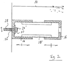
- Fig. 2 illustrates a tube 14 and an attachment 16, wherein the spacer 20 'has a milled thread. This thread can engage in a corresponding thread of the tube 14 and at the same time in a korrespondieredes thread of the attachment 16.
- the attachment 16 can be spatially removed in this way by rotating apart from the tube 14 and extend the overall length of the connecting piece 10.
- the tube 14 has a bore 26 through which a connecting screw 28 is guided.
- the diameter of the connecting screw 28 is less than the diameter of the bore 26, so that the position of the connecting screw 28 within the tube 14 to the substrate to which the tube 14 is to be arranged, is variably selectable. Within the bore 26, the connecting screw 28 can thus be adjusted so that the seat of the entire connector 10 is formed adaptable.
- the attachment 16 is shown cylindrically in this embodiment.
- the connecting screw 28 can be arranged by means of a nut 24 ', which can rest on a washer 30, on the ground.
Landscapes
- Physics & Mathematics (AREA)
- Engineering & Computer Science (AREA)
- Architecture (AREA)
- Acoustics & Sound (AREA)
- Electromagnetism (AREA)
- Civil Engineering (AREA)
- Structural Engineering (AREA)
- Joining Of Building Structures In Genera (AREA)
- Supports For Pipes And Cables (AREA)
Abstract
Description
- Die Erfindung betrifft ein Verbindungsstück zur Anordnung an einem Untergrund.
- Die Anordnung von Verankerungen an Mauerwerken, beispielsweise zur Anbringung von Anbauteilen wie Markisen, Balkonen, Wintergärten und Vordächern, ist in mehrerer Hinsicht problematisch, insbesondere, wenn das Mauerwerk eine Dämmung aufweist. Um eine stabile und sichere Verankerung zu gewährleisten ist es meist notwendig, die bestehende Dämmschicht zu entfernen und eine Konsole zu setzen, durch die dann die Verankerungen führen. Die Dämmschicht und der Putz müssen danach ausgebessert werden, was meist sehr aufwändig ist.
- Da eine Vielzahl von Gebäuden in gedämmter Ausführung vorliegen, müssen die Verbindungsanker bzw. -bolzen bestimmte Voraussetzungen erfüllen, damit weiterhin andere Bauteile mit dem Gebäude verbunden werden können, wobei insbesondere die vorhandene Wärmedämmung am Gebäude verbleiben kann. Die Anbringung an der Gebäudewand ist schwierig, da die geöffneten Wärmedämmelemente unterschiedliche Stärken aufweisen, so dass die Verbindungsanker häufig zu kurz oder zu lang sind und eine sichere Verbindung nicht gewährleisten, da die Wärmedämmelemente unterschiedlich dick bzw. stark ausgestaltet sind.
- Die
DE 23 15 859 A1 zeigt einen Verankerungsbolzen, der im eingesetzen Zustand einen aus der Mauer hervorragenden Gewindekopf aufweist. Am Schaft ist ein elastischer Textilstrumpf aufgezogen. Es ist eine zentrische Einspritzbohrung vorhanden und nahe dem Einführende radiale Öffnungen, die in den Raum zwischen Außenmantelfläche und Textilstrumpf öffnen. - Die genannten Erfordernisse zur Befestigung hält der Abstandshalter gemäß der genannten
DE 23 15 859 A1 nicht ein. Der vorhandene Abstand ist durch die Ausbildung in engen Grenzen festgelegt und nicht variabel. - Aufgabe der Erfindung ist es daher, ein Verbindungsstück zur Verfügung zu stellen, das an Untergründen von Bauelementen wie Mauerwerken von Gebäuden anordenbar und den jeweiligen Gegebenheiten anpassbar ist.
- Es wird ein Verbindungsstück zur Anordnung an einem Untergrund offenbart, das mehrteilig ausgebildet ist. Dieses Verbindungsstück weist mindestens zwei, üblicherweise drei Teile auf. Somit wird das Verbindungsstück an einem Untergrund bzw. Ansatzgrund, beispielsweise einer Wand, aufgebracht und weist dazu mindestens eine Tube und einen Aufsatz auf. Die Verbindung zwischen einer Gebäudewand oder einer Unterkonstruktion sowie dem Aufsatz und ggf. einem Anbauteil erfolgt über einen Verbindungsanker. Die Tube und der Aufsatz sind voneinander trennbar. Der Aufsatz kann mit dem Anbauteil verbunden werden.
- Innerhalb der Tube und dem Ansatzgrund ist in einem Ausführungsbeispiel in die jeweiligen Bestandteile eingreifend ein Distanzstück angeordnet. Entlang dieses Distanzstücks lässt sich der Aufsatz entlang schieben und somit der Abstand zwischen Boden und Aufsatzgrund verändern, insbesondere vergrößern. Somit wird ein in seiner Längserstreckung begrenzt verlängerbares Verbindungsstück erzielt.
- Dabei kann am Distanzstück sowie den inneren Öffnungen der Tube und des Aufsatz jeweils ein korrespondierendes Gewinde angeordnet sein, so dass die Teile zueinander durch Ineinandergreifen korrespondierend wirken und gegeneinander durch Auf- oder Zudrehen verstellbar ausgebildet sind. Zur besseren Funktionsweise der begrenzten Verstellbarkeit über das Gewinde können Futterelemente angeordnet werden.
- Das Distanzstück ist somit als Adapterstück ausgebildet. Üblicherweise besteht ein Bedarf an einer Vergrößerung des Abstands zur Anbringung von Anbauteilen zwischen diesen und der gedämmten Gebäudewand, so dass das Distanzstück als Verlängerungsmittel dient.
- Das Distanzstück kann abweichend auch außerhalb der Tube und des Aufsatzes angeordnet werden. Durch Verbinden mit der Tube und dem Aufsatz entsteht entsprechend ein begrenzt verlängerbares Distanzstück.
- In einer Mittelachse des Verbindungsstücks ist ein Verbindungsanker angeordnet, der die einzelnen Teile des Verbindungsstücks hält und ein Haltemittel für das Anbauteil bildet. Auf diesen Verbindungsanker wirken Zugkräfte ein. Die Druck- und Querkräfte werden durch die Tube in den Ansatzgrund, Unterfütterung, die Wand o.dgl., abgeleitet. In der zweiteiligen Ausbildung oben genannten Ausbildung, bei der eine Tube und ein Aufsatz ausgebildet sind, ist der Verbindungsanker das alleinige Verbindungsglied zwischen Tube und Aufsatz. Auf den Aufsatz wirken über den Angriff am Verbindungsanker auch Zugkräfte ein.
- Zur lösbaren oder irreversiblen Feststellung der einzelnen Bestandteile des Verbindungsstücks, nämlich der Tube und des Aufsatzes, die über das Distanzstück und die genannten Gewindeausführungen verbunden sind, sind Feststellmittel an der Tube und dem Aufsatz im Zusammenwirken mit den korrespondierenden Gewinden der Tube, des Aufsatzes sowie des Distanzstücks vorgesehen, beispielsweise Rastelemente, Lochbohrungen mit Splinden, ausgefräste Kanten, Nasen, Eingreifelemente o.dgl. Somit kann die Entfernung von Tube und Aufsatz voneinander bestimmt bzw. ggf. geändert werden. Je nach Bedarf kann der Abstand der beiden Teile, insbesondere abhängig von der Dicke einer Dämmschicht, verlängert bzw. angepasst werden.
- Bereits bei der Befestigung kann dabei die Länge des Verbindungsstücks festgelegt werden. Beispielsweise kann durch das Maß der Einschraubung, ein anschließendes Aufsetzen des Aufsatzes und Verriegeln eine festgelegte Länge des Verbindungsstücks erzielt werden.
- Das erfindungsgemäße Verbindungsstück hat dabei den Vorteil, dass mit einem einfachen funktionalen Aufbau unterschiedliche Abstände auf einfache Weise mit einem Bauteil abgedeckt werden können. Dies erleichtert die Anbringung von Anbauteilen an insbesondere wärmegedämmte Wänden o.dgl.
- Weitere Vorteile und vorteilhafte Ausgestaltungen der Erfindung sind der nachfolgenden Figurenbeschreibung, den Zeichnungen und den Ansprüchen entnehmbar.
- Nachfolgend wird ein Ausführungsbeispiel der erfindungsgemäßen Lösung anhand der beigefügten schematischen Zeichnungen näher erläutert. Es zeigt:
- Fig. 1
- zeigt einen Längsschnitt durch ein Verbindungsstück in einer dreiteiligen Ausbildung und
- Fig. 2
- zeigt einen Längsschnitt durch eine dreiteiligen Ausbildung, umfassend ein Gewinde.
- In
Fig. 1 ist ein Verbindungsstück 10 dargestellt. Das Verbindungsstück 10 ist an einem Untergrund 12 angeordnet. Das Verbindungsstück 10 weist eine Tube 14 sowie einen Aufsatz 16 auf. Die Skizzierung der offenen Tube 14 bzw. die Darstellung des schräg abgebildeten Querschnitts soll darstellen, dass die Tube 14 und der Aufsatz 16 mit kreisrundem Durchmesser in Zylinderform ausgebildet sein können und einen inneren Hohlraum aufweisen. Der Aufsatz 16 umfasst in diesem Ausführungsbeispiel eine deckelartige Ausbildung mit seitlich überstehenden Bereichen als Abschluss 18 an seiner dem Untergrund 12 distal entfernten Seite. - Jeweils an den Innenseiten der Tube 14 sowie des Aufsatzes 16 ist ein Distanzstück 20 angeordnet. Dieses Distanzstück 20 hat die Funktion eines Adapterstücks. Das Distanzstück 20 kann als Hülse ausgebildet sein. In diesem Ausführungsbeispiel können die Tube 14 und der Aufsatz 16 durch Hin- und Herbewegen bzw. zueinander oder weg voneinander-Bewegen des Aufsatzes 16 gegenüber der Tube 14 zueinander verstellt werden. Somit kann der Abstand dieser beiden Komponenten zueinander variiert werden. Damit können unterschiedliche Stärken bzw. Dicken beispielsweise eines Dämmmaterials ausgeglichen werden bzw. die Länge des Verbindungsstücks 10 kann an die jeweiligen Erfordernisse angepasst werden.
- Innerhalb des Verbindungsstücks 10 ist ein Verbindungsanker 22 angeordnet. Dieser dient der Verbindung des Aufsatzes 16 mit dem Untergrund 12. Dazu weist der Verbindungsanker 22 zur Verbindung mit dem Aufsatz 16 eine Mutter 24 auf. Es kann zur Verbesserung der Verbindung auch eine Unterlegscheibe angeordnet sein. An dem Aufsatz 16 kann das ausgewählte Anbauteil angeordnet werden.
- Die Entfernung der Tube 14 sowie des Aufsatzes 16 kann somit frei gewählt werden und den jeweiligen Anforderungen entsprechend angepasst werden. Zum Feststellen des ausgewählten Abstands können die jeweiligen Teile korrespondierend gefräst ausgebildet sein, so dass sie gegeneinander verstellbar ausgebildet sind, und die passende Entfernung dann durch Feststellmittel wie Rastelemente, Splinde in Löchern, Nasen, Kanten o.dgl. festgestellt werden.
-
Fig. 2 stellt eine Tube 14 sowie einen Aufsatz 16 dar, wobei das Distanzstück 20' ein eingefrästes Gewinde aufweist. Dieses Gewinde kann in ein korrespondierendes Gewinde der Tube 14 und gleichzeitig in ein korrespondieredes Gewinde des Aufsatzes 16 eingreifen. Der Aufsatz 16 kann auf diese Weise durch Auseinanderdrehen von der Tube 14 räumlich entfernt werden und die Gesamtlänge des Verbindungsstücks 10 verlängern. - Die Tube 14 weist eine Bohrung 26 auf, durch die eine Verbindungsschraube 28 geführt ist. Der Durchmesser der Verbindungsschraube 28 ist geringer als der Durchmesser der Bohrung 26, so dass die Lage der Verbindungsschraube 28 innerhalb der Tube 14 zum Untergrund, an dem die Tube 14 angeordnet werden soll, variabel wählbar ist. Innerhalb der Bohrung 26 kann die Verbindungsschraube 28 also so verstellt werden, dass der Sitz des gesamten Verbindungsstücks 10 anpassbar ausgebildet ist. Der Aufsatz 16 ist in diesem Ausführungsbeispiel zylindrisch dargestellt.
- Die Verbindungsschraube 28 kann mittels einer Mutter 24', die auf einer Unterlagscheibe 30 aufliegen kann, am Untergrund angeordnet werden.
- Alle in der Beschreibung, den nachfolgenden Ansprüchen und den Zeichnungen dargestellten Merkmale können sowohl einzeln als auch in beliebiger Kombination miteinander erfindungswesentlich sein.
-
- 10
- Verbindungsstück
- 12
- Untergrund
- 14
- Tube
- 16
- Aufsatz
- 18
- Abschluss
- 20
- Distanzstück
- 20'
- Distanzstück
- 22
- Verbindungsanker
- 24
- Mutter
- 24'
- Mutter
- 26
- Bohrung
- 28
- Verbindungsschraube
- 30
- Unterlegscheibe
Claims (12)
- Verbindungsstück (10) zur Anordnung an einem Untergrund (12), dadurch gekennzeichnet, dass das Verbindungsstück (10) mehrteilig ausgebildet ist und mindestens zwei zu- und voneinander weg bewegbare Teilstücke aufweist, so dass die Gesamtlänge des Verbindungsstücks (10) veränderbar ist, wobei das Verbindungsstück (10) eine Tube (14) sowie einen Aufsatz (16) aufweist und wobei das Verbindungsstück (10) ein Distanzstück (20, 20') umfasst, das an seinen jeweiligen Enden einerseits an der Tube (14) und andererseits an dem Aufsatz (16) angreift und der Aufsatz (16) entlang des Distanzstücks (20, 20') bewegbar angeordnet ist.
- Verbindungsstück (10) nach Anspruch 1, dadurch gekennzeichnet, dass der Abstand zwischen der Tube (14) und dem Aufsatz (16) durch Verschieben entlang des Distanzstücks (20, 20') zueinander oder weg voneinander veränderbar ist.
- Verbindungsstück (10) nach Anspruch 1, dadurch gekennzeichnet, das die Tube (14) und der Aufsatz (16) an ihren Seitenwänden jeweils ein Gewinde aufweisen und das Distanzstück (20, 20') an seinen Außen- oder Innenflächen ein korrespondierendes Gewinde aufweist, das in die Gewinde der Tube (14) und des Aufsatzes (16) eingreift und der Aufsatz (16) durch Drehen in der Längserstreckung in seiner Position veränderbar ist.
- Verbindungsstück (10) nach einem der Ansprüche 1 oder 3, dadurch gekennzeichnet, dass die Tube (14) und der Aufsatz (16) an den Außenflächen der Seitenwände jeweils ein Gewinde aufweisen und das Distanzstück (20, 20') an seinen Innenflächen ein korrespondierendes Gewinde aufweist, in das die Gewinde der Tube (14) und des Aufsatzes (16) eingreifen und der Aufsatz (16) durch Drehen in der Längserstreckung in seiner Position veränderbar ist.
- Verbindungsstück (10) nach einem der vorhergehenden Ansprüche, dadurch gekennzeichnet, dass die Tube (14) und/oder der Aufsatz (16) am Distanzstück (20, 20') feststellbar ist oder sind.
- Verbindungsstück (10) nach Anspruch 5, dadurch gekennzeichnet, dass die Feststellung der Tube (14) und/oder des Aufsatzes (16) über Rastelemente, Splinde in Löchern, Nasen, Verdrehsicherungen oder Kanten erfolgt.
- Verbindungsstück (10) nach einem der vorhergehenden Ansprüche 1, 3 bis 6, dadurch gekennzeichnet, dass das Distanzstück (20, 20') in die Tube (14) ein-oder auf die Tube (14) aufschraubbar und so feststellbar ist, so dass beim Eindrehen oder Aufsetzen des Aufsatzes (16) kein Mitdrehen des Distanzstücks (20, 20') erfolgt.
- Verbindungsstück (10) nach einem der vorhergehenden Ansprüche, dadurch gekennzeichnet, dass das Verbindungsstück (10) einen Verbindungsanker (22) aufweist, der als Festhaltemittel zwischen einem Untergrund (12) und dem Aufsatz (16) und/oder einem Anbauteil ausgebildet ist.
- Verbindungsstück (10) nach einem der vorhergehenden Ansprüche, dadurch gekennzeichnet, dass ein Verbindungsmittel (28) ausgebildet ist, das als Festhaltemittel zwischen einem Untergrund (12) und der Tube (14) ausgebildet ist.
- Verbindungsstück (10) nach einem der vorhergehenden Ansprüche, dadurch gekennzeichnet, dass auf das Distanzstück (20, 20') und die Tube (14) Druckkräfte einwirken und auf das Verbindungsmittel (22, 28) und den Aufsatz (16) Zug- und -Querkräfte einwirken, so dass das Distanzstück (20, 20') und die Tube (14) in Verbindung mit dem Verbindungsmittel (22, 28) und dem Aufsatz (16) mindestens ein Kräftepaar ausbilden.
- Verbindungsstück (10) nach Anspruch 10, dadurch gekennzeichnet, dass das Distanzstück (20, 20') und die Tube (14) sowie der Aufsatz (16) so ausgebildet sind, dass sie mindestens ein Kräftepaar aus Zug und Druck und somit Momente aufnehmen.
- Verbindungsstück (10) nach einem der vorhergehenden Ansprüche, dadurch gekennzeichnet, dass das Verbindungsmittel (22, 28) in einer Öffnung (26) geführt ist und der Durchmesser des Verbindungsmittels (22, 28) kleiner als der Durchmesser der Öffnung (26) ausgebildet ist, so dass das Verbindungsmittel ( 22, 28) innerhalb der Öffnung (26) begrenzt verstellbar gelagert ist.
Priority Applications (2)
| Application Number | Priority Date | Filing Date | Title |
|---|---|---|---|
| EP17000070.7A EP3348724B1 (de) | 2017-01-14 | 2017-01-14 | Verbindungsstück |
| DK17000070T DK3348724T3 (da) | 2017-01-14 | 2017-01-14 | Forbindelsesstykke |
Applications Claiming Priority (1)
| Application Number | Priority Date | Filing Date | Title |
|---|---|---|---|
| EP17000070.7A EP3348724B1 (de) | 2017-01-14 | 2017-01-14 | Verbindungsstück |
Publications (2)
| Publication Number | Publication Date |
|---|---|
| EP3348724A1 true EP3348724A1 (de) | 2018-07-18 |
| EP3348724B1 EP3348724B1 (de) | 2019-10-16 |
Family
ID=57868013
Family Applications (1)
| Application Number | Title | Priority Date | Filing Date |
|---|---|---|---|
| EP17000070.7A Active EP3348724B1 (de) | 2017-01-14 | 2017-01-14 | Verbindungsstück |
Country Status (2)
| Country | Link |
|---|---|
| EP (1) | EP3348724B1 (de) |
| DK (1) | DK3348724T3 (de) |
Citations (4)
| Publication number | Priority date | Publication date | Assignee | Title |
|---|---|---|---|---|
| DE2315859A1 (de) | 1973-03-30 | 1974-10-03 | Alfons Harke | Verankerungsbolzen |
| DE29805143U1 (de) * | 1998-03-23 | 1998-07-16 | Nicolai, Karl-Friedrich, 24146 Kiel | Balkonanlage mit einem Gebäudeanschluß |
| EP2278173A2 (de) * | 2009-06-26 | 2011-01-26 | Ing. Alois Mitterhuber GesmbH | Befestigungsmittel zur Anbringung von Außenelementen auf einer mit einer Außenwandisollierung versehenen festen Wand |
| FR2954374A1 (fr) * | 2009-12-23 | 2011-06-24 | Bugal | Dispositif de soutien d'une structure, par exemple une plateforme, telle que balcon ou terrasse |
Family Cites Families (2)
| Publication number | Priority date | Publication date | Assignee | Title |
|---|---|---|---|---|
| EP3426855A1 (de) * | 2016-03-10 | 2019-01-16 | Giller, Jutta | Abstandshalter und befestiger für durch eine fassade hindurch am gebäude zu befestigenden teile |
| EP3336271B1 (de) * | 2016-12-13 | 2019-10-23 | Armand Joseph Lang | Befestigungsvorrichtung zur befestigung eines bauelements an einem eine dämmschicht aufweisenden bauteil |
-
2017
- 2017-01-14 DK DK17000070T patent/DK3348724T3/da active
- 2017-01-14 EP EP17000070.7A patent/EP3348724B1/de active Active
Patent Citations (4)
| Publication number | Priority date | Publication date | Assignee | Title |
|---|---|---|---|---|
| DE2315859A1 (de) | 1973-03-30 | 1974-10-03 | Alfons Harke | Verankerungsbolzen |
| DE29805143U1 (de) * | 1998-03-23 | 1998-07-16 | Nicolai, Karl-Friedrich, 24146 Kiel | Balkonanlage mit einem Gebäudeanschluß |
| EP2278173A2 (de) * | 2009-06-26 | 2011-01-26 | Ing. Alois Mitterhuber GesmbH | Befestigungsmittel zur Anbringung von Außenelementen auf einer mit einer Außenwandisollierung versehenen festen Wand |
| FR2954374A1 (fr) * | 2009-12-23 | 2011-06-24 | Bugal | Dispositif de soutien d'une structure, par exemple une plateforme, telle que balcon ou terrasse |
Also Published As
| Publication number | Publication date |
|---|---|
| EP3348724B1 (de) | 2019-10-16 |
| DK3348724T3 (da) | 2019-12-02 |
Similar Documents
| Publication | Publication Date | Title |
|---|---|---|
| EP2309138B1 (de) | Spreizdübel | |
| DE102007016236B3 (de) | Abstandshalter zur Befestigung eines Halteelementes in einer Wandung | |
| EP2666919B1 (de) | Verfahren und Befestigungssystem zum Anbringen von Dämmstoffplatten an einem Untergrund | |
| EP2068007A2 (de) | Verfahren und Befestigungssystem zum Anbringen von Dämmstoffplatten sowie einen Dübel und einen Halteteller | |
| EP2821559B1 (de) | Abstandshalter | |
| DE202009004831U1 (de) | Bauwerkanker sowie Bauwerkankersystem | |
| EP2354448A2 (de) | Selbstbohranker mit Bohrankerdichtung | |
| EP2215317B2 (de) | Dämmstoffhalter und verfahren zum befestigen einer dämmstoffplatte | |
| AT510315B1 (de) | Anordnung zur, insbesondere distanzierten, befestigung zumindest einer dämmstoffplatte an einem gebäude | |
| DE202011100848U1 (de) | Gerüstverankerungsvorrichtung | |
| DE202010012930U1 (de) | Bauwerkanker | |
| DE102011010526A1 (de) | Hinterschnittanker | |
| DE4112128A1 (de) | Verfahren und injektionsanker zum sanieren von doppelschaligen gebaeudewaenden | |
| DE102017000318A1 (de) | Verbindungsstück | |
| EP3348743B1 (de) | Verbindungssystem zur verbindung von bauelementen | |
| EP3348724B1 (de) | Verbindungsstück | |
| DE102004014905B3 (de) | Kipp- und drehsichere Monumentbefestigung, insbesondere Grabmalbefestigung | |
| EP3473779A1 (de) | Verbindungselement mit feststellelement sowie verfahren zum feststellen des verbindungselements | |
| DE102017000320A1 (de) | Überbrückungselement zur Verbindung von Bauelementen | |
| EP1970575A2 (de) | Spreizdübel für zweischaliges Mauerwerk | |
| DE102004052184A1 (de) | Nageldübel | |
| DE102016000088A1 (de) | Schraubanker | |
| EP3348723B1 (de) | Überbrückungselement zur verbindung von bauelementen | |
| DE102008053638A1 (de) | Vorrichtung zum Justieren eines Bauelementes in einem Abstand zum Bauteil | |
| DE202014005249U1 (de) | Spreizanker |
Legal Events
| Date | Code | Title | Description |
|---|---|---|---|
| PUAI | Public reference made under article 153(3) epc to a published international application that has entered the european phase |
Free format text: ORIGINAL CODE: 0009012 |
|
| STAA | Information on the status of an ep patent application or granted ep patent |
Free format text: STATUS: REQUEST FOR EXAMINATION WAS MADE |
|
| 17P | Request for examination filed |
Effective date: 20180409 |
|
| AK | Designated contracting states |
Kind code of ref document: A1 Designated state(s): AL AT BE BG CH CY CZ DE DK EE ES FI FR GB GR HR HU IE IS IT LI LT LU LV MC MK MT NL NO PL PT RO RS SE SI SK SM TR |
|
| AX | Request for extension of the european patent |
Extension state: BA ME |
|
| STAA | Information on the status of an ep patent application or granted ep patent |
Free format text: STATUS: EXAMINATION IS IN PROGRESS |
|
| 17Q | First examination report despatched |
Effective date: 20181105 |
|
| GRAP | Despatch of communication of intention to grant a patent |
Free format text: ORIGINAL CODE: EPIDOSNIGR1 |
|
| STAA | Information on the status of an ep patent application or granted ep patent |
Free format text: STATUS: GRANT OF PATENT IS INTENDED |
|
| INTG | Intention to grant announced |
Effective date: 20190710 |
|
| GRAS | Grant fee paid |
Free format text: ORIGINAL CODE: EPIDOSNIGR3 |
|
| GRAA | (expected) grant |
Free format text: ORIGINAL CODE: 0009210 |
|
| STAA | Information on the status of an ep patent application or granted ep patent |
Free format text: STATUS: THE PATENT HAS BEEN GRANTED |
|
| AK | Designated contracting states |
Kind code of ref document: B1 Designated state(s): AL AT BE BG CH CY CZ DE DK EE ES FI FR GB GR HR HU IE IS IT LI LT LU LV MC MK MT NL NO PL PT RO RS SE SI SK SM TR |
|
| REG | Reference to a national code |
Ref country code: GB Ref legal event code: FG4D Free format text: NOT ENGLISH |
|
| REG | Reference to a national code |
Ref country code: CH Ref legal event code: EP |
|
| REG | Reference to a national code |
Ref country code: DE Ref legal event code: R096 Ref document number: 502017002542 Country of ref document: DE |
|
| REG | Reference to a national code |
Ref country code: IE Ref legal event code: FG4D Free format text: LANGUAGE OF EP DOCUMENT: GERMAN |
|
| REG | Reference to a national code |
Ref country code: AT Ref legal event code: REF Ref document number: 1191384 Country of ref document: AT Kind code of ref document: T Effective date: 20191115 |
|
| REG | Reference to a national code |
Ref country code: CH Ref legal event code: NV Representative=s name: RENTSCH PARTNER AG, CH |
|
| REG | Reference to a national code |
Ref country code: DK Ref legal event code: T3 Effective date: 20191125 |
|
| REG | Reference to a national code |
Ref country code: SE Ref legal event code: TRGR |
|
| REG | Reference to a national code |
Ref country code: NL Ref legal event code: FP |
|
| REG | Reference to a national code |
Ref country code: NO Ref legal event code: T2 Effective date: 20191016 |
|
| REG | Reference to a national code |
Ref country code: LT Ref legal event code: MG4D |
|
| PG25 | Lapsed in a contracting state [announced via postgrant information from national office to epo] |
Ref country code: BG Free format text: LAPSE BECAUSE OF FAILURE TO SUBMIT A TRANSLATION OF THE DESCRIPTION OR TO PAY THE FEE WITHIN THE PRESCRIBED TIME-LIMIT Effective date: 20200116 Ref country code: PT Free format text: LAPSE BECAUSE OF FAILURE TO SUBMIT A TRANSLATION OF THE DESCRIPTION OR TO PAY THE FEE WITHIN THE PRESCRIBED TIME-LIMIT Effective date: 20200217 Ref country code: PL Free format text: LAPSE BECAUSE OF FAILURE TO SUBMIT A TRANSLATION OF THE DESCRIPTION OR TO PAY THE FEE WITHIN THE PRESCRIBED TIME-LIMIT Effective date: 20191016 Ref country code: LV Free format text: LAPSE BECAUSE OF FAILURE TO SUBMIT A TRANSLATION OF THE DESCRIPTION OR TO PAY THE FEE WITHIN THE PRESCRIBED TIME-LIMIT Effective date: 20191016 Ref country code: GR Free format text: LAPSE BECAUSE OF FAILURE TO SUBMIT A TRANSLATION OF THE DESCRIPTION OR TO PAY THE FEE WITHIN THE PRESCRIBED TIME-LIMIT Effective date: 20200117 Ref country code: LT Free format text: LAPSE BECAUSE OF FAILURE TO SUBMIT A TRANSLATION OF THE DESCRIPTION OR TO PAY THE FEE WITHIN THE PRESCRIBED TIME-LIMIT Effective date: 20191016 |
|
| PG25 | Lapsed in a contracting state [announced via postgrant information from national office to epo] |
Ref country code: HR Free format text: LAPSE BECAUSE OF FAILURE TO SUBMIT A TRANSLATION OF THE DESCRIPTION OR TO PAY THE FEE WITHIN THE PRESCRIBED TIME-LIMIT Effective date: 20191016 Ref country code: RS Free format text: LAPSE BECAUSE OF FAILURE TO SUBMIT A TRANSLATION OF THE DESCRIPTION OR TO PAY THE FEE WITHIN THE PRESCRIBED TIME-LIMIT Effective date: 20191016 Ref country code: IS Free format text: LAPSE BECAUSE OF FAILURE TO SUBMIT A TRANSLATION OF THE DESCRIPTION OR TO PAY THE FEE WITHIN THE PRESCRIBED TIME-LIMIT Effective date: 20200224 |
|
| PG25 | Lapsed in a contracting state [announced via postgrant information from national office to epo] |
Ref country code: AL Free format text: LAPSE BECAUSE OF FAILURE TO SUBMIT A TRANSLATION OF THE DESCRIPTION OR TO PAY THE FEE WITHIN THE PRESCRIBED TIME-LIMIT Effective date: 20191016 |
|
| REG | Reference to a national code |
Ref country code: DE Ref legal event code: R097 Ref document number: 502017002542 Country of ref document: DE |
|
| PG2D | Information on lapse in contracting state deleted |
Ref country code: IS |
|
| PG25 | Lapsed in a contracting state [announced via postgrant information from national office to epo] |
Ref country code: EE Free format text: LAPSE BECAUSE OF FAILURE TO SUBMIT A TRANSLATION OF THE DESCRIPTION OR TO PAY THE FEE WITHIN THE PRESCRIBED TIME-LIMIT Effective date: 20191016 Ref country code: ES Free format text: LAPSE BECAUSE OF FAILURE TO SUBMIT A TRANSLATION OF THE DESCRIPTION OR TO PAY THE FEE WITHIN THE PRESCRIBED TIME-LIMIT Effective date: 20191016 Ref country code: RO Free format text: LAPSE BECAUSE OF FAILURE TO SUBMIT A TRANSLATION OF THE DESCRIPTION OR TO PAY THE FEE WITHIN THE PRESCRIBED TIME-LIMIT Effective date: 20191016 Ref country code: CZ Free format text: LAPSE BECAUSE OF FAILURE TO SUBMIT A TRANSLATION OF THE DESCRIPTION OR TO PAY THE FEE WITHIN THE PRESCRIBED TIME-LIMIT Effective date: 20191016 Ref country code: IS Free format text: LAPSE BECAUSE OF FAILURE TO SUBMIT A TRANSLATION OF THE DESCRIPTION OR TO PAY THE FEE WITHIN THE PRESCRIBED TIME-LIMIT Effective date: 20200216 |
|
| PLBE | No opposition filed within time limit |
Free format text: ORIGINAL CODE: 0009261 |
|
| STAA | Information on the status of an ep patent application or granted ep patent |
Free format text: STATUS: NO OPPOSITION FILED WITHIN TIME LIMIT |
|
| PG25 | Lapsed in a contracting state [announced via postgrant information from national office to epo] |
Ref country code: SM Free format text: LAPSE BECAUSE OF FAILURE TO SUBMIT A TRANSLATION OF THE DESCRIPTION OR TO PAY THE FEE WITHIN THE PRESCRIBED TIME-LIMIT Effective date: 20191016 Ref country code: IT Free format text: LAPSE BECAUSE OF FAILURE TO SUBMIT A TRANSLATION OF THE DESCRIPTION OR TO PAY THE FEE WITHIN THE PRESCRIBED TIME-LIMIT Effective date: 20191016 Ref country code: MC Free format text: LAPSE BECAUSE OF FAILURE TO SUBMIT A TRANSLATION OF THE DESCRIPTION OR TO PAY THE FEE WITHIN THE PRESCRIBED TIME-LIMIT Effective date: 20191016 Ref country code: SK Free format text: LAPSE BECAUSE OF FAILURE TO SUBMIT A TRANSLATION OF THE DESCRIPTION OR TO PAY THE FEE WITHIN THE PRESCRIBED TIME-LIMIT Effective date: 20191016 |
|
| 26N | No opposition filed |
Effective date: 20200717 |
|
| PG25 | Lapsed in a contracting state [announced via postgrant information from national office to epo] |
Ref country code: LU Free format text: LAPSE BECAUSE OF NON-PAYMENT OF DUE FEES Effective date: 20200114 |
|
| PG25 | Lapsed in a contracting state [announced via postgrant information from national office to epo] |
Ref country code: SI Free format text: LAPSE BECAUSE OF FAILURE TO SUBMIT A TRANSLATION OF THE DESCRIPTION OR TO PAY THE FEE WITHIN THE PRESCRIBED TIME-LIMIT Effective date: 20191016 |
|
| PG25 | Lapsed in a contracting state [announced via postgrant information from national office to epo] |
Ref country code: IE Free format text: LAPSE BECAUSE OF NON-PAYMENT OF DUE FEES Effective date: 20200114 |
|
| PGFP | Annual fee paid to national office [announced via postgrant information from national office to epo] |
Ref country code: FI Payment date: 20220119 Year of fee payment: 6 |
|
| PG25 | Lapsed in a contracting state [announced via postgrant information from national office to epo] |
Ref country code: TR Free format text: LAPSE BECAUSE OF FAILURE TO SUBMIT A TRANSLATION OF THE DESCRIPTION OR TO PAY THE FEE WITHIN THE PRESCRIBED TIME-LIMIT Effective date: 20191016 Ref country code: MT Free format text: LAPSE BECAUSE OF FAILURE TO SUBMIT A TRANSLATION OF THE DESCRIPTION OR TO PAY THE FEE WITHIN THE PRESCRIBED TIME-LIMIT Effective date: 20191016 Ref country code: CY Free format text: LAPSE BECAUSE OF FAILURE TO SUBMIT A TRANSLATION OF THE DESCRIPTION OR TO PAY THE FEE WITHIN THE PRESCRIBED TIME-LIMIT Effective date: 20191016 |
|
| PGFP | Annual fee paid to national office [announced via postgrant information from national office to epo] |
Ref country code: NO Payment date: 20220121 Year of fee payment: 6 |
|
| PG25 | Lapsed in a contracting state [announced via postgrant information from national office to epo] |
Ref country code: MK Free format text: LAPSE BECAUSE OF FAILURE TO SUBMIT A TRANSLATION OF THE DESCRIPTION OR TO PAY THE FEE WITHIN THE PRESCRIBED TIME-LIMIT Effective date: 20191016 |
|
| PGFP | Annual fee paid to national office [announced via postgrant information from national office to epo] |
Ref country code: SE Payment date: 20230123 Year of fee payment: 7 |
|
| REG | Reference to a national code |
Ref country code: NO Ref legal event code: MMEP |
|
| PG25 | Lapsed in a contracting state [announced via postgrant information from national office to epo] |
Ref country code: NO Free format text: LAPSE BECAUSE OF NON-PAYMENT OF DUE FEES Effective date: 20230131 Ref country code: FI Free format text: LAPSE BECAUSE OF NON-PAYMENT OF DUE FEES Effective date: 20230114 |
|
| PGFP | Annual fee paid to national office [announced via postgrant information from national office to epo] |
Ref country code: DK Payment date: 20240123 Year of fee payment: 8 |
|
| REG | Reference to a national code |
Ref country code: SE Ref legal event code: EUG |
|
| PGFP | Annual fee paid to national office [announced via postgrant information from national office to epo] |
Ref country code: NL Payment date: 20250122 Year of fee payment: 9 |
|
| PGFP | Annual fee paid to national office [announced via postgrant information from national office to epo] |
Ref country code: DE Payment date: 20250120 Year of fee payment: 9 |
|
| PGFP | Annual fee paid to national office [announced via postgrant information from national office to epo] |
Ref country code: CH Payment date: 20250201 Year of fee payment: 9 Ref country code: AT Payment date: 20250120 Year of fee payment: 9 Ref country code: BE Payment date: 20250121 Year of fee payment: 9 |
|
| PGFP | Annual fee paid to national office [announced via postgrant information from national office to epo] |
Ref country code: FR Payment date: 20250123 Year of fee payment: 9 |
|
| PGFP | Annual fee paid to national office [announced via postgrant information from national office to epo] |
Ref country code: GB Payment date: 20250123 Year of fee payment: 9 |
|
| REG | Reference to a national code |
Ref country code: DK Ref legal event code: EBP Effective date: 20250131 |
|
| PG25 | Lapsed in a contracting state [announced via postgrant information from national office to epo] |
Ref country code: SE Free format text: LAPSE BECAUSE OF NON-PAYMENT OF DUE FEES Effective date: 20240115 |
|
| PG25 | Lapsed in a contracting state [announced via postgrant information from national office to epo] |
Ref country code: DK Free format text: LAPSE BECAUSE OF NON-PAYMENT OF DUE FEES Effective date: 20250131 |