EP3348422A1 - Pneumatique destiné à un véhicule de tourisme - Google Patents
Pneumatique destiné à un véhicule de tourisme Download PDFInfo
- Publication number
- EP3348422A1 EP3348422A1 EP16843880.2A EP16843880A EP3348422A1 EP 3348422 A1 EP3348422 A1 EP 3348422A1 EP 16843880 A EP16843880 A EP 16843880A EP 3348422 A1 EP3348422 A1 EP 3348422A1
- Authority
- EP
- European Patent Office
- Prior art keywords
- tire
- rubber
- tread
- sipe
- circumferential
- Prior art date
- Legal status (The legal status is an assumption and is not a legal conclusion. Google has not performed a legal analysis and makes no representation as to the accuracy of the status listed.)
- Withdrawn
Links
Images


Classifications
-
- B—PERFORMING OPERATIONS; TRANSPORTING
- B60—VEHICLES IN GENERAL
- B60C—VEHICLE TYRES; TYRE INFLATION; TYRE CHANGING; CONNECTING VALVES TO INFLATABLE ELASTIC BODIES IN GENERAL; DEVICES OR ARRANGEMENTS RELATED TO TYRES
- B60C1/00—Tyres characterised by the chemical composition or the physical arrangement or mixture of the composition
- B60C1/0016—Compositions of the tread
-
- B—PERFORMING OPERATIONS; TRANSPORTING
- B60—VEHICLES IN GENERAL
- B60C—VEHICLE TYRES; TYRE INFLATION; TYRE CHANGING; CONNECTING VALVES TO INFLATABLE ELASTIC BODIES IN GENERAL; DEVICES OR ARRANGEMENTS RELATED TO TYRES
- B60C11/00—Tyre tread bands; Tread patterns; Anti-skid inserts
- B60C11/0008—Tyre tread bands; Tread patterns; Anti-skid inserts characterised by the tread rubber
-
- B—PERFORMING OPERATIONS; TRANSPORTING
- B60—VEHICLES IN GENERAL
- B60C—VEHICLE TYRES; TYRE INFLATION; TYRE CHANGING; CONNECTING VALVES TO INFLATABLE ELASTIC BODIES IN GENERAL; DEVICES OR ARRANGEMENTS RELATED TO TYRES
- B60C11/00—Tyre tread bands; Tread patterns; Anti-skid inserts
- B60C11/03—Tread patterns
- B60C11/12—Tread patterns characterised by the use of narrow slits or incisions, e.g. sipes
- B60C11/1204—Tread patterns characterised by the use of narrow slits or incisions, e.g. sipes with special shape of the sipe
-
- B—PERFORMING OPERATIONS; TRANSPORTING
- B60—VEHICLES IN GENERAL
- B60C—VEHICLE TYRES; TYRE INFLATION; TYRE CHANGING; CONNECTING VALVES TO INFLATABLE ELASTIC BODIES IN GENERAL; DEVICES OR ARRANGEMENTS RELATED TO TYRES
- B60C11/00—Tyre tread bands; Tread patterns; Anti-skid inserts
- B60C11/03—Tread patterns
- B60C11/12—Tread patterns characterised by the use of narrow slits or incisions, e.g. sipes
- B60C11/1236—Tread patterns characterised by the use of narrow slits or incisions, e.g. sipes with special arrangements in the tread pattern
-
- B—PERFORMING OPERATIONS; TRANSPORTING
- B60—VEHICLES IN GENERAL
- B60C—VEHICLE TYRES; TYRE INFLATION; TYRE CHANGING; CONNECTING VALVES TO INFLATABLE ELASTIC BODIES IN GENERAL; DEVICES OR ARRANGEMENTS RELATED TO TYRES
- B60C3/00—Tyres characterised by the transverse section
- B60C3/04—Tyres characterised by the transverse section characterised by the relative dimensions of the section, e.g. low profile
-
- C—CHEMISTRY; METALLURGY
- C08—ORGANIC MACROMOLECULAR COMPOUNDS; THEIR PREPARATION OR CHEMICAL WORKING-UP; COMPOSITIONS BASED THEREON
- C08K—Use of inorganic or non-macromolecular organic substances as compounding ingredients
- C08K5/00—Use of organic ingredients
- C08K5/01—Hydrocarbons
-
- C—CHEMISTRY; METALLURGY
- C08—ORGANIC MACROMOLECULAR COMPOUNDS; THEIR PREPARATION OR CHEMICAL WORKING-UP; COMPOSITIONS BASED THEREON
- C08L—COMPOSITIONS OF MACROMOLECULAR COMPOUNDS
- C08L7/00—Compositions of natural rubber
-
- C—CHEMISTRY; METALLURGY
- C08—ORGANIC MACROMOLECULAR COMPOUNDS; THEIR PREPARATION OR CHEMICAL WORKING-UP; COMPOSITIONS BASED THEREON
- C08L—COMPOSITIONS OF MACROMOLECULAR COMPOUNDS
- C08L9/00—Compositions of homopolymers or copolymers of conjugated diene hydrocarbons
- C08L9/06—Copolymers with styrene
-
- B—PERFORMING OPERATIONS; TRANSPORTING
- B60—VEHICLES IN GENERAL
- B60C—VEHICLE TYRES; TYRE INFLATION; TYRE CHANGING; CONNECTING VALVES TO INFLATABLE ELASTIC BODIES IN GENERAL; DEVICES OR ARRANGEMENTS RELATED TO TYRES
- B60C11/00—Tyre tread bands; Tread patterns; Anti-skid inserts
- B60C11/0008—Tyre tread bands; Tread patterns; Anti-skid inserts characterised by the tread rubber
- B60C2011/0016—Physical properties or dimensions
- B60C2011/0025—Modulus or tan delta
-
- B—PERFORMING OPERATIONS; TRANSPORTING
- B60—VEHICLES IN GENERAL
- B60C—VEHICLE TYRES; TYRE INFLATION; TYRE CHANGING; CONNECTING VALVES TO INFLATABLE ELASTIC BODIES IN GENERAL; DEVICES OR ARRANGEMENTS RELATED TO TYRES
- B60C11/00—Tyre tread bands; Tread patterns; Anti-skid inserts
- B60C11/03—Tread patterns
- B60C2011/0337—Tread patterns characterised by particular design features of the pattern
- B60C2011/0339—Grooves
- B60C2011/0341—Circumferential grooves
-
- B—PERFORMING OPERATIONS; TRANSPORTING
- B60—VEHICLES IN GENERAL
- B60C—VEHICLE TYRES; TYRE INFLATION; TYRE CHANGING; CONNECTING VALVES TO INFLATABLE ELASTIC BODIES IN GENERAL; DEVICES OR ARRANGEMENTS RELATED TO TYRES
- B60C11/00—Tyre tread bands; Tread patterns; Anti-skid inserts
- B60C11/03—Tread patterns
- B60C11/12—Tread patterns characterised by the use of narrow slits or incisions, e.g. sipes
- B60C11/1204—Tread patterns characterised by the use of narrow slits or incisions, e.g. sipes with special shape of the sipe
- B60C2011/1209—Tread patterns characterised by the use of narrow slits or incisions, e.g. sipes with special shape of the sipe straight at the tread surface
-
- B—PERFORMING OPERATIONS; TRANSPORTING
- B60—VEHICLES IN GENERAL
- B60C—VEHICLE TYRES; TYRE INFLATION; TYRE CHANGING; CONNECTING VALVES TO INFLATABLE ELASTIC BODIES IN GENERAL; DEVICES OR ARRANGEMENTS RELATED TO TYRES
- B60C11/00—Tyre tread bands; Tread patterns; Anti-skid inserts
- B60C11/03—Tread patterns
- B60C11/12—Tread patterns characterised by the use of narrow slits or incisions, e.g. sipes
- B60C11/1236—Tread patterns characterised by the use of narrow slits or incisions, e.g. sipes with special arrangements in the tread pattern
- B60C2011/1254—Tread patterns characterised by the use of narrow slits or incisions, e.g. sipes with special arrangements in the tread pattern with closed sipe, i.e. not extending to a groove
-
- B—PERFORMING OPERATIONS; TRANSPORTING
- B60—VEHICLES IN GENERAL
- B60C—VEHICLE TYRES; TYRE INFLATION; TYRE CHANGING; CONNECTING VALVES TO INFLATABLE ELASTIC BODIES IN GENERAL; DEVICES OR ARRANGEMENTS RELATED TO TYRES
- B60C2200/00—Tyres specially adapted for particular applications
- B60C2200/04—Tyres specially adapted for particular applications for road vehicles, e.g. passenger cars
Definitions
- the present disclosure relates to a passenger vehicle pneumatic tire.
- a passenger vehicle pneumatic tire is a passenger vehicle pneumatic tire comprising: a carcass composed of a carcass ply of a radially arranged cord toroidally extending between a pair of bead portions; and a tread rubber provided on a tire radial outer side of the carcass, wherein when the tire is attached to a rim and applied with an internal pressure of 250 kPa or more, a ratio SW/OD between a sectional width SW and an outer diameter OD in mm of the tire is 0.26 or less in the case where the sectional width SW of the tire is less than 165 mm, and the sectional width SW and the outer diameter OD in mm of the tire satisfy a relational expression: 2.135 ⁇ SW + 282.3 ⁇ OD in the case where the sectional width SW of the tire is 165 mm or more, and at least part of a portion of the tread rubber located at a tread rubber surface has a dynamic storage modulus E' of 4.0 MPa or more at a dynamic strain of
- the passenger vehicle pneumatic tire according to the present disclosure has sufficiently improved wet performance.
- the sectional width SW and outer diameter OD of the tire are respectively the sectional width and outer diameter defined in JIS D 4202-1994, in a state where the tire is attached to a rim and applied with an internal pressure of 250 kPa or more.
- the "rim” is an approved rim ("measuring rim” in ETRTO Standards Manual, "design rim” in TRA Year Book) in applicable size that is described or will be described in the future in an effective industrial standard in areas where tires are produced or used, such as JATMA (Japan Automobile Tyre Manufacturers Association) Year Book in Japan, ETRTO (European Tyre and Rim Technical Organisation) Standards Manual in Europe, or TRA (Tire and Rim Association, Inc.) Year Book in the United States (the “rim” includes not only current size but also a size that may be included in the industrial standard in the future, and an example of the "size that will be described in the future” is the size described as "future developments" in ETRTO Standards Manual 2013). In the case of a size not described in the industrial standard, the "rim” refers to a rim whose width corresponds to the bead width of the tire.
- the dynamic storage modulus E' at a dynamic strain of 1% and 30°C is a value (MPa) measured for vulcanized rubber by applying an initial load of 160 g to a test piece of 2 mm in thickness, 5 mm in width, and 20 mm in length, under the conditions of a dynamic strain of 1% and a vibration frequency of 50 Hz.
- the dynamic storage modulus E' is a value measured at a dynamic strain of 1% and a temperature of 30°C, unless otherwise stated (hereafter dynamic storage modulus E' is also simply referred to as "E' ").
- the tread rubber means rubber that does not include members such as belts optionally included in the tread.
- the passenger vehicle pneumatic tire according to the present disclosure comprises, in a tread surface, at least one rib-like land portion defined by a tread ground contact edge and a circumferential main groove continuously extending in a tire circumferential direction or by two circumferential main grooves continuously extending in the tire circumferential direction and adjacent to each other.
- the "rib-like land portion” is a land portion in which the below-mentioned groove that has both ends open to the circumferential main grooves or the circumferential main groove and the tread ground contact edge defining the land portion and cuts across the land portion is not provided.
- the rib-like land portion has no both-end open sipe having both ends open to the tread ground contact edge and the circumferential main groove or to the two circumferential main grooves, and has a one-end open sipe having one end open to one of the tread ground contact edge and the circumferential main groove or to one of the two circumferential main grooves and the other end terminating within the rib-like land portion.
- the "sipe” refers to that whose opening width to the tread surface is 1.5 mm or less, in a state where the tire is attached to a rim, applied with an internal pressure of 30 kPa which is such a pressure that maintains the tire shape, and placed under no load (hereafter, the "state where the tire is attached to a rim, applied with an internal pressure of 30 kPa which is such a pressure that maintains the tire shape, and placed under no load” is also referred to as "low-pressure no-load state”).
- the “groove” refers to that whose opening width to the tread surface is more than 1.5 mm in the low-pressure no-load state.
- each element of the tread surface is measured in a developed view of the tread surface in the low-pressure no-load state, unless otherwise stated.
- the one-end open sipe includes: a circumferential sipe portion extending from the other end in the tire circumferential direction; and a widthwise sipe portion extending from the circumferential sipe portion in a tire width direction and open to the circumferential main groove or the tread ground contact edge.
- the rib-like land portion has a both-end closed sipe having both ends terminating within the rib-like land portion.
- a passenger vehicle pneumatic tire 1 includes at least: a carcass 22 composed of one or more carcass plies of radially arranged cords toroidally extending between a pair of bead portions 21; and a tread rubber 23 provided on the tire radial outer side of the carcass 22, as illustrated in FIG. 1 .
- the tire 1 includes: a tread portion 24; a pair of sidewall portions 25 continuously extending from the sides of the tread portion 24 inward in the tire radial direction; the bead portions 21 continuous from the tire radial inner ends of the respective sidewall portions 25; and the carcass 22 composed of one or more carcass plies toroidally extending between the pair of bead portions 21 and reinforcing each portion.
- a bead core is buried in each bead portion 21.
- a rubber chafer is provided on the outer surface of each bead portion 21, as a reinforcement member of the bead portion 21.
- a belt 26 composed of one or more belt layers is provided in the crown portion of the carcass 22.
- the tread rubber 23 is located on the tire radial outer side of the crown portion of the carcass 22.
- the ratio SW/OD between the sectional width SW (mm) and outer diameter OD (mm) of the tire 1 is 0.26 or less in the case where the sectional width SW of the tire 1 is less than 165 (mm), and the sectional width SW (mm) and outer diameter OD (mm) of the tire 1 satisfy the relationship: 2.135 ⁇ SW + 282.3 ⁇ OD in the case where the sectional width SW of the tire 1 is 165 (mm) or more (the tire size in this relationship is hereafter also referred to as "narrow-width, large-diameter size").
- the tire 1 satisfying this relationship has a narrow-width, large-diameter shape.
- the tire 1 can be improved in rolling resistance performance (reduced in rolling resistance coefficient), and reduced in weight.
- the internal pressure during rolling of the tire 1 is preferably 250 kPa or more, and more preferably 250 to 350 kPa.
- the ground contact length tends to increase. Limiting the internal pressure to 250 kPa or more can suppress an increase in ground contact length, and so reduce the deformation of the tread rubber 23 and further reduce rolling resistance.
- the sectional width SW (mm) and outer diameter OD (mm) of the tire 1 preferably satisfy -0.0187 ⁇ SW 2 + 9.15 ⁇ SW - 380 ⁇ OD.
- At least part of the portion of the tread rubber 23 located at the tread rubber surface has a dynamic storage modulus E' of 4.0 MPa or more at a dynamic strain of 1% and 30°C.
- at least part of the portion of the tread rubber 23 located at the tread rubber surface is made of a rubber composition including: a rubber component (A) containing 50 mass% or more of diene-based rubber; and, with respect to 100 parts by mass of the rubber component (A), 5 to 50 parts by mass of at least one additive component (B) selected from: thermoplastic resin; oil; and an aromatic vinyl compound-conjugated diene compound copolymer whose polystyrene-equivalent weight-average molecular weight measured by gel permeation chromatography is 5,000 to 200,000.
- the sectional width SW and outer diameter OD of the tire 1 satisfy the predetermined relational expression, and at least part of the portion of the tread rubber 23 located at the tread rubber surface has a dynamic storage modulus E' of 4.0 MPa or more at a dynamic strain of 1% and 30°C.
- E' dynamic storage modulus
- cornering power upon cornering can be improved to achieve higher steering stability.
- the tread rubber with such dynamic storage modulus E' has comparatively high rigidity, the tread rubber surface does not sufficiently follow the irregularities of the road surface, and the actual footprint area when the tire comes into contact with the road surface tends to decrease. In other words, the tread rubber surface partly separates from the road surface in micro-scale, and the substantial contact area tends to be relatively low even when the area of the tread surface T is the same. This could hamper a desired significant improvement in wet performance.
- the portion of the tread rubber 23 located at the tread rubber surface is made of the above-mentioned rubber composition. This improves the road surface followability of the surface of the tread rubber 23 and increases the actual footprint area on the road surface, and thus improves wet performance.
- the above-mentioned rubber composition has a property of decreasing in elasticity as the rubber state shifts from a low-strain region to a high-strain region.
- this rubber composition at least in the surface of the tread rubber 23 that comes into contact with the road surface, when the surface portion of the tread rubber 23 is in a high-strain state due to the behavior of the tire 1 such as acceleration or braking, the rubber composition decreases in elasticity and allows the surface of the tread rubber 23 to be in contact with the road surface in micro-scale. As a result, the substantial contact area can be increased.
- the inside of the tread rubber 23 away from the vicinity of the road surface is not in a high-strain state, high circumferential rigidity and therefore high frictional force can be maintained.
- the rubber composition contains the specific amount of the additive component (B) with respect to the rubber component (A). This improves the grounding property (followability) of the tread rubber 23 against the road surface.
- the additive component (B) has particularly high compatibility with diene-based rubber such as natural rubber or butadiene rubber, the effect of adding the additive component (B) is particularly high in the case where the rubber component (A) in the rubber composition contains 50 mass% or more of diene-based rubber.
- At least part of the portion of the tread rubber located at the tread rubber surface has a dynamic storage modulus E' of 4.0 MPa or more at a dynamic strain of 1% and 30°C.
- the dynamic storage modulus E' is preferably 6.0 to 12.0 MPa, in terms of improving the circumferential rigidity of the tread rubber and increasing the frictional force of the tire against the road surface more sufficiently.
- the dynamic storage modulus E' can be set to a predetermined range.
- At least part of the portion of the tread rubber located at the tread rubber surface is made of the rubber composition including: the rubber component (A) containing 50 mass% or more of diene-based rubber; and, with respect to 100 parts by mass of the rubber component (A), 5 to 50 parts by mass of at least one additive component (B) selected from: thermoplastic resin; oil; and an aromatic vinyl compound-conjugated diene compound copolymer whose polystyrene-equivalent weight-average molecular weight measured by gel permeation chromatography is 5,000 to 200,000.
- the rubber component (A) containing 50 mass% or more of diene-based rubber
- additive component (B) selected from: thermoplastic resin; oil; and an aromatic vinyl compound-conjugated diene compound copolymer whose polystyrene-equivalent weight-average molecular weight measured by gel permeation chromatography is 5,000 to 200,000.
- the part of the tread rubber having the predetermined dynamic storage modulus and made of the above-mentioned rubber composition is at least part of the portion located at the tread rubber surface, that is, at least part of the portion of the tire around the entire tire circumference that comes into contact with the road surface.
- the whole portion located at the tread rubber surface may have the above-mentioned dynamic storage modulus and be made of the above-mentioned rubber composition (i.e. cap-and-base structure), or the whole tread rubber may have the above-mentioned dynamic storage modulus and be made of the above-mentioned rubber composition.
- the rubber component (A) in the rubber composition contains 50 mass% or more of diene-based rubber.
- the content of the diene-based rubber in the rubber component (A) is preferably 70 mass% or more, and more preferably 80 mass% or more. If the content of the diene-based rubber in the rubber component (A) is 50 mass% or more, the below-mentioned effect of adding the additive component (B) can be achieved sufficiently.
- the diene-based rubber is not limited.
- examples of the diene-based rubber include natural rubber, styrene-butadiene rubber, isoprene rubber, butadiene rubber, chloroprene rubber, acrylonitrile-butadiene rubber, and isobutylene-isoprene rubber.
- natural rubber or butadiene rubber is preferable as the diene-based rubber, in terms of achieving better wet performance.
- These diene-based rubbers may be used singly or in combination of two or more. It is more preferable to contain 40 mass% or more of natural rubber, and particularly preferable to contain 70 mass% or more of natural rubber.
- the rubber component (A) preferably contains styrene-butadiene rubber (SBR).
- SBR increases the glass transition temperature (Tg) of the rubber composition, and improves steering stability and braking performance on a dry road surface.
- the SBR used in the rubber composition is such SBR that "the ratio [%] of bound styrene content in the total polymer unit + the ratio [%] of vinyl bond content in the total polymer unit ⁇ 1/2" is 25 % mass or less, and the content of the SBR is 50 mass% or more.
- the wet performance of the rubber composition can be further improved.
- the additive component (B) in the rubber composition is at least one selected from: thermoplastic resin; oil; and an aromatic vinyl compound-conjugated diene compound copolymer whose polystyrene-equivalent weight-average molecular weight measured by gel permeation chromatography is 5,000 to 200,000.
- thermoplastic resin that may be included in the rubber composition as the additive component (B) is not limited.
- the addition of the thermoplastic resin enables the rubber composition to decrease in elasticity in a high-strain region.
- the thermoplastic resin particularly contributes to the wet performance improving effect because the thermoplastic resin has high compatibility with natural rubber.
- thermoplastic resin C 5 resin, C 9 resin, C 5 -C 9 resin, dicyclopentadiene resin, rosin resin, alkylphenol resin, or terpene phenol resin is preferable, in terms of further improvement in wet performance.
- thermoplastic resins may be used singly or in combination of two or more.
- the C 5 resin denotes C 5 synthetic petroleum resin, and is a solid polymer obtained by polymerizing C 5 fraction using a Friedel-Crafts type catalyst such as AlCl 3 or BF 3 .
- Examples include copolymers mainly composed of isoprene, cyclopentadiene, 1,3-pentadiene, 1-pentene, or the like, copolymers of 2-pentene and dicyclopentadiene, and polymers mainly composed of 1,3-pentadiene.
- the C 9 resin denotes C 9 synthetic petroleum resin, and is a solid polymer obtained by polymerizing C 9 fraction using a Friedel-Crafts type catalyst such as AlCl 3 or BF 3 .
- Examples include copolymers mainly composed of indene, methylindene, ⁇ -methylstyrene, vinyltoluene, or the like.
- the C 5 -C 9 resin denotes C 5 -C 9 synthetic petroleum resin, and is a solid polymer obtained by polymerizing C 5 to C 9 fraction using a Friedel-Crafts type catalyst such as AlCl 3 or BF 3 .
- Examples include copolymers mainly composed of styrene, vinyltoluene, ⁇ -methylstyrene, indene, or the like.
- resin including less component of C 9 or more is preferable as the C 5 -C 9 resin, in terms of compatibility with the rubber component (A).
- “including less component of C 9 or more” means that the component of C 9 or more in the total amount of resin is less than 50 mass% and preferably 40 mass% or less.
- the dicyclopentadiene resin is petroleum resin using, as main raw material, dicyclopentadiene in the C 5 fraction.
- Examples include trade name "MARUKAREZ M” series (M-890A, M-845A, M-990A, etc.) by Maruzen Petrochemical Co., Ltd.
- the rosin resin may be natural resin rosin such as gum rosin, tall oil rosin, or wood rosin included in raw rosin or tall oil, or modified rosin, a rosin derivative, or a modified rosin derivative such as polymerized rosin or its partially hydrogenated rosin, glycerin ester rosin or its partially hydrogenated rosin or completely hydrogenated rosin, or pentaerythritol ester rosin or its partially hydrogenated rosin or polymerized rosin.
- the alkylphenol resin is phenol resin having an alkyl group.
- examples include alkylphenol-acetylene resin such as p-tert-butylphenol-acetylene resin, and alkylphenol-formaldehyde resin with a low degree of polymerization.
- the terpene phenol resin is resin obtained by a method of causing reaction between any of terpenoids and any of various phenols using a Friedel-Crafts type catalyst and optionally further condensing them using formalin.
- the terpenoid as raw material is not limited.
- the terpenoid is preferably monoterpene hydrocarbon such as ⁇ -pinene or limonene, more preferably contains ⁇ -pinene, and is particularly preferably ⁇ -pinene.
- terpene phenol resin with a high ratio of phenol component is suitable.
- the thermoplastic resin preferably includes novolac-type phenol resin.
- the inclusion of the novolac-type phenol resin in the rubber composition increases the elastic modulus in the rubber composition and improves steering stability, without using any curing agent and without causing a decrease in wet performance.
- the oil that may be included in the rubber composition as the additive component (B) is not limited.
- the oil include petroleum softeners such as aromatic oil, paraffinic oil, spindle oil, naphthenic oil, MES, TDAE, and SRAE, and vegetable softeners such as palm oil, castor oil, cotton oil, and soybean oil.
- an oil that is liquid at a normal temperature of about 25°C is particularly preferable, in terms of handling easiness.
- Examples of such an oil include petroleum softeners such as aromatic oil, paraffinic oil, and naphthenic oil.
- the aromatic vinyl compound-conjugated diene compound copolymer whose polystyrene-equivalent weight-average molecular weight measured by gel permeation chromatography is 5,000 to 200,000 that may be included in the rubber composition as the additive component (B) is not limited.
- the copolymer is an aromatic vinyl compound-conjugated diene compound copolymer with a low molecular weight and has an average molecular weight of 5,000 to 200,000
- the rubber composition containing this copolymer can have a property of sufficiently decreasing in elasticity in a high-strain region. From the same viewpoint, it is preferable that the aromatic vinyl compound content is 5 to 80 mass%, and the vinyl bond content of the conjugated diene compound part is 10 to 80 mass%.
- the additive component (B) is not included in the rubber component (A).
- the content of the additive component (B) in the rubber composition is 5 to 50 parts by mass with respect to 100 parts by mass of the rubber component (A).
- the content of the additive component (B) in the rubber composition is preferably 10 to 30 parts by mass and more preferably 10 to 25 parts by mass, in terms of wet performance improvement.
- the additive component (B) is not limited as long as it includes at least one selected from: thermoplastic resin; oil; and an aromatic vinyl compound-conjugated diene compound copolymer whose polystyrene-equivalent weight-average molecular weight measured by gel permeation chromatography is 5,000 to 200,000.
- the additive component (B) preferably includes at least thermoplastic resin, and the content of the thermoplastic resin is more preferably 10 to 25 parts by mass with respect to 100 parts by mass of the rubber component (A).
- the rubber composition may include a filler (C), in addition to the rubber component (A) and the additive component (B).
- the inclusion of the filler (C) achieves high reinforcement and low heat generating property without impairing rubber property such as flexibility.
- the content of the filler (C) in the rubber composition is not limited, but is preferably 30 to 110 parts by mass and more preferably 40 to 90 parts by mass with respect to 100 parts by mass of the rubber component (A).
- the reinforcing effect can be achieved without impairing the property of the rubber component (A) such as flexibility.
- the content of the filler (C) is 40 to 90 parts by mass, the effects such as reducing rolling resistance and improving braking performance on a wet road surface can be achieved without impairing the flexibility of the rubber component (A).
- the filler (C) is not limited. Examples include silica, carbon black, clay, alumina, talc, mica, kaolin, glass balloon, glass beads, calcium carbonate, magnesium carbonate, magnesium hydroxide, calcium carbonate, magnesium oxide, titanium oxide, potassium titanate, and barium sulfate.
- silica is preferable in terms of achieving the effects such as reducing rolling resistance and improving wet performance without impairing the flexibility of the rubber component (A).
- the inclusion of silica in the rubber composition can provide sufficient reinforcement and low heat generating property without impairing the flexibility in a state where the diene-based rubber of the rubber component (A) and the additive component (B) are dispersed favorably.
- silica that can be included in the filler (C) are, for example, wet silica (hydrated silica), dry silica (silicic anhydride), calcium silicate, and aluminum silicate. Of these, wet silica is suitable.
- the wet silica preferably has a BET specific surface area of 40 to 350 m 2 /g. Silica whose BET specific surface area is in this range has the advantage of achieving both rubber reinforcement and dispersibility in the rubber component (A). From this viewpoint, silica whose BET specific surface area is in a range of 80 to 300 m 2 /g is further preferable.
- silica examples include commercially available products such as trade name “Nipsil AQ” and “Nipsil KQ” made by Tosoh Silica Corporation and trade name “ULTRASIL VN3” made by Degussa AG. These silicas may be used singly or in combination of two or more.
- the rubber composition preferably contains silica as the filler (C).
- the content of the silica is preferably in a range of 40 to 70 parts by mass and more preferably in a range of 45 to 60 parts by mass with respect to 100 parts by mass of the rubber component (A). If the content of the silica is 40 parts by mass or more with respect to 100 parts by mass of the rubber component (A), the loss tangent (tan ⁇ ) of the rubber composition at 60°C decreases, and the fuel efficiency of the tire using the rubber composition during normal driving is improved.
- the rubber composition has high flexibility, and the use of the rubber composition in the tread rubber of the tire increases the deformation volume of the tread rubber, thus improving the wet performance of the tire.
- the filler (C) if the content of the silica is 50 mass% or more, preferably 70 mass% or more, and further preferably 90 mass% or more, wet performance is further improved.
- the rubber composition preferably includes carbon black as the filler (C).
- the content of the carbon black is preferably in a range of 1 to 100 parts by mass and further preferably in a range of 30 to 80 parts by mass with respect to 100 parts by mass of the rubber component (A). If the content of the carbon black is 1 parts by mass or more, the rigidity of the rubber composition is improved. If the content of the carbon black is 100 parts by mass or less, an increase in loss tangent (tan ⁇ ) is suppressed.
- the use of such a rubber composition in the tread rubber of the tire achieves both the fuel efficiency and wet performance of the tire at high level.
- the carbon black is not limited. Examples include GPF, FEF, HAF, ISAF, and SAF-grade carbon blacks. Of these, ISAF and SAF-grade carbon blacks are preferable in terms of improving the wet performance of the tire. These carbon blacks may be used singly or in combination of two or more.
- carbon black whose nitrogen adsorption specific surface area is 110 m 2 /g or more and carbon black whose nitrogen adsorption specific surface area is 80 m 2 /g or less.
- the inclusion of carbon black whose nitrogen adsorption specific surface area is 110 m 2 /g or more ensures high level of wet performance, and the simultaneous inclusion of carbon black whose nitrogen adsorption specific surface area is 80 m 2 /g or less ensures the elastic modulus of the tire and improves steering stability.
- the rubber composition includes silica as the filler (C)
- silane coupling agent examples include bis(3-triethoxysilylpropyl)tetrasulfide, bis(3-triethoxysilylpropyl)trisulfide, bis(3-triethoxysilylpropyl)disulfide, bis(2-triethoxysilylethyl)tetrasulfide, bis(3-trimethoxysilylpropyl)tetrasulfide, bis(2-trimethoxysilylethyl)tetrasulfide, 3-mercaptopropyltrimethoxysilane, 3-mercaptopropyltriethoxysilane, 2-mercaptoethyltrimethoxysilane, 2-mercaptoethyltriethoxysilane, 3-trimethoxysilylpropyl-N,N-dimethylthiocarbamoyltetrasulfide, 3-triethoxysilylpropyl-N,N-di
- silane coupling agent bis(3-triethoxysilylpropyl)trisulfide and 3-trimethoxysilylpropylbenzothiazyltetrasulfide are particularly suitable in terms of the reinforcement improving effect and the like.
- silane coupling agents may be used singly or in combination of two or more.
- the preferable content of the silane coupling agent in the rubber composition differs depending on the type of the silane coupling agent and the like, but the content of the silane coupling agent is preferably in a range of 2 to 25 mass% with respect to the silica. If the content of the silane coupling agent is less than 2 mass%, the effect of the coupling agent is insufficient. If the content of the silane coupling agent is more than 25 mass%, there is a possibility that gelation of the rubber component (A) occurs.
- the content of the silane coupling agent is more preferably in a range of 2 to 20 mass%, further preferably in a range of 5 to 18 mass%, and particularly preferably in a range of 5 to 15 mass%, in terms of the effect of the coupling agent, gelation prevention, and the like.
- the rubber composition preferably further includes fatty acid metal salt, other than the above-mentioned rubber component (A), additive component (B), and optional filler (C).
- fatty acid metal salt other than the above-mentioned rubber component (A), additive component (B), and optional filler (C).
- the metal used in the fatty acid metal salt include Zn, K, Ca, Na, Mg, Co, Ni, Ba, Fe, Al, Cu, and Mn. Of these, Zn is preferable.
- the fatty acid used in the fatty acid metal salt include saturated or unsaturated fatty acids having straight-chain, branched, or cyclic structure with a carbon number of 4 to 30, and mixtures thereof. Of these, saturated or unsaturated straight-chain fatty acid with a carbon number of 10 to 22 is preferable.
- Examples of the saturated straight-chain fatty acid with a carbon number of 10 to 22 include lauric acid, myristic acid, palmitic acid, and stearic acid.
- Examples of the unsaturated straight-chain fatty acid with a carbon number of 10 to 22 include oleic acid, linoleic acid, linolenic acid, and arachidonic acid. These fatty acid metal salts may be used singly or in combination of two or more.
- the content of the fatty acid metal salt is preferably in a range of 0.1 to 10 parts by mass and further preferably in a range of 0.5 to 5 parts by mass with respect to 100 parts by mass of the rubber component (A).
- the rubber composition may further include compounding agents typically used in the rubber industry, such as stearic acid, an antioxidant, zinc oxide, a vulcanization accelerator, a vulcanization acceleration aid, and a vulcanizing agent, which may be selected as appropriate without affecting the object of the present disclosure, within a range of normal amount. Commercially available products are suitably used as these compounding agents.
- the rubber composition can be manufactured by a known method, such as mixing the rubber component (A) with the additive component (B), the optional filler (C), and various compounding agents optionally selected as appropriate and subjecting the mixture to kneading, warming, extrusion, etc.
- the vulcanizing agent is, for example, sulfur.
- the content of the vulcanizing agent is, as sulfur content, preferably in a range of 0.1 to 10.0 parts by mass and further preferably in a range of 1.0 to 4.0 parts by mass with respect to 100 parts by mass of the rubber component (A). If the content of the vulcanizing agent as sulfur content is 0.1 parts by mass or more, the fracture strength, wear resistance, and the like of the vulcanized rubber are ensured. If the content of the vulcanizing agent as sulfur content is 10.0 parts by mass or less, sufficient rubber elasticity is ensured. In particular, if the content of the vulcanizing agent as sulfur content is 4.0 parts by mass or less, the wet performance of the tire is further improved, thus enhancing the advantageous effects of the present disclosure.
- the vulcanization accelerator is not limited.
- the vulcanization accelerator include thiazole vulcanization accelerators such as 2-mercaptobenzothiazole (M), dibenzothiazyl disulfide (DM), and N-cyclohexyl-2-benzothiazyl sulfonamide (CZ), and guanidine vulcanization accelerators such as 1,3-diphenylguanidine (DPG).
- the rubber composition according to the present disclosure preferably includes three types of vulcanization accelerators, as mentioned above.
- the content of the vulcanization accelerator is preferably in a range of 0.1 to 5.0 parts by mass and further preferably in a range of 0.2 to 3.0 parts by mass with respect to 100 parts by mass of the rubber component (A).
- the method of using the rubber composition in the tread rubber may be a known method.
- the rubber composition is used in at least the part of the tread rubber located at the tread rubber surface to form a green tire, and the green tire is vulcanized by a usual method to thus manufacture a tire.
- the tire 1 in Embodiment 1 includes the tread rubber 23, and can have the following tread pattern described with reference to FIG. 2 .
- the tire 1 according to the present disclosure may have any tread pattern, such as a full lug pattern having lug grooves provided on the entire circumference of the tire 1, a block pattern composed of a plurality of blocks defined by grooves extending in the tire circumferential direction and grooves extending in the tire width direction, or a rib pattern having rib-like land portions defined by grooves extending in the tire circumferential direction as illustrated in FIG. 2 .
- tread pattern such as a full lug pattern having lug grooves provided on the entire circumference of the tire 1, a block pattern composed of a plurality of blocks defined by grooves extending in the tire circumferential direction and grooves extending in the tire width direction, or a rib pattern having rib-like land portions defined by grooves extending in the tire circumferential direction as illustrated in FIG. 2 .
- the tire 1 in Embodiment 1 includes at least one rib-like land portion 3 in the tread surface T, as illustrated in FIG. 2 .
- the rib-like land portion 3 is defined by a tread ground contact edge E and a circumferential main groove 4 continuously extending in the tire circumferential direction, or defined by two circumferential main grooves 4 continuously extending in the tire circumferential direction and adjacent to each other.
- two circumferential main grooves 4 are provided in the tread surface T.
- one pair of rib-like land portions (hereafter also referred to as “shoulder rib-like land portions”) 3s are defined by one tread ground contact edge E and one circumferential main groove 4 on each shoulder side on the tire widthwise outer side, and one rib-like land portion (hereafter also referred to as “center rib-like land portion”) 3s is defined by the two circumferential main grooves 4 on the center side on the tire widthwise inner side.
- the circumferential main grooves 4 illustrated in FIG. 2 extend linearly along the tire circumferential direction, the circumferential main grooves 4 may extend in a zigzag shape, a wavy shape, or the like, as long as they continuously extend in the tire circumferential direction.
- the rib-like land portion 3 has no both-end open sipe cutting across the rib-like land portion 3.
- the rib-like land portion 3 has no both-end open sipe having both ends open to the tread ground contact edge E and the circumferential main groove 4 or open to the two circumferential main grooves 4.
- the rib-like land portion 3 may have any groove or sipe as long as it does not cut across the land portion.
- at least one rib-like land portion 3 may have no both-end open sipe.
- the rib-like land portion 3 has a one-end open sipe 5 having one end open to the circumferential main groove 4 or the tread ground contact edge E and the other end terminating within the rib-like land portion 3.
- one end of the one-end open sipe 5 is open to one of the two circumferential main grooves 4, or open to one of the tread ground contact edge E and the circumferential main groove 4.
- a one-end open sipe 5c provided in the rib-like land portion 3, i.e. the center rib-like land portion 3c in the illustrated example includes: a circumferential sipe portion 5c1 extending from the other end of the one-end open sipe 5c in the tire circumferential direction and preferably at an inclination angle of 30° or less with respect to the tire circumferential direction; and a widthwise sipe portion 5c2 extending from the circumferential sipe portion 5c1 in the tire width direction and preferably at an inclination angle of 30° or less with respect to the tire width direction, and open to the circumferential main groove 4.
- the opening of the widthwise sipe portion 5c2 of the one-end open sipe 5c to the circumferential main groove 4 is the one end of the one-end open sipe 5c.
- the widthwise sipe portion is open to the circumferential main groove or the tread ground contact edge E.
- a plurality of one-end open sipes 5 are arranged in the tire circumferential direction.
- one-end open sipes 5 are arranged in the tire circumferential direction with a predetermined pitch length L.
- the one-end open sipes 5c in one row and the one-end open sipes 5c in the other row may differ in position from each other in the tire circumferential direction, and be point-symmetric.
- the pitch length L may be fixed in the tire circumferential direction, or variable in the tire circumferential direction. In the example illustrated in FIG.
- the pitch length L of the one-end open sipes 5c is changed on the tire circumference to form patterns PI to P3.
- the pitch length increases relatively in the order of the patterns PI to P3 in FIG. 2 .
- the patterns PI to P3 alternate on the tire circumference in the tread pattern illustrated in FIG. 2 .
- three patterns that differ in the pitch length L are illustrated in the example in FIG. 2 , two patterns or four or more patterns may be used.
- the patterns PI to P3 alternate in the example in FIG. 2
- the patterns may be arranged in any order. For example, a plurality of repetitions of one pattern may be followed by one or more repetitions of another pattern.
- the rib-like land portion 3 has a both-end closed sipe 6 having both ends terminating within the rib-like land portion 3 and not open directly or indirectly to the circumferential main groove 4 or the tread ground contact edge E (i.e. not communicating with the circumferential main groove 4 or the tread ground contact edge E through other sipe(s) or groove(s)).
- a both-end closed sipe 6c in the center rib-like land portion 3c is a circular sipe, i.e. a circular small hole, in a tread surface T view, and is located on the widthwise outer side of the rib-like land portion 3c with respect to the circumferential sipe portion 5c1 of the one-end open sipe 5c.
- a both-end closed sipe 6s in the shoulder rib-like land portion 3s is formed as a circular sipe and a curved sipe in a tread surface T view.
- the rib-like land portion 3 has no groove cutting across the land portion 3. This improves the land portion rigidity in the circumferential direction (circumferential shearing rigidity) of the tire 1, and increases the frictional force of the tire 1 against the road surface, with it being possible to further improve wet performance.
- the rib-like land portion 3 has no both-end open sipe cutting across the rib-like land portion 3. Hence, high circumferential rigidity of the rib-like land portion 3 can be maintained to achieve high wet performance.
- the rib-like land portion 3 has the one-end open sipe 5. Therefore, while maintaining high circumferential rigidity of the rib-like land portion 3, in a state where the tire 1 is in contact with a wet road surface, the one-end open sipe 5 can remove any water film between the road surface and the tire 1 and increase the actual footprint area between the tread surface T and the road surface. As a result, wet performance can be improved more sufficiently.
- the circumferential sipe portion 5c1 serves to effectively reduce the compression rigidity (tire radial rigidity) of the tread and increase the actual footprint area while maintaining the circumferential rigidity of the rib-like land portion 3, and the widthwise sipe portion 5c2 open to the circumferential main groove 4 or the like serves to remove any water film that could be present between the road surface and the tire 1 as mentioned above. As a result, wet performance can be improved more sufficiently.
- the rib-like land portion 3 has the both-end closed sipe 6. This reduces compression rigidity, while preventing a decrease in circumferential rigidity or the like caused by an opening of a sipe end to the circumferential main groove 4 or the like.
- the actual footprint area can thus be increased to further improve wet performance.
- the one-end open sipe 5c including the circumferential sipe portion 5c1 and the widthwise sipe portion 5c2 is provided only in the rib-like land portion 3 defined by two circumferential main grooves 4, e.g. the center rib-like land portion 3c, in terms of cornering performance in the illustrated example, the one-end open sipe 5 including the circumferential sipe portion 5c1 and the widthwise sipe portion 5c2 may be provided in the shoulder rib-like land portion 3s in addition to the center rib-like land portion 3c, or provided only in the shoulder rib-like land portion 3s.
- the one-end open sipes 5c in the center rib-like land portion 3c are arranged with the predetermined pitch length L (mm) measured along the tire circumferential direction, and the land portion width W (mm) of the land portion 3c, the tire widthwise sipe component total length Ws (mm) of the one-end open sipes 5c within one pitch area of the pitch length L (mm) in the land portion 3c, the pitch length L (mm), and the tire circumferential sipe component total length Ls (mm) of the one-end open sipes 5c within one pitch area of the pitch length L (mm) in the land portion 3c satisfy the relationships: 0.4 W ⁇ Ws ⁇ 1.2 W , and 0.6 L ⁇ Ls ⁇ 3 L .
- drainage performance can be improved by setting the tire widthwise sipe component total length Ws (mm) within one pitch area of the pitch length L (mm) to be 0.4 times or more the land portion width W (mm), and a decrease in circumferential shearing rigidity can be suppressed by setting the tire widthwise sipe component total length Ws (mm) within one pitch area of the pitch length L (mm) to be 1.2 times or less the land portion width W (mm).
- compression rigidity can be sufficiently reduced by setting the tire circumferential sipe component total length Ls (mm) within one pitch area of the pitch length L (mm) to be 0.6 times or more the pitch length L (mm), and sufficient cornering power can be maintained by setting the tire circumferential sipe component total length Ls (mm) within one pitch area of the pitch length L (mm) to be 3 times or less the pitch length L (mm).
- a decrease in steering stability can be suppressed in this way.
- the inclusion of such tread rubber 23 contributes to higher cornering power than a tire including a typical tread rubber, and thus improves steering stability. Since steering stability is favorable, a decrease in steering stability can be suppressed even when the tire circumferential sipe component Ls is increased.
- the patterns in which the pitch length L of the one-end open sipes 5c is changed on the tire circumference are used.
- the one-end open sipes 5c arranged with the pitch length L (mm) satisfy 0.4W ⁇ Ws ⁇ 1.2W and 0.6L ⁇ Ls ⁇ 3L in all of the patterns PI to P3.
- the "pitch length L” is the length from one tire circumferential end of one one-end open sipe to the corresponding tire circumferential end of a one-end open sipe adjacent to the one-end open sipe in the tire circumferential direction, measured along the tire circumferential direction on a developed view.
- the "land portion width W” is the length of the land portion measured along the tire width direction.
- the “tire widthwise sipe component total length Ws of the one-end open sipes within one pitch area of the pitch length L in the land portion” is the length measured along the tire width direction by projecting, in the tire circumferential direction, the one-end open sipes within one pitch area of the pitch length L in the land portion.
- the length is calculated by multiplying the overlapping portion by the number of elements overlapping each other.
- the "tire circumferential sipe component total length Ls of the one-end open sipes within one pitch area of the pitch length L in the land portion" is the length measured along the tire circumferential direction by projecting, in the tire width direction, the one-end open sipes within one pitch area of the pitch length L in the land portion.
- the length is calculated by multiplying the overlapping portion by the number of elements overlapping each other.
- At least one both-end closed sipe 6c is provided within one pitch area of the pitch length L (mm), and the opening area S (mm 2 ) of the both-end closed sipe 6c to the tread surface is in a range of 0.1 ⁇ S ⁇ 4. More preferably, the both-end closed sipe 6c is a small hole.
- the opening area S (mm 2 ) is the average value of the plurality of both-end closed sipes 6c.
- both-end closed sipes (small holes in this example) 6c are provided within one pitch area of the pitch length L (mm) in the patterns PI and P2, whereas three both-end closed sipes 6c are provided within one pitch area of the pitch length L (mm) in the pattern P3.
- the relationship between the pitch length L (mm) and the number N of both-end closed sipes 6c within one pitch area of the pitch length L (mm) is preferably 0.1 ⁇ N/L ⁇ 0.3.
- two circumferential main groove 4 are provided in the tread surface T to form three rib-like land portions 3.
- three or more circumferential main grooves 4 may be provided in the tread surface T, where part or all of the plurality of land portions defined by the three or more circumferential main grooves 4 and the tread ground contact edges E are set as rib-like land portions 3 in which sipes according to the present disclosure are provided.
- each rib-like land portion 3 has both the one-end open sipe 5 and the both-end closed sipe 6 in FIG. 2
- the rib-like land portion 3 may have only one of the one-end open sipe 5 and the both-end closed sipe 6.
- each sipe is preferably a sipe (two-dimensional sipe) linearly extending in the depth direction, in terms of enhancing drainage performance.
- the sipe may be a sipe (three-dimensional sipe) extending in the depth direction in a bent shape such as zigzag.
- the rib-like land portion 3 preferably has no both-end open sipe as mentioned above.
- part or all of the rib-like land portions 3 may have a both-end open sipe extending in the depth direction in a bent shape such as zigzag.
- Examples of the tire size of the passenger vehicle pneumatic tire according to the present disclosure include 105/50R16, 115/50R17, 125/55R20, 125/60R18, 125/65R19, 135/45R21, 135/55R20, 135/60R17, 135/60R18, 135/60R19, 135/65R19, 145/45R21, 145/55R20, 145/60R16, 145/60R17, 145/60R18, 145/60R19, 145/65R19, 155/45R18, 155/45R21, 155/55R18, 155/55R19, 155/55R21, 155/60R17, 155/65R13, 155/65R18, 155/70R17, 155/70R19, 165/45R22, 165/55R16, 165/55R18, 165/55R19, 165/55R20, 165/55R
- the negative ratio may be different between the tire widthwise halves on the vehicle-installed inside and the vehicle-installed outside with the tire equatorial plane CL as the boundary.
- a pattern having widthwise grooves 100 extending in the tire width direction from the vicinity of the tire equatorial plane CL to the tread ground contact edge E may be used, as illustrated in FIG. 3 .
- the circumferential main grooves may be omitted.
- Such a pattern mainly composed of widthwise grooves 100 has particularly effective on-snow performance.
- each shoulder rib-like land portion from among the rib-like land portions, that is defined by the circumferential main groove on the tire widthwise outermost side and the tread ground contact edge E.
- the tire widthwise width of the shoulder rib-like land portion may be different between the vehicle-installed outside and inside.
- a one-end open groove extending from the circumferential main groove to the vehicle-installed inside when installing the tire on the vehicle is preferably provided, in terms of suppressing buckling and improving cornering power.
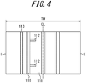
- a tread edge-side main groove 110 extending in the tread circumferential direction and adjacent to the tread ground contact edge E with the distance from the tread ground contact edge E in the tread width direction being 25% or more of the tread width TW is formed, and one of the land portions 111 adjacent to the tread ground contact edge-side land portion defined by the tread edge-side main groove 110 and the tread ground contact edge E has at least one one-end open groove 112 extending from the tread ground contact edge-side main groove 110 in the tread width direction and terminating within the adjacent land portion 111, as illustrated in FIG. 4 .
- a groove 113 in FIG. 4 is a shallow groove whose groove depth is less than that of the main groove.
- the one-end open groove 112 extending from the tread ground contact edge-side main groove 110 in the tread width direction and terminating within the land portion 111 is provided. Since the one-end open groove 112 is closed by compression stress on the vehicle-installed outside in the land portion, the deformation of the tread and the belt due to compression stress is suppressed as compared with the case where the one-end open groove 112 is not provided or the case where the one-end open groove 112 does not extend to the vehicle-installed outside.
- the one-end open groove 112 terminates within the land portion, rigidity against tensile stress increases on the vehicle-installed inside, as compared with the case where the one-end open groove 112 extends to the vehicle-installed inside. The deformation of the tread and the belt is therefore suppressed.
- the ratio L CR /TW' is preferably 0.045 or less, where L CR is a drop height which is the tire radial distance between a straight line ml through a point P on the tread surface in the tire equatorial plane CL and in parallel with the tire width direction and a straight line m2 through the ground contact edge E' and in parallel with the tire width direction in a tire widthwise cross section, and TW' is the tread width of the tire, as illustrated in FIG. 5 .
- the crown portion of the tire is flattened (planarized), thus increasing the footprint area and relieving the input of force (pressure) from the road surface.
- the deflection rate in the tire radial direction can be reduced to improve the durability and wear resistance performance of the tire.
- the “ground contact edge E'" denotes, when the tire is attached to the rim, applied with the maximum air pressure prescribed for the vehicle on which the tire is installed, put upright on a flat plate, and placed under a weight corresponding to the maximum load prescribed for the vehicle in which the tire is installed, both tire widthwise end points in the contact surface with the flat plate.
- the tread rubber may be formed of a plurality of rubber layers different in the tire width direction.
- the plurality of rubber layers may differ in loss tangent, modulus, hardness, glass transition temperature, material, or the like.
- the tire according to the present disclosure preferably has an inclined belt layer composed of a cord layer coated with rubber that extends while inclining with respect to the tire circumferential direction.
- the inclined belt layer may be made up of only one layer.
- the width of the passenger vehicle tire with the narrow-width, large-diameter size however, the footprint shape upon cornering is easily distorted if the inclined belt layer is made up of only one layer. Therefore, it is preferable to adopt an inclined belt layer extending in the direction in which the cords intersect between two or more layers.
- a belt structure in which two belt layers form an inclined belt layer is most preferable.
- the tire widthwise width of the maximum width inclined belt layer having the widest width in the tire width direction is preferably 90% to 115% of the tread width TW, and particularly preferably 100% to 105% of the tread width TW.
- metal cords and in particular steel cords are most commonly used as the belt cords of the inclined belt layer.
- organic fiber cords may also be used.
- the steel cords may include steel as a main component, and also contain various micro inclusions such as carbon, manganese, silicon, phosphorous, sulfur, copper, and chromium.
- the belt cords of the inclined belt layer may use monofilament cords or cords obtained by twisting a plurality of filaments.
- Various designs may be adopted for the twist structure, which may be different in, for example, sectional structure, twist pitch, twist direction, and/or distance of adjacent filaments.
- Cords obtained by twisting filaments of different materials may also be used, which may employ various twist structures such as single twist, layer twist, and multi twist without being limited to any particular sectional structure.
- the inclination angle of the belt cords of the inclined belt layer is preferably 10° or more with respect to the tire circumferential direction.
- the inclination angle of the belt cords of the inclined belt layer is preferably a high angle, specifically 35° or more with respect to the tire circumferential direction, and particularly in a range of 55° to 85° with respect to the tire circumferential direction.
- the inclination angle By setting the inclination angle to 35° or more, the rigidity with respect to the tire width direction is increased, and steering stability especially upon cornering is improved. In addition, the shearing deformation of the rubber between layers is reduced, and rolling resistance performance is improved.
- the tire according to the present disclosure may have a circumferential belt formed of one or more circumferential belt layers on the tire radial outer side of the inclined belt layer.
- the circumferential belt preferably has a tire circumferential rigidity per unit width of the center region C including the tire equatorial plane CL higher than the tire circumferential rigidity per unit width of the other regions.
- FIG. 6 schematically illustrates an example of the belt structure.
- circumferential belt layers 123 and 124 are laminated on the tire radial outer side of inclined belt layers 121 and 122, and in the center region C, the circumferential belt layers 123 and 124 overlap with each other in the tire radial direction.
- the tire circumferential rigidity per unit width of the center region C can be made higher than the tire circumferential rigidity per unit width of the other regions.
- the tread in a tire in which the tire circumferential rigidity of the center region including the tire equatorial plane CL has been increased, the tread preferably has a land portion that is continuous in the tire circumferential direction in a region including at least the tire equatorial plane CL of the tread surface.
- the rigidity of the tread in the region could decrease, and drastically shorten the ground contact length in the land portion defining the circumferential main groove. It is therefore preferable to dispose a land portion (rib-like land portion) that is continuous in the tire circumferential direction over a certain region including the tire equatorial plane CL, in terms of improving noise performance without decreasing cornering power.
- FIG. 7 schematically illustrates another example of the belt structure.
- one circumferential belt layer 133 is laminated on the tire radial outer side of two inclined belt layers 131 and 132.
- the inclined belt layer includes at least two inclined belt layers having different tire widthwise widths, and the inclination angle ⁇ 1 of the cords forming the inclined belt layer having the widest width with respect to the tire circumferential direction and the inclination angle ⁇ 2 of the cords forming the inclined belt layer having the narrowest width with respect to the tire circumferential direction satisfy 35° ⁇ ⁇ 1 ⁇ 85°, 10° ⁇ ⁇ 2 ⁇ 30°, and ⁇ 1 > ⁇ 2, as in the example illustrated in FIG. 7 .
- FIG. 8 schematically illustrates another example of the belt structure.
- one circumferential belt layer 143 is laminated on the tire radial outer side of two inclined belt layers 141 and 142.
- the circumferential belt layers are preferably highly rigid, and more specifically, preferably formed of a cord layer coated with rubber whose cords extend in the tire circumferential direction, which preferably satisfy 1500 ⁇ X ⁇ 750
- Y is the Young's modulus (GPa) of the cords
- n is the number of cords implanted (cords/50mm)
- m is the number of circumferential belt layers.
- the passenger vehicle tire with the narrow-width, large-diameter size is apt to be in a shape which is subjected to local deformation in the tire circumferential direction against input of force from the road surface upon cornering, so that the contact surface is likely to be in a substantially triangular shape, that is, the ground contact length in the circumferential direction greatly changes depending on the position in the tire width direction.
- the circumferential belt layers are formed to have high rigidity, thus improving the ring rigidity of the tire and suppressing deformation in the tire circumferential direction.
- deformation in the tire width direction can also be suppressed by the incompressibility of the rubber, making the ground contact shape unlikely to change.
- the improved ring rigidity promotes eccentric deformation, which simultaneously improves rolling resistance performance.
- the effect of improving rolling resistance performance is particularly extensive in the passenger vehicle pneumatic tire with the narrow-width, large-diameter size.
- the belt cords of the inclined belt layer are preferably inclined with respect to the tire circumferential direction at a high angle, specifically 35° or more.
- the use of the highly rigid circumferential belt layers increases rigidity in the tire circumferential direction, which could inadvertently reduce the ground contact length in some tires.
- belt layers inclined at a high angle may be used to reduce out-of-plane bending stiffness in the tire circumferential direction to increase the elongation of the rubber in the tire circumferential direction upon tread surface deformation, to thereby suppress a decrease in ground contact length.
- wavy-shaped cords may be used for the circumferential belt layers, in order to increase rupture strength.
- the rupture strength may similarly be increased by using high-elongation cords (for example, with an elongation at break of 4.5 to 5.5%).
- various materials may be adopted as the circumferential belt layers.
- Typical examples include rayon, nylon, polyethylene naphthalate (PEN), polyethylene terephthalate (PET), aramid, glass fiber, carbon fiber, and steel.
- PEN polyethylene naphthalate
- PET polyethylene terephthalate
- aramid polyethylene terephthalate
- glass fiber glass fiber
- carbon fiber and steel.
- organic fiber cords are particularly preferable.
- the circumferential belt layers may use, as the cords, monofilament cords, cords obtained by twisting a plurality of filaments, or hybrid cords obtained by twisting filaments of different materials.
- the number of cords implanted of the circumferential belt layers may be in a range of 20 to 60 per 50 mm, without being limited thereto.
- distributions may be provided in the tire width direction in terms of properties such as rigidity, material, the number of layers, and the density of cords implanted.
- the number of circumferential belt layers may be increased only in the tire widthwise end.
- the number of circumferential belt layers may be increased only in the center portion.
- the circumferential belt layers may be designed to be wider or narrower than the inclined belt layers.
- the circumferential belt layers may have a tire widthwise width in a range of 90% to 110% of the width of the maximum width inclined belt layer widest in tire widthwise width from among the inclined belt layers.
- the circumferential belt layers may be configured as spiral layers, which is particularly advantageous in terms of production.
- the circumferential belt layers may be omitted.
- the carcass line may employ various structures.
- the carcass maximum width position in the tire radial direction may be closer to either the bead portion side or the tread side.
- the carcass maximum width position may be in a range of 50% to 90% of the tire section height, on the tire radial outer side from the bead base portion.
- the carcass may also employ various structures.
- the number of cords in the carcass may be in a range of 20 to 60 per 50 mm, without being limited thereto.
- the carcass may have a folded end positioned on the tire radial inner side relative to the tire radial end of the bead filler.
- the carcass folded end may be positioned on the tire radial outer side relative to the tire radial outer end of the bead filler or the tire maximum width position, or may be extended, in some cases, to the tire widthwise inner side relative to the tire widthwise end of the inclined belt layer.
- the folded ends of the carcasses may be disposed at different positions in the tire radial direction.
- the carcass may be inserted between a plurality of bead core members, or wound around the bead core.
- the tire side portion is preferably reduced in thickness.
- the tire side portion may be reduced in thickness in the following manner.
- the bead filler may be configured to have a tire widthwise cross-sectional area S1 which is 1 times or more and 4 times or less the tire widthwise cross-sectional area S2 of the bead core.
- the ratio Ts/Tb may be 15% or more and 40% or less, where Ts is the gauge of the sidewall portion at the tire maximum width portion, and Tb is the bead width of the bead core at the tire radial center position.
- the ratio Ts/Tc may be 5 or more and 10 or less, where Ts is the gauge of the sidewall portion at the tire maximum width portion, and Tc is the diameter of the carcass cord.
- the gauge Ts is the total thickness of all of the members including the rubber, the reinforcement member, and the inner liner.
- Tb is the distance between the tire widthwise innermost end and outermost end of all of the small bead cores.
- the tire maximum width position may be in a range of 50% to 90% of the tire section height, on the tire radial outer side from the bead base portion.
- the tire according to the present disclosure may include a rim guard.
- the tire according to the present disclosure may include no bead filler.
- the bead core may employ various structures such as a cross-sectional circular shape and a cross-sectional polygonal shape. Further, a structure of winding the carcass around the bead core or a structure of inserting the carcass between a plurality of bead core members may be used.
- the bead portion may further include, for example, a rubber layer and a cord layer for the purpose of reinforcement and the like.
- These additional members may be provided at various positions with respect to the carcass and the bead filler.
- the inner liner thick, in terms of reducing the vehicle-interior noise of 80 Hz to 100 Hz.
- the thickness of the inner liner is preferably about 1.5 mm to 2.8 mm which is thicker than a normal inner liner (thickness of about 1.0 mm).
- the vehicle-interior noise of 80 Hz to 100 Hz tends to deteriorate especially under use of high internal pressure.
- the inner liner thick, vibration damping performance is enhanced, and the vehicle-interior noise of 80 Hz to 100 Hz is reduced. Since the inner liner has a smaller loss contributing to rolling resistance than other members such as the tread, noise performance can be improved while minimizing the degradation of the rolling resistance.
- the inner liner may be formed with a rubber layer mainly made of butyl rubber, or a film layer mainly made of resin.
- the tire inner surface may be provided with a porous member, or subjected to electrostatic flocking processing.
- the tire according to the present disclosure may include, on the tire inner surface, a sealant member for preventing air leakage upon puncture.
- the passenger vehicle pneumatic tire according to the present disclosure may be a side-reinforced run-flat tire including a reinforcing rubber having a crescent-shaped cross section in the tire side portion.
- the side portion may be simplified in structure, to realize both the run flat durability and the fuel efficiency. This is based on the finding that, in the case of a passenger vehicle pneumatic radial run-flat tire with the narrow-width, large-diameter size, the tire undergoes relatively small deformation in the side portion and the tread portion but undergoes relatively large deformation from the shoulder portion to the buttress portion during run-flat traveling. Such deformation is in contrast to that a conventional size tire undergoes relatively large deformation in the side portion.
- At least any one of the following conditions (i) to (iii) may be satisfied to simplify the tire in structure.
- FIG. 9 is a tire widthwise schematic cross-sectional view of a tire according to Embodiment 3 of the present disclosure in the case where the tire is a run flat tire.
- the circumferential main groove on the tire widthwise outermost side may be arranged closer to the tire equatorial plane CL in the tire width direction, to further improve run flat durability.
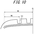
- FIG. 10 is a tire widthwise cross-sectional view of a tire according to Embodiment 4 of the present disclosure in the case where the tire is a run flat tire.
- a relational expression 0.5 ⁇ WG/WB ⁇ 0.8 is preferably satisfied, where WB is the half width in the tire width direction of the belt layer maximum in tire widthwise width from among one or more belt layers in a tire widthwise section in a reference state where the tire is attached to the rim, applied with a predetermined internal pressure, and placed under no load, and WG is the tire widthwise distance from the tire widthwise end of the belt layer maximum in tire widthwise width to the tire widthwise center position of the circumferential main groove 161 on the tire widthwise outermost side of one or more circumferential main grooves.
- the tire of Example 1 is a tire of tire size 165/60R19 as illustrated in FIGS. 1 and 2 .
- the tread rubber has a dynamic storage modulus E' of 8.6 MPa or more at a dynamic strain of 1 % and 30 °C, and is made of the rubber composition of the specifications listed in Table 1.
- Each sample tire was attached to a rim (rim size 5.5J19) and applied with an internal pressure (300 kPa).
- the sample tire was installed on a vehicle, and run on a wet road surface at 80 km/h.
Landscapes
- Engineering & Computer Science (AREA)
- Mechanical Engineering (AREA)
- Chemical & Material Sciences (AREA)
- Health & Medical Sciences (AREA)
- Chemical Kinetics & Catalysis (AREA)
- Medicinal Chemistry (AREA)
- Polymers & Plastics (AREA)
- Organic Chemistry (AREA)
- Tires In General (AREA)
- Compositions Of Macromolecular Compounds (AREA)
Applications Claiming Priority (2)
| Application Number | Priority Date | Filing Date | Title |
|---|---|---|---|
| JP2015176060A JP2017052329A (ja) | 2015-09-07 | 2015-09-07 | 乗用車用空気入りタイヤ |
| PCT/JP2016/003505 WO2017043007A1 (fr) | 2015-09-07 | 2016-07-28 | Pneumatique destiné à un véhicule de tourisme |
Publications (2)
| Publication Number | Publication Date |
|---|---|
| EP3348422A1 true EP3348422A1 (fr) | 2018-07-18 |
| EP3348422A4 EP3348422A4 (fr) | 2018-08-08 |
Family
ID=58239339
Family Applications (1)
| Application Number | Title | Priority Date | Filing Date |
|---|---|---|---|
| EP16843880.2A Withdrawn EP3348422A4 (fr) | 2015-09-07 | 2016-07-28 | Pneumatique destiné à un véhicule de tourisme |
Country Status (5)
| Country | Link |
|---|---|
| US (1) | US20180244104A1 (fr) |
| EP (1) | EP3348422A4 (fr) |
| JP (1) | JP2017052329A (fr) |
| CN (1) | CN108025594A (fr) |
| WO (1) | WO2017043007A1 (fr) |
Cited By (1)
| Publication number | Priority date | Publication date | Assignee | Title |
|---|---|---|---|---|
| WO2021250331A1 (fr) * | 2020-06-11 | 2021-12-16 | Compagnie Generale Des Etablissements Michelin | Pneumatique émettant un bruit réduit |
Families Citing this family (13)
| Publication number | Priority date | Publication date | Assignee | Title |
|---|---|---|---|---|
| JP6558297B2 (ja) * | 2016-04-26 | 2019-08-14 | 横浜ゴム株式会社 | 空気入りタイヤ |
| EP3496957B1 (fr) * | 2016-08-08 | 2021-01-06 | Bridgestone Bandag, LLC | Pneumatiques comprenant un composé de base à faible déchirure pour bande de roulement de pneu |
| JP6878813B2 (ja) * | 2016-10-03 | 2021-06-02 | 住友ゴム工業株式会社 | ベーストレッド用ゴム組成物 |
| JP7360314B2 (ja) | 2019-12-13 | 2023-10-12 | 株式会社ブリヂストン | ベーストレッド用ゴム組成物及びタイヤ |
| EP4074519B1 (fr) * | 2019-12-13 | 2023-12-13 | Bridgestone Corporation | Composition de caoutchouc de bande de roulement de base et pneumatique |
| JP6863503B1 (ja) * | 2020-04-24 | 2021-04-21 | 住友ゴム工業株式会社 | タイヤ |
| JP6800435B1 (ja) * | 2020-07-28 | 2020-12-16 | 住友ゴム工業株式会社 | 空気入りタイヤ |
| JP6835284B1 (ja) * | 2020-07-28 | 2021-02-24 | 住友ゴム工業株式会社 | 空気入りタイヤ |
| JPWO2022025008A1 (fr) | 2020-07-28 | 2022-02-03 | ||
| JP6880541B1 (ja) | 2020-08-28 | 2021-06-02 | 住友ゴム工業株式会社 | 空気入りタイヤ |
| JPWO2022050153A1 (fr) | 2020-09-04 | 2022-03-10 | ||
| CN116635246A (zh) * | 2020-12-28 | 2023-08-22 | 住友橡胶工业株式会社 | 充气轮胎 |
| JP2024014499A (ja) * | 2022-07-22 | 2024-02-01 | 住友ゴム工業株式会社 | タイヤ |
Family Cites Families (15)
| Publication number | Priority date | Publication date | Assignee | Title |
|---|---|---|---|---|
| US6797757B2 (en) * | 2001-06-29 | 2004-09-28 | The Goodyear Tire & Rubber Company | Article, including tires, having component or rubber composition which contains particles of pre-vulcanized rubber and blend of tetrathiodipropionic and trithiodipropionic acids |
| DE602004026601D1 (de) * | 2003-09-05 | 2010-05-27 | Bridgestone Corp | Luftreifen |
| EP2261282A3 (fr) * | 2003-11-28 | 2012-03-21 | Sumitomo Rubber Industries, Ltd. | Composition de caoutchouc pour pneu et pneu utilisant celle-ci |
| JP4124758B2 (ja) * | 2004-08-17 | 2008-07-23 | 住友ゴム工業株式会社 | ゴム組成物およびそれを用いたタイヤ |
| JP4581732B2 (ja) * | 2005-02-16 | 2010-11-17 | 横浜ゴム株式会社 | 空気入りタイヤ |
| JP2008260517A (ja) * | 2007-03-16 | 2008-10-30 | Bridgestone Corp | 空気入りタイヤ |
| US20090005481A1 (en) * | 2007-06-27 | 2009-01-01 | Sumitomo Rubber Industries, Ltd. | Rubber composition for tire, tire member and tire |
| CN103097149B (zh) * | 2010-08-25 | 2015-11-25 | 株式会社普利司通 | 充气轮胎 |
| WO2012073837A1 (fr) * | 2010-12-03 | 2012-06-07 | 横浜ゴム株式会社 | Composition de caoutchouc pour bande de roulement |
| US10207541B2 (en) * | 2011-08-26 | 2019-02-19 | Bridgestone Corporation | Pneumatic radial tire for a passenger vehicle and method of using the same |
| US20140296375A1 (en) * | 2011-10-24 | 2014-10-02 | Bridgestone Americas Tire Operations, Llc | Silica-Filled Rubber Composition And Method For Making The Same |
| WO2013065319A1 (fr) * | 2011-11-02 | 2013-05-10 | 株式会社ブリヂストン | Pneu radial d'automobile, et procédé d'utilisation correspondant |
| JP6392748B2 (ja) * | 2013-04-30 | 2018-09-19 | 株式会社ブリヂストン | 乗用車用空気入りラジアルタイヤ |
| JP6317140B2 (ja) * | 2014-03-05 | 2018-04-25 | 株式会社ブリヂストン | 空気入りタイヤ |
| JP5810204B1 (ja) * | 2014-10-08 | 2015-11-11 | 株式会社ブリヂストン | 乗用車用空気入りラジアルタイヤ |
-
2015
- 2015-09-07 JP JP2015176060A patent/JP2017052329A/ja active Pending
-
2016
- 2016-07-28 EP EP16843880.2A patent/EP3348422A4/fr not_active Withdrawn
- 2016-07-28 CN CN201680051935.XA patent/CN108025594A/zh active Pending
- 2016-07-28 US US15/756,192 patent/US20180244104A1/en not_active Abandoned
- 2016-07-28 WO PCT/JP2016/003505 patent/WO2017043007A1/fr active Application Filing
Cited By (1)
| Publication number | Priority date | Publication date | Assignee | Title |
|---|---|---|---|---|
| WO2021250331A1 (fr) * | 2020-06-11 | 2021-12-16 | Compagnie Generale Des Etablissements Michelin | Pneumatique émettant un bruit réduit |
Also Published As
| Publication number | Publication date |
|---|---|
| JP2017052329A (ja) | 2017-03-16 |
| EP3348422A4 (fr) | 2018-08-08 |
| WO2017043007A1 (fr) | 2017-03-16 |
| CN108025594A (zh) | 2018-05-11 |
| US20180244104A1 (en) | 2018-08-30 |
Similar Documents
| Publication | Publication Date | Title |
|---|---|---|
| EP3348422A1 (fr) | Pneumatique destiné à un véhicule de tourisme | |
| JP6758088B2 (ja) | 空気入りタイヤ | |
| EP3348423A1 (fr) | Pneumatique | |
| EP3279011B1 (fr) | Pneumatique | |
| EP3205515B1 (fr) | Pneu à carcasse radiale pneumatique pour véhicule de tourisme | |
| EP3279012B1 (fr) | Pneumatique | |
| JP6605460B2 (ja) | 乗用車用空気入りラジアルタイヤ | |
| EP3130479B1 (fr) | Bandage pneumatique radial destiné à être utilisé sur un véhicule de tourisme | |
| JP6527750B2 (ja) | 空気入りタイヤ | |
| US10639936B2 (en) | Pneumatic tire | |
| JP2016074408A (ja) | 乗用車用空気入りラジアルタイヤ | |
| JP2022029764A (ja) | タイヤ | |
| JP7159999B2 (ja) | 空気入りタイヤ | |
| JP2022029368A (ja) | タイヤ | |
| JP6393658B2 (ja) | 空気入りタイヤ | |
| JP2023025806A (ja) | タイヤ |
Legal Events
| Date | Code | Title | Description |
|---|---|---|---|
| PUAI | Public reference made under article 153(3) epc to a published international application that has entered the european phase |
Free format text: ORIGINAL CODE: 0009012 |
|
| 17P | Request for examination filed |
Effective date: 20180306 |
|
| AK | Designated contracting states |
Kind code of ref document: A1 Designated state(s): AL AT BE BG CH CY CZ DE DK EE ES FI FR GB GR HR HU IE IS IT LI LT LU LV MC MK MT NL NO PL PT RO RS SE SI SK SM TR |
|
| AX | Request for extension of the european patent |
Extension state: BA ME |
|
| A4 | Supplementary search report drawn up and despatched |
Effective date: 20180710 |
|
| RIC1 | Information provided on ipc code assigned before grant |
Ipc: B60C 11/03 20060101ALI20180702BHEP Ipc: B60C 1/00 20060101AFI20180702BHEP Ipc: B60C 11/12 20060101ALI20180702BHEP Ipc: B60C 11/00 20060101ALI20180702BHEP Ipc: B60C 3/04 20060101ALI20180702BHEP |
|
| DAV | Request for validation of the european patent (deleted) | ||
| DAX | Request for extension of the european patent (deleted) | ||
| STAA | Information on the status of an ep patent application or granted ep patent |
Free format text: STATUS: THE APPLICATION IS DEEMED TO BE WITHDRAWN |
|
| 18D | Application deemed to be withdrawn |
Effective date: 20190207 |