EP3345809A2 - Mittelrunge für sattelauflieger - Google Patents
Mittelrunge für sattelauflieger Download PDFInfo
- Publication number
- EP3345809A2 EP3345809A2 EP17460011.4A EP17460011A EP3345809A2 EP 3345809 A2 EP3345809 A2 EP 3345809A2 EP 17460011 A EP17460011 A EP 17460011A EP 3345809 A2 EP3345809 A2 EP 3345809A2
- Authority
- EP
- European Patent Office
- Prior art keywords
- arm
- hook module
- semi
- stanchion
- post
- Prior art date
- Legal status (The legal status is an assumption and is not a legal conclusion. Google has not performed a legal analysis and makes no representation as to the accuracy of the status listed.)
- Granted
Links
Images


Classifications
-
- B—PERFORMING OPERATIONS; TRANSPORTING
- B62—LAND VEHICLES FOR TRAVELLING OTHERWISE THAN ON RAILS
- B62D—MOTOR VEHICLES; TRAILERS
- B62D33/00—Superstructures for load-carrying vehicles
- B62D33/02—Platforms; Open load compartments
- B62D33/0207—Connections of movable or detachable racks or stanchions to platforms
-
- B—PERFORMING OPERATIONS; TRANSPORTING
- B62—LAND VEHICLES FOR TRAVELLING OTHERWISE THAN ON RAILS
- B62D—MOTOR VEHICLES; TRAILERS
- B62D33/00—Superstructures for load-carrying vehicles
- B62D33/04—Enclosed load compartments ; Frameworks for movable panels, tarpaulins or side curtains
Definitions
- the object of the invention is a middle rungs for semi-trailers, which is quickly removable and especially intended for various types of semi-trailers and trailers, especially for agricultural, universal or even sub-container semi-trailers.
- the pivotal support which is especially used on vehicles and semi-trailers with tarpaulins, has a housing that consists of a U-profile and a flat iron, which are firmly bound and form a closed rectangular profile. Inside the housing, a locking device is arranged, the locking lever is rotatably and pivotally inserted in longitudinal holes. In the levers there are articulated tie rods, both of which are connected to two separate wedges by means of a slider and a bolt, to which pin a spring is mounted between the slider and the bolt-bearing support.
- the semitrailer mullion illustrated therein which is releasably engaged with a contoured end in the pocket rigidly attached to the chassis wall, consists of a latch lock having a hinged lever coupled to the opening by an eccentric pivot and a sliding rod with a sliding coaxial locking wedge of the resistance strap located in the pocket.
- the lock lever also has an extension arm extended along its axis of rotation, which is articulated by a hinge and slide with sliders disposed along the post Blocking fork is connected, in the top of the bolt support, which clips together with a cross piece, the opposite walls of the semitrailer.
- the invention describes the assembly and disassembly of a post for semi-trailer in an unconventional way.
- the rotatable support which provides additional support for the upright, is attached to the fixing element [tensioning element] and in the folded and neutral position parallel to the lower edge of the semitrailer and does not project beyond the vehicle outer surface. It is rotatably mounted in the rotating mechanism, which is placed in the fastener. Above the fastener is a lock securing and locking the post in the neutral and retracted position. The lock is firmly attached to the side edge of the semi-trailer.
- a fastener is installed at the other end of the rotatable support.
- the support of the post requires the removal of the post from the lock, unlocking the post and supporting the post thereon.
- the spring mechanism allows the rotation of the movable support by 90 ° and their blocking in extreme points ie. in the starting and unfolding position.
- the subject of the invention is a ball coupling for a resident with a operated by the handle designed in the form of a blank element ball socket, connected to - a vehicle-mounted ball, which is manually operated with safety part, with the aid of which in a closed position of the ball socket Inclination of the handle is locked - and with one, in the operating position vertically in the direction of the inclination of the handle placed and thereby extending, bolt-like closing device, characterized in that the closing device is free of gaps or almost free of columns adjacent to the pan, spherical end face or adjacent to the inner wall of the handle.
- the aim of the invention is to provide a middle rungs for semi-trailer, which can be assembled and disassembled quickly - significantly faster, as is the case with previous designs, so in the end, the assembly and disassembly of such a center postion also thanks to the simple and fluent acting lever system lighter.
- the essence of the Mittelrunge for semi-trailer is that the middle stanchion is placed in the executed on the side wall bag, wherein in the lower part of the Mittelrunge a security lock is attached, which consists of a lower lever, an arm and a lockable on the pin safety hook module , The arm is hinged to the hook module - so that in this way a rotational movement of the hook module is possible.
- the arm On the other side to the modular hook attachment - the arm is rotatably attached to the lower lever.
- the lower lever is fixed to the central stanchion by means of a bolt which determines the axis of rotation of the lever, thereby displacing the axle relative to the attachment of the arm to the lever.
- the axis of rotation of the oscillating arm is located in the opening, at the point of connection of the arm and hook module.
- the safety lock is formed as a whole by: the hook module, the arm and the lower lever, so the eccentric mechanism.
- the length of the arm is adjustable.
- the hook module forms a correspondingly shaped, rounded flat bar, which has two rounded branches, and in the center of which there are an opening and a throughbore.
- the through hole at the point where the hook module is connected to the central rungs also realized by means of a vertically placed pin [pin].
- one of the branches of the flat bar so the hook module forms a holder.
- the axis of rotation of the hook module is located exactly in the middle of the throughbore.
- a lifter is attached to the middle stanchion, in the upper part, on which a rod is articulated.
- the connection of the jack with the center post and the pole is disconnected, and the pole has a latch which blocks the upper part of the center post and slides it over the roof truss of the semitrailer.
- the upper part of the middle stanchion is unsecured and unlocked.
- the rod is adjustable in length.
- this solution enables efficient assembly and disassembly of the center post for a resident, which improves the sustainability of the trailer wall during transport. This makes loading and unloading cargo even more efficient by expanding the opening diameter in the opened trailer or trailer wall.
- the advantage of the solution according to the invention is the particularly simple securing mechanism which, despite the fact that it allows the unlocking of the quickly removable middle stanchions for semitrailers, by a user, but prevents the opening of the center mandrels for semi-trailers during transport.
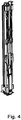
- Fig. 1 Axonometric view of the open semi-trailer with built-in center post for semi-trailer
- Fig.2 Perspective view of the closed semitrailer with built-in middle stanchions for semi-trailers
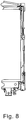
- Fig. 3 the center stanchion for semi-trailers, placed in the side wall bag and attached to roof trusses of the semitrailer
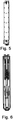
- Fig. 4 Center post for semi-trailer in axonometric view from the outside
- Fig. 1 Axonometric view of the open semi-trailer with built-in center post for semi-trailer
- Fig.2 Perspective view of the closed semitrailer with built-in middle stanchions for semi-trailers
- Fig. 3 the center stanchion for semi-trailers, placed in the side wall bag and attached to roof trusses of the semitrailer
- Fig. 4 Center post for semi-trailer in axonometric view from the outside
- Fig. 1
- the lower part of the middle post 1 placed in the pocket 2 has a security lock consisting of the lower lever 4, adjustable arm 5, hook module 6 for security purposes and a pin 7.
- the hook module 6 for security purposes (in the Fig. 8 and Fig. 9 shown) - is locked to the pin 7, and thus protects the middle stanchion 1 from falling out of the pocket 2.
- articulated arm 5 is mounted so that rotational movements of the hook module 6 are possible.
- the arm 5 is preferably adjustable so that its length can be adapted to different types and sizes of semi-trailers.
- the arm 5, on the other side to the modular hook attachment 6, is rotatably attached to the lower lever 4.
- the lower lever 4 In the secured position of the middle post 1, the lower lever 4 is directed downwards, parallel to the middle post 1.
- the lower lever 4 is fixed to the central post 1 by means of bolts 8, which determines the axis of rotation of the lever 4.
- the rotation axis of the lower lever 4 is shifted relative to the attachment of the arm 5 and is at the location of the bolt 8.
- actuated arm 5 also performs pivotal movement from - in this case in a much smaller circular section whose center is located in the opening 9, ie. at the connection of the arm 5 with the hook module 6. This point forms an axis of rotation for the arm 5.
- the opening 9, ie connection point of the arm 5 with the hook module 6, moves according to commissioning of the mechanism.
- the hook module 6 is a correspondingly shaped, rounded flat bar, which has two rounded branches, and at its center are: opening 9 and through-hole 10. The function of the opening 9 has been described above.
- the throughbore 10 forms a connection point for the hook module 6 with the center post 1, also realized by means of a vertically placed bolt.
- the opening 9 allows articulated connection of the arm 5 with the hook module. 6
- Described embodiment of the hook module 6 allows rotational movement more precisely to perform pivotal movement.
- the axis of rotation of the hook module 6 is located exactly in the middle of the through hole 10.
- the hook module 6, the arm 6 and the lower lever 4 - which form the eccentric mechanism - thus form a security lock.
- the holder 9 slides directly on the - parallel to the side wall 3 of the semitrailer and perpendicular to the flat bar, which forms the hook module 6, attached - protection pin 7 and hooks him, or emerges from it, whereby the middle stanchion 1 is locked or unlocked in the pocket 2 of the side wall 3 of the semitrailer.
- the middle rungs 1 are preferably two such side by side attached security locks.
- the eccentric mechanism with the hook module 6 is designed so that it locks when the lock is unlocked or unlocked Semi-trailer to jump over the dead center comes.
- yet another safety mechanism for the middle postion 1 was provided according to the invention, which is located in the upper part, ie at the point of connection of the middle post 1 with the roof truss of the semitrailer ( Figure 10 ).
- the lifter 12 is mounted, to which the rod 13 has also been articulated, which is adjustable in length - as is the case with the arm 5 - so that they can be of different types from trailers and semi-trailers.
- the connection of the lifter 12 to the center post 1 and to the post 13 is separate, non-intersecting, eccentric.
- the rod 13 has a latch 14 which blocks the upper part of the middle post 1 and which is pushed over the roof truss.
- the lifter 12 forms a right angle between the middle stanchions 1, then the upper part of the middle stanchion 1 is unsecured and unlocked.
- To lock the mechanism one should pull the lifter 12 downwards, as it performs a movement in the circular cutout, causing such a movement of the rod 13, that it pushes the latch 14 upwards and thus protects the middle stanchions from being unlocked , In this situation, see Fig. 8 -
- the lifter 12 is parallel to the middle stanchions 1.
- the middle post 1 is only well anchored in the pocket 3 of the side wall 3 of the semitrailer when both: the lower lever 4 and the upper lift 12 are parallel to the middle post 1. Only such location allows appropriate use of the middle rung 1 and its secure attachment to the semi-trailer, especially for agricultural purposes.
Landscapes
- Engineering & Computer Science (AREA)
- Chemical & Material Sciences (AREA)
- Combustion & Propulsion (AREA)
- Transportation (AREA)
- Mechanical Engineering (AREA)
- Vehicle Cleaning, Maintenance, Repair, Refitting, And Outriggers (AREA)
- Lock And Its Accessories (AREA)
- Emergency Lowering Means (AREA)
Abstract
Description
- Der Gegenstand der Erfindung ist eine Mittelrunge für Sattelauflieger, die schnell abnehmbar und vor allem für verschiedenartige Sattelauflieger und Anhänger bestimmt ist, insbesondere für landwirtschaftliche, universelle oder sogar Unter-Container-Sattelauflieger.
- Es gibt viele unterschiedliche Konstruktionslösungen von Mittelrungen für Sattelauflieger. Aus der polnischen Beschreibung der Erfindung Nr. P-329446 (Veröffentlichungsdatum im ABI. 1999-11-22) ist eine Lösung bekannt "Schwenkstütze für Bordwände an LKWs". Die besonders an Fahrzeugen und Sattelaufliegern mit Planen verwendete Schwenkstütze besitzt ein Gehäuse, das aus einem U-Profil und einem Flacheisen besteht, die fest gebunden sind und ein geschlossenes Rechteckprofil bilden. Im Inneren des Gehäuses ist eine Verriegelungseinrichtung angeordnet, derer Verriegelungshebel dreh- und schwenkbar in Längslöchern eingesetzt ist. In der Hebel gibt es gelenkartig eingesetzte Zugstangen, von denen beide mit zwei getrennten Keilen mit Hilfe von einem Schieber und einem Bolzen verbunden sind, wobei an dem Bolzen eine Feder zwischen dem Schieber und der zum Bolzen gehörenden Stütze angebracht ist.
- Aus der polnischen Beschreibung des Gebrauchsmusters Nr. W-120762 (Veröffentlichungsdatum im ABI. 2013-08-19) ist weiter eine Lösung "Mittelpfosten für Sattelauflieger" bekannt. Der dort dargestellte Mittelpfosten für Sattelauflieger, der lösbar mit konturiertem Ende in der fest an Fahrgestell-Wand angebrachten Tasche eingesetzt ist, besteht aus einem Verriegelungsschloss, das einen aufklappbaren Hebel besitzt, der durch ein Exzentergelenk und eine Zugstange mit gleitendem, koaxialem Verriegelungskeil mit der Öffnung des in der Tasche lokalisierten Widerstandsbügels verbunden ist. Der Schließhebel besitzt außerdem einen über dessen Drehachse verlängerten, zusätzlichen Arm, der durch ein Gelenk und einen Schieber mit gleitendem, entlang den Pfosten angeordnetem Blockierungs-Gabelkeil verbunden ist, in der Spitze der Bolzenstütze, die mit einem Querstück die gegenüberliegenden Wände des Sattelanliegers zusammenklammert.
- Aus der weiteren polnischen Beschreibung der Erfindung Nr. P-410869 (Veröffentlichungsdatum im ABI. 2016-07-04) ist eine Lösung "Stützpfosten für einen Anlieger" bekannt. Die Erfindung beschreibt die Montage und Demontage von einem Pfosten für Sattelauflieger auf unkonventionelle Weise. Die drehbare Stütze, die eine zusätzliche Abstützung für den Pfosten bildet, ist am Befestigungselement [Spannelement] angebracht und in der eingeklappten und neutralen Position parallel zur Unterkante des Sattelaufliegers und ragt über die Fahrzeugaußenfläche nicht hervor. Dabei ist sie drehbar im Drehmechanismus montiert, das im Befestigungselement platziert ist. Über dem Befestigungselement befindet sich ein Schloss, das den Pfosten in der neutralen und eingeklappten Position sichert und verriegelt. Das Schloss ist fest am Seitenrand des Sattelaufliegers angebracht. An dem anderen Ende der drehbaren Stütze ist ein Befestigungselement eingebaut. Die Abstützung des Pfostens erfordert die Herausziehung des Pfostens aus dem Schloss, Entriegelung der Stütze und Aufstützung des Pfostens darauf. Um dieses Ziel zu erreichen, muss man das Blockierelement entsperren und lockern, anschließend die drehbare Stütze um die Achse, die den Drehmechanismus bildet, drehen und den Pfosten an dem - zum Befestigungselement entgegengesetzten - Ende abstützen. Dabei ermöglicht der Federmechanismus die Drehung der beweglichen Stütze um 90° und deren Blockierung in äußersten Punkten dh. in der Ausgangs- und Ausklappposition.
- Aus der weiteren polnischen Beschreibung der Erfindung Nr. P-338535 (Veröffentlichungsdatum im ABI. 2009-04-30) ist eine Lösung "Kugelkupplung für einen Anlieger" bekannt. Der Gegenstand der Erfindung ist eine Kugelkupplung für einen Anlieger mit einer durch den in Form von einem leeren Element gestalteten Griff betätigten Kugelpfanne, verbunden mit - einer am Fahrzeug angebrachten Kugel, die mit Sicherheitsteil handbetätigt wird, mit dessen Hilfe in einer geschlossenen Position der Kugelpfanne die Neigung des Griffes gesperrt wird - und mit einer, in der Betriebsstellung senkrecht in Richtung der Neigung des Griffes platzierten und dadurch verlaufenden, bolzenartigen Schließvorrichtung, dadurch gekennzeichnet, dass die Schließvorrichtung spaltenfrei oder fast spaltenfrei an die zur Pfanne gerichtete, kugelförmige Stirnfläche oder an gegenüberliegende Innenwand des Griffes angrenzt.
- Das Ziel der Erfindung ist so eine Mittelrunge für Sattelauflieger zu schaffen, den man schnell montieren und demontieren kann - bedeutend schneller, wie das bei bisherigen Konstruktionen der Fall ist, so ist im Endergebnis die Montage und Demontage einer solchen Mittelrunge auch dank dem einfach und fließend wirkenden Hebelsystem leichter.
- Das Wesentliche der Mittelrunge für Sattelauflieger ist, dass die Mittelrunge in der an der Bordwand ausgeführten Tasche platziert ist, wobei im unteren Teil der Mittelrunge ein Sicherheitsschloss angebracht ist, das aus einem unteren Hebel, einem Arm und einem an dem Stift verriegelbaren Sicherungshaken-Modul besteht. Der Arm ist gelenkartig an dem Haken-Modul befestigt - so dass auf diese Weise eine Drehbewegung des Haken-Moduls möglich ist. Auf der anderen Seite zur modularen Hakenbefestigung - ist der Arm drehbar an dem unteren Hebel angebracht. Der untere Hebel ist an der Mittelrunge mittels einem Bolzen befestigt, der die Drehachse des Hebels bestimmt, so ist dadurch die Achse gegenüber der Befestigung des Armes zum Hebel verschoben. Nach Inbetriebsetzung und Hochheben des unteren Hebels führt dieser eine Schwingbewegung nach dem Teilkreis aus, dessen Mitte durch die Drehachse des unteren Hebels, also den Bolzen bestimmt ist. Die Drehachse des in Schwingbewegung versetzten Armes befindet sich in der Öffnung, an der Stelle der Verbindung des Armes und Haken-Moduls. Das Sicherungsschloss wird insgesamt gebildet von: dem Haken-Modul, dem Arm und dem unteren Hebel, also dem Exzentermechanismus.
- Vorzugsweise ist die Länge des Armes verstellbar.
- Vorzugsweise bildet das Haken-Modul eine entsprechend geformte, abgerundete Flachstange, die zwei abgerundete Abzweigungen aufweist, und in deren Mitte sich eine Öffnung und eine Durchbohrung befinden.
- Vorzugsweise befindet sich die Durchbohrung an der Stelle, wo das Haken-Modul mit der Mittelrunge verbunden ist, auch mittels einem senkrecht platziertem Bolzen [Stift] realisiert.
- Vorzugsweise bildet eine der Abzweigungen der Flachstange, also des Haken-Moduls einen Halter.
- Vorzugsweise befindet sich die Drehachse des Haken-Moduls genau in der Mitte der Durchbohrung.
- Vorzugsweise gibt es an der Mittelrunge mehr als ein Sicherheitsschloss, Vorzugsweise gibt es zwei Sicherheitsschlösser.
- Abgesehen von den Obigen, ist an der Mittelrunge, in dessen oberen Teil, ein Heber befestigt, an dem gelenkartig eine Stange angebracht ist. Dabei ist die Verbindung des Hebers mit der Mittelrunge und mit der Stange getrennt, und die Stange verfügt über einen Riegel, der das obere Teil der Mittelrunge blockiert und über den Dachbinder des Sattelanliegers geschoben wird. In der Lage, wo sich der Heber senkrecht zur Mittelrunge befindet - ist das obere Teil des Mittelrunge ungesichert und entriegelt.
- Vorzugsweise ist die Stange in der Länge verstellbar.
- Erfindungsgemäß ermöglicht diese Lösung effiziente Montage und Demontage des Mittelrunge für einen Anlieger, der die Tragfähigkeit der Aufliegerwand während des Transports verbessert. Dadurch ist das Be- und Entladen von Fracht noch effizienter, weil der Öffnungsdurchmesser in der aufgemachten Auflieger- oder Anhängerwand erweitert wird.
- Der Vorteil der Lösung ist laut Erfindung der besonders einfache Sicherungsmechanismus, das trotz der Tatsache, dass er die Entriegelung des schnell abnehmbaren Mittelrungen für Sattelauflieger ermöglicht, von einem Nutzer, verhindert aber das Aufsperren der Mitteldorne für Sattelauflieger beim Transport.
- Der Gegenstand der Erfindung wurde näher am Ausführungsbeispiel in den Zeichnungen erläutert, in denen dargestellt wurden:
Fig. 1 - axonometrische Ansicht des geöffneten Sattelaufliegers mit eingebauter Mittelrunge für Sattelanlieger,Fig.2 - perspektivische Ansicht des geschlossenen Sattelananliegers mit eingebauter Mittelrungen für Sattelanlieger,Fig. 3 - der in der Bordwand-Tasche platzierte und an Dachbinder des Sattelaufliegers angebrachte Mittelrunge für Sattelauflieger,Fig. 4 - Mittelrunge für Sattelauflieger in axonometrischer Ansicht von außen,Fig. 5 - Mittelrunge für Sattelauflieger in axonometrischer Ansicht von innen,Fig.6 - Mittelrunge für Sattelauflieger in Vorderansicht,Fig. 7 - Durchschnitt durch den Sattelauflieger mit eingebautem und entriegeltem Mittelrunge für Sattelanhänger,Fig. 8 - Durchschnitt durch den Sattelauflieger mit eingebauter und verriegelter Mittelrunge für Sattelauflieger,Fig.9 - Arretierungsmechanismus der Mittelrunge in geöffneter Position von nah,Fig. 10 dagegen - Mechanismus des oberen Teils von der Mittelrunge. - Was mit Zeichnungen veranschaulicht wurde, befindet sich die Mittelrunge 1 in der früher vorbereiteten Tasche 2, die in dem entsprechenden Bordtyp 3 des Sattelaufliegers ausgeführt wird. Das untere Teil des in der Tasche 2 platzierten Mittelrunge 1 besitzt ein Sicherheitsschloss, das aus unterem Hebel 4, verstellbarem Arm 5, Haken-Modul 6 für Sicherheitszwecken und einem Stift 7 besteht. Das Haken-Modul 6 für Sicherheitszwecken (in den
Fig. 8 undFig. 9 dargestellt) - ist am Stift 7 verriegelt, und schützt auf diese Weise den Mittelrunge 1 vor dem Herausfallen aus der Tasche 2. Am Haken-Modul 6 ist gelenkartig Arm 5 so angebracht, dass Drehbewegungen des Haken-Moduls 6 möglich sind. Der Arm 5 ist vorzugsweise so verstellbar, dass man seine Länge an verschiedenen Typen und Größen von Sattelaufliegern anpassen kann. Der Arm 5, auf der anderen Seite zur modularen Hakenbefestigung 6, ist drehbar an den unteren Hebel 4 angebracht. - In der abgesicherten Lage der Mittelrunge 1 ist der untere Hebel 4 nach unten gerichtet, parallel zur Mittelrunge 1. Der untere Hebel 4 ist an der Mittelrunge 1 mittels Bolzen 8 befestigt, der die Drehachse des Hebels 4 bestimmt. Auf diese Weise ist die Drehachse des unteren Hebels 4 gegenüber der Befestigung des Armes 5 verschoben und befindet sich an der Stelle des Bolzens 8. So eine Konstruktion verursacht, dass nach Inbetriebnahme des Mechanismus und beim Hochheben des unteren Hebels 4 führt er Schwenkbewegung im Kreisausschnitt aus, dessen Mittelpunkt durch die Drehachse des unteren Hebels 4, also den Bolzen 8 bestimmt wird. Auf diese Weise betätigter Arm 5 führt auch Schwenkbewegung aus - in diesem Fall in wesentlich kleinerem Kreisausschnitt, dessen Mittelpunkt sich in der Öffnung 9 befindet, dh. an der Verbindung des Armes 5 mit dem Haken-Modul 6. Diese Stelle bildet eine Drehachse für den Arm 5. Die Öffnung 9, also Verbindungstelle des Armes 5 mit dem Haken-Modul 6, bewegt sich entsprechend bei Inbetriebnahme des Mechanismus.
- Die Betätigung des unteren Hebels 4 samt dem Arm 5 verursacht die Bewegung des speziell konstruierten Haken-Moduls 6.
- Das Haken-Modul 6 ist eine entsprechend geformte, abgerundete Flachstange, die zwei abgerundete Abzweigungen aufweist, und in deren Mitte befinden sich: Öffnung 9 und Durchbohrung 10. Die Funktion der Öffnung 9 wurde oben beschrieben.
- Die Durchbohrung 10 bildet dagegen eine Verbindungsstelle für das Haken-Modul 6 mit dem Mittelrunge 1, auch mittels einem senkrecht platziertem Bolzen realisiert.
- Eine der Abzweigungen der Flachstange, also des Haken-Moduls 6 bildet den Halter 11.
- Die Öffnung 9 ermöglicht gelenkartige Verbindung des Armes 5 mit dem Haken-Modul 6.
- Beschriebene Ausgestaltung des Haken-Moduls 6 erlaubt Drehbewegung genauer gesagt Schwenkbewegung auszuführen.
- Die Drehachse des Haken-Moduls 6 befindet sich genau in der Mitte der Durchbohrung 10. Das Haken-Modul 6, der Arm 6 und der untere Hebel 4 - die das Exzentermechanismus formen - bilden also ein Sicherheitsschloss.
- Während der Bewegung [Wagenverkehrs] des Haken-Moduls 6, schiebt sich der Halter 9 direkt auf den - parallel zur Bordwand 3 des Sattelaufliegers und senkrecht zur Flachstange, die das Haken-Modul 6 bildet, angebrachten - Schutzstift 7 und hakt ihn an, oder tritt daraus hervor, wodurch die Mittelrunge 1 in der Tasche 2 der Bordwand 3 des Sattelaufliegers verriegelt oder entriegelt wird. An dem Mittelrunge 1 befinden sich vorzugsweise zwei solche nebeneinander angebrachte Sicherheitsschlösser. Der Exzentermechanismus mit dem Haken-Modul 6 ist so konstruiert, dass es bei Verriegelung oder Entriegelung des Schlosses vom Sattelauflieger zum Sprung über den Totpunkt kommt. Zu diesem Sprung kommt es im Moment, wenn alle drei Verbindungen dh.: die Verbindung des unteren Hebels 4 mit dem Arm 5, die Verbindung des Armes 5 mit dem Haken-Modul 6 mittels Öffnung 9 und die Verbindung des unteren Hebels 4 mit der Mittelrunge 1 - auf einer Linie liegen (grundsätzlich parallelen zu dem senkrechten Mittelrunge 1). Dieser Sprung schützt das Schloss des Sattelaufliegers vor Selbstentriegelung beim Transport.
- In dieser Lösung wurde erfindungsgemäß noch ein anderer Sicherheitsmechanismus für die Mittelrunge 1 vorgesehen, der sich in dessen oberen Teil befindet, also an der Stelle der Verbindung der Mittelrunge 1 mit dem Dachbinder des Sattelaufliegers (
Fig.10 ). - An der Mittelrunge 1, in dessen oberen Teil, wird der Heber 12 montiert, zu dem man auch gelenkartig die Stange 13 angebracht hat, die in der Länge - ebenso wie bei dem Arm 5 der Fall ist - verstellbar ist, damit man sie verschiedenen Typen von Anhängern und Sattelanliegern anpassen konnte. So ist die Verbindung des Hebers 12 mit der Mittelrunge 1 und mit der Stange 13 getrennt, nicht überschneidend, exzentrisch. Die Stange 13 weist einen Riegel 14 auf, der den oberen Teil der Mittelrunge 1 blockiert und der über den Dachbinder geschoben wird.
- Bildet der Heber 12 einen rechten Winkel zwischen den Mittelrungen 1, dann ist der obere Teil der Mittelrunge 1 ungesichert und entriegelt. Um den Mechanismus zu verriegeln, soll man den Heber 12 nach unten ziehen, da führt er eine Bewegung im Kreisausschnitt aus, was solch eine Bewegung der Stange 13 bewirkt, dass sie den Riegel 14 nach oben schiebt und auf diese Weise den Mittelrungen vor Entriegelung schützt. In dieser Lage, siehe
Fig. 8 - liegt der Heber 12 parallel zur Mittelrungen 1. Man muss umgekehrt handeln, wenn man die Mittelrunge 1 entriegeln will, der gewöhnlich mit zwei solchen Mechanismen ausgestattet ist. (ebenso wie bei zwei Sicherheitsschlösser in dem unteren Teil). - Das bedeutet, dass alle vier Mechanismen verriegelt oder entriegelt werden müssen, damit die Wirkung erfindungsgemäß erfolgreich ist. So, bei der Demontage die Mittelrunge 1 muss man sich vergewissern, dass beide: der untere Hebel 4 und der obere Heber 12 mit der Mittelrunge 1 einen rechten Winkel bilden. Solche Anordnung von Elementen ermöglicht leichte und effiziente Demontage der Mittelrunge 1 und Erweiterung der Öffnung des Sattelaufliegers, was besonders bei landwirtschaftlichen Anliegern von Vorteil ist.
- Und umgekehrt, die Mittelrunge 1 wird nur dann in der Tasche 3 der Bordwand 3 des Sattelanliegers gut verankert, wenn beide: der untere Hebel 4 und der obere Heber 12 parallel zur Mittelrunge 1 sind. Nur solche Lage ermöglicht zweckentsprechende Nutzung des Mittelrunge 1 und dessen, sichere Befestigung am Sattelanlieger, besonders für landwirtschaftliche Zwecke.
-
- 1. Mittelrunge;
- 2. Tasche;
- 3. Bordwand;
- 4. Unterer Hebel;
- 5. Arm;
- 6. Haken-Modul;
- 7. Stift (Schutzstift);
- 8. Bolzen;
- 9. Öffnung;
- 10. Durchbohrung;
- 11. Halter;
- 12. Heber;
- 13. Stange;
- 14. Riegel.
Claims (9)
- Die Mittelrunge für einen Sattelauflieger, dadurch gekennzeichnet, dass sie die Mittelrunge (1) bildet, der in der an der Bordwand (3) ausgeführten Tasche (2) platziert ist, wobei sich im unteren Teil der Mittelrunge (1) ein Sicherheitsschloss befindet, das aus einem unteren Hebel (4), einem Arm (5) und einem an dem Stift (7) verriegelbaren Sicherungshaken-Modul (6) besteht, wobei der Arm (5) an dem Haken-Modul (6) gelenkartig befestigt ist - so, dass auf diese Weise eine Drehbewegung des Haken-Moduls (6) möglich ist, und auf der anderen Seite zur modularen Hakenbefestigung (6) ist der Arm (5) drehbar an dem unteren Hebel (4) angebracht, und der untere Hebel (4) ist an der Mittelrunge (1) mit Hilfe von einem Bolzen (8) befestigt, der die Drehachse des Hebels (4) bestimmt, dadurch ist die Achse gegenüber der Befestigung des Armes (5) zum Hebel (4) verschoben, wobei nach Inbetriebsetzung und Hochheben des unteren Hebels (4) führt dieser eine Schwingbewegung nach dem Teilkreis aus, dessen Mitte durch die Drehachse des unteren Hebels (4), also den Bolzen (8) bestimmt ist, und die Drehachse des in Schwingbewegung versetzten Armes (5) sich in der Öffnung (9) befindet, an der Stelle der Verbindung des Armes (5) mit dem Haken-Modul (6), und das Haken-Modul (6), der Arm (5) und der untere Hebel (4) - die den Exzentermechanismus formen - bilden insgesamt das Sicherungsschloss.
- Die Mittelrunge für Sattelanlieger nach Anspruch 1, dadurch gekennzeichnet, dass die Länge des Armes (5) verstellbar ist.
- Die Mittelrunge für Sattelanlieger nach Anspruch 1 oder 2, dadurch gekennzeichnet, dass das Haken-Modul (6) eine entsprechend geformte, abgerundete Flachstange, die zwei abgerundete Abzweigungen aufweist, und in deren Mitte sich eine Öffnung (9) und eine Durchbohrung (10) befinden.
- Die Mittelrunge für Sattelanlieger nach Anspruch 3, dadurch gekennzeichnet, dass die Durchbohrung (10) eine Verbindungsstelle zwischen dem Haken-Modul (6) und der Mittelrunge (1) ist, auch mittels einem senkrecht platziertem Bolzen realisiert.
- Die Mittelrunge für Sattelanlieger nach Anspruch 3, oder 4, dadurch gekennzeichnet, dass eine der Abzweigungen der Flachstange, also des Haken-Moduls (6) einen Halter aufweist (11).
- Die Mittelrunge für Sattelanlieger nach Anspruch 3, oder 4 oder 5, dadurch gekennzeichnet, dass sich die Drehachse des Haken-Moduls (6) genau in der Mitte der Durchbohrung (10) befindet.
- Die Mittelrunge für Sattelanlieger nach Anspruch 1, oder 2 oder 3, oder 4 oder 5 oder 6, dadurch gekennzeichnet, dass es an der Mittelrunge (1) mehr als ein Sicherheitsschloss, vorteilhaft zwei Sicherheitsschlösser gibt.
- Die Mittelrunge für Sattelanlieger, dadurch gekennzeichnet, dass an der Mittelrunge, in dessen oberen Teil ein Heber (12) befestigt ist, an dem gelenkartig eine Stange (13) angebracht ist, wobei die Verbindung des Hebers (12) mit der Mittelrunge (1) und mit der Stange (13) separat ist, und die Stange (13) verfügt über einen Riegel (14), der das obere Teil des Mittelrunge (1) blockiert und über den Dachbinder des Sattelanliegers geschoben wird, wobei in der Lage, wo sich der Heber (12) senkrecht zur Mittelrunge (1) befindet - ist das obere Teil des Mittelrunge (1) ungesichert und entriegelt.
- Die Mittelrunge für Sattelanlieger nach Anspruch 9, dadurch gekennzeichnet, dass die Stange (13) in der Länge verstellbar ist.
Priority Applications (1)
| Application Number | Priority Date | Filing Date | Title |
|---|---|---|---|
| PL17460011T PL3345809T3 (pl) | 2017-01-09 | 2017-03-19 | Słupek środkowy naczepy |
Applications Claiming Priority (1)
| Application Number | Priority Date | Filing Date | Title |
|---|---|---|---|
| PL420132A PL235050B1 (pl) | 2017-01-09 | 2017-01-09 | Słupek środkowy naczepy |
Publications (3)
| Publication Number | Publication Date |
|---|---|
| EP3345809A2 true EP3345809A2 (de) | 2018-07-11 |
| EP3345809A3 EP3345809A3 (de) | 2019-01-09 |
| EP3345809B1 EP3345809B1 (de) | 2020-04-01 |
Family
ID=58488944
Family Applications (1)
| Application Number | Title | Priority Date | Filing Date |
|---|---|---|---|
| EP17460011.4A Active EP3345809B1 (de) | 2017-01-09 | 2017-03-19 | Mittelrunge für sattelauflieger |
Country Status (2)
| Country | Link |
|---|---|
| EP (1) | EP3345809B1 (de) |
| PL (2) | PL235050B1 (de) |
Families Citing this family (1)
| Publication number | Priority date | Publication date | Assignee | Title |
|---|---|---|---|---|
| PL73796Y1 (pl) * | 2022-12-05 | 2025-02-24 | Wielton Spolka Akcyjna | Słupek przedni ściany frontowej naczepy lub przyczepy |
Family Cites Families (4)
| Publication number | Priority date | Publication date | Assignee | Title |
|---|---|---|---|---|
| DE2247678A1 (de) * | 1972-09-28 | 1974-04-11 | Steyr Daimler Puch Ag | Vorrichtung zur bordwandverriegelung bei kippbaren ladebruecken |
| DE3538076A1 (de) * | 1985-10-25 | 1987-04-30 | Hildebrand Karl Gmbh & Co Kg | Riegelverschluss |
| DE102007007064A1 (de) * | 2007-02-08 | 2008-08-14 | F. Hesterberg & Söhne GmbH & Co KG | Schließanordnung für einen Fahrzeugbau |
| DE202016000463U1 (de) * | 2016-01-26 | 2016-03-09 | Helmut Fliegl | Runge für einen Nutzfahrzeug- oder Anhängeraufbau |
-
2017
- 2017-01-09 PL PL420132A patent/PL235050B1/pl unknown
- 2017-03-19 EP EP17460011.4A patent/EP3345809B1/de active Active
- 2017-03-19 PL PL17460011T patent/PL3345809T3/pl unknown
Non-Patent Citations (1)
| Title |
|---|
| None |
Also Published As
| Publication number | Publication date |
|---|---|
| PL235050B1 (pl) | 2020-05-18 |
| PL420132A1 (pl) | 2018-07-16 |
| PL3345809T3 (pl) | 2020-08-10 |
| EP3345809B1 (de) | 2020-04-01 |
| EP3345809A3 (de) | 2019-01-09 |
Similar Documents
| Publication | Publication Date | Title |
|---|---|---|
| DE19516876C1 (de) | Antriebsanordnung zum Bewegen eines verriegelbaren Fahrzeugteils | |
| DE10342659B4 (de) | Flurförderzeug mit einer seitlichen Rahmenöffnung und einer Tür mit Doppelscharnier | |
| DE19935738C2 (de) | Zuzieh- und Verriegelungsvorrichtung zum lösbaren Verbinden eines Fahrzeugdachs mit einem Karosseriebauteil | |
| DE1680107C3 (de) | Vorrichtung für Fahrzeuge zum Auf- und Abladen von Lasten | |
| EP3929031A1 (de) | Hakenliftfahrzeug | |
| DE2515955C3 (de) | Motorverkleidung für ein Fahrzeug | |
| EP3345809B1 (de) | Mittelrunge für sattelauflieger | |
| DE60201761T2 (de) | Lasttragevorrichtung mit mindestens zwei Positionen für Kraftfahrzeuge | |
| DE102009007134B4 (de) | Anhänger für ein Kinderfahrzeug | |
| DE102016119388B4 (de) | Kippbrücke mit einer Riegeleinrichtung für Pendelbordwand | |
| DE2706063A1 (de) | Sperrvorrichtung fuer bordwaende von lastkraftwagen | |
| EP1975044B1 (de) | Runge für Nutzfahrzeugaufbauten | |
| DE102014012590B4 (de) | Fahrzeugaufbau mit pendelbarer Bordwand | |
| DE202007006419U1 (de) | Seitenrunge für einen Nutzfahrzeugaufbau | |
| DE602004003156T2 (de) | Riegelvorrichtung von Runge eines Lastkraftwagens | |
| DE29809267U1 (de) | Hängerunge für Lastfahrzeuge | |
| DE10207372B4 (de) | Verriegelungsvorrichtung für eine Sitzstruktur | |
| EP1405764B1 (de) | Lastenträger, insbesondere Fahrradträger | |
| DE19545616C1 (de) | Klapprunge für Lastfahrzeuge | |
| DE202015106895U1 (de) | Kippfahrzeug | |
| DE102014208166A1 (de) | Schiebeverdeckstruktur | |
| DE68919974T2 (de) | Gestell zur Abdeckung eines Lkw-Aufbaues. | |
| DE60300274T2 (de) | Fahrzeug mit Heckklappe mit zwei Offenstellungen | |
| DE2261934A1 (de) | Bordwand | |
| DE3837455C1 (en) | Height-adjusting device having a toothed crank |
Legal Events
| Date | Code | Title | Description |
|---|---|---|---|
| PUAI | Public reference made under article 153(3) epc to a published international application that has entered the european phase |
Free format text: ORIGINAL CODE: 0009012 |
|
| STAA | Information on the status of an ep patent application or granted ep patent |
Free format text: STATUS: THE APPLICATION HAS BEEN PUBLISHED |
|
| AK | Designated contracting states |
Kind code of ref document: A2 Designated state(s): AL AT BE BG CH CY CZ DE DK EE ES FI FR GB GR HR HU IE IS IT LI LT LU LV MC MK MT NL NO PL PT RO RS SE SI SK SM TR |
|
| AX | Request for extension of the european patent |
Extension state: BA ME |
|
| PUAL | Search report despatched |
Free format text: ORIGINAL CODE: 0009013 |
|
| AK | Designated contracting states |
Kind code of ref document: A3 Designated state(s): AL AT BE BG CH CY CZ DE DK EE ES FI FR GB GR HR HU IE IS IT LI LT LU LV MC MK MT NL NO PL PT RO RS SE SI SK SM TR |
|
| AX | Request for extension of the european patent |
Extension state: BA ME |
|
| RIC1 | Information provided on ipc code assigned before grant |
Ipc: B62D 33/02 20060101AFI20181204BHEP Ipc: B62D 33/04 20060101ALI20181204BHEP |
|
| STAA | Information on the status of an ep patent application or granted ep patent |
Free format text: STATUS: REQUEST FOR EXAMINATION WAS MADE |
|
| 17P | Request for examination filed |
Effective date: 20190709 |
|
| RBV | Designated contracting states (corrected) |
Designated state(s): AL AT BE BG CH CY CZ DE DK EE ES FI FR GB GR HR HU IE IS IT LI LT LU LV MC MK MT NL NO PL PT RO RS SE SI SK SM TR |
|
| GRAP | Despatch of communication of intention to grant a patent |
Free format text: ORIGINAL CODE: EPIDOSNIGR1 |
|
| STAA | Information on the status of an ep patent application or granted ep patent |
Free format text: STATUS: GRANT OF PATENT IS INTENDED |
|
| RAP1 | Party data changed (applicant data changed or rights of an application transferred) |
Owner name: "WIELTON" SPOLKA AKCYJNA |
|
| GRAS | Grant fee paid |
Free format text: ORIGINAL CODE: EPIDOSNIGR3 |
|
| INTG | Intention to grant announced |
Effective date: 20200127 |
|
| GRAA | (expected) grant |
Free format text: ORIGINAL CODE: 0009210 |
|
| STAA | Information on the status of an ep patent application or granted ep patent |
Free format text: STATUS: THE PATENT HAS BEEN GRANTED |
|
| AK | Designated contracting states |
Kind code of ref document: B1 Designated state(s): AL AT BE BG CH CY CZ DE DK EE ES FI FR GB GR HR HU IE IS IT LI LT LU LV MC MK MT NL NO PL PT RO RS SE SI SK SM TR |
|
| REG | Reference to a national code |
Ref country code: GB Ref legal event code: FG4D Free format text: NOT ENGLISH |
|
| REG | Reference to a national code |
Ref country code: CH Ref legal event code: EP Ref country code: AT Ref legal event code: REF Ref document number: 1251010 Country of ref document: AT Kind code of ref document: T Effective date: 20200415 |
|
| REG | Reference to a national code |
Ref country code: DE Ref legal event code: R096 Ref document number: 502017004474 Country of ref document: DE |
|
| REG | Reference to a national code |
Ref country code: IE Ref legal event code: FG4D Free format text: LANGUAGE OF EP DOCUMENT: GERMAN |
|
| PG25 | Lapsed in a contracting state [announced via postgrant information from national office to epo] |
Ref country code: BG Free format text: LAPSE BECAUSE OF FAILURE TO SUBMIT A TRANSLATION OF THE DESCRIPTION OR TO PAY THE FEE WITHIN THE PRESCRIBED TIME-LIMIT Effective date: 20200701 |
|
| REG | Reference to a national code |
Ref country code: NL Ref legal event code: MP Effective date: 20200401 |
|
| REG | Reference to a national code |
Ref country code: LT Ref legal event code: MG4D |
|
| PG25 | Lapsed in a contracting state [announced via postgrant information from national office to epo] |
Ref country code: SE Free format text: LAPSE BECAUSE OF FAILURE TO SUBMIT A TRANSLATION OF THE DESCRIPTION OR TO PAY THE FEE WITHIN THE PRESCRIBED TIME-LIMIT Effective date: 20200401 Ref country code: NL Free format text: LAPSE BECAUSE OF FAILURE TO SUBMIT A TRANSLATION OF THE DESCRIPTION OR TO PAY THE FEE WITHIN THE PRESCRIBED TIME-LIMIT Effective date: 20200401 Ref country code: LT Free format text: LAPSE BECAUSE OF FAILURE TO SUBMIT A TRANSLATION OF THE DESCRIPTION OR TO PAY THE FEE WITHIN THE PRESCRIBED TIME-LIMIT Effective date: 20200401 Ref country code: PT Free format text: LAPSE BECAUSE OF FAILURE TO SUBMIT A TRANSLATION OF THE DESCRIPTION OR TO PAY THE FEE WITHIN THE PRESCRIBED TIME-LIMIT Effective date: 20200817 Ref country code: IS Free format text: LAPSE BECAUSE OF FAILURE TO SUBMIT A TRANSLATION OF THE DESCRIPTION OR TO PAY THE FEE WITHIN THE PRESCRIBED TIME-LIMIT Effective date: 20200801 Ref country code: FI Free format text: LAPSE BECAUSE OF FAILURE TO SUBMIT A TRANSLATION OF THE DESCRIPTION OR TO PAY THE FEE WITHIN THE PRESCRIBED TIME-LIMIT Effective date: 20200401 Ref country code: CZ Free format text: LAPSE BECAUSE OF FAILURE TO SUBMIT A TRANSLATION OF THE DESCRIPTION OR TO PAY THE FEE WITHIN THE PRESCRIBED TIME-LIMIT Effective date: 20200401 Ref country code: NO Free format text: LAPSE BECAUSE OF FAILURE TO SUBMIT A TRANSLATION OF THE DESCRIPTION OR TO PAY THE FEE WITHIN THE PRESCRIBED TIME-LIMIT Effective date: 20200701 Ref country code: GR Free format text: LAPSE BECAUSE OF FAILURE TO SUBMIT A TRANSLATION OF THE DESCRIPTION OR TO PAY THE FEE WITHIN THE PRESCRIBED TIME-LIMIT Effective date: 20200702 |
|
| PG25 | Lapsed in a contracting state [announced via postgrant information from national office to epo] |
Ref country code: RS Free format text: LAPSE BECAUSE OF FAILURE TO SUBMIT A TRANSLATION OF THE DESCRIPTION OR TO PAY THE FEE WITHIN THE PRESCRIBED TIME-LIMIT Effective date: 20200401 Ref country code: HR Free format text: LAPSE BECAUSE OF FAILURE TO SUBMIT A TRANSLATION OF THE DESCRIPTION OR TO PAY THE FEE WITHIN THE PRESCRIBED TIME-LIMIT Effective date: 20200401 Ref country code: LV Free format text: LAPSE BECAUSE OF FAILURE TO SUBMIT A TRANSLATION OF THE DESCRIPTION OR TO PAY THE FEE WITHIN THE PRESCRIBED TIME-LIMIT Effective date: 20200401 |
|
| PG25 | Lapsed in a contracting state [announced via postgrant information from national office to epo] |
Ref country code: AL Free format text: LAPSE BECAUSE OF FAILURE TO SUBMIT A TRANSLATION OF THE DESCRIPTION OR TO PAY THE FEE WITHIN THE PRESCRIBED TIME-LIMIT Effective date: 20200401 |
|
| REG | Reference to a national code |
Ref country code: DE Ref legal event code: R097 Ref document number: 502017004474 Country of ref document: DE |
|
| PG25 | Lapsed in a contracting state [announced via postgrant information from national office to epo] |
Ref country code: IT Free format text: LAPSE BECAUSE OF FAILURE TO SUBMIT A TRANSLATION OF THE DESCRIPTION OR TO PAY THE FEE WITHIN THE PRESCRIBED TIME-LIMIT Effective date: 20200401 Ref country code: RO Free format text: LAPSE BECAUSE OF FAILURE TO SUBMIT A TRANSLATION OF THE DESCRIPTION OR TO PAY THE FEE WITHIN THE PRESCRIBED TIME-LIMIT Effective date: 20200401 Ref country code: SM Free format text: LAPSE BECAUSE OF FAILURE TO SUBMIT A TRANSLATION OF THE DESCRIPTION OR TO PAY THE FEE WITHIN THE PRESCRIBED TIME-LIMIT Effective date: 20200401 Ref country code: EE Free format text: LAPSE BECAUSE OF FAILURE TO SUBMIT A TRANSLATION OF THE DESCRIPTION OR TO PAY THE FEE WITHIN THE PRESCRIBED TIME-LIMIT Effective date: 20200401 Ref country code: ES Free format text: LAPSE BECAUSE OF FAILURE TO SUBMIT A TRANSLATION OF THE DESCRIPTION OR TO PAY THE FEE WITHIN THE PRESCRIBED TIME-LIMIT Effective date: 20200401 Ref country code: DK Free format text: LAPSE BECAUSE OF FAILURE TO SUBMIT A TRANSLATION OF THE DESCRIPTION OR TO PAY THE FEE WITHIN THE PRESCRIBED TIME-LIMIT Effective date: 20200401 |
|
| PLBE | No opposition filed within time limit |
Free format text: ORIGINAL CODE: 0009261 |
|
| STAA | Information on the status of an ep patent application or granted ep patent |
Free format text: STATUS: NO OPPOSITION FILED WITHIN TIME LIMIT |
|
| PG25 | Lapsed in a contracting state [announced via postgrant information from national office to epo] |
Ref country code: SK Free format text: LAPSE BECAUSE OF FAILURE TO SUBMIT A TRANSLATION OF THE DESCRIPTION OR TO PAY THE FEE WITHIN THE PRESCRIBED TIME-LIMIT Effective date: 20200401 |
|
| 26N | No opposition filed |
Effective date: 20210112 |
|
| PG25 | Lapsed in a contracting state [announced via postgrant information from national office to epo] |
Ref country code: SI Free format text: LAPSE BECAUSE OF FAILURE TO SUBMIT A TRANSLATION OF THE DESCRIPTION OR TO PAY THE FEE WITHIN THE PRESCRIBED TIME-LIMIT Effective date: 20200401 |
|
| PG25 | Lapsed in a contracting state [announced via postgrant information from national office to epo] |
Ref country code: MC Free format text: LAPSE BECAUSE OF FAILURE TO SUBMIT A TRANSLATION OF THE DESCRIPTION OR TO PAY THE FEE WITHIN THE PRESCRIBED TIME-LIMIT Effective date: 20200401 |
|
| REG | Reference to a national code |
Ref country code: CH Ref legal event code: PL |
|
| GBPC | Gb: european patent ceased through non-payment of renewal fee |
Effective date: 20210319 |
|
| REG | Reference to a national code |
Ref country code: BE Ref legal event code: MM Effective date: 20210331 |
|
| PG25 | Lapsed in a contracting state [announced via postgrant information from national office to epo] |
Ref country code: CH Free format text: LAPSE BECAUSE OF NON-PAYMENT OF DUE FEES Effective date: 20210331 Ref country code: LI Free format text: LAPSE BECAUSE OF NON-PAYMENT OF DUE FEES Effective date: 20210331 Ref country code: LU Free format text: LAPSE BECAUSE OF NON-PAYMENT OF DUE FEES Effective date: 20210319 Ref country code: IE Free format text: LAPSE BECAUSE OF NON-PAYMENT OF DUE FEES Effective date: 20210319 Ref country code: FR Free format text: LAPSE BECAUSE OF NON-PAYMENT OF DUE FEES Effective date: 20210331 Ref country code: GB Free format text: LAPSE BECAUSE OF NON-PAYMENT OF DUE FEES Effective date: 20210319 |
|
| PG25 | Lapsed in a contracting state [announced via postgrant information from national office to epo] |
Ref country code: BE Free format text: LAPSE BECAUSE OF NON-PAYMENT OF DUE FEES Effective date: 20210331 |
|
| REG | Reference to a national code |
Ref country code: AT Ref legal event code: MM01 Ref document number: 1251010 Country of ref document: AT Kind code of ref document: T Effective date: 20220319 |
|
| PG25 | Lapsed in a contracting state [announced via postgrant information from national office to epo] |
Ref country code: CY Free format text: LAPSE BECAUSE OF FAILURE TO SUBMIT A TRANSLATION OF THE DESCRIPTION OR TO PAY THE FEE WITHIN THE PRESCRIBED TIME-LIMIT Effective date: 20200401 |
|
| PG25 | Lapsed in a contracting state [announced via postgrant information from national office to epo] |
Ref country code: HU Free format text: LAPSE BECAUSE OF FAILURE TO SUBMIT A TRANSLATION OF THE DESCRIPTION OR TO PAY THE FEE WITHIN THE PRESCRIBED TIME-LIMIT; INVALID AB INITIO Effective date: 20170319 Ref country code: AT Free format text: LAPSE BECAUSE OF NON-PAYMENT OF DUE FEES Effective date: 20220319 |
|
| PG25 | Lapsed in a contracting state [announced via postgrant information from national office to epo] |
Ref country code: MK Free format text: LAPSE BECAUSE OF FAILURE TO SUBMIT A TRANSLATION OF THE DESCRIPTION OR TO PAY THE FEE WITHIN THE PRESCRIBED TIME-LIMIT Effective date: 20200401 |
|
| PG25 | Lapsed in a contracting state [announced via postgrant information from national office to epo] |
Ref country code: TR Free format text: LAPSE BECAUSE OF FAILURE TO SUBMIT A TRANSLATION OF THE DESCRIPTION OR TO PAY THE FEE WITHIN THE PRESCRIBED TIME-LIMIT Effective date: 20200401 |
|
| PG25 | Lapsed in a contracting state [announced via postgrant information from national office to epo] |
Ref country code: MT Free format text: LAPSE BECAUSE OF FAILURE TO SUBMIT A TRANSLATION OF THE DESCRIPTION OR TO PAY THE FEE WITHIN THE PRESCRIBED TIME-LIMIT Effective date: 20200401 |
|
| PGFP | Annual fee paid to national office [announced via postgrant information from national office to epo] |
Ref country code: DE Payment date: 20260209 Year of fee payment: 10 |
|
| PGFP | Annual fee paid to national office [announced via postgrant information from national office to epo] |
Ref country code: PL Payment date: 20260209 Year of fee payment: 10 |