EP3345799A1 - Fahrarbeitsmaschine - Google Patents
Fahrarbeitsmaschine Download PDFInfo
- Publication number
- EP3345799A1 EP3345799A1 EP16841202.1A EP16841202A EP3345799A1 EP 3345799 A1 EP3345799 A1 EP 3345799A1 EP 16841202 A EP16841202 A EP 16841202A EP 3345799 A1 EP3345799 A1 EP 3345799A1
- Authority
- EP
- European Patent Office
- Prior art keywords
- travel
- automatic travel
- machine body
- automatic
- control unit
- Prior art date
- Legal status (The legal status is an assumption and is not a legal conclusion. Google has not performed a legal analysis and makes no representation as to the accuracy of the status listed.)
- Granted
Links
- GOLXNESZZPUPJE-UHFFFAOYSA-N spiromesifen Chemical compound CC1=CC(C)=CC(C)=C1C(C(O1)=O)=C(OC(=O)CC(C)(C)C)C11CCCC1 GOLXNESZZPUPJE-UHFFFAOYSA-N 0.000 claims abstract description 15
- 238000001514 detection method Methods 0.000 claims abstract description 12
- 238000001914 filtration Methods 0.000 claims description 4
- 235000013339 cereals Nutrition 0.000 description 18
- 238000012545 processing Methods 0.000 description 9
- 238000002360 preparation method Methods 0.000 description 8
- 239000000470 constituent Substances 0.000 description 4
- 238000003306 harvesting Methods 0.000 description 4
- 238000005259 measurement Methods 0.000 description 4
- 239000000446 fuel Substances 0.000 description 3
- 230000007704 transition Effects 0.000 description 3
- 240000007594 Oryza sativa Species 0.000 description 2
- 235000007164 Oryza sativa Nutrition 0.000 description 2
- 230000007935 neutral effect Effects 0.000 description 2
- 235000009566 rice Nutrition 0.000 description 2
- 240000005979 Hordeum vulgare Species 0.000 description 1
- 235000007340 Hordeum vulgare Nutrition 0.000 description 1
- 230000001133 acceleration Effects 0.000 description 1
- 238000009825 accumulation Methods 0.000 description 1
- 238000012508 change request Methods 0.000 description 1
- 238000011161 development Methods 0.000 description 1
- 238000010586 diagram Methods 0.000 description 1
- 239000002828 fuel tank Substances 0.000 description 1
- 239000004973 liquid crystal related substance Substances 0.000 description 1
- 238000000034 method Methods 0.000 description 1
- 238000000926 separation method Methods 0.000 description 1
- 238000004088 simulation Methods 0.000 description 1
- 239000000725 suspension Substances 0.000 description 1
- 238000012546 transfer Methods 0.000 description 1
Images


Classifications
-
- B—PERFORMING OPERATIONS; TRANSPORTING
- B60—VEHICLES IN GENERAL
- B60W—CONJOINT CONTROL OF VEHICLE SUB-UNITS OF DIFFERENT TYPE OR DIFFERENT FUNCTION; CONTROL SYSTEMS SPECIALLY ADAPTED FOR HYBRID VEHICLES; ROAD VEHICLE DRIVE CONTROL SYSTEMS FOR PURPOSES NOT RELATED TO THE CONTROL OF A PARTICULAR SUB-UNIT
- B60W50/00—Details of control systems for road vehicle drive control not related to the control of a particular sub-unit, e.g. process diagnostic or vehicle driver interfaces
- B60W50/02—Ensuring safety in case of control system failures, e.g. by diagnosing, circumventing or fixing failures
- B60W50/038—Limiting the input power, torque or speed
-
- B—PERFORMING OPERATIONS; TRANSPORTING
- B60—VEHICLES IN GENERAL
- B60W—CONJOINT CONTROL OF VEHICLE SUB-UNITS OF DIFFERENT TYPE OR DIFFERENT FUNCTION; CONTROL SYSTEMS SPECIALLY ADAPTED FOR HYBRID VEHICLES; ROAD VEHICLE DRIVE CONTROL SYSTEMS FOR PURPOSES NOT RELATED TO THE CONTROL OF A PARTICULAR SUB-UNIT
- B60W60/00—Drive control systems specially adapted for autonomous road vehicles
- B60W60/005—Handover processes
- B60W60/0053—Handover processes from vehicle to occupant
-
- G—PHYSICS
- G05—CONTROLLING; REGULATING
- G05D—SYSTEMS FOR CONTROLLING OR REGULATING NON-ELECTRIC VARIABLES
- G05D1/00—Control of position, course, altitude or attitude of land, water, air or space vehicles, e.g. using automatic pilots
- G05D1/0055—Control of position, course, altitude or attitude of land, water, air or space vehicles, e.g. using automatic pilots with safety arrangements
- G05D1/0061—Control of position, course, altitude or attitude of land, water, air or space vehicles, e.g. using automatic pilots with safety arrangements for transition from automatic pilot to manual pilot and vice versa
-
- A—HUMAN NECESSITIES
- A01—AGRICULTURE; FORESTRY; ANIMAL HUSBANDRY; HUNTING; TRAPPING; FISHING
- A01B—SOIL WORKING IN AGRICULTURE OR FORESTRY; PARTS, DETAILS, OR ACCESSORIES OF AGRICULTURAL MACHINES OR IMPLEMENTS, IN GENERAL
- A01B69/00—Steering of agricultural machines or implements; Guiding agricultural machines or implements on a desired track
- A01B69/007—Steering or guiding of agricultural vehicles, e.g. steering of the tractor to keep the plough in the furrow
- A01B69/008—Steering or guiding of agricultural vehicles, e.g. steering of the tractor to keep the plough in the furrow automatic
-
- A—HUMAN NECESSITIES
- A01—AGRICULTURE; FORESTRY; ANIMAL HUSBANDRY; HUNTING; TRAPPING; FISHING
- A01D—HARVESTING; MOWING
- A01D41/00—Combines, i.e. harvesters or mowers combined with threshing devices
- A01D41/12—Details of combines
- A01D41/127—Control or measuring arrangements specially adapted for combines
- A01D41/1278—Control or measuring arrangements specially adapted for combines for automatic steering
-
- B—PERFORMING OPERATIONS; TRANSPORTING
- B60—VEHICLES IN GENERAL
- B60K—ARRANGEMENT OR MOUNTING OF PROPULSION UNITS OR OF TRANSMISSIONS IN VEHICLES; ARRANGEMENT OR MOUNTING OF PLURAL DIVERSE PRIME-MOVERS IN VEHICLES; AUXILIARY DRIVES FOR VEHICLES; INSTRUMENTATION OR DASHBOARDS FOR VEHICLES; ARRANGEMENTS IN CONNECTION WITH COOLING, AIR INTAKE, GAS EXHAUST OR FUEL SUPPLY OF PROPULSION UNITS IN VEHICLES
- B60K28/00—Safety devices for propulsion-unit control, specially adapted for, or arranged in, vehicles, e.g. preventing fuel supply or ignition in the event of potentially dangerous conditions
- B60K28/10—Safety devices for propulsion-unit control, specially adapted for, or arranged in, vehicles, e.g. preventing fuel supply or ignition in the event of potentially dangerous conditions responsive to conditions relating to the vehicle
-
- B—PERFORMING OPERATIONS; TRANSPORTING
- B60—VEHICLES IN GENERAL
- B60W—CONJOINT CONTROL OF VEHICLE SUB-UNITS OF DIFFERENT TYPE OR DIFFERENT FUNCTION; CONTROL SYSTEMS SPECIALLY ADAPTED FOR HYBRID VEHICLES; ROAD VEHICLE DRIVE CONTROL SYSTEMS FOR PURPOSES NOT RELATED TO THE CONTROL OF A PARTICULAR SUB-UNIT
- B60W30/00—Purposes of road vehicle drive control systems not related to the control of a particular sub-unit, e.g. of systems using conjoint control of vehicle sub-units
- B60W30/18—Propelling the vehicle
-
- B—PERFORMING OPERATIONS; TRANSPORTING
- B60—VEHICLES IN GENERAL
- B60W—CONJOINT CONTROL OF VEHICLE SUB-UNITS OF DIFFERENT TYPE OR DIFFERENT FUNCTION; CONTROL SYSTEMS SPECIALLY ADAPTED FOR HYBRID VEHICLES; ROAD VEHICLE DRIVE CONTROL SYSTEMS FOR PURPOSES NOT RELATED TO THE CONTROL OF A PARTICULAR SUB-UNIT
- B60W40/00—Estimation or calculation of non-directly measurable driving parameters for road vehicle drive control systems not related to the control of a particular sub unit, e.g. by using mathematical models
- B60W40/12—Estimation or calculation of non-directly measurable driving parameters for road vehicle drive control systems not related to the control of a particular sub unit, e.g. by using mathematical models related to parameters of the vehicle itself, e.g. tyre models
-
- B—PERFORMING OPERATIONS; TRANSPORTING
- B60—VEHICLES IN GENERAL
- B60W—CONJOINT CONTROL OF VEHICLE SUB-UNITS OF DIFFERENT TYPE OR DIFFERENT FUNCTION; CONTROL SYSTEMS SPECIALLY ADAPTED FOR HYBRID VEHICLES; ROAD VEHICLE DRIVE CONTROL SYSTEMS FOR PURPOSES NOT RELATED TO THE CONTROL OF A PARTICULAR SUB-UNIT
- B60W50/00—Details of control systems for road vehicle drive control not related to the control of a particular sub-unit, e.g. process diagnostic or vehicle driver interfaces
- B60W50/08—Interaction between the driver and the control system
- B60W50/10—Interpretation of driver requests or demands
-
- B—PERFORMING OPERATIONS; TRANSPORTING
- B60—VEHICLES IN GENERAL
- B60W—CONJOINT CONTROL OF VEHICLE SUB-UNITS OF DIFFERENT TYPE OR DIFFERENT FUNCTION; CONTROL SYSTEMS SPECIALLY ADAPTED FOR HYBRID VEHICLES; ROAD VEHICLE DRIVE CONTROL SYSTEMS FOR PURPOSES NOT RELATED TO THE CONTROL OF A PARTICULAR SUB-UNIT
- B60W60/00—Drive control systems specially adapted for autonomous road vehicles
- B60W60/005—Handover processes
- B60W60/0051—Handover processes from occupants to vehicle
-
- B—PERFORMING OPERATIONS; TRANSPORTING
- B60—VEHICLES IN GENERAL
- B60W—CONJOINT CONTROL OF VEHICLE SUB-UNITS OF DIFFERENT TYPE OR DIFFERENT FUNCTION; CONTROL SYSTEMS SPECIALLY ADAPTED FOR HYBRID VEHICLES; ROAD VEHICLE DRIVE CONTROL SYSTEMS FOR PURPOSES NOT RELATED TO THE CONTROL OF A PARTICULAR SUB-UNIT
- B60W60/00—Drive control systems specially adapted for autonomous road vehicles
- B60W60/005—Handover processes
- B60W60/0059—Estimation of the risk associated with autonomous or manual driving, e.g. situation too complex, sensor failure or driver incapacity
-
- G—PHYSICS
- G05—CONTROLLING; REGULATING
- G05D—SYSTEMS FOR CONTROLLING OR REGULATING NON-ELECTRIC VARIABLES
- G05D1/00—Control of position, course, altitude or attitude of land, water, air or space vehicles, e.g. using automatic pilots
- G05D1/02—Control of position or course in two dimensions
- G05D1/021—Control of position or course in two dimensions specially adapted to land vehicles
- G05D1/0276—Control of position or course in two dimensions specially adapted to land vehicles using signals provided by a source external to the vehicle
- G05D1/0278—Control of position or course in two dimensions specially adapted to land vehicles using signals provided by a source external to the vehicle using satellite positioning signals, e.g. GPS
-
- B—PERFORMING OPERATIONS; TRANSPORTING
- B60—VEHICLES IN GENERAL
- B60W—CONJOINT CONTROL OF VEHICLE SUB-UNITS OF DIFFERENT TYPE OR DIFFERENT FUNCTION; CONTROL SYSTEMS SPECIALLY ADAPTED FOR HYBRID VEHICLES; ROAD VEHICLE DRIVE CONTROL SYSTEMS FOR PURPOSES NOT RELATED TO THE CONTROL OF A PARTICULAR SUB-UNIT
- B60W50/00—Details of control systems for road vehicle drive control not related to the control of a particular sub-unit, e.g. process diagnostic or vehicle driver interfaces
- B60W2050/0001—Details of the control system
- B60W2050/0002—Automatic control, details of type of controller or control system architecture
- B60W2050/0004—In digital systems, e.g. discrete-time systems involving sampling
- B60W2050/0006—Digital architecture hierarchy
-
- B—PERFORMING OPERATIONS; TRANSPORTING
- B60—VEHICLES IN GENERAL
- B60W—CONJOINT CONTROL OF VEHICLE SUB-UNITS OF DIFFERENT TYPE OR DIFFERENT FUNCTION; CONTROL SYSTEMS SPECIALLY ADAPTED FOR HYBRID VEHICLES; ROAD VEHICLE DRIVE CONTROL SYSTEMS FOR PURPOSES NOT RELATED TO THE CONTROL OF A PARTICULAR SUB-UNIT
- B60W50/00—Details of control systems for road vehicle drive control not related to the control of a particular sub-unit, e.g. process diagnostic or vehicle driver interfaces
- B60W50/02—Ensuring safety in case of control system failures, e.g. by diagnosing, circumventing or fixing failures
- B60W50/029—Adapting to failures or work around with other constraints, e.g. circumvention by avoiding use of failed parts
- B60W2050/0295—Inhibiting action of specific actuators or systems
-
- B—PERFORMING OPERATIONS; TRANSPORTING
- B60—VEHICLES IN GENERAL
- B60W—CONJOINT CONTROL OF VEHICLE SUB-UNITS OF DIFFERENT TYPE OR DIFFERENT FUNCTION; CONTROL SYSTEMS SPECIALLY ADAPTED FOR HYBRID VEHICLES; ROAD VEHICLE DRIVE CONTROL SYSTEMS FOR PURPOSES NOT RELATED TO THE CONTROL OF A PARTICULAR SUB-UNIT
- B60W2300/00—Indexing codes relating to the type of vehicle
- B60W2300/15—Agricultural vehicles
- B60W2300/158—Harvesters
-
- B—PERFORMING OPERATIONS; TRANSPORTING
- B60—VEHICLES IN GENERAL
- B60Y—INDEXING SCHEME RELATING TO ASPECTS CROSS-CUTTING VEHICLE TECHNOLOGY
- B60Y2200/00—Type of vehicle
- B60Y2200/20—Off-Road Vehicles
- B60Y2200/22—Agricultural vehicles
- B60Y2200/221—Tractors
-
- B—PERFORMING OPERATIONS; TRANSPORTING
- B60—VEHICLES IN GENERAL
- B60Y—INDEXING SCHEME RELATING TO ASPECTS CROSS-CUTTING VEHICLE TECHNOLOGY
- B60Y2200/00—Type of vehicle
- B60Y2200/20—Off-Road Vehicles
- B60Y2200/22—Agricultural vehicles
- B60Y2200/222—Harvesters
Definitions
- the present invention relates to a travel working machine including: an automatic travel control unit configured to implement automatic travel based on automatic travel information necessary for automatic travel; and a manual travel control unit configured to implement manual travel based on an operation signal from a manual travel operating unit.
- Patent Literature 1 discloses a travel working machine including a mode switching means for switching modes between an automatic travel mode that allows the machine body to automatically travel along a target travel route set in advance, a manual travel mode that allows the machine body to travel in response to manual operation, an automatic travel preparation mode, and a manual travel preparation mode.
- the automatic travel preparation mode is a mode of transition from the manual travel mode to the automatic travel mode, and, in this mode, the engine changes to idling speed and enters a travel stoppage state, and the machine body waits until an automatic travel start instruction is issued.
- the mode changes to the automatic travel mode. Furthermore, in the automatic travel preparation mode, if automatic travel suspension conditions are satisfied or a predetermined period of time has elapsed after the transition, the mode changes to the manual travel preparation mode.
- the manual travel preparation mode is a mode of transition from the automatic travel mode to the manual travel mode, and, in this mode, the engine changes to idling speed and enters a travel stoppage state.
- Patent Literature 1 JP 2014-180894A
- the manual travel preparation mode is set to be between the two modes when changing from automatic travel to manual travel, and the machine body stops.
- a manual travel operating unit such as a steering wheel or a manipulation lever
- the machine body temporarily stops.
- the stoppage of the machine body when changing from automatic travel to manual travel is a commonly required function.
- the stoppage may be unsuitable or unnecessary depending on the machine body status.
- it may be suitable to stop not only the machine body but also the engine.
- a travel working machine comprising:
- the machine body status detecting unit detects a manual operation performed on the manual travel operating unit from an operation signal, and, further detects the behavior of a vehicle-mounted device from a detection signal of the status detecting device, thereby detecting various statuses of the machine body.
- the machine body status information resulting from the detection includes a difference between a target value and an actual measurement value in automatic travel, the current status of the machine body, a manual operation made by an operator, the content of the behavior of a vehicle-mounted device during manual operation and the like.
- automatic travel forbiddance that is, a command to change automatic travel to manual travel is given
- a control command in automatic travel forbiddance is outputted to the corresponding operation device based on the machine body status information, and control of the machine body that is to be performed next reflects the machine body status.
- the control commands in automatic travel forbiddance include, for example, "stop the engine”, “stop the machine body”, “continue travel of the machine body”, “return to automatic travel after temporary manual travel” and the like.
- the amount of control data that is transmitted via a vehicle-mounted network is larger than that of manual travel control. Furthermore, there are pieces of control data that are used only in manual travel control and control data that is used only in automatic travel control. Accordingly, in a preferred embodiment of the present invention, the manual travel control unit and the machine body status detecting unit are connected to a first vehicle-mounted network, the automatic travel control unit is connected to a second vehicle-mounted network, the travel working machine further includes a relay unit configured to function as a bridge between the first vehicle-mounted network and the second vehicle-mounted network, and the relay unit has a filtering function of selecting data that is to be transmitted between the first vehicle-mounted network and the second vehicle-mounted network.
- An own vehicle position detecting module for acquiring own vehicle position information is an essential constituent element for automatic travel control, wherein the own vehicle position is updated at short time intervals, and own vehicle position information is outputted at each update, and thus the amount of data that is transmitted from the own vehicle position detecting module to the functional sections of the automatic travel control system is large. Accordingly, it is preferable that an own vehicle position detecting module for acquiring own vehicle position information is connected to the second vehicle-mounted network in which mainly functional sections of the automatic travel control system are constructed.
- the machine body status information used for deciding control of the machine body after a command to forbid the automatic travel has been issued contains information indicating a difference between a target value and an actual value.
- the automatic travel is highly likely to fail, and thus it is preferable to forbid automatic travel.
- the automatic travel management section configured to decide automatic travel forbiddance and control of the machine body according to the automatic travel forbiddance. Furthermore, the automatic travel management section is configured to also manage change from automatic travel to manual travel and change from manual travel to automatic travel, and thus a large amount of data is also exchanged between the automatic travel control unit and the manual control unit.
- the automatic travel management section includes a first automatic travel management section that is linked to the manual travel control unit in the first vehicle-mounted network, and a second automatic travel management section that is linked to the automatic travel control unit in the second vehicle-mounted network, and the machine body status information is transmitted from the machine body status detecting unit via the relay unit to the second automatic travel management section.
- the content of the machine body status information used when the automatic travel management section decides automatic travel forbiddance and control of the machine body according to the automatic travel forbiddance can be selected.
- a control rule is set that forbids automatic travel when a speed change lever is operated during automatic travel, such a control rule may be unnecessary for some users. That is to say, it is required to exclude a detection signal generated when an operation on a speed change lever is detected, from determination conditions for forbidding automatic travel.
- the detection signal used for outputting the machine body status information can be selected.
- the travel working machine includes a manual travel control unit 52 configured to implement manual travel of the machine body based on an operation signal outputted when an operator operates a manual travel operating unit 9 including a manipulation lever and the like; and an automatic travel control unit 61 configured to implement automatic travel based on automatic travel information.
- the automatic travel information contains an own vehicle position, a target route, and content of an operation of travel devices and work devices that needs to be performed during automatic travel, for example.
- the own vehicle position is calculated based on satellite navigation using a GPS (Global Positioning System, a GNSS (Global Navigation Satellite System) or the like, or inertial navigation using an IMU (inertial measurement unit) sensor or the like.
- the automatic travel control unit 61 gives control data to a device control unit 53 configured to output a control signal to the travel devices and the work devices.
- the control data contains travel device control information such as information related to steering control or vehicle speed control performed to align the own vehicle position to a target travel route set in advance; and work device control information that is information related to work control for the work devices configured to perform work that has to be performed during travel along the target travel route.
- the device control unit 53 uses the control data to generate a control signal that is to be outputted to the travel devices and the work devices.
- the engine is controlled using a control signal from an engine control unit 54.
- the travel working machine includes a machine body status detecting unit 51 configured to detect various statuses of the working machine, and to output machine body status information indicating a machine body status.
- the machine body status detecting unit 51A receives inputs including: detection signal from a status detecting device 8 configured to detect the behavior of the travel devices and the work devices; and an operation signal of the manual travel operating unit 9.
- the status detecting device 8 includes, for example, various sensors and switches such as a sensor for detecting engagement and disengagement of a clutch of various work devices, a vehicle speed sensor, a sensor for detecting a fuel level in a fuel tank and an emergency stop switch; and further includes a sensor for detecting a grain amount contained in a grain tank in case the travel working machine is a combine.
- the status detecting device 8 may further include an own vehicle position detecting module for detecting an own vehicle position using satellite navigation or the like, a control anomaly checking module for checking for anomaly detection in an electronic control unit, that is referred to as an ECU and the like. Accordingly, the machine body status detecting unit 51 can detect deviation between the own vehicle position and the target travel route during automatic travel, and an anomaly in the electronic control unit. Furthermore, the manual travel operating unit 9 includes manipulation tools and speed change tools, and operation signals of these tools are outputted from the manual travel operating unit 9.
- Forbiddance of automatic travel by the automatic travel control unit 61 and permission of automatic travel by the automatic travel control unit 61 are determined by an automatic travel management section 7 based on the machine body status information from the machine body status detecting unit 51. If it is decided to forbid automatic travel based on the machine body status information, the automatic travel management section 7 outputs a control command during automatic travel forbiddance, in order to selectively perform various types of control of the machine body according to the automatic travel forbiddance.
- “Stop the machine body” can be associated with the machine body statuses (5), (6) and (8) to (10) described above, for example.
- “Change to manual travel through manual travel control” can be associated with the machine body statuses (2) and (3), for example. It will be appreciated that the association between the content of a control command in automatic travel forbiddance and a machine body status based on which it was decided to forbid automatic travel is not limited to those described above. Furthermore, it is also possible to adopt a configuration in which a selected specific machine body status is excluded from factors for deciding to forbid automatic travel.
- Fig. 2 is a side view of a combine as an example of the travel working machine
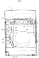
- Fig. 3 is a plan view thereof.
- This combine is a culm-head feeding combine, and includes a crawler-type travel apparatus 1, and a machine body frame 2 supported by the travel apparatus 1.
- the front portion of the machine body frame 2 has a vertically movable harvesting section 3 that cuts standing grain culms.
- a threshing apparatus 11 for threshing cut grain culms and a grain tank 12 for storing grain are arranged side by side in the right-left direction.
- a cabin 13 in which a driver rides is provided in front of the grain tank 12, in the front portion of the machine body frame 2.
- the cabin 13 includes a ceiling panel 14.
- An engine 10 is arranged below the cabin 13.
- the grain tank 12 includes an unloader 15 for unloading grain in the grain tank 12.
- the harvesting section 3 can swing up and down about a swing axis that is oriented horizontally in the right-left orientation.
- the harvesting section 3 includes a raising apparatus 31 for raising standing grain culms, a cutting apparatus 32 for cutting raised grain culms, and a conveying apparatus 33 for conveying cut grain culms to the threshing apparatus 11.
- the cabin 13 includes a driver's seat 130.
- a front panel 131 is provided in front of the driver's seat 130, and a side panel 132 is provided on the left side of the driver's seat 130.
- tools such as a manipulation lever (steering lever) 91 and a meter panel 133 for displaying various types of information are arranged.
- the meter panel 133 displays a meter screen indicating a working speed, engine rotation, a fuel level and the like.
- a monitor 134 such as a liquid crystal panel for graphically displaying specific information is arranged e.g. at an upper left portion inside the cabin 13.
- the monitor 134 displays a selection screen of a target travel route used for automatic working travel and the like.
- a main speed change lever 92 and other tools are arranged on the side panel 132.
- a remote controller 135 for the unloader is arranged on the side panel 132.
- an autopilot ON/OFF switch 90 for giving a command to perform or stop automatic travel is arranged on the side panel 132.
- the autopilot ON/OFF switch 90, as well as other switches, may be replaced with software switches displayed on the monitor 134, or may be provided in both hardware and software forms.
- an own vehicle position detecting box 620 attached to a bracket extending upward from a side end of the ceiling panel 14 is arranged above the cabin 13.
- An antenna, an arithmetic unit and the like used for detecting the own vehicle position are built into the own vehicle position detecting box 620.
- the own vehicle position is detected using satellite navigation and inertial navigation.
- Fig. 5 shows a control system constructed in this combine.
- the control system uses the basic principle described with reference to Fig. 1 , and includes a first vehicle-mounted network 5A and a second vehicle-mounted network 5B.
- the first vehicle-mounted network 5A and the second vehicle-mounted network 5B are bridged via a relay unit 5C.
- functional elements for performing basic operation control of the combine for example, an input signal processing unit 50, a machine body status detecting unit 51, a manual travel control unit 52, a device control unit 53, an engine control unit 54 and a notification unit 55 are constructed.
- a first automatic travel management section 71 is constructed in the first vehicle-mounted network 5A as a constituent element of the automatic travel management section 7 for managing a relationship between manual travel control by the manual travel control unit 52 and automatic travel control by the automatic travel control unit 61; and a second automatic travel management section 72 is constructed in the second vehicle-mounted network 5B as another constituent element of the automatic travel management section 7.
- the device control unit 53 includes a travel device control section 531 that drives various operation devices for traveling (travel devices) by giving them a control signal, and a work device control section 532 that drives various operation devices for working (work devices) by giving them a control signal.
- the travel devices and the work devices in this example are collectively referred to as an operation device 20.
- the engine control unit 54 gives a control signal to the engine 10 for starting and stopping the engine 10, and for adjusting the rotational speed thereof, for example.
- the manual travel operating unit 9 shown in Fig. 5 is a collective term for tools that are manually operated in working travel of the combine, and includes the manipulation lever 91, the main speed change lever 92 and the like.
- this combine employs a by-wire method, and an operation made to the manual travel operating unit 9 is inputted as an operation signal to the input signal processing unit 50.
- the status detecting device 8 is a collective term for various sensors and switches provided in the combine.
- a detection signal from the status detecting device 8 for detecting the status of operation devices including various travel devices and work devices is also essentially inputted to the input signal processing unit 50.
- the machine body status detecting unit 51 can detect various statuses of the combine based on detection signals from the status detecting device 8, and outputs machine body status information indicating such statuses of the combine.
- the machine body status information contains the status of the manipulation lever 91 or the main speed change lever 92, the status of the harvesting section 3, the grain accumulation status of the grain tank 12, the status of a vehicle speed sensor, the status of an emergency stop switch, a difference (the degree of a difference) between a target value and an actual value of various operation devices, or the like.
- the notification unit 55 transmits a notification signal to a notification device 73, thereby notifying it of various types of information that is to be given to a driver and surrounding people.
- the notification device 73 includes not only the above-described monitor 134 but also various lamps inside or outside the machine body (e.g., a notification lamp 731 shown in Figs. 2 and 3 ), a buzzer 732 and the like.
- the manual travel control unit 52 performs arithmetic processing or determination processing, using a signal input through the input signal processing unit 50 or machine body status information from the machine body status detecting unit 51, thereby generating data for controlling an operation of the operation device 20 based on a manual operation.
- the generated data is transmitted to the device control unit 53, and is outputted from the device control unit 53 to the operation device 20 as a control signal. Accordingly, an operation of the operation device 20 corresponding to the manual operation is realized. For example, driving for changing the direction of the travel apparatus 1 is performed based on a direction change output signal, and the machine body traveling direction is changed.
- the own vehicle position detecting module 62 includes a satellite navigation module 621 for detecting a bearing such as latitude and longitude using a GNSS (Global Navigation Satellite System, which may be a GPS (Global Positioning System), and has a configuration similar to that of an orientation measurement unit used in car navigation systems and the like.
- the own vehicle position detecting module 62 in this embodiment includes an inertial navigation module 622 incorporating a gyroscope acceleration sensor and a magnetic bearing sensor for detecting a momentary movement (direction vector, etc.) of the work vehicle and an orientation, for assisting the satellite navigation module 621.
- the outer-shape map calculating section 63 calculates the outer-shape map of cultivated land in which automatic working travel is to be performed. Typically, circulating working while traveling through manual travel is performed along an outer perimeter of a piece of cultivated land in which barley or rice is grown, and an outer-shape map of a work-unfinished region in which automatic working travel is to be performed is calculated from own vehicle position data (own vehicle position information) acquired at that time by the own vehicle position detecting module 62.
- the route calculating section 64 calculates a target travel route along which working travel is to be performed in a work-unfinished region, based on the outer-shape map.
- the automatic travel control unit 61 implements automatic travel, based on automatic travel information necessary for automatic travel.
- the automatic travel information contains deviation between the own vehicle position based on the own vehicle position data and the target travel route, deviation between a travel direction of the own vehicle and a direction obtained by extending the target travel route, a vehicle speed set in advance, an operation of the working machine that needs to be performed during travel along the target travel route, machine body status information from the status detecting device 8,and the like.
- the automatic travel control unit 61 gives the necessary control data to the device control unit 53 based on the automatic travel information, thereby controlling the travel devices and the work devices mounted in the combine.
- the second automatic travel management section 72 that is a constituent element of the automatic travel management section 7 determines forbiddance of automatic travel and permission of the automatic travel by the automatic travel control unit 61 in cooperation with the first automatic travel management section 71 as described above with reference to Fig. 1 ; and based on the machine body status information, the second automatic travel management section 72 outputs a control command in automatic travel forbiddance for deciding control of the machine body to be performed after a command to forbid the automatic travel has been issued.
- the relay unit 5C performs data exchange between the first vehicle-mounted network 5A and the second vehicle-mounted network 5B; and the relay unit 5C itself includes an input/output interface for an external device and a data processing section. Furthermore, the relay unit 5C has a filtering function of selecting a transfer destination of data between the first vehicle-mounted network 5A and the second vehicle-mounted network 5B. Still further, the relay unit 5C has connected thereto the notification lamp 731 and the buzzer 732, each functioning as the notification device 73, and the autopilot ON/OFF switch; and also the relay unit 5C has an automatic travel remote controller 95 wirelessly connected thereto.
- Various types of data can be transmitted via the relay unit 5C from the first vehicle-mounted network 5A to the second vehicle-mounted network 5B, or from the second vehicle-mounted network 5B to the first vehicle-mounted network 5A, but unrestricted data exchange can be restricted by the filtering function of the relay unit 5C.
- the first vehicle-mounted network 5A and the second vehicle-mounted network 5B can be disconnected from each other taking the relay unit 5C as a separation point.
- the first vehicle-mounted network 5A and the second vehicle-mounted network 5B can independently function, and thus a combine including only the first vehicle-mounted network 5A can be driven through manual control, whereas the remaining second vehicle-mounted network 5B can independently perform simulation and the like of driving through automatic control.
- the notification lamp 731 is a cylindrical lamp provided upright on the upper face of the grain tank 12, and may turn on during automatic travel, thereby notifying surrounding people of that the combine is in automatic travel.
- the buzzer 732 can notify surrounding people of that the combine is in automatic travel.
- the autopilot ON/OFF switch 90 is a switch for implementing automatic travel, and automatic travel is not performed unless at least the autopilot ON/OFF switch 90 is ON.
- the automatic travel remote controller 95 is operable to provide, for example, an emergency stop button, an engine start button and an automatic drive button; and from outside the combine to the control system of the combine, the automatic travel remote controller 95 is operable to provide commands to stop the combine in an emergency, to start the engine, and to perform automatic driving.
- the present invention can be applied to work vehicles such as culm-head feeding combines, ordinary combines (whole-culm feeding combines), rice transplanting machines and tractors.
Landscapes
- Engineering & Computer Science (AREA)
- Automation & Control Theory (AREA)
- Mechanical Engineering (AREA)
- Transportation (AREA)
- Life Sciences & Earth Sciences (AREA)
- Environmental Sciences (AREA)
- Human Computer Interaction (AREA)
- Physics & Mathematics (AREA)
- Remote Sensing (AREA)
- Radar, Positioning & Navigation (AREA)
- Aviation & Aerospace Engineering (AREA)
- General Physics & Mathematics (AREA)
- Soil Sciences (AREA)
- Combustion & Propulsion (AREA)
- Chemical & Material Sciences (AREA)
- Mathematical Physics (AREA)
- Guiding Agricultural Machines (AREA)
- Control Of Position, Course, Altitude, Or Attitude Of Moving Bodies (AREA)
- Control Of Driving Devices And Active Controlling Of Vehicle (AREA)
- Business, Economics & Management (AREA)
- Health & Medical Sciences (AREA)
- Artificial Intelligence (AREA)
- Evolutionary Computation (AREA)
- Game Theory and Decision Science (AREA)
- Medical Informatics (AREA)
- Harvester Elements (AREA)
Applications Claiming Priority (2)
| Application Number | Priority Date | Filing Date | Title |
|---|---|---|---|
| JP2015172068A JP6639835B2 (ja) | 2015-09-01 | 2015-09-01 | 走行作業機 |
| PCT/JP2016/065399 WO2017038170A1 (ja) | 2015-09-01 | 2016-05-25 | 走行作業機 |
Publications (3)
| Publication Number | Publication Date |
|---|---|
| EP3345799A1 true EP3345799A1 (de) | 2018-07-11 |
| EP3345799A4 EP3345799A4 (de) | 2019-05-01 |
| EP3345799B1 EP3345799B1 (de) | 2022-08-03 |
Family
ID=58187046
Family Applications (1)
| Application Number | Title | Priority Date | Filing Date |
|---|---|---|---|
| EP16841202.1A Active EP3345799B1 (de) | 2015-09-01 | 2016-05-25 | Fahrarbeitsmaschine |
Country Status (6)
| Country | Link |
|---|---|
| US (1) | US10503169B2 (de) |
| EP (1) | EP3345799B1 (de) |
| JP (1) | JP6639835B2 (de) |
| KR (1) | KR102453276B1 (de) |
| CN (1) | CN107614348B (de) |
| WO (1) | WO2017038170A1 (de) |
Cited By (2)
| Publication number | Priority date | Publication date | Assignee | Title |
|---|---|---|---|---|
| JP2021097618A (ja) * | 2019-12-20 | 2021-07-01 | 株式会社クボタ | 農業機械 |
| EP3847879A3 (de) * | 2019-12-19 | 2021-10-06 | Kubota Corporation | Landwirtschaftliche maschine |
Families Citing this family (20)
| Publication number | Priority date | Publication date | Assignee | Title |
|---|---|---|---|---|
| JP7314874B2 (ja) * | 2015-11-04 | 2023-07-26 | トヨタ自動車株式会社 | 自動運転システム、自動運転装置、自動運転方法 |
| US10372126B2 (en) * | 2016-05-27 | 2019-08-06 | Cnh Industrial America Llc | Dynamic in-cabin autonomous vehicle control systems |
| JP7280934B2 (ja) * | 2017-07-26 | 2023-05-24 | ヤンマーパワーテクノロジー株式会社 | 自動走行システム |
| JP6971075B2 (ja) * | 2017-07-26 | 2021-11-24 | ヤンマーパワーテクノロジー株式会社 | 自動走行システム |
| JP6938279B2 (ja) * | 2017-08-29 | 2021-09-22 | 株式会社クボタ | 作業機の自動走行システム |
| WO2019080067A1 (zh) * | 2017-10-26 | 2019-05-02 | 深圳市大疆创新科技有限公司 | 农用机控制方法、装置及系统 |
| US11738643B2 (en) | 2019-02-27 | 2023-08-29 | Clark Equipment Company | Display integrated into door |
| ES2967296T3 (es) | 2018-08-06 | 2024-04-29 | Doosan Bobcat North America Inc | Controles aumentados de pala cargadora |
| JP7040705B2 (ja) * | 2019-01-31 | 2022-03-23 | ヤンマーパワーテクノロジー株式会社 | 作業車両の自動走行システム |
| WO2020262416A1 (ja) * | 2019-06-28 | 2020-12-30 | 株式会社クボタ | 自動走行システム、農作業機、プログラム、プログラムを記録した記録媒体、及び方法 |
| KR102315678B1 (ko) | 2019-07-05 | 2021-10-21 | 엘지전자 주식회사 | 잔디 깎기 로봇 및 그 제어 방법 |
| JP6766240B1 (ja) * | 2019-09-06 | 2020-10-07 | 株式会社クボタ | 作業車両 |
| US11648887B2 (en) | 2019-11-12 | 2023-05-16 | Clark Equipment Company | Display integrated into door |
| JP7189121B2 (ja) * | 2019-12-19 | 2022-12-13 | 株式会社クボタ | 作業車両 |
| JP7301736B2 (ja) | 2019-12-27 | 2023-07-03 | 株式会社クボタ | 作業車両 |
| JP6944510B2 (ja) * | 2019-12-27 | 2021-10-06 | 本田技研工業株式会社 | 車両制御装置、車両及び車両制御方法 |
| CN113678623A (zh) * | 2020-05-18 | 2021-11-23 | 株式会社久保田 | 联合收割机 |
| KR102382114B1 (ko) * | 2020-08-05 | 2022-04-05 | 한양대학교 에리카산학협력단 | 자율주행 차량의 판단 시스템 |
| WO2022049890A1 (ja) * | 2020-09-04 | 2022-03-10 | 株式会社小松製作所 | 作業機械、作業機械を制御するための方法、及びシステム |
| JP7434127B2 (ja) * | 2020-09-16 | 2024-02-20 | 株式会社クボタ | 作業機 |
Family Cites Families (20)
| Publication number | Priority date | Publication date | Assignee | Title |
|---|---|---|---|---|
| GB2191649A (en) | 1986-06-10 | 1987-12-16 | Philips Electronic Associated | Radio direction-finding |
| JPH06336170A (ja) * | 1993-05-27 | 1994-12-06 | Fuji Heavy Ind Ltd | 自動操舵装置の制御方法 |
| JPH09128044A (ja) * | 1995-11-02 | 1997-05-16 | Hitachi Ltd | 走行作業機械の半自動制御方式 |
| JP3171119B2 (ja) | 1995-12-04 | 2001-05-28 | トヨタ自動車株式会社 | 車両の自動運転制御装置 |
| JPH10147952A (ja) | 1996-11-18 | 1998-06-02 | Komatsu Ltd | ブルドーザのドージング装置 |
| JP2002175597A (ja) * | 2000-12-07 | 2002-06-21 | Hitachi Ltd | 自動車の走行制御システム |
| US6633800B1 (en) * | 2001-01-31 | 2003-10-14 | Ainsworth Inc. | Remote control system |
| US7574290B2 (en) | 2004-11-30 | 2009-08-11 | Trimble Navigation Limited | Method and system for implementing automatic vehicle control with parameter-driven disengagement |
| US20070293989A1 (en) * | 2006-06-14 | 2007-12-20 | Deere & Company, A Delaware Corporation | Multiple mode system with multiple controllers |
| EP1967931A3 (de) * | 2007-03-06 | 2013-10-30 | Yamaha Hatsudoki Kabushiki Kaisha | Fahrzeug |
| US9605409B2 (en) * | 2009-03-31 | 2017-03-28 | Caterpillar Inc. | System and method for operating a machine |
| JP2012023997A (ja) * | 2010-07-21 | 2012-02-09 | National Agriculture & Food Research Organization | 作業車両の自動走行制御装置 |
| EP2751630B1 (de) * | 2011-08-29 | 2019-03-13 | Crown Equipment Corporation | Fahrzeugnavigations-steuerschnittstelle |
| FR2989047B1 (fr) | 2012-04-05 | 2014-04-11 | Renault Sa | Systeme de commande de vehicule en mode autonome et vehicule comprenant un tel systeme de commande |
| US8825258B2 (en) * | 2012-11-30 | 2014-09-02 | Google Inc. | Engaging and disengaging for autonomous driving |
| JP6016680B2 (ja) * | 2013-03-18 | 2016-10-26 | ヤンマー株式会社 | 走行車両 |
| US9342074B2 (en) * | 2013-04-05 | 2016-05-17 | Google Inc. | Systems and methods for transitioning control of an autonomous vehicle to a driver |
| JP6155973B2 (ja) * | 2013-08-27 | 2017-07-05 | 株式会社デンソー | 運転支援装置、および運転支援方法 |
| US9465388B1 (en) * | 2014-03-03 | 2016-10-11 | Google Inc. | Remote assistance for an autonomous vehicle in low confidence situations |
| KR20160139019A (ko) * | 2014-03-28 | 2016-12-06 | 얀마 가부시키가이샤 | 자율 주행 작업 차량 |
-
2015
- 2015-09-01 JP JP2015172068A patent/JP6639835B2/ja active Active
-
2016
- 2016-05-25 EP EP16841202.1A patent/EP3345799B1/de active Active
- 2016-05-25 CN CN201680030135.XA patent/CN107614348B/zh active Active
- 2016-05-25 US US15/579,292 patent/US10503169B2/en active Active
- 2016-05-25 KR KR1020177032880A patent/KR102453276B1/ko active IP Right Grant
- 2016-05-25 WO PCT/JP2016/065399 patent/WO2017038170A1/ja active Application Filing
Cited By (3)
| Publication number | Priority date | Publication date | Assignee | Title |
|---|---|---|---|---|
| EP3847879A3 (de) * | 2019-12-19 | 2021-10-06 | Kubota Corporation | Landwirtschaftliche maschine |
| US11726486B2 (en) | 2019-12-19 | 2023-08-15 | Kubota Corporation | Agricultural machine |
| JP2021097618A (ja) * | 2019-12-20 | 2021-07-01 | 株式会社クボタ | 農業機械 |
Also Published As
| Publication number | Publication date |
|---|---|
| WO2017038170A1 (ja) | 2017-03-09 |
| JP6639835B2 (ja) | 2020-02-05 |
| US10503169B2 (en) | 2019-12-10 |
| EP3345799B1 (de) | 2022-08-03 |
| KR102453276B1 (ko) | 2022-10-11 |
| EP3345799A4 (de) | 2019-05-01 |
| US20180299894A1 (en) | 2018-10-18 |
| CN107614348A (zh) | 2018-01-19 |
| KR20180048451A (ko) | 2018-05-10 |
| JP2017047762A (ja) | 2017-03-09 |
| CN107614348B (zh) | 2020-11-06 |
Similar Documents
| Publication | Publication Date | Title |
|---|---|---|
| EP3345799B1 (de) | Fahrarbeitsmaschine | |
| EP3351075B1 (de) | Stützsystem für arbeitsfahrzeug | |
| CN108334066B (zh) | 作业行驶管理系统 | |
| US11197405B2 (en) | Harvesting machine and travel mode switching method | |
| US10474153B2 (en) | Work vehicle, slope travel control system for work vehicle, and slope travel control method for work vehicle | |
| CN113826460B (zh) | 作业车辆 | |
| KR101974768B1 (ko) | 작업 차량 및 작업 차량을 자동 주행시키는 주행 제어 장치 | |
| US10732628B2 (en) | Sensor management device and sensor management method | |
| EP3146823B1 (de) | Betriebssystem für ein arbeitsfahrzeug | |
| JP7357444B2 (ja) | 収穫機 | |
| KR102113415B1 (ko) | 작업 차량 제어 시스템 | |
| JP6937676B2 (ja) | 収穫機 | |
| EP3854191A1 (de) | Feldarbeitsfahrzeug | |
| JP6925133B2 (ja) | 作業車のための衛星電波感度分布管理システム | |
| JP6708724B2 (ja) | 自律走行システム | |
| JP7109300B2 (ja) | 収穫機 | |
| JP7503844B2 (ja) | 作業車両の遠隔制御システム、遠隔操作装置および遠隔制御方法 | |
| JP2020129408A (ja) | 自律走行システム | |
| JP7076524B2 (ja) | 作業走行管理システム及び作業走行管理装置 | |
| JP2021074016A (ja) | 作業車及び作業車のための傾斜走行管理システム |
Legal Events
| Date | Code | Title | Description |
|---|---|---|---|
| STAA | Information on the status of an ep patent application or granted ep patent |
Free format text: STATUS: THE INTERNATIONAL PUBLICATION HAS BEEN MADE |
|
| PUAI | Public reference made under article 153(3) epc to a published international application that has entered the european phase |
Free format text: ORIGINAL CODE: 0009012 |
|
| STAA | Information on the status of an ep patent application or granted ep patent |
Free format text: STATUS: REQUEST FOR EXAMINATION WAS MADE |
|
| 17P | Request for examination filed |
Effective date: 20171205 |
|
| AK | Designated contracting states |
Kind code of ref document: A1 Designated state(s): AL AT BE BG CH CY CZ DE DK EE ES FI FR GB GR HR HU IE IS IT LI LT LU LV MC MK MT NL NO PL PT RO RS SE SI SK SM TR |
|
| AX | Request for extension of the european patent |
Extension state: BA ME |
|
| DAV | Request for validation of the european patent (deleted) | ||
| DAX | Request for extension of the european patent (deleted) | ||
| A4 | Supplementary search report drawn up and despatched |
Effective date: 20190401 |
|
| RIC1 | Information provided on ipc code assigned before grant |
Ipc: B60W 40/12 20120101ALI20190326BHEP Ipc: B60W 50/02 20120101AFI20190326BHEP Ipc: A01B 69/00 20060101ALI20190326BHEP Ipc: B60W 50/00 20060101ALN20190326BHEP Ipc: B60W 50/10 20120101ALI20190326BHEP Ipc: B60W 50/038 20120101ALI20190326BHEP Ipc: G05D 1/00 20060101ALI20190326BHEP Ipc: A01B 69/04 20060101ALI20190326BHEP Ipc: B60W 30/18 20120101ALI20190326BHEP Ipc: A01D 41/127 20060101ALI20190326BHEP |
|
| GRAP | Despatch of communication of intention to grant a patent |
Free format text: ORIGINAL CODE: EPIDOSNIGR1 |
|
| STAA | Information on the status of an ep patent application or granted ep patent |
Free format text: STATUS: GRANT OF PATENT IS INTENDED |
|
| RIC1 | Information provided on ipc code assigned before grant |
Ipc: B60W 50/00 20060101ALN20220317BHEP Ipc: B60W 60/00 20200101ALI20220317BHEP Ipc: B60W 50/10 20120101ALI20220317BHEP Ipc: A01B 69/04 20060101ALI20220317BHEP Ipc: G05D 1/00 20060101ALI20220317BHEP Ipc: A01D 41/127 20060101ALI20220317BHEP Ipc: B60W 50/038 20120101ALI20220317BHEP Ipc: B60W 40/12 20120101ALI20220317BHEP Ipc: B60W 30/18 20120101ALI20220317BHEP Ipc: A01B 69/00 20060101ALI20220317BHEP Ipc: B60W 50/02 20120101AFI20220317BHEP |
|
| INTG | Intention to grant announced |
Effective date: 20220420 |
|
| GRAS | Grant fee paid |
Free format text: ORIGINAL CODE: EPIDOSNIGR3 |
|
| GRAA | (expected) grant |
Free format text: ORIGINAL CODE: 0009210 |
|
| STAA | Information on the status of an ep patent application or granted ep patent |
Free format text: STATUS: THE PATENT HAS BEEN GRANTED |
|
| AK | Designated contracting states |
Kind code of ref document: B1 Designated state(s): AL AT BE BG CH CY CZ DE DK EE ES FI FR GB GR HR HU IE IS IT LI LT LU LV MC MK MT NL NO PL PT RO RS SE SI SK SM TR |
|
| REG | Reference to a national code |
Ref country code: AT Ref legal event code: REF Ref document number: 1508519 Country of ref document: AT Kind code of ref document: T Effective date: 20220815 Ref country code: CH Ref legal event code: EP |
|
| REG | Reference to a national code |
Ref country code: DE Ref legal event code: R096 Ref document number: 602016074027 Country of ref document: DE |
|
| REG | Reference to a national code |
Ref country code: IE Ref legal event code: FG4D |
|
| REG | Reference to a national code |
Ref country code: LT Ref legal event code: MG9D |
|
| REG | Reference to a national code |
Ref country code: NL Ref legal event code: MP Effective date: 20220803 |
|
| PG25 | Lapsed in a contracting state [announced via postgrant information from national office to epo] |
Ref country code: SE Free format text: LAPSE BECAUSE OF FAILURE TO SUBMIT A TRANSLATION OF THE DESCRIPTION OR TO PAY THE FEE WITHIN THE PRESCRIBED TIME-LIMIT Effective date: 20220803 Ref country code: RS Free format text: LAPSE BECAUSE OF FAILURE TO SUBMIT A TRANSLATION OF THE DESCRIPTION OR TO PAY THE FEE WITHIN THE PRESCRIBED TIME-LIMIT Effective date: 20220803 Ref country code: PT Free format text: LAPSE BECAUSE OF FAILURE TO SUBMIT A TRANSLATION OF THE DESCRIPTION OR TO PAY THE FEE WITHIN THE PRESCRIBED TIME-LIMIT Effective date: 20221205 Ref country code: NO Free format text: LAPSE BECAUSE OF FAILURE TO SUBMIT A TRANSLATION OF THE DESCRIPTION OR TO PAY THE FEE WITHIN THE PRESCRIBED TIME-LIMIT Effective date: 20221103 Ref country code: NL Free format text: LAPSE BECAUSE OF FAILURE TO SUBMIT A TRANSLATION OF THE DESCRIPTION OR TO PAY THE FEE WITHIN THE PRESCRIBED TIME-LIMIT Effective date: 20220803 Ref country code: LV Free format text: LAPSE BECAUSE OF FAILURE TO SUBMIT A TRANSLATION OF THE DESCRIPTION OR TO PAY THE FEE WITHIN THE PRESCRIBED TIME-LIMIT Effective date: 20220803 Ref country code: LT Free format text: LAPSE BECAUSE OF FAILURE TO SUBMIT A TRANSLATION OF THE DESCRIPTION OR TO PAY THE FEE WITHIN THE PRESCRIBED TIME-LIMIT Effective date: 20220803 Ref country code: FI Free format text: LAPSE BECAUSE OF FAILURE TO SUBMIT A TRANSLATION OF THE DESCRIPTION OR TO PAY THE FEE WITHIN THE PRESCRIBED TIME-LIMIT Effective date: 20220803 Ref country code: ES Free format text: LAPSE BECAUSE OF FAILURE TO SUBMIT A TRANSLATION OF THE DESCRIPTION OR TO PAY THE FEE WITHIN THE PRESCRIBED TIME-LIMIT Effective date: 20220803 |
|
| REG | Reference to a national code |
Ref country code: AT Ref legal event code: MK05 Ref document number: 1508519 Country of ref document: AT Kind code of ref document: T Effective date: 20220803 |
|
| PG25 | Lapsed in a contracting state [announced via postgrant information from national office to epo] |
Ref country code: PL Free format text: LAPSE BECAUSE OF FAILURE TO SUBMIT A TRANSLATION OF THE DESCRIPTION OR TO PAY THE FEE WITHIN THE PRESCRIBED TIME-LIMIT Effective date: 20220803 Ref country code: IS Free format text: LAPSE BECAUSE OF FAILURE TO SUBMIT A TRANSLATION OF THE DESCRIPTION OR TO PAY THE FEE WITHIN THE PRESCRIBED TIME-LIMIT Effective date: 20221203 Ref country code: HR Free format text: LAPSE BECAUSE OF FAILURE TO SUBMIT A TRANSLATION OF THE DESCRIPTION OR TO PAY THE FEE WITHIN THE PRESCRIBED TIME-LIMIT Effective date: 20220803 Ref country code: GR Free format text: LAPSE BECAUSE OF FAILURE TO SUBMIT A TRANSLATION OF THE DESCRIPTION OR TO PAY THE FEE WITHIN THE PRESCRIBED TIME-LIMIT Effective date: 20221104 |
|
| REG | Reference to a national code |
Ref country code: DE Ref legal event code: R082 Ref document number: 602016074027 Country of ref document: DE Representative=s name: CBDL PATENTANWAELTE GBR, DE |
|
| PG25 | Lapsed in a contracting state [announced via postgrant information from national office to epo] |
Ref country code: SM Free format text: LAPSE BECAUSE OF FAILURE TO SUBMIT A TRANSLATION OF THE DESCRIPTION OR TO PAY THE FEE WITHIN THE PRESCRIBED TIME-LIMIT Effective date: 20220803 Ref country code: RO Free format text: LAPSE BECAUSE OF FAILURE TO SUBMIT A TRANSLATION OF THE DESCRIPTION OR TO PAY THE FEE WITHIN THE PRESCRIBED TIME-LIMIT Effective date: 20220803 Ref country code: DK Free format text: LAPSE BECAUSE OF FAILURE TO SUBMIT A TRANSLATION OF THE DESCRIPTION OR TO PAY THE FEE WITHIN THE PRESCRIBED TIME-LIMIT Effective date: 20220803 Ref country code: CZ Free format text: LAPSE BECAUSE OF FAILURE TO SUBMIT A TRANSLATION OF THE DESCRIPTION OR TO PAY THE FEE WITHIN THE PRESCRIBED TIME-LIMIT Effective date: 20220803 Ref country code: AT Free format text: LAPSE BECAUSE OF FAILURE TO SUBMIT A TRANSLATION OF THE DESCRIPTION OR TO PAY THE FEE WITHIN THE PRESCRIBED TIME-LIMIT Effective date: 20220803 |
|
| REG | Reference to a national code |
Ref country code: DE Ref legal event code: R097 Ref document number: 602016074027 Country of ref document: DE |
|
| PG25 | Lapsed in a contracting state [announced via postgrant information from national office to epo] |
Ref country code: SK Free format text: LAPSE BECAUSE OF FAILURE TO SUBMIT A TRANSLATION OF THE DESCRIPTION OR TO PAY THE FEE WITHIN THE PRESCRIBED TIME-LIMIT Effective date: 20220803 Ref country code: EE Free format text: LAPSE BECAUSE OF FAILURE TO SUBMIT A TRANSLATION OF THE DESCRIPTION OR TO PAY THE FEE WITHIN THE PRESCRIBED TIME-LIMIT Effective date: 20220803 |
|
| PLBE | No opposition filed within time limit |
Free format text: ORIGINAL CODE: 0009261 |
|
| STAA | Information on the status of an ep patent application or granted ep patent |
Free format text: STATUS: NO OPPOSITION FILED WITHIN TIME LIMIT |
|
| PG25 | Lapsed in a contracting state [announced via postgrant information from national office to epo] |
Ref country code: AL Free format text: LAPSE BECAUSE OF FAILURE TO SUBMIT A TRANSLATION OF THE DESCRIPTION OR TO PAY THE FEE WITHIN THE PRESCRIBED TIME-LIMIT Effective date: 20220803 |
|
| 26N | No opposition filed |
Effective date: 20230504 |
|
| PG25 | Lapsed in a contracting state [announced via postgrant information from national office to epo] |
Ref country code: SI Free format text: LAPSE BECAUSE OF FAILURE TO SUBMIT A TRANSLATION OF THE DESCRIPTION OR TO PAY THE FEE WITHIN THE PRESCRIBED TIME-LIMIT Effective date: 20220803 |
|
| REG | Reference to a national code |
Ref country code: CH Ref legal event code: PL |
|
| PG25 | Lapsed in a contracting state [announced via postgrant information from national office to epo] |
Ref country code: MC Free format text: LAPSE BECAUSE OF FAILURE TO SUBMIT A TRANSLATION OF THE DESCRIPTION OR TO PAY THE FEE WITHIN THE PRESCRIBED TIME-LIMIT Effective date: 20220803 |
|
| GBPC | Gb: european patent ceased through non-payment of renewal fee |
Effective date: 20230525 |
|
| REG | Reference to a national code |
Ref country code: BE Ref legal event code: MM Effective date: 20230531 |
|
| PG25 | Lapsed in a contracting state [announced via postgrant information from national office to epo] |
Ref country code: MC Free format text: LAPSE BECAUSE OF FAILURE TO SUBMIT A TRANSLATION OF THE DESCRIPTION OR TO PAY THE FEE WITHIN THE PRESCRIBED TIME-LIMIT Effective date: 20220803 Ref country code: LU Free format text: LAPSE BECAUSE OF NON-PAYMENT OF DUE FEES Effective date: 20230525 Ref country code: LI Free format text: LAPSE BECAUSE OF NON-PAYMENT OF DUE FEES Effective date: 20230531 Ref country code: CH Free format text: LAPSE BECAUSE OF NON-PAYMENT OF DUE FEES Effective date: 20230531 |
|
| REG | Reference to a national code |
Ref country code: IE Ref legal event code: MM4A |
|
| PG25 | Lapsed in a contracting state [announced via postgrant information from national office to epo] |
Ref country code: IE Free format text: LAPSE BECAUSE OF NON-PAYMENT OF DUE FEES Effective date: 20230525 |
|
| PG25 | Lapsed in a contracting state [announced via postgrant information from national office to epo] |
Ref country code: IE Free format text: LAPSE BECAUSE OF NON-PAYMENT OF DUE FEES Effective date: 20230525 Ref country code: GB Free format text: LAPSE BECAUSE OF NON-PAYMENT OF DUE FEES Effective date: 20230525 |
|
| PG25 | Lapsed in a contracting state [announced via postgrant information from national office to epo] |
Ref country code: IT Free format text: LAPSE BECAUSE OF FAILURE TO SUBMIT A TRANSLATION OF THE DESCRIPTION OR TO PAY THE FEE WITHIN THE PRESCRIBED TIME-LIMIT Effective date: 20220803 Ref country code: FR Free format text: LAPSE BECAUSE OF NON-PAYMENT OF DUE FEES Effective date: 20230531 Ref country code: BE Free format text: LAPSE BECAUSE OF NON-PAYMENT OF DUE FEES Effective date: 20230531 |
|
| PGFP | Annual fee paid to national office [announced via postgrant information from national office to epo] |
Ref country code: DE Payment date: 20240328 Year of fee payment: 9 |