EP3343213B1 - Sensor - Google Patents
Sensor Download PDFInfo
- Publication number
- EP3343213B1 EP3343213B1 EP18151485.2A EP18151485A EP3343213B1 EP 3343213 B1 EP3343213 B1 EP 3343213B1 EP 18151485 A EP18151485 A EP 18151485A EP 3343213 B1 EP3343213 B1 EP 3343213B1
- Authority
- EP
- European Patent Office
- Prior art keywords
- sensor
- mediator
- enzyme
- electrode
- potential
- Prior art date
- Legal status (The legal status is an assumption and is not a legal conclusion. Google has not performed a legal analysis and makes no representation as to the accuracy of the status listed.)
- Active
Links
- 102000004190 Enzymes Human genes 0.000 claims description 64
- 108090000790 Enzymes Proteins 0.000 claims description 64
- -1 quinone compound Chemical class 0.000 claims description 48
- 239000013076 target substance Substances 0.000 claims description 41
- 239000008280 blood Substances 0.000 claims description 35
- 210000004369 blood Anatomy 0.000 claims description 35
- 239000007788 liquid Substances 0.000 claims description 31
- AZQWKYJCGOJGHM-UHFFFAOYSA-N para-benzoquinone Natural products O=C1C=CC(=O)C=C1 AZQWKYJCGOJGHM-UHFFFAOYSA-N 0.000 claims description 30
- CIWBSHSKHKDKBQ-JLAZNSOCSA-N Ascorbic acid Chemical compound OC[C@H](O)[C@H]1OC(=O)C(O)=C1O CIWBSHSKHKDKBQ-JLAZNSOCSA-N 0.000 claims description 28
- 239000005515 coenzyme Substances 0.000 claims description 26
- 230000001419 dependent effect Effects 0.000 claims description 22
- 238000007254 oxidation reaction Methods 0.000 claims description 15
- 235000010323 ascorbic acid Nutrition 0.000 claims description 13
- 239000011668 ascorbic acid Substances 0.000 claims description 13
- 229960005070 ascorbic acid Drugs 0.000 claims description 13
- 229910021607 Silver chloride Inorganic materials 0.000 claims description 8
- 108010050375 Glucose 1-Dehydrogenase Proteins 0.000 claims description 7
- 229910052709 silver Inorganic materials 0.000 claims description 3
- 239000004332 silver Substances 0.000 claims description 3
- 238000006356 dehydrogenation reaction Methods 0.000 claims 1
- 238000005259 measurement Methods 0.000 description 60
- 229940088598 enzyme Drugs 0.000 description 55
- WQZGKKKJIJFFOK-GASJEMHNSA-N Glucose Natural products OC[C@H]1OC(O)[C@H](O)[C@@H](O)[C@@H]1O WQZGKKKJIJFFOK-GASJEMHNSA-N 0.000 description 48
- 239000008103 glucose Substances 0.000 description 48
- 239000003153 chemical reaction reagent Substances 0.000 description 47
- 239000000523 sample Substances 0.000 description 35
- 239000000126 substance Substances 0.000 description 34
- DGAQECJNVWCQMB-PUAWFVPOSA-M Ilexoside XXIX Chemical compound C[C@@H]1CC[C@@]2(CC[C@@]3(C(=CC[C@H]4[C@]3(CC[C@@H]5[C@@]4(CC[C@@H](C5(C)C)OS(=O)(=O)[O-])C)C)[C@@H]2[C@]1(C)O)C)C(=O)O[C@H]6[C@@H]([C@H]([C@@H]([C@H](O6)CO)O)O)O.[Na+] DGAQECJNVWCQMB-PUAWFVPOSA-M 0.000 description 28
- 229910052708 sodium Inorganic materials 0.000 description 28
- 239000011734 sodium Substances 0.000 description 28
- 239000000758 substrate Substances 0.000 description 27
- MMXZSJMASHPLLR-UHFFFAOYSA-N pyrroloquinoline quinone Chemical compound C12=C(C(O)=O)C=C(C(O)=O)N=C2C(=O)C(=O)C2=C1NC(C(=O)O)=C2 MMXZSJMASHPLLR-UHFFFAOYSA-N 0.000 description 25
- 230000002452 interceptive effect Effects 0.000 description 21
- 238000006243 chemical reaction Methods 0.000 description 20
- 230000000694 effects Effects 0.000 description 17
- 125000006850 spacer group Chemical group 0.000 description 16
- 230000006870 function Effects 0.000 description 14
- 230000003647 oxidation Effects 0.000 description 13
- KDLHZDBZIXYQEI-UHFFFAOYSA-N Palladium Chemical compound [Pd] KDLHZDBZIXYQEI-UHFFFAOYSA-N 0.000 description 12
- 239000007864 aqueous solution Substances 0.000 description 10
- 230000004044 response Effects 0.000 description 10
- 239000000243 solution Substances 0.000 description 10
- RZVAJINKPMORJF-UHFFFAOYSA-N Acetaminophen Chemical compound CC(=O)NC1=CC=C(O)C=C1 RZVAJINKPMORJF-UHFFFAOYSA-N 0.000 description 8
- 239000000872 buffer Substances 0.000 description 8
- 239000002904 solvent Substances 0.000 description 8
- YYVYAPXYZVYDHN-UHFFFAOYSA-N 9,10-phenanthroquinone Chemical compound C1=CC=C2C(=O)C(=O)C3=CC=CC=C3C2=C1 YYVYAPXYZVYDHN-UHFFFAOYSA-N 0.000 description 7
- 238000000034 method Methods 0.000 description 7
- 230000001590 oxidative effect Effects 0.000 description 7
- 238000006722 reduction reaction Methods 0.000 description 7
- XLYOFNOQVPJJNP-UHFFFAOYSA-N water Substances O XLYOFNOQVPJJNP-UHFFFAOYSA-N 0.000 description 7
- 238000002484 cyclic voltammetry Methods 0.000 description 6
- 230000002349 favourable effect Effects 0.000 description 6
- 229910052763 palladium Inorganic materials 0.000 description 6
- 239000007991 ACES buffer Substances 0.000 description 5
- 108090000854 Oxidoreductases Proteins 0.000 description 5
- 102000004316 Oxidoreductases Human genes 0.000 description 5
- 239000012472 biological sample Substances 0.000 description 5
- 239000003638 chemical reducing agent Substances 0.000 description 5
- 239000004020 conductor Substances 0.000 description 5
- 238000012937 correction Methods 0.000 description 5
- 238000001514 detection method Methods 0.000 description 5
- 150000002500 ions Chemical class 0.000 description 5
- JVTAAEKCZFNVCJ-UHFFFAOYSA-N lactic acid Chemical group CC(O)C(O)=O JVTAAEKCZFNVCJ-UHFFFAOYSA-N 0.000 description 5
- 239000000203 mixture Substances 0.000 description 5
- 239000007800 oxidant agent Substances 0.000 description 5
- 239000008363 phosphate buffer Substances 0.000 description 5
- 230000009467 reduction Effects 0.000 description 5
- HKZLPVFGJNLROG-UHFFFAOYSA-M silver monochloride Chemical compound [Cl-].[Ag+] HKZLPVFGJNLROG-UHFFFAOYSA-M 0.000 description 5
- 239000001509 sodium citrate Substances 0.000 description 5
- HRXKRNGNAMMEHJ-UHFFFAOYSA-K trisodium citrate Chemical compound [Na+].[Na+].[Na+].[O-]C(=O)CC(O)(CC([O-])=O)C([O-])=O HRXKRNGNAMMEHJ-UHFFFAOYSA-K 0.000 description 5
- 229940038773 trisodium citrate Drugs 0.000 description 5
- ZLMJMSJWJFRBEC-UHFFFAOYSA-N Potassium Chemical compound [K] ZLMJMSJWJFRBEC-UHFFFAOYSA-N 0.000 description 4
- YAGKRVSRTSUGEY-UHFFFAOYSA-N ferricyanide Chemical compound [Fe+3].N#[C-].N#[C-].N#[C-].N#[C-].N#[C-].N#[C-] YAGKRVSRTSUGEY-UHFFFAOYSA-N 0.000 description 4
- 238000005534 hematocrit Methods 0.000 description 4
- 239000000463 material Substances 0.000 description 4
- 229960005489 paracetamol Drugs 0.000 description 4
- 229910052700 potassium Inorganic materials 0.000 description 4
- 239000011591 potassium Substances 0.000 description 4
- DGEZNRSVGBDHLK-UHFFFAOYSA-N [1,10]phenanthroline Chemical compound C1=CN=C2C3=NC=CC=C3C=CC2=C1 DGEZNRSVGBDHLK-UHFFFAOYSA-N 0.000 description 3
- QVGXLLKOCUKJST-UHFFFAOYSA-N atomic oxygen Chemical compound [O] QVGXLLKOCUKJST-UHFFFAOYSA-N 0.000 description 3
- 230000008901 benefit Effects 0.000 description 3
- 239000011248 coating agent Substances 0.000 description 3
- 238000000576 coating method Methods 0.000 description 3
- 238000001035 drying Methods 0.000 description 3
- 235000014655 lactic acid Nutrition 0.000 description 3
- 239000004310 lactic acid Substances 0.000 description 3
- 238000000608 laser ablation Methods 0.000 description 3
- 238000004519 manufacturing process Methods 0.000 description 3
- 238000000691 measurement method Methods 0.000 description 3
- 229910052760 oxygen Inorganic materials 0.000 description 3
- 239000001301 oxygen Substances 0.000 description 3
- BASFCYQUMIYNBI-UHFFFAOYSA-N platinum Chemical compound [Pt] BASFCYQUMIYNBI-UHFFFAOYSA-N 0.000 description 3
- 150000004059 quinone derivatives Chemical class 0.000 description 3
- FRASJONUBLZVQX-UHFFFAOYSA-N 1,4-naphthoquinone Chemical compound C1=CC=C2C(=O)C=CC(=O)C2=C1 FRASJONUBLZVQX-UHFFFAOYSA-N 0.000 description 2
- QIXDHVDGPXBRRD-UHFFFAOYSA-N 2,3,5-trimethylcyclohexa-2,5-diene-1,4-dione Chemical compound CC1=CC(=O)C(C)=C(C)C1=O QIXDHVDGPXBRRD-UHFFFAOYSA-N 0.000 description 2
- MYKLQMNSFPAPLZ-UHFFFAOYSA-N 2,5-dimethylcyclohexa-2,5-diene-1,4-dione Chemical compound CC1=CC(=O)C(C)=CC1=O MYKLQMNSFPAPLZ-UHFFFAOYSA-N 0.000 description 2
- BPYKTIZUTYGOLE-IFADSCNNSA-N Bilirubin Chemical group N1C(=O)C(C)=C(C=C)\C1=C\C1=C(C)C(CCC(O)=O)=C(CC2=C(C(C)=C(\C=C/3C(=C(C=C)C(=O)N\3)C)N2)CCC(O)=O)N1 BPYKTIZUTYGOLE-IFADSCNNSA-N 0.000 description 2
- 101710088194 Dehydrogenase Proteins 0.000 description 2
- 108020005199 Dehydrogenases Proteins 0.000 description 2
- MJVAVZPDRWSRRC-UHFFFAOYSA-N Menadione Chemical compound C1=CC=C2C(=O)C(C)=CC(=O)C2=C1 MJVAVZPDRWSRRC-UHFFFAOYSA-N 0.000 description 2
- 230000009471 action Effects 0.000 description 2
- 239000011230 binding agent Substances 0.000 description 2
- 230000015572 biosynthetic process Effects 0.000 description 2
- 230000008859 change Effects 0.000 description 2
- HVYWMOMLDIMFJA-DPAQBDIFSA-N cholesterol Chemical compound C1C=C2C[C@@H](O)CC[C@]2(C)[C@@H]2[C@@H]1[C@@H]1CC[C@H]([C@H](C)CCCC(C)C)[C@@]1(C)CC2 HVYWMOMLDIMFJA-DPAQBDIFSA-N 0.000 description 2
- 230000000052 comparative effect Effects 0.000 description 2
- 229920001940 conductive polymer Polymers 0.000 description 2
- 238000007599 discharging Methods 0.000 description 2
- 238000003487 electrochemical reaction Methods 0.000 description 2
- 239000000945 filler Substances 0.000 description 2
- 125000000524 functional group Chemical group 0.000 description 2
- 229910021397 glassy carbon Inorganic materials 0.000 description 2
- 125000002791 glucosyl group Chemical group C1([C@H](O)[C@@H](O)[C@H](O)[C@H](O1)CO)* 0.000 description 2
- CSFWPUWCSPOLJW-UHFFFAOYSA-N lawsone Chemical compound C1=CC=C2C(=O)C(O)=CC(=O)C2=C1 CSFWPUWCSPOLJW-UHFFFAOYSA-N 0.000 description 2
- 229910052751 metal Inorganic materials 0.000 description 2
- 239000002184 metal Substances 0.000 description 2
- 239000012476 oxidizable substance Substances 0.000 description 2
- 229920000139 polyethylene terephthalate Polymers 0.000 description 2
- 239000005020 polyethylene terephthalate Substances 0.000 description 2
- 230000009257 reactivity Effects 0.000 description 2
- 230000035945 sensitivity Effects 0.000 description 2
- 238000004544 sputter deposition Methods 0.000 description 2
- 210000002700 urine Anatomy 0.000 description 2
- PZTGRDMCBZUJDL-UHFFFAOYSA-N 1,2-naphthoquinone-4-sulfonic acid Chemical compound C1=CC=C2C(S(=O)(=O)O)=CC(=O)C(=O)C2=C1 PZTGRDMCBZUJDL-UHFFFAOYSA-N 0.000 description 1
- SVPKNMBRVBMTLB-UHFFFAOYSA-N 2,3-dichloronaphthalene-1,4-dione Chemical compound C1=CC=C2C(=O)C(Cl)=C(Cl)C(=O)C2=C1 SVPKNMBRVBMTLB-UHFFFAOYSA-N 0.000 description 1
- HVGWDVJUMODUIZ-UHFFFAOYSA-N 2-methoxy-6-methylcyclohexa-2,5-diene-1,4-dione Chemical compound COC1=CC(=O)C=C(C)C1=O HVGWDVJUMODUIZ-UHFFFAOYSA-N 0.000 description 1
- 108010025188 Alcohol oxidase Proteins 0.000 description 1
- 108010015428 Bilirubin oxidase Proteins 0.000 description 1
- UXVMQQNJUSDDNG-UHFFFAOYSA-L Calcium chloride Chemical compound [Cl-].[Cl-].[Ca+2] UXVMQQNJUSDDNG-UHFFFAOYSA-L 0.000 description 1
- OKTJSMMVPCPJKN-UHFFFAOYSA-N Carbon Chemical compound [C] OKTJSMMVPCPJKN-UHFFFAOYSA-N 0.000 description 1
- 239000004215 Carbon black (E152) Substances 0.000 description 1
- 108010089254 Cholesterol oxidase Proteins 0.000 description 1
- ZZZCUOFIHGPKAK-UHFFFAOYSA-N D-erythro-ascorbic acid Natural products OCC1OC(=O)C(O)=C1O ZZZCUOFIHGPKAK-UHFFFAOYSA-N 0.000 description 1
- 241000588699 Erwinia sp. Species 0.000 description 1
- LFQSCWFLJHTTHZ-UHFFFAOYSA-N Ethanol Chemical compound CCO LFQSCWFLJHTTHZ-UHFFFAOYSA-N 0.000 description 1
- 108010015776 Glucose oxidase Proteins 0.000 description 1
- 239000004366 Glucose oxidase Substances 0.000 description 1
- 239000004642 Polyimide Substances 0.000 description 1
- 108010055297 Sterol Esterase Proteins 0.000 description 1
- 102000000019 Sterol Esterase Human genes 0.000 description 1
- LEHOTFFKMJEONL-UHFFFAOYSA-N Uric Acid Chemical compound N1C(=O)NC(=O)C2=C1NC(=O)N2 LEHOTFFKMJEONL-UHFFFAOYSA-N 0.000 description 1
- TVWHNULVHGKJHS-UHFFFAOYSA-N Uric acid Natural products N1C(=O)NC(=O)C2NC(=O)NC21 TVWHNULVHGKJHS-UHFFFAOYSA-N 0.000 description 1
- 229930003268 Vitamin C Natural products 0.000 description 1
- JKQUATOWHUAGIK-UHFFFAOYSA-M [O-]S(c(cc1)cc(C2=O)c1-c(cccc1)c1C2=O)(=O)=O Chemical compound [O-]S(c(cc1)cc(C2=O)c1-c(cccc1)c1C2=O)(=O)=O JKQUATOWHUAGIK-UHFFFAOYSA-M 0.000 description 1
- 239000000654 additive Substances 0.000 description 1
- 239000000956 alloy Substances 0.000 description 1
- 229910045601 alloy Inorganic materials 0.000 description 1
- 229910052799 carbon Inorganic materials 0.000 description 1
- 239000000919 ceramic Substances 0.000 description 1
- 235000012000 cholesterol Nutrition 0.000 description 1
- 150000001875 compounds Chemical class 0.000 description 1
- 239000000470 constituent Substances 0.000 description 1
- 230000000994 depressogenic effect Effects 0.000 description 1
- 238000010586 diagram Methods 0.000 description 1
- WAMKWBHYPYBEJY-UHFFFAOYSA-N duroquinone Chemical compound CC1=C(C)C(=O)C(C)=C(C)C1=O WAMKWBHYPYBEJY-UHFFFAOYSA-N 0.000 description 1
- 238000010292 electrical insulation Methods 0.000 description 1
- 230000005518 electrochemistry Effects 0.000 description 1
- 230000007613 environmental effect Effects 0.000 description 1
- 235000013305 food Nutrition 0.000 description 1
- 239000011521 glass Substances 0.000 description 1
- 229940116332 glucose oxidase Drugs 0.000 description 1
- 235000019420 glucose oxidase Nutrition 0.000 description 1
- PCHJSUWPFVWCPO-UHFFFAOYSA-N gold Chemical compound [Au] PCHJSUWPFVWCPO-UHFFFAOYSA-N 0.000 description 1
- 229910052737 gold Inorganic materials 0.000 description 1
- 239000010931 gold Substances 0.000 description 1
- 125000005842 heteroatom Chemical group 0.000 description 1
- 150000002391 heterocyclic compounds Chemical class 0.000 description 1
- 229930195733 hydrocarbon Natural products 0.000 description 1
- 150000002430 hydrocarbons Chemical class 0.000 description 1
- 230000006872 improvement Effects 0.000 description 1
- 239000004973 liquid crystal related substance Substances 0.000 description 1
- 230000007774 longterm Effects 0.000 description 1
- 150000002736 metal compounds Chemical class 0.000 description 1
- 229910044991 metal oxide Inorganic materials 0.000 description 1
- 150000004706 metal oxides Chemical class 0.000 description 1
- 150000002739 metals Chemical class 0.000 description 1
- 125000004433 nitrogen atom Chemical group N* 0.000 description 1
- 229910052697 platinum Inorganic materials 0.000 description 1
- 229920000728 polyester Polymers 0.000 description 1
- 229920001721 polyimide Polymers 0.000 description 1
- 230000008569 process Effects 0.000 description 1
- 238000012545 processing Methods 0.000 description 1
- 238000006479 redox reaction Methods 0.000 description 1
- 229920005989 resin Polymers 0.000 description 1
- 239000011347 resin Substances 0.000 description 1
- 159000000000 sodium salts Chemical class 0.000 description 1
- HIFJUMGIHIZEPX-UHFFFAOYSA-N sulfuric acid;sulfur trioxide Chemical compound O=S(=O)=O.OS(O)(=O)=O HIFJUMGIHIZEPX-UHFFFAOYSA-N 0.000 description 1
- 229960003080 taurine Drugs 0.000 description 1
- 238000013519 translation Methods 0.000 description 1
- 229940116269 uric acid Drugs 0.000 description 1
- 229920002554 vinyl polymer Polymers 0.000 description 1
- 235000019154 vitamin C Nutrition 0.000 description 1
- 239000011718 vitamin C Substances 0.000 description 1
Images


Classifications
-
- G—PHYSICS
- G01—MEASURING; TESTING
- G01N—INVESTIGATING OR ANALYSING MATERIALS BY DETERMINING THEIR CHEMICAL OR PHYSICAL PROPERTIES
- G01N27/00—Investigating or analysing materials by the use of electric, electrochemical, or magnetic means
- G01N27/26—Investigating or analysing materials by the use of electric, electrochemical, or magnetic means by investigating electrochemical variables; by using electrolysis or electrophoresis
- G01N27/28—Electrolytic cell components
- G01N27/30—Electrodes, e.g. test electrodes; Half-cells
- G01N27/327—Biochemical electrodes, e.g. electrical or mechanical details for in vitro measurements
- G01N27/3271—Amperometric enzyme electrodes for analytes in body fluids, e.g. glucose in blood
- G01N27/3272—Test elements therefor, i.e. disposable laminated substrates with electrodes, reagent and channels
-
- C—CHEMISTRY; METALLURGY
- C12—BIOCHEMISTRY; BEER; SPIRITS; WINE; VINEGAR; MICROBIOLOGY; ENZYMOLOGY; MUTATION OR GENETIC ENGINEERING
- C12Q—MEASURING OR TESTING PROCESSES INVOLVING ENZYMES, NUCLEIC ACIDS OR MICROORGANISMS; COMPOSITIONS OR TEST PAPERS THEREFOR; PROCESSES OF PREPARING SUCH COMPOSITIONS; CONDITION-RESPONSIVE CONTROL IN MICROBIOLOGICAL OR ENZYMOLOGICAL PROCESSES
- C12Q1/00—Measuring or testing processes involving enzymes, nucleic acids or microorganisms; Compositions therefor; Processes of preparing such compositions
- C12Q1/001—Enzyme electrodes
- C12Q1/005—Enzyme electrodes involving specific analytes or enzymes
- C12Q1/006—Enzyme electrodes involving specific analytes or enzymes for glucose
-
- C—CHEMISTRY; METALLURGY
- C12—BIOCHEMISTRY; BEER; SPIRITS; WINE; VINEGAR; MICROBIOLOGY; ENZYMOLOGY; MUTATION OR GENETIC ENGINEERING
- C12Q—MEASURING OR TESTING PROCESSES INVOLVING ENZYMES, NUCLEIC ACIDS OR MICROORGANISMS; COMPOSITIONS OR TEST PAPERS THEREFOR; PROCESSES OF PREPARING SUCH COMPOSITIONS; CONDITION-RESPONSIVE CONTROL IN MICROBIOLOGICAL OR ENZYMOLOGICAL PROCESSES
- C12Q1/00—Measuring or testing processes involving enzymes, nucleic acids or microorganisms; Compositions therefor; Processes of preparing such compositions
- C12Q1/26—Measuring or testing processes involving enzymes, nucleic acids or microorganisms; Compositions therefor; Processes of preparing such compositions involving oxidoreductase
- C12Q1/32—Measuring or testing processes involving enzymes, nucleic acids or microorganisms; Compositions therefor; Processes of preparing such compositions involving oxidoreductase involving dehydrogenase
-
- G—PHYSICS
- G01—MEASURING; TESTING
- G01N—INVESTIGATING OR ANALYSING MATERIALS BY DETERMINING THEIR CHEMICAL OR PHYSICAL PROPERTIES
- G01N21/00—Investigating or analysing materials by the use of optical means, i.e. using sub-millimetre waves, infrared, visible or ultraviolet light
- G01N21/84—Systems specially adapted for particular applications
- G01N21/8483—Investigating reagent band
Definitions
- the present invention relates to a sensor detecting or quantifying a target substance in a liquid sample, and to a method for measuring the concentration of a target substance.
- a sensor for detecting a target substance in a biological sample has been proposed in the past.
- a blood glucose sensor which is an example of a sensor
- the biological sample is blood
- the target substance is glucose
- An electrochemical blood glucose sensor comprises an enzyme and a mediator. This enzyme oxidizes glucose by specifically reacting with the glucose in blood.
- the mediator accepts electrons generated by oxidation.
- the mediator that has accepted these electrons is electrochemically oxidized by electrodes, for example.
- the glucose concentration in the blood that is, the blood glucose level, is easily detected from the amount of current obtained by this oxidation.
- potassium ferricyanide has usually been used as the mediator in the above-mentioned type of electrochemical blood glucose sensors (see Patent Literature 1, for example).
- Potassium ferricyanide is chemically stable in a dry state at room temperature, and is also low in cost.
- potassium ferricyanide has high solubility in samples whose solvent is water, such as blood.
- potassium ferricyanide is particularly favorable with certain sensors (those in which an enzyme and a mediator are actively dissolved in blood during blood glucose detection).
- the ferricyanide ions contained in potassium ferricyanide dissolve quickly in blood, accept electrons from the enzyme that has reacted with glucose, and become ferrocyanide ions. These ions are electrochemically oxidized by electrodes, and produce current corresponding to the blood glucose level.
- This measurement error occurs because the potential of the electrodes needed to oxidize the ferrocyanide ions is significantly higher (positive) than the potential for oxidizing ascorbic acid. Specifically, the oxidation potential of the ferrocyanide ions themselves (approximately 160 mV vs. Ag
- the present invention provides a sensor with little measurement error, and allows target substance measurement to be performed very precisely.
- a sensor 1 is an example of a sensor comprising a quinone compound, an enzyme, and electrodes.
- the sensor 1 can detect and/or quantify a target substance in a liquid sample.
- the senor 1 has a substrate 2, a conductive layer 3, a reagent layer 4, a spacer 5, and a cover 6.
- the substrate 2 is a flat member.
- the substrate 2 has electrical insulation properties.
- Examples of the material that makes up the substrate 2 include polyethylene terephthalate, vinyl polymer, polyimide, polyester, styrenics, and other such resins; glass; and ceramics.
- the substrate 2 is not limited to any specific dimensions. However, the width of the substrate 2 is preferably 4 to 20 mm, and more preferably 5 to 10 mm. The length of the substrate 2 is preferably 20 to 40 mm. The thickness of the substrate 2 is preferably 0.1 to 1 mm. The width, length, and thickness of the substrate 2 are all preferably within the above ranges.
- the conductive layer 3 is formed in a substantially uniform thickness over the substrate 2.
- the conductive layer 3 includes three electrodes 31 to 33.
- the electrode 31 is sometimes called a working electrode, the electrode 32 a counter electrode, and the electrode 33 a detecting electrode.
- the electrode 33 can be omitted.
- a portion of each of the electrodes 31 to 33 is disposed so as to face a capillary 51.
- the other portion of the electrodes 31 to 33 is exposed, that is, not covered by the spacer 5 and the cover 6, at the opposite end from an inlet 52 of the sensor 1. These exposed portions function as leads. That is, these exposed portions receive the application of voltage from a measurement device 101, and transmit current to the measurement device 101.
- Each electrode may be formed by printing with a conductive material, or by covering the substrate 2 with a conductive material, and then forming a non-conductive track by laser ablation or the like.
- the conductive layer 3 is formed by sputtering palladium onto the substrate 2, and a non-conductive track can be formed by laser ablation.
- the non-conductive track preferably has a width of 0.01 to 0.5 mm, and more preferably 0.05 to 0.3 mm.
- the material that makes up the conductive layer 3 is a conductive material (conductive substance).
- conductive materials include metals, metal mixtures, alloys, metal oxides, metal compounds, and other such inorganic conductive substances; hydrocarbon-based conductive polymers, conductive polymers containing hetero atoms, and other such organic conductive substances; and combinations of these substances.
- the material that makes up the conductive layer 3 is preferably palladium, gold, platinum, carbon, or the like, with palladium being particularly favorable.
- the thickness of the conductive layer 3 can be varied according to the constituent material and the formation method.
- the thickness of the conductive layer 3 is preferably 0.1 to 20 nm, and more preferably 1 to 10 nm.
- the thickness of the conductive layer 3 is preferably 0.1 to 50 ⁇ m, and more preferably 1 to 30 ⁇ m.
- the reagent layer 4 is disposed so as to be in conduct with the electrodes 31 to 33.
- the reagent layer 4 functions as the active site of the sensor 1 along with the electrodes 31 and 32.
- the "active site” is the region that is electrochemically active, and is a portion that reacts with a specific substance in the liquid sample and produces an electrical signal. More specifically, the reagent layer 4 includes an enzyme and a mediator.
- the reagent layer 4 may be disposed so as to come into contact with part of at least the electrodes 31 and 32 (the first electrode and second electrode). Also, the reagent layer 4 may be disposed so as to come into further contact with the electrode 33.
- the reagent layer 4 contains one or more types of enzyme.
- the enzyme contained in the reagent layer 4 is preferably an enzyme whose substrate is the target substance, and more particularly, is preferably an enzyme that reacts specifically with the target substance.
- the enzyme donates electrons to the quinone compound according to the concentration of the target substance, that is, the amount of reaction with the target substance.
- a redox enzyme is particularly favorable as the enzyme contained in the reagent layer 4.
- redox enzymes include oxidases and dehydrogenases whose substrate is the target substance.
- the target substance is glucose, then glucose oxidase or glucose dehydrogenase is preferable; if the target substance is lactic acid, then lactic acid oxidase or lactic acid dehydrogenase is preferable; if the target substance is cholesterol, then cholesterol esterase or cholesterol oxidase is preferable; if the target substance is an alcohol, then alcohol oxidase is preferable; and if the target substance is bilirubin, then bilirubin oxidase is preferable.
- the reagent layer 4 may contain a coenzyme suited to the enzyme.
- the enzyme according to the present invention contained in the reagent layer 4 is a PQQ-dependent or FAD-dependent enzyme that oxidizes or dehydrogenates the target substance.
- the coenzyme of the enzyme is FAD or PQQ. With enzymes corresponding to these coenzymes, the coenzyme is either bonded to or contained in the enzyme protein thereof. Thus, there is no need to add the coenzyme separately from the enzyme during the production or measurement of the sensor. As a result, the sensor configuration, manufacturing process, and measurement process are all simplified.
- the enzyme may be an FAD-dependent or PQQ-dependent oxidase or dehydrogenase.
- oxidases and dehydrogenases are as given above.
- the enzyme in the reagent layer 4 is not limited to these examples, and can be suitably selected according to the target substance.
- the enzyme content in the reagent layer 4 is set so as to allow the detection of the target substance, and is preferably set to 0.2 to 20 U (units), and more preferably about 0.5 to 10 U, per measurement or per sensor.
- the reagent layer 4 contains one or more types of mediator.
- a mediator is also referred to as an electron acceptor or electron transmitting substance.
- a mediator can switch back and forth between an oxidant and a reductant. It is a substance that mediates the movement of electrons between substances, either directly or in conjunction with another mediator.
- the reagent layer 4 contains an enzyme that oxidizes a substrate.
- the enzyme accepts electrons from the substrate, and donates electrons to the coenzyme.
- the coenzyme changes from an oxidant to a reductant.
- the mediator which is an oxidant, accepts electrons from the coenzyme that has become a reductant, and returns the coenzyme to being an oxidant.
- the mediator itself becomes a reductant.
- the mediator that has become a reductant donates electrons to the electrode 31 or 32, and itself becomes an oxidant.
- the mediator mediates electron movement between the enzyme and the electrodes.
- the coenzyme may be supported by an enzyme protein (enzyme molecule) by bonding to the enzyme protein. Also, the coenzyme may be present in a state of being separated from the enzyme protein.
- the quinone compound is a 9,10-phenanthrenequinone-2-sulfonate.
- the amount in which the quinone compound is contained in the reagent layer 4 can be set so as to allow function as a mediator, and is preferably set to 1 to 500 mmol, and more preferably about 10 to 200 mmol, per measurement or per sensor.
- the amount of enzyme per measurement or per sensor is as discussed above.
- the amount of mediator per unit of enzyme is preferably 0.05 to 2500 nmol, and more preferably 1 to 400 nmol. It is particularly favorable for the amount of the quinone derivative (more specifically, the phenanthrolinequinone) to be within this range.
- a quinone compound according to claim 1 is suited to measurement of a target substance in a sample in which water is the solvent (such as blood).
- the mediator is a quinone compound having a hydrophilic functional group
- the mediator molecules and the enzyme molecules have more opportunities to collide in the sample.
- the reaction velocity increases, there is an increase in the amount of current originating in the target substance, and measurement will take less time.
- a filler component or binder component which is necessary for fixing the mediator, does not have to be provided in or on the working electrode. Specifically, if the mediator functions by dissolving into the sample, then the mediator can be easily disposed on the electrodes by dropping the mediator solution onto the electrodes and drying, as discussed above.
- the mediator is preferably disposed so as to be in contact with at least part of the first electrode and at least part of the second electrode, out of the electrodes constituting the sensor.
- the first electrode and second electrode correspond to the working electrode and counter electrode.
- disposing the mediator stabilizes the potential of the electrodes, so measurement accuracy is better. Since an electrochemical reaction proceeds and measurement is carried out by applying voltage between the first and second electrodes, if the mediator is touching part of the two electrodes, a stable mediator reduction potential will be imparted to the electrodes by a reduction reaction of the mediator at the electrode on the side that functions as the counter electrode.
- the potential of the electrode on the side that functions as the working electrode is the result of adding the above-mentioned applied voltage to the reduction potential of the mediator, and the potential will be more stable.
- a quinone to which a hydrophilic functional group has not been added is preferably contained in the electrodes.
- the electrodes are preferably formed from a mixture of quinone and a conductive material.
- a filler component or binder component is added, and the mediator molecules are fixed in the working electrode or on the working electrode.
- An interfering substance is a substance that interferes with the accurate detection of a target substance by the sensor 1.
- Examples of interfering substances include ascorbic acid, uric acid, and acetaminophen. If the object of measurement is a non-biological sample (a sample other than blood, urine, or other such biological sample), then interfering substances are readily oxidizable substances contained in that non-biological sample.
- the interfering substance will affect the measurement result of the sensor. This produces error in the measurement result. For instance if the sample is blood, an error will be caused if the electrode potential required to oxidize the mediator is significantly higher (more positive) than the electrode potential required to oxidize ascorbic acid or the like contained in the blood.
- the electrode potential required to oxidize the mediator depends on the redox potential of the mediator itself.
- the redox potential of the mediator it is preferable, in terms of reducing the effect of interfering substances, for the redox potential of the mediator to be more negative. Even if it is more positive than the oxidation potential of the interfering substances, the effect of the interfering substances can be reduced by using a mediator having a redox potential as close as possible to that oxidation potential. To reduce this effect even more, it is preferable to use a mediator having a redox potential that is more negative than the oxidation potential of the interfering substances.
- the redox potential of the mediator is preferably more positive than that of the coenzyme. This allows the mediator to easily accept electrons from the coenzyme.
- the redox potential of the mediator is preferably more negative than that of the coenzyme. This allows the mediator to easily donate electrons to the coenzyme.
- the relation between the potentials of the coenzyme, the mediator, and the interfering substances readily oxidizable substances
- FAD and PQQ which are coenzymes, typically function in conjunction with an enzyme protein in a state of being bonded to the enzyme protein.
- the redox potential of these coenzymes is approximately -300 and approximately -200 mV, respectively.
- the ability of a mediator 5 to accept electrons tends to be better the more positive the redox potential of the mediator is with respect to the coenzyme. Specifically, the greater is the difference between the redox potential of the mediator and that of the coenzyme, the greater is the difference in the energy levels. Thus, the mediator accepts electrons faster. Therefore, in terms of increasing the measurement sensitivity and speed of a sensor, it is 10 preferable for the redox potential of the mediator to be high on the positive side.
- the positive side of the redox potential of the mediator is limited by the redox potential of the interfering substances, and the negative side by the redox potential of the coenzyme, which is related to the ability to accept electrons. This range is sometimes 15 extremely narrow.
- Patent Literature 2 a sensor having phenanthroline quinone as a mediator, which is a heterocyclic compound containing nitrogen atoms, and having an NAD-dependent enzyme.
- the redox potential of phenanthroline quinone is approximately 0 mV, and that of NAD is approximately -520 mV, that is, there is a potential 20 difference of approximately 520 mV between the mediator and the coenzyme. Since the oxidation potential of ascorbic acid is approximately -140 mV, if the mediator is phenanthroline quinone, the effect of interfering substances cannot be completely avoided, for the reasons given above.
- a sensor having a PQQ-dependent or FAD-dependent enzyme has an advantage in that it can be manufactured at low cost.
- PQQ and FAD have a higher redox potential than NAD, it is not easy to find a mediator with a low potential that can be applied to PQQ-dependent and FAD-dependent enzymes.
- a mediator with a low redox potential that can be applied to PQQ-dependent and FAD-dependent enzymes as well, in order to reduce the effect of interfering substances and to keep manufacturing costs low.
- the coenzyme is FAD or PQQ, since the potential of these is more on the positive side, the above-mentioned range is particularly narrow.
- the redox potentials of the 9,10-phenanthrenequinone, 9,10-phenanthrenequinone-2-sulfonic acid, 1,2-naphthoquinone-4-sulfonic acid, and 2,5-dimethyl-1,4-benzoquinone are -180 mV, -140 mV, -16 mV, and -5 mV, respectively, wherein 9,10-phenanthrenequinone-2-sulfonic acid is the compound according to the present invention.
- These redox potentials are more negative than 0 mV, more positive than the potential of NAD, and more positive than the potential of FAD and PQQ.
- the redox potentials of 9,10-phenanthrenequinone and 9,10-phenanthrenequinone-2-sulfonic acid are more negative than the oxidation potential of ascorbic acid (approximately -140 mV).
- the ability to accept electrons from the coenzyme is not determined by the potential relation alone.
- the ability of a quinone compound to accept electrons is also affected by the relation between the electrical charge of the quinone compound and the charge near the active site of the enzyme, the relation between the size of the quinone compound molecules and the size of the active site space of the enzyme, for example.
- the reagent layer 4 may contain other components besides an enzyme and a mediator. These components can be any of a variety of substances that can improve the storage stability of the enzyme or mediator or raise the reactivity between the enzyme and the target substance.
- a buffer is an example of such a component.
- the reagent layer 4 can be formed by various methods. Examples include printing and coating.
- An example of a formation method will now be discussed.
- An aqueous solution containing an enzyme, a mediator, and any other components that are necessary is dropped in a specific amount onto the electrodes 31 and 32 using a microsyringe or the like, after which it is allowed to stand in a suitable environment to dry, thereby forming the reagent layer 4.
- the aqueous solution may also be dropped onto the electrode 33 if needed.
- the amount in which the aqueous solution is dropped is not limited to any specific numerical value, but is preferably 0.5 to 5 ⁇ L, and more preferably 1 to 2 ⁇ L.
- the reagent layer 4 is not limited to any specific shape. This shape may be rectangular, circular, etc.
- the surface area of the reagent layer 4 (the surface area in the planar direction of the substrate 2) is determined according to the size and characteristics of the device. This area is preferably 1 to 25 mm 2 , and more preferably 2 to 10 mm 2 .
- the amounts in which the enzyme, mediator, and other components are contained in the aqueous solution coating are selected according to the required size and characteristics of the device.
- the spacer 5 is used to provide a gap between the cover 6 and the conductive layer 3.
- the spacer 5 is a flat member that covers the entire conductive layer 3 except for the capillary 51 portion (discussed below) and the lead portion of the electrodes 31 to 33.
- the spacer 5 has a rectangular cut-out that exposes the opposite end from that of the lead portion of the electrodes 31 to 33. Because the spacer 5 has this cut-out, it forms the capillary 51, which is surrounded by the spacer 5, the conductive layer 3, and the cover 6.
- the spacer 5 provides the side walls of the capillary 51, and also defines the length, width, height, etc., of the capillary 51.
- the volume of the capillary 51 is preferably set to about 0.1 to 1.0 ⁇ L (microliter).
- the thickness of the spacer 5 is preferably 0.1 to 0.2 mm, the length of the cut-out in the spacer is preferably 1 to 5 mm, and the width of the spacer is preferably 0.5 to 2 mm. These dimensions may be suitably selected so that the capillary 51 will have the desired volume.
- the spacer 5 has a thickness of 0.145 mm and has a cut-out with a length of 3.4 mm and a width of 1.2 mm
- the resulting capillary 51 will have a length of 3.4 mm, a width of 1.2 mm, a height of 0.145 mm, and a volume of 0.6 ⁇ L.
- the capillary 51 draws in the liquid sample by capillary action through the inlet 52 (the opening of the capillary 51), and supports this sample on the electrodes 31 to 33.
- the cover 6 is a flat member that covers the entire spacer 5.
- the cover 6 has a hole that goes from the front to the back. This hole functions as a vent hole 61 that leads from the capillary 51 to the outside.
- the vent hole 61 is an exhaust hole for discharging air inside the capillary 51 to outside the capillary when a liquid sample is drawn into the capillary 51. Thus discharging the air makes it easier for the liquid sample to be drawn into the capillary 51.
- the vent hole 61 is preferably provided at a position that is away from the inlet 52, that is, at the back of the capillary 51 as seen from the inlet 52. Thus disposing the inlet 52 allows the liquid sample to move quickly from the inlet 52 to the back of the capillary 51.
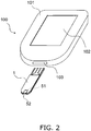
- the above-mentioned sensor 1 is used in the measurement system 100 shown in FIG. 2 .
- the measurement system 100 has the sensor 1 and the measurement device 101.
- the measurement device 101 comprises a display unit 102, a mounting unit 103, a switching circuit 107, a reference voltage source 108, a current/voltage conversion circuit 109, an A/D conversion circuit 110, and a computer 111.
- the measurement device 101 has connectors corresponding to the electrodes of the sensor 1. Connectors 104 to 106 are depicted in FIG. 3 .
- the display unit 102 displays the status of the measurement device 101, measurement results, operational content, and so forth. More specifically, the display unit 102 is constituted by a liquid crystal display panel.
- the senor 1 is removably inserted into the mounting section 103.
- the connectors 104 to 106 are connected to the electrodes 31 to 33 of the sensor 1, respectively by mounting the sensor 1 in the mounting section 103.
- a switching circuit 107 connects the connectors 104 to 106 to a reference voltage source 108, or is connected to a current/voltage conversion circuit 109.
- the reference voltage source 108 applies voltage to the electrodes 31 to 33 via the connectors 104 to 106.
- the current/voltage conversion circuit 109 receives current from the sensor 1 via the connectors 104 to 106, converts this into voltage, and outputs this to an A/D conversion circuit 110.
- the A/D conversion circuit 110 converts the output value (analog value) from the current/voltage conversion circuit 109 into a pulse (digital value).
- the computer 111 has a CPU (central processing unit, as well as a ROM (read only memory), RAM (random access memory), and other such recording media.
- the computer 111 calculates the concentration of the target substance, and controls the operation of the various components in the measurement device 101.
- the concentration calculation function of the computer 111 will be described.
- the storage medium of the computer 111 stores a conversion table used for deciding the concentration of the target substance in the sample, a correction amount table used for deciding the correction amount of this concentration, and so forth.
- the computer 111 refers to this conversion table and calculates the temporary concentration of the target substance on the basis of a pulse from the A/D conversion circuit 110.
- the computer 111 uses the correction amount in the correction amount table to decide the final concentration of the target substance.
- the concentration thus calculated is displayed on the display section 102.
- the computer 111 has functions besides its concentration calculation function, such as controlling the switching of the switching circuit 107, controlling the voltage of the reference voltage source 108, keeping time during concentration measurement and correction amount selection (timer function), outputting display data to the display section 102, and communicating with external devices.
- the various functions of the computer 111 are realized by having the CPU read and execute programs stored in the ROM, etc. (not shown).
- the connectors 104 to 106 are connected to the electrodes 31 to 33, respectively.
- a switch (not shown) inside the mounting section 103 is depressed by the sensor 1.
- the computer 111 determines that the sensor 1 has been mounted, and puts the measurement device 101 in a sample standby state.
- This sample standby state refers to a state in which voltage application between the working electrode 31 and the detecting electrode 33 has been begun by the reference voltage source 108 under the control of the computer 111 and via the connectors 104 and 106, and the current/voltage conversion circuit 109 has begun the measurement of current, but the liquid sample has yet to be supplied for measurement.
- the liquid sample is drawn in through the inlet 52 to the capillary 51 by capillary action.
- Blood, perspiration, urine, and other biological liquid samples, environmental liquid samples, and food liquid samples can be used as the liquid sample.
- the sensor 1 is used as a blood glucose level sensor, the user pricks his finger, palm, arm, or the like and squeezes out a small amount of blood, and this blood is used as a liquid sample for measurement in the sensor 1.
- the enzyme, mediator, and other components in the reagent layer 4 dissolve in the liquid sample. This brings the liquid sample, the enzyme, and the mediator into contact with each other on the electrodes 31 and 32 of the sensor 1.
- Control by the computer 111 causes the switching circuit 107 to connect the connectors 104 and 105 to the reference voltage source 108 and the current/voltage conversion circuit 109. This results in voltage being applied between the working electrode 31 and the counter electrode 32, and the current produced between the working electrode 31 and the counter electrode 32 is transmitted to the current/voltage conversion circuit 109.
- the current that flows to the current/voltage conversion circuit 109 is converted into voltage. This voltage is further converted into a pulse by the A/D conversion circuit 110.
- the computer 111 calculates the concentration of a specific component from this pulse. The value calculated by the computer 111 is displayed on a display section 202. Other information may also be displayed for the user at the same time.
- the user can remove the sensor 1 from the mounting section 103.
- the reference voltage source 108 is designed to provided enough voltage to induce the targeted electrochemical reaction between the two electrodes 31 and 32. This voltage is mainly set according to the chemical reaction and electrodes being used.
- a concentration measurement method is executed that includes:
- the measurement system 100 executes a concentration measurement method that includes:
- the sensor 1 is a sensor for detecting or quantifying a target substance contained in a liquid sample,.
- the target substance is the substrate of the PQQ-dependent or FAD-dependent enzyme.
- the constitution of the sensor 1 comprises an enzyme being PQQ-dependent or FAD-dependent whose substrate is a target substance, electrodes, and a 9,10-phenanthrenequinone-2-sulfonate quinone compound that transmits electrons between the enzyme and the electrodes.
- voltage may be applied to at least one of these pairs of electrodes.
- the sodium 9,10-phenanthrenequinone-2-sulfonate exhibits good solubility as the mediator in a sensor used for a liquid sample in which water is the solvent.
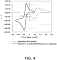
- Potassium ferricyanide and sodium 9,10-phenanthrenequinone-2-sulfonate were each dissolved in an amount of 1 mM in a 100 mM phosphate buffer (pH 7), to prepare a potassium ferricyanide aqueous solution and a sodium 9,10-phenanthrenequinone-2-sulfonate aqueous solution.
- a potentiostat was used for measurement.
- the various electrodes and the potentiostat were types commonly used in electrochemistry. This equipment can be purchased from BAS, for example.
- the cyclic voltammetry involved searching for the potential applied to the working electrode, linearly with respect to time.
- the sweep rate was set to 0.1 V/second.
- a first potential was applied to the working electrode, and the electrode potential was swept to the negative side from the starting potential to a second potential that was more negative.
- sweep was performed in which the electrode potential was flipped back to the positive side from the second potential to the first potential.
- the first and second potentials were 0.7 V and -0.3 V, respectively, in the case of potassium ferricyanide, and were 0.2 V and -0.5 V in the case of sodium 9,10-phenanthrenequinone-2-sulfonate.
- the redox potential for the sodium 9,10-phenanthrenequinone-2-sulfonate is -150 mV and the redox potential for potassium ferricyanide is 225 mV.
- AgCl as a reference electrode was negative.
- Sodium 9,10-phenanthrenequinone-2-sulfonate undergoes a redox reaction quickly and reversibly with a glassy carbon electrode, and at the same time, has a redox potential that is about 400 mV lower than that of potassium ferricyanide. Being able to react quickly and reversibly with the electrode is a favorable characteristic for a mediator used in a sensor that needs to perform measurement in a short time.
- a substance having a lower redox potential is used as a mediator, the effects of measurement interfering substances that are readily oxidizable in a liquid sample, such as acetaminophen or ascorbic acid in the blood, can be reduced, and as a result a sensor capable of more accurate measurement can be obtained.
- the substrate 2 which was 30 mm long, 7 mm wide, and 0.2 mm thick and had polyethylene terephthalate as its main component. This formed the conductive layer 3 in a thickness of 8 nm.
- a non-conductive track with a width of 0.1 mm was formed by laser ablation, which formed the electrodes 31 to 33.
- the electrode 31 was designed to function as a working electrode, the electrode 32 as a counter electrode, and the electrode 33 as a detecting electrode.
- a coating of an aqueous solution containing an enzyme and a mediator was applied in a circular shape with a diameter of 2.2 mm using a microsyringe, thereby forming the reagent layer 4.
- the spacer 5 (0.145 mm thick) having a cut-out with a width of 1.2 mm and a length of 3.4 mm and the cover 6 were affixed in that order to the substrate on which the electrodes had been formed, thus producing the sensor 1 equipped with a cavity having a volume of 0.6 ⁇ L.
- glucose concentration measurement was performed by the measurement system 100, using blood with various glucose concentrations (known) as the liquid sample.
- the results are given in FIG. 5 .
- the sensor having sodium 9,10-phenanthrenequinone-2-sulfonate exhibited equal or better glucose response compared to the sensor having potassium ferricyanide.
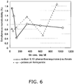
- FIG. 6 shows the results of plotting glucose concentration on the horizontal axis and simultaneous reproducibility on the vertical axis (the quotient of dividing the standard deviation by the average measured value).
- the sensor having the sodium 9,10-phenanthrenequinone-2-sulfonate exhibited equal or better reproducibility as compared to the sensor having the potassium ferricyanide.
- the sensors were used to measure the glucose concentration, using blood to which interfering substances had been added in various concentrations as the liquid sample (glucose concentration of 80 mg/dL). The degree of departure (%) from the true value was found for the average value of six to ten measurements.
- FIG. 7 shows the results when ascorbic acid was used as an interfering substance
- FIG. 8 shows the results when acetaminophen was used as an interfering substance.
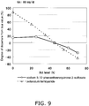
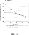
- FIGS. 9 and 10 show the degree of departure from the true value of the measured glucose concentration at hematocrit levels of 0% to 70%.
- the glucose concentration is 80 mg/dL
- the glucose concentration is 336 mg/dL.
- FIG. 11 shows a cyclic voltammogram for the sodium 9,10-phenanthrenequinone-2-sulfonate in FIG. 4 .
- An N-(2-acetamide)-2-aminoethanesulfonic acid (ACES) buffer (pH 7.0) was used as a solvent for a reagent solution used to form a reagent layer.
- the other conditions (such as the types and concentrations of enzyme and mediator in the reagent solution) were the same as in Working Example 1.
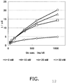
- the response current value corresponding to the glucose concentration was measured for when the buffer section (ACES) concentration was 0, 10, 20, and 30 mM. The results are shown in FIG. 12 .
- the response of the sensor with respect to the glucose concentration improves with the presence of ACES. Also, better response was obtained at a higher ACES concentration.
- the inventors also used a phosphate buffer instead of an ACES buffer to confirm an improvement in the response of a sensor with respect to glucose concentration.
- reagents were prepared by using phosphate buffers with a pH of 6.4, 7.0, and 7.5 as the solvent. These reagents were used to form a reagent layer and to produce three kinds of sensor. The other conditions were the same as in Working Example 1.
- a reagent was prepared using a phosphate buffer with a pH of 6.4 as a solvent, and this reagent was used to form a reagent layer.
- the response current of the sensor with respect to the glucose concentration was compared between when 10 mM trisodium citrate was added to the reagent, and when it was not added.
- the conditions were the same as in Working Example 1.
- adding trisodium citrate improved the linearity of the response current with respect to the glucose concentration.
Claims (3)
- Sensor (1) zum Erfassen oder Quantifizieren einer Zielsubstanz, die in einer flüssigen Probe enthalten ist, Folgendes umfassend:ein PQQ-abhängiges oder FAD-abhängiges Enzym, das die Zielsubstanz oxidiert oder dehydriert;eine Chinon-Verbindung, die Elektronen akzeptiert, welche durch Dehydrierung oder Oxidation der Zielsubstanz durch das Enzym freigesetzt werden; undmindestens ein Paar Elektroden (31, 32, 33),wobei die Chinon-Verbindung ein Chinon und einen Substituenten enthält,wobei der Substituent hydrophil ist, undwobei das Redox-Potenzial der Chinon-Verbindung, gemessen unter Verwendung einer Silber/Silberchlorid (gesättigtes Kaliumchlorid) - Elektrode als eine Referenzelektrode, negativ unter 0V und positiver als das Redox-Potenzial des Coenzyms ist, undwobei das Redox-Potenzial der Chinon-Verbindung, gemessen unter Verwendung einer Silber/Silberchlorid (gesättigtes Kaliumchlorid) - Elektrode als eine Referenzelektrode, negativer als das Oxidationspotenzial von Ascorbinsäure ist,dadurch gekennzeichnet, dass die Chinon-Verbindung ein 9,10-Phenanthrenchinon-2-Sulfonat ist.
- Sensor (1) nach Anspruch 1, wobei das FAD-abhängige Enzym eine Glukose-Dehydrogenase ist.
- Sensor (1) nach einem der Ansprüche 1 oder 2, wobei die flüssige Probe Blut einschließt.
Applications Claiming Priority (3)
| Application Number | Priority Date | Filing Date | Title |
|---|---|---|---|
| JP2009201116 | 2009-08-31 | ||
| PCT/JP2010/005341 WO2011024487A1 (ja) | 2009-08-31 | 2010-08-30 | センサ及び濃度測定方法 |
| EP10811541.1A EP2474825B1 (de) | 2009-08-31 | 2010-08-30 | Sensor und konzentrationsmessverfahren |
Related Parent Applications (2)
| Application Number | Title | Priority Date | Filing Date |
|---|---|---|---|
| EP10811541.1A Division EP2474825B1 (de) | 2009-08-31 | 2010-08-30 | Sensor und konzentrationsmessverfahren |
| EP10811541.1A Division-Into EP2474825B1 (de) | 2009-08-31 | 2010-08-30 | Sensor und konzentrationsmessverfahren |
Publications (3)
| Publication Number | Publication Date |
|---|---|
| EP3343213A2 EP3343213A2 (de) | 2018-07-04 |
| EP3343213A3 EP3343213A3 (de) | 2018-08-29 |
| EP3343213B1 true EP3343213B1 (de) | 2019-10-23 |
Family
ID=43627602
Family Applications (2)
| Application Number | Title | Priority Date | Filing Date |
|---|---|---|---|
| EP18151485.2A Active EP3343213B1 (de) | 2009-08-31 | 2010-08-30 | Sensor |
| EP10811541.1A Active EP2474825B1 (de) | 2009-08-31 | 2010-08-30 | Sensor und konzentrationsmessverfahren |
Family Applications After (1)
| Application Number | Title | Priority Date | Filing Date |
|---|---|---|---|
| EP10811541.1A Active EP2474825B1 (de) | 2009-08-31 | 2010-08-30 | Sensor und konzentrationsmessverfahren |
Country Status (5)
| Country | Link |
|---|---|
| US (3) | US9212380B2 (de) |
| EP (2) | EP3343213B1 (de) |
| JP (5) | JP5352670B2 (de) |
| CN (1) | CN102498391B (de) |
| WO (1) | WO2011024487A1 (de) |
Families Citing this family (14)
| Publication number | Priority date | Publication date | Assignee | Title |
|---|---|---|---|---|
| WO2011024487A1 (ja) * | 2009-08-31 | 2011-03-03 | パナソニック株式会社 | センサ及び濃度測定方法 |
| WO2012042903A1 (ja) | 2010-09-30 | 2012-04-05 | パナソニック株式会社 | 試薬組成物、センサ、センサシステム及びセンサの製造方法 |
| JP5684767B2 (ja) | 2011-09-26 | 2015-03-18 | アークレイ株式会社 | 乳酸センサ |
| MX2014003415A (es) | 2011-09-28 | 2014-04-10 | Hoffmann La Roche | Mediadores azo. |
| IN2014CN03415A (de) * | 2011-11-18 | 2015-10-09 | Murata Manufacturing Co | |
| JP6035278B2 (ja) * | 2014-05-01 | 2016-11-30 | 学校法人 日本歯科大学 | 咀嚼能力測定装置及び咀嚼能力測定方法 |
| CN106033070B (zh) * | 2015-03-16 | 2019-05-14 | 恩莱生医科技股份有限公司 | 农药检测装置 |
| JP6610025B2 (ja) * | 2015-06-22 | 2019-11-27 | 株式会社村田製作所 | バイオセンサ |
| US10011549B2 (en) * | 2015-07-06 | 2018-07-03 | Robert Bosch Gmbh | Electrochemically active agents for pH modulation in biological buffers |
| JP6823436B2 (ja) * | 2015-12-07 | 2021-02-03 | アークレイ株式会社 | 目的成分の測定方法および目的成分の測定装置 |
| KR102044061B1 (ko) * | 2016-12-21 | 2019-11-12 | 주식회사 유엑스엔 | 연속 혈당 측정장치, 상기 장치를 포함한 연속 혈당 측정시스템 및 연속 혈당 측정방법 |
| CN109204528B (zh) * | 2017-06-30 | 2021-05-14 | 比亚迪股份有限公司 | 车辆及其车身结构 |
| US10040948B1 (en) | 2017-11-21 | 2018-08-07 | Uxn Co., Ltd. | Method of making a colloid and nanoporous layer |
| JP7139802B2 (ja) | 2018-09-10 | 2022-09-21 | マツダ株式会社 | 車両の後部車体構造 |
Family Cites Families (26)
| Publication number | Priority date | Publication date | Assignee | Title |
|---|---|---|---|---|
| EP0136362B1 (de) * | 1983-03-11 | 1990-12-19 | Matsushita Electric Industrial Co., Ltd. | Biosensor |
| JP2517153B2 (ja) * | 1989-09-21 | 1996-07-24 | 松下電器産業株式会社 | バイオセンサおよびその製造法 |
| CA2069946C (en) * | 1989-12-15 | 1999-01-26 | Klaus H. Pollmann | Redox mediator reagent and biosensor |
| CN1110700A (zh) | 1994-04-28 | 1995-10-25 | 王玉才 | 多元复合防沉粉 |
| JPH09297121A (ja) | 1996-03-07 | 1997-11-18 | Matsushita Electric Ind Co Ltd | コレステロールセンサ |
| US6214612B1 (en) | 1996-03-07 | 2001-04-10 | Matsushita Electric Industrial Co., Ltd. | Cholesterol sensor containing electrodes, cholesterol dehydrogenase, nicotinamide adenine dinucleotide and oxidized electron mediator |
| US5866353A (en) * | 1996-12-09 | 1999-02-02 | Bayer Corporation | Electro chemical biosensor containing diazacyanine mediator for co-enzyme regeneration |
| JP3297630B2 (ja) * | 1997-07-28 | 2002-07-02 | 松下電器産業株式会社 | バイオセンサ |
| CO5040209A1 (es) | 1997-10-16 | 2001-05-29 | Abbott Lab | Electrodos biosensores mediadores de la regeneracion de cofactores |
| US6736957B1 (en) | 1997-10-16 | 2004-05-18 | Abbott Laboratories | Biosensor electrode mediators for regeneration of cofactors and process for using |
| JP3267936B2 (ja) | 1998-08-26 | 2002-03-25 | 松下電器産業株式会社 | バイオセンサ |
| JP3694424B2 (ja) | 1998-09-29 | 2005-09-14 | 松下電器産業株式会社 | グルコースセンサ |
| JP4364331B2 (ja) * | 1998-12-24 | 2009-11-18 | 旭化成株式会社 | 酵素を用いる分析方法 |
| JP4197085B2 (ja) | 2000-04-25 | 2008-12-17 | パナソニック株式会社 | バイオセンサ |
| CN100363739C (zh) | 1999-11-15 | 2008-01-23 | 松下电器产业株式会社 | 生物传感器、薄膜电极形成方法、定量装置及定量方法 |
| US6726818B2 (en) * | 2000-07-21 | 2004-04-27 | I-Sens, Inc. | Biosensors with porous chromatographic membranes |
| US6676816B2 (en) * | 2001-05-11 | 2004-01-13 | Therasense, Inc. | Transition metal complexes with (pyridyl)imidazole ligands and sensors using said complexes |
| US6863800B2 (en) * | 2002-02-01 | 2005-03-08 | Abbott Laboratories | Electrochemical biosensor strip for analysis of liquid samples |
| US7267837B2 (en) * | 2003-01-16 | 2007-09-11 | Arun Kumar | Enzyme electrode and process for preparation thereof |
| DE10303265A1 (de) | 2003-01-28 | 2004-07-29 | Roche Diagnostics Gmbh | Fluorimetrische Bestimmung von Analyten durch ein intramolekulares Quencher-Fluorophor-Konjugat |
| CA2543957C (en) * | 2003-10-31 | 2013-01-22 | Lifescan Scotland Limited | Method of reducing the effect of direct interference current in an electrochemical test strip |
| CA2658036A1 (en) | 2006-04-19 | 2007-11-01 | Panasonic Corporation | Biosensor |
| JP2008071584A (ja) * | 2006-09-13 | 2008-03-27 | Toyota Motor Corp | 電子伝達メディエータ修飾酵素電極及びこれを備える生物燃料電池 |
| EP1964927A1 (de) * | 2007-02-27 | 2008-09-03 | F. Hoffmann-La Roche AG | Chinone als Mediatoren für photometrische Teste |
| JP2010237145A (ja) | 2009-03-31 | 2010-10-21 | Cci Corp | バイオセンサ |
| WO2011024487A1 (ja) * | 2009-08-31 | 2011-03-03 | パナソニック株式会社 | センサ及び濃度測定方法 |
-
2010
- 2010-08-30 WO PCT/JP2010/005341 patent/WO2011024487A1/ja active Application Filing
- 2010-08-30 JP JP2011528661A patent/JP5352670B2/ja active Active
- 2010-08-30 CN CN201080034694.0A patent/CN102498391B/zh active Active
- 2010-08-30 US US13/392,630 patent/US9212380B2/en active Active
- 2010-08-30 EP EP18151485.2A patent/EP3343213B1/de active Active
- 2010-08-30 EP EP10811541.1A patent/EP2474825B1/de active Active
-
2013
- 2013-08-26 JP JP2013174473A patent/JP5686871B2/ja active Active
-
2015
- 2015-01-20 JP JP2015008584A patent/JP5976853B2/ja active Active
- 2015-11-10 US US14/936,964 patent/US10761044B2/en active Active
-
2016
- 2016-07-20 JP JP2016142368A patent/JP6181823B2/ja active Active
-
2017
- 2017-07-20 JP JP2017140583A patent/JP6338748B2/ja active Active
-
2020
- 2020-07-23 US US16/936,638 patent/US11639912B2/en active Active
Non-Patent Citations (1)
| Title |
|---|
| None * |
Also Published As
| Publication number | Publication date |
|---|---|
| JP2016180768A (ja) | 2016-10-13 |
| EP3343213A2 (de) | 2018-07-04 |
| JP5976853B2 (ja) | 2016-08-24 |
| JP6338748B2 (ja) | 2018-06-06 |
| US9212380B2 (en) | 2015-12-15 |
| US11639912B2 (en) | 2023-05-02 |
| JP2013235017A (ja) | 2013-11-21 |
| JP2015072288A (ja) | 2015-04-16 |
| US20200348255A1 (en) | 2020-11-05 |
| CN102498391B (zh) | 2014-03-19 |
| JP5352670B2 (ja) | 2013-11-27 |
| EP3343213A3 (de) | 2018-08-29 |
| EP2474825A1 (de) | 2012-07-11 |
| JPWO2011024487A1 (ja) | 2013-01-24 |
| US20160061764A1 (en) | 2016-03-03 |
| EP2474825A4 (de) | 2014-08-13 |
| US10761044B2 (en) | 2020-09-01 |
| WO2011024487A1 (ja) | 2011-03-03 |
| JP6181823B2 (ja) | 2017-08-16 |
| US20120152763A1 (en) | 2012-06-21 |
| EP2474825B1 (de) | 2018-07-04 |
| CN102498391A (zh) | 2012-06-13 |
| JP2017194484A (ja) | 2017-10-26 |
| JP5686871B2 (ja) | 2015-03-18 |
Similar Documents
| Publication | Publication Date | Title |
|---|---|---|
| EP3343213B1 (de) | Sensor | |
| EP1398386B1 (de) | Mediator-stabilisierende Verbindung und Methoden zur Verwendung zur Detektion elektrochemischer Analyte | |
| JP6450426B2 (ja) | センサ及びセンサシステム | |
| JP4018082B2 (ja) | 電気化学バイオセンサ | |
| US9938556B2 (en) | Reagent composition for biosensor and biosensor having the same | |
| US8500990B2 (en) | Electrochemical biosensors based on NAD(P)-dependent dehydrogenase enzymes | |
| EP3242129B1 (de) | Elektrochemischer biosensor | |
| JP2006349412A (ja) | クレアチニンバイオセンサ | |
| WO1995021934A1 (en) | Hexacyanoferrate modified electrodes | |
| WO2013073072A1 (ja) | ヘマトクリット値の測定方法およびこの測定方法を用いた定量分析方法並びにセンサチップ |
Legal Events
| Date | Code | Title | Description |
|---|---|---|---|
| PUAI | Public reference made under article 153(3) epc to a published international application that has entered the european phase |
Free format text: ORIGINAL CODE: 0009012 |
|
| STAA | Information on the status of an ep patent application or granted ep patent |
Free format text: STATUS: REQUEST FOR EXAMINATION WAS MADE |
|
| 17P | Request for examination filed |
Effective date: 20180112 |
|
| AC | Divisional application: reference to earlier application |
Ref document number: 2474825 Country of ref document: EP Kind code of ref document: P |
|
| AK | Designated contracting states |
Kind code of ref document: A2 Designated state(s): AL AT BE BG CH CY CZ DE DK EE ES FI FR GB GR HR HU IE IS IT LI LT LU LV MC MK MT NL NO PL PT RO SE SI SK SM TR |
|
| PUAL | Search report despatched |
Free format text: ORIGINAL CODE: 0009013 |
|
| RAP1 | Party data changed (applicant data changed or rights of an application transferred) |
Owner name: PHC HOLDINGS CORPORATION |
|
| AK | Designated contracting states |
Kind code of ref document: A3 Designated state(s): AL AT BE BG CH CY CZ DE DK EE ES FI FR GB GR HR HU IE IS IT LI LT LU LV MC MK MT NL NO PL PT RO SE SI SK SM TR |
|
| RIC1 | Information provided on ipc code assigned before grant |
Ipc: C12Q 1/32 20060101ALI20180724BHEP Ipc: G01N 21/84 20060101ALI20180724BHEP Ipc: C12Q 1/00 20060101ALI20180724BHEP Ipc: G01N 21/75 20060101ALI20180724BHEP Ipc: G01N 27/327 20060101AFI20180724BHEP Ipc: G01N 21/27 20060101ALI20180724BHEP Ipc: G01N 27/416 20060101ALI20180724BHEP |
|
| GRAP | Despatch of communication of intention to grant a patent |
Free format text: ORIGINAL CODE: EPIDOSNIGR1 |
|
| INTG | Intention to grant announced |
Effective date: 20190617 |
|
| RIN1 | Information on inventor provided before grant (corrected) |
Inventor name: TAKAHARA, YOSHIFUMI Inventor name: NAKAMINAMI, TAKAHIRO Inventor name: IKEDA, SHIN |
|
| STAA | Information on the status of an ep patent application or granted ep patent |
Free format text: STATUS: GRANT OF PATENT IS INTENDED |
|
| GRAS | Grant fee paid |
Free format text: ORIGINAL CODE: EPIDOSNIGR3 |
|
| GRAA | (expected) grant |
Free format text: ORIGINAL CODE: 0009210 |
|
| STAA | Information on the status of an ep patent application or granted ep patent |
Free format text: STATUS: THE PATENT HAS BEEN GRANTED |
|
| AC | Divisional application: reference to earlier application |
Ref document number: 2474825 Country of ref document: EP Kind code of ref document: P |
|
| AK | Designated contracting states |
Kind code of ref document: B1 Designated state(s): AL AT BE BG CH CY CZ DE DK EE ES FI FR GB GR HR HU IE IS IT LI LT LU LV MC MK MT NL NO PL PT RO SE SI SK SM TR |
|
| REG | Reference to a national code |
Ref country code: GB Ref legal event code: FG4D |
|
| REG | Reference to a national code |
Ref country code: CH Ref legal event code: EP |
|
| REG | Reference to a national code |
Ref country code: IE Ref legal event code: FG4D |
|
| REG | Reference to a national code |
Ref country code: DE Ref legal event code: R096 Ref document number: 602010061706 Country of ref document: DE |
|
| REG | Reference to a national code |
Ref country code: AT Ref legal event code: REF Ref document number: 1194211 Country of ref document: AT Kind code of ref document: T Effective date: 20191115 |
|
| REG | Reference to a national code |
Ref country code: NL Ref legal event code: MP Effective date: 20191023 |
|
| REG | Reference to a national code |
Ref country code: LT Ref legal event code: MG4D |
|
| PG25 | Lapsed in a contracting state [announced via postgrant information from national office to epo] |
Ref country code: NL Free format text: LAPSE BECAUSE OF FAILURE TO SUBMIT A TRANSLATION OF THE DESCRIPTION OR TO PAY THE FEE WITHIN THE PRESCRIBED TIME-LIMIT Effective date: 20191023 Ref country code: GR Free format text: LAPSE BECAUSE OF FAILURE TO SUBMIT A TRANSLATION OF THE DESCRIPTION OR TO PAY THE FEE WITHIN THE PRESCRIBED TIME-LIMIT Effective date: 20200124 Ref country code: LT Free format text: LAPSE BECAUSE OF FAILURE TO SUBMIT A TRANSLATION OF THE DESCRIPTION OR TO PAY THE FEE WITHIN THE PRESCRIBED TIME-LIMIT Effective date: 20191023 Ref country code: PT Free format text: LAPSE BECAUSE OF FAILURE TO SUBMIT A TRANSLATION OF THE DESCRIPTION OR TO PAY THE FEE WITHIN THE PRESCRIBED TIME-LIMIT Effective date: 20200224 Ref country code: FI Free format text: LAPSE BECAUSE OF FAILURE TO SUBMIT A TRANSLATION OF THE DESCRIPTION OR TO PAY THE FEE WITHIN THE PRESCRIBED TIME-LIMIT Effective date: 20191023 Ref country code: BG Free format text: LAPSE BECAUSE OF FAILURE TO SUBMIT A TRANSLATION OF THE DESCRIPTION OR TO PAY THE FEE WITHIN THE PRESCRIBED TIME-LIMIT Effective date: 20200123 Ref country code: SE Free format text: LAPSE BECAUSE OF FAILURE TO SUBMIT A TRANSLATION OF THE DESCRIPTION OR TO PAY THE FEE WITHIN THE PRESCRIBED TIME-LIMIT Effective date: 20191023 Ref country code: LV Free format text: LAPSE BECAUSE OF FAILURE TO SUBMIT A TRANSLATION OF THE DESCRIPTION OR TO PAY THE FEE WITHIN THE PRESCRIBED TIME-LIMIT Effective date: 20191023 Ref country code: PL Free format text: LAPSE BECAUSE OF FAILURE TO SUBMIT A TRANSLATION OF THE DESCRIPTION OR TO PAY THE FEE WITHIN THE PRESCRIBED TIME-LIMIT Effective date: 20191023 Ref country code: NO Free format text: LAPSE BECAUSE OF FAILURE TO SUBMIT A TRANSLATION OF THE DESCRIPTION OR TO PAY THE FEE WITHIN THE PRESCRIBED TIME-LIMIT Effective date: 20200123 |
|
| PG25 | Lapsed in a contracting state [announced via postgrant information from national office to epo] |
Ref country code: IS Free format text: LAPSE BECAUSE OF FAILURE TO SUBMIT A TRANSLATION OF THE DESCRIPTION OR TO PAY THE FEE WITHIN THE PRESCRIBED TIME-LIMIT Effective date: 20200224 Ref country code: HR Free format text: LAPSE BECAUSE OF FAILURE TO SUBMIT A TRANSLATION OF THE DESCRIPTION OR TO PAY THE FEE WITHIN THE PRESCRIBED TIME-LIMIT Effective date: 20191023 |
|
| PG25 | Lapsed in a contracting state [announced via postgrant information from national office to epo] |
Ref country code: AL Free format text: LAPSE BECAUSE OF FAILURE TO SUBMIT A TRANSLATION OF THE DESCRIPTION OR TO PAY THE FEE WITHIN THE PRESCRIBED TIME-LIMIT Effective date: 20191023 |
|
| REG | Reference to a national code |
Ref country code: DE Ref legal event code: R097 Ref document number: 602010061706 Country of ref document: DE |
|
| PG2D | Information on lapse in contracting state deleted |
Ref country code: IS |
|
| PG25 | Lapsed in a contracting state [announced via postgrant information from national office to epo] |
Ref country code: RO Free format text: LAPSE BECAUSE OF FAILURE TO SUBMIT A TRANSLATION OF THE DESCRIPTION OR TO PAY THE FEE WITHIN THE PRESCRIBED TIME-LIMIT Effective date: 20191023 Ref country code: CZ Free format text: LAPSE BECAUSE OF FAILURE TO SUBMIT A TRANSLATION OF THE DESCRIPTION OR TO PAY THE FEE WITHIN THE PRESCRIBED TIME-LIMIT Effective date: 20191023 Ref country code: ES Free format text: LAPSE BECAUSE OF FAILURE TO SUBMIT A TRANSLATION OF THE DESCRIPTION OR TO PAY THE FEE WITHIN THE PRESCRIBED TIME-LIMIT Effective date: 20191023 Ref country code: EE Free format text: LAPSE BECAUSE OF FAILURE TO SUBMIT A TRANSLATION OF THE DESCRIPTION OR TO PAY THE FEE WITHIN THE PRESCRIBED TIME-LIMIT Effective date: 20191023 Ref country code: DK Free format text: LAPSE BECAUSE OF FAILURE TO SUBMIT A TRANSLATION OF THE DESCRIPTION OR TO PAY THE FEE WITHIN THE PRESCRIBED TIME-LIMIT Effective date: 20191023 Ref country code: IS Free format text: LAPSE BECAUSE OF FAILURE TO SUBMIT A TRANSLATION OF THE DESCRIPTION OR TO PAY THE FEE WITHIN THE PRESCRIBED TIME-LIMIT Effective date: 20200223 |
|
| REG | Reference to a national code |
Ref country code: AT Ref legal event code: MK05 Ref document number: 1194211 Country of ref document: AT Kind code of ref document: T Effective date: 20191023 |
|
| PLBE | No opposition filed within time limit |
Free format text: ORIGINAL CODE: 0009261 |
|
| STAA | Information on the status of an ep patent application or granted ep patent |
Free format text: STATUS: NO OPPOSITION FILED WITHIN TIME LIMIT |
|
| PG25 | Lapsed in a contracting state [announced via postgrant information from national office to epo] |
Ref country code: SM Free format text: LAPSE BECAUSE OF FAILURE TO SUBMIT A TRANSLATION OF THE DESCRIPTION OR TO PAY THE FEE WITHIN THE PRESCRIBED TIME-LIMIT Effective date: 20191023 Ref country code: SK Free format text: LAPSE BECAUSE OF FAILURE TO SUBMIT A TRANSLATION OF THE DESCRIPTION OR TO PAY THE FEE WITHIN THE PRESCRIBED TIME-LIMIT Effective date: 20191023 Ref country code: IT Free format text: LAPSE BECAUSE OF FAILURE TO SUBMIT A TRANSLATION OF THE DESCRIPTION OR TO PAY THE FEE WITHIN THE PRESCRIBED TIME-LIMIT Effective date: 20191023 |
|
| 26N | No opposition filed |
Effective date: 20200724 |
|
| PG25 | Lapsed in a contracting state [announced via postgrant information from national office to epo] |
Ref country code: SI Free format text: LAPSE BECAUSE OF FAILURE TO SUBMIT A TRANSLATION OF THE DESCRIPTION OR TO PAY THE FEE WITHIN THE PRESCRIBED TIME-LIMIT Effective date: 20191023 Ref country code: AT Free format text: LAPSE BECAUSE OF FAILURE TO SUBMIT A TRANSLATION OF THE DESCRIPTION OR TO PAY THE FEE WITHIN THE PRESCRIBED TIME-LIMIT Effective date: 20191023 |
|
| PG25 | Lapsed in a contracting state [announced via postgrant information from national office to epo] |
Ref country code: MC Free format text: LAPSE BECAUSE OF FAILURE TO SUBMIT A TRANSLATION OF THE DESCRIPTION OR TO PAY THE FEE WITHIN THE PRESCRIBED TIME-LIMIT Effective date: 20191023 |
|
| REG | Reference to a national code |
Ref country code: CH Ref legal event code: PL |
|
| GBPC | Gb: european patent ceased through non-payment of renewal fee |
Effective date: 20200830 |
|
| PG25 | Lapsed in a contracting state [announced via postgrant information from national office to epo] |
Ref country code: LI Free format text: LAPSE BECAUSE OF NON-PAYMENT OF DUE FEES Effective date: 20200831 Ref country code: LU Free format text: LAPSE BECAUSE OF NON-PAYMENT OF DUE FEES Effective date: 20200830 Ref country code: CH Free format text: LAPSE BECAUSE OF NON-PAYMENT OF DUE FEES Effective date: 20200831 |
|
| REG | Reference to a national code |
Ref country code: BE Ref legal event code: MM Effective date: 20200831 |
|
| PG25 | Lapsed in a contracting state [announced via postgrant information from national office to epo] |
Ref country code: FR Free format text: LAPSE BECAUSE OF NON-PAYMENT OF DUE FEES Effective date: 20200831 |
|
| PG25 | Lapsed in a contracting state [announced via postgrant information from national office to epo] |
Ref country code: BE Free format text: LAPSE BECAUSE OF NON-PAYMENT OF DUE FEES Effective date: 20200831 Ref country code: GB Free format text: LAPSE BECAUSE OF NON-PAYMENT OF DUE FEES Effective date: 20200830 Ref country code: IE Free format text: LAPSE BECAUSE OF NON-PAYMENT OF DUE FEES Effective date: 20200830 |
|
| PG25 | Lapsed in a contracting state [announced via postgrant information from national office to epo] |
Ref country code: TR Free format text: LAPSE BECAUSE OF FAILURE TO SUBMIT A TRANSLATION OF THE DESCRIPTION OR TO PAY THE FEE WITHIN THE PRESCRIBED TIME-LIMIT Effective date: 20191023 Ref country code: MT Free format text: LAPSE BECAUSE OF FAILURE TO SUBMIT A TRANSLATION OF THE DESCRIPTION OR TO PAY THE FEE WITHIN THE PRESCRIBED TIME-LIMIT Effective date: 20191023 Ref country code: CY Free format text: LAPSE BECAUSE OF FAILURE TO SUBMIT A TRANSLATION OF THE DESCRIPTION OR TO PAY THE FEE WITHIN THE PRESCRIBED TIME-LIMIT Effective date: 20191023 |
|
| PG25 | Lapsed in a contracting state [announced via postgrant information from national office to epo] |
Ref country code: MK Free format text: LAPSE BECAUSE OF FAILURE TO SUBMIT A TRANSLATION OF THE DESCRIPTION OR TO PAY THE FEE WITHIN THE PRESCRIBED TIME-LIMIT Effective date: 20191023 |
|
| GRAP | Despatch of communication of intention to grant a patent |
Free format text: ORIGINAL CODE: EPIDOSNIGR1 |
|
| PGFP | Annual fee paid to national office [announced via postgrant information from national office to epo] |
Ref country code: DE Payment date: 20230829 Year of fee payment: 14 |