EP3340840B1 - Anziehhilfe für stützstrümpfe - Google Patents
Anziehhilfe für stützstrümpfe Download PDFInfo
- Publication number
- EP3340840B1 EP3340840B1 EP16767130.4A EP16767130A EP3340840B1 EP 3340840 B1 EP3340840 B1 EP 3340840B1 EP 16767130 A EP16767130 A EP 16767130A EP 3340840 B1 EP3340840 B1 EP 3340840B1
- Authority
- EP
- European Patent Office
- Prior art keywords
- carrier element
- aid
- putting
- motor
- drive
- Prior art date
- Legal status (The legal status is an assumption and is not a legal conclusion. Google has not performed a legal analysis and makes no representation as to the accuracy of the status listed.)
- Active
Links
Images



Classifications
-
- A—HUMAN NECESSITIES
- A47—FURNITURE; DOMESTIC ARTICLES OR APPLIANCES; COFFEE MILLS; SPICE MILLS; SUCTION CLEANERS IN GENERAL
- A47G—HOUSEHOLD OR TABLE EQUIPMENT
- A47G25/00—Household implements used in connection with wearing apparel; Dress, hat or umbrella holders
- A47G25/90—Devices for domestic use for assisting in putting-on or pulling-off clothing, e.g. stockings or trousers
- A47G25/905—Devices for domestic use for assisting in putting-on or pulling-off clothing, e.g. stockings or trousers for stockings
-
- A—HUMAN NECESSITIES
- A47—FURNITURE; DOMESTIC ARTICLES OR APPLIANCES; COFFEE MILLS; SPICE MILLS; SUCTION CLEANERS IN GENERAL
- A47G—HOUSEHOLD OR TABLE EQUIPMENT
- A47G25/00—Household implements used in connection with wearing apparel; Dress, hat or umbrella holders
- A47G25/90—Devices for domestic use for assisting in putting-on or pulling-off clothing, e.g. stockings or trousers
Definitions
- the invention relates to the field of orthopedic aids, in particular orthopedic stockings and in particular devices which facilitate the handling thereof.
- Orthopedic stockings also called support or compression stockings, are used, for example, in the aftermath of a thrombosis, for the treatment of varicose veins and "open legs", as well as support in sports and in activities that involve long standing.
- Rubber gloves are widespread, which have an increased coefficient of friction due to their surface properties, which makes gripping and pulling the support stocking easier.
- the effort itself, which to refer to Taking off the support stocking is required, however, even when using such rubber gloves, it must continue to be applied over the hands to an undiminished extent.
- Support stump pretensioning devices are more suitable in this respect, by means of which a part of the support stocking can be clamped on, so that the body part can be pushed into it more easily. Such devices are usually bulky and cannot be used to remove the stocking. In addition, a not inconsiderable amount of time is required to pull the support stocking onto the pretensioning device.
- Another type of donning aid uses spreading aids which can be moved along the body part. These include rings, on which the stockings are rolled up in a first step and rolled off on the body part in a second step.
- the documents GB 850165-A , DE 8906458 UI and DE 102004032555 A1 describe tightening aids of this type, whereby, in addition to the underlying concept, the rolling behavior of the ring and the problem of its shape being too rigid are dealt with primarily.
- US 636636 also a puller with which the stocking can be wound onto the deformable ring before being put on
- WO 2012/032459 A1 shows an auxiliary device for socks, wherein the auxiliary device comprises a ring, a carrier and an expanding tool. Ring and carrier are coordinated so that a sock attached to the ring can be rolled up by moving along the carrier. With the expanding tool, the opening of a rolled-up sock can be enlarged so that a limb can be better inserted into the opening and the sock can be put on more easily.
- WO 2012/032459 A1 shows various embodiments of the expansion tool, including one in which the force required for expansion is provided by a motor.
- DE 69320493 T2 shows a device with which the opening of a stocking can be widened by the device having a so-called organ made of elements with joints.
- the organ can assume a collapsed starting position in which it can be pushed into the stocking and an unfolded final position in which it widens the stocking.
- the energy required for the transition from the starting position to the end position is applied by an electric motor.
- This electric motor together with a rod to which the organ is attached, can produce a pulling movement for covering the stocking.
- US 8356735 B1 teaches a carrier to which a wound stocking can be attached and which can be placed in a device with a motor.
- the carrier, device and motor are designed such that a leg can be positioned in such a way that the stocking is attracted by a movement of the carrier fed by the motor along the device.
- the claimed invention relates to a device which serves both for putting on and taking off support stockings
- the device is referred to below as a putting-on aid.
- this expression has no restrictive meaning and in particular does not exclude the removal of a support stocking and any preparatory steps, such as, for example, rolling the support stocking onto a donning aid or on parts thereof or positioning the donning aid or parts thereof.
- One embodiment of the donning aid has a carrier element, the surface of which comes into contact with the support stocking, and at least one motor.
- the at least one motor sets parts of the carrier element, for example parts of this surface, in motion, wherein this movement can at least support a rolling off and rolling up of the support stocking after the support stocking and support element have been brought into contact with one another in a certain relative position.
- the tightening aid has exactly one motor which is set up to set parts of the carrier element and / or its surface in motion.
- the tightening aid it is also possible for the tightening aid to have two, three, four or more motors, the different motors being able to be of the same type or, for example, differing in their mode of operation, arrangement and / or characteristic properties (for example generated torque, size, etc.) can.
- the at least one motor is part of the carrier element, for example in that it is located in an interior space defined by the surface of the carrier element.
- the motor can be the drive motor described in detail below.
- the drive unit can have at least one motor, which is located in a component of the tightening aid that is different from the carrier element.
- the tightening aid has a guide rail.
- the motor can be integrated into the guide rail and set the carrier element in motion, for example using a guide jaw.
- the movement generated in this way can in particular have a movement along the body part to which the support stocking is attached or from which the support stocking should be removed.
- Motor, guide rail and / or guide jaws can be set up in such a way that the motor induces a self-rotation of the carrier element or that the motor, guide rail and / or guide jaws at least do not prevent such self-rotation.
- the motor can be the guide motor described in detail below.
- this position can be provided, for example, by hooking the part of the support stocking defining the opening to the support element, so that this part of the support stocking and the support element are connected firmly but releasably are.
- the surface of the support element can be such that the coefficient of friction of the support stocking on this surface is so high that sliding of the support stocking on it is prevented.
- the surface can have knobs, hooks or clamps.
- it can be made of a material that has a high coefficient of friction.
- the carrier element is also designed such that it is able to at least partially enclose a body part, for example a leg, an arm or parts of the leg or arm.
- the carrier element can additionally have a mechanism by which the carrier element changes from a state in which it surrounds the body part to a state in which it not completely encloses the body part, can be brought.
- a mechanism includes a closing and opening mechanism, for example based on a sliding or plug connection or a bayonet lock.
- Such a mechanism also includes means for enlarging the opening created after the opening of the carrier element, for example in that the carrier element can be deformed in the open state or in that parts thereof can be angled via a joint.
- the carrier element can also be designed such that a closing / opening mechanism can be dispensed with.
- the carrier element can be positioned on or removed from the body part by moving the carrier element along the body part in a state in which it at least partially encloses the body part as in operation.
- the carrier element can be designed in such a way that it is deformable to the extent that simple application of the carrier element to the body part or simple placement is made possible.
- This deformability can be achieved, for example, by the support element having elastic elements or by having mechanical elements by means of which the dimensions of the support element can be changed.
- These elastic elements include an element which is designed to generate an internal stress in the carrier element.
- the internal stress leads to a contraction of the carrier element, which in particular causes a reduction in the area in which the body part is in operation and which is defined by the shape of the carrier element. It works in operation Body part counteracts this contraction, whereby the carrier element exerts a pressure dependent on the elastic element on the body part.
- Springs and elastic bands are examples of such elastic elements.
- carrier elements which are able to completely enclose a body part can have such an elastic element.
- the force generated by the at least one motor and transmitted via the movement of the support element and / or via the surface of the support element is preferably sufficient to ensure that the support stocking is rolled up and down without the user providing support.
- the power transmission between the at least one motor and the parts of the carrier element or between the at least one motor and the surface of the carrier element takes place in particular via at least one transmission.
- Each unit consisting of a motor and at least one transmission generates a torque of at least 5 Nm, for example at least 10 Nm, preferably at least 50 Nm or at least 100 Nm.
- the total torque generated by the carrier element can be increased further, or the requirement for each motor / gear unit can be reduced with respect to the torque generated.
- the total torque generated by the carrier element is at least 10 Nm, in particular at least 50 Nm or at least 100 Nm or at least 200 Nm.
- the force generated by the at least one motor optionally translated by at least one gear and transmitted via the movement of the support element and / or via the surface of the support element, is sufficient to unroll and roll up support stockings up to and with compression class 4, but at least up to and with compression class 3 or at least up to and with compression class 2, without ensuring user support.
- the carrier element can carry out the two opposite movements required for unrolling and unrolling, there is also the possibility of preventing or slowing down the unwinding caused by the stresses occurring in the support stocking by the motor.
- the donning aid is used to accomplish or facilitate or support the unrolling and rolling up of the support stocking directly on a body part, that is to say the donning aid can be used directly for putting on and taking off the support stocking.
- the carrier element at least partially surrounds the body part and the carrier element proceeds along the body part. This progression along the body part is coordinated with the movement for unrolling and rolling up in such a way that the support stocking ideally lies on the body part without the occurrence of wrinkles and without undue stress on the support stocking along the direction of advancement of the support element.
- the support element at least partially encloses a body part and progresses along this body part during the unrolling and rolling up of the support stocking, this progress being designed in such a way that in combination with the unrolling and unrolling of the support stocking, the same takes place.
- the rolling / rolling up and the advancement of the carrier element along the body part can be brought about by the same movement of the carrier element or by parts thereof and thus by the same at least one motor.
- the donning aid may have motors which perform different functions.
- one or more motors of a first type can cause the carrier element to rotate itself, while one or more motors of a second type support or cause a displacement of the carrier element along the body part.
- motors of a third type which increase the user-friendliness or the comfort of the tightening device. The latter may include automatically adjusting the dimensions of the donning aid or parts thereof.
- the carrier element has the shape of a torus.
- the carrier element can deviate somewhat from this shape, since components of the carrier element, such as the drive unit described below or the adjustment mechanism described below, can have a straight shape.
- the carrier element can have the shape of a rotation torus.
- the shape of a rotation torus is created, for example, by rotating a circle around an axis of rotation, the axis of rotation preferably being perpendicular to the normal to the surface defined by the circle.
- a rotation torus defined in this way has a circular line which is given by the path of the center of the rotating circle. The circular line thus runs centrally within the volume of the rotation torus.
- a rotation torus defined in this way also has a large radius, which corresponds to the radius of the circle defined by the circular line, and a small radius, which corresponds to the radius of the rotating circle.
- the large radius In order for a rotation torus to be created in the sense of the invention, the large radius must be larger than the small radius.
- the carrier element also has at least one drive unit and at least one propulsion unit.
- Each of the at least one propulsion units executes a circumferential movement, for example around a longitudinal axis of the drive unit, around the said circular line of the rotation torus or around another axis of the donning aid or an unchangeable volume of part of the donning aid.
- the at least one propulsion unit is arranged such that it forms the surface of the carrier element or parts of the surface of the carrier element.
- the propulsion unit can be made deformable, for example by being made of elastic materials or by using elements that move together.
- the rotating movement is fed by the at least one drive unit.
- one drive unit can drive all propulsion units.
- each of the at least one propulsion unit can be driven exclusively by one or more drive units.
- the circumferential movement of the at least one propulsion unit which at the same time forms the surface of the support element or parts thereof, can be part of the movement of the support element or parts thereof described at the outset, which leads to the rolling and unrolling of the support stocking.
- the tightening aid has at least one drive motor and a drive shaft driven by the drive motor. It is this drive motor, which drives the at least one drive unit. In one embodiment, each of the at least one drive units has a drive motor with an associated drive shaft. Alternatively, a drive motor can drive all drive units.
- the drive motor is spatially limited by a motor housing.
- each of the at least one drive units has a drive motor and a drive shaft driven by the drive motor
- the drive unit can have further components. These can be divided into the following two categories: Components in a first category are directly or indirectly coupled to the drive shaft, for example via a gear or gearwheels, and perform a rotary movement. Components of a second category do not change their position relative to the motor housing.
- the drive unit has at least one component of the first category and at least one component of the second category.
- the drive unit has the following components of the first category: a planetary gear driven by the drive motor via the drive shaft and a propulsion connector.
- the propulsion connector can have a ring gear of the planetary gear or the ring gear of the planetary gear.
- the propulsion connector, or the ring gear can at least partially have internal teeth.
- the propulsion connection piece represents an interface between the drive unit and the propulsion unit. It is designed in such a way that the rotary movement which is transmitted to the drive shaft by the drive motor and is translated via the planetary gear is transmitted to the propulsion unit, as a result of which the propulsion unit or parts thereof perform the rotating movement.
- this embodiment of the tightening aid has the following components of the second category: a fixing block and a bearing.
- the fixing block connects all components that are in a fixed position relative to the motor housing, i.e. it connects all components of the second category. These are, for example, connection and fixing elements, parts of the control system or the energy supply.
- the bearing ensures that the fixing block, or the components of the second category, do not hinder the rotational movement of the components of the first category.
- the bearing allows the components of the first category to move relative to the fixing block.
- the planetary gear can be realized in stationary translation.
- the planetary gear can have one or more planet gears, each of which has an axis of rotation which does not move relative to the fixing block, for example by being mounted on the fixing block in a rotationally fixed manner.
- the drawing aid has at least two drive units. These are connected by one or more connecting elements which are anchored in the fixing block.
- the connecting elements are preferably torsionally stable, ie stable against rotation along the axis that connects the drive units.
- the connecting elements can run inside the carrier element, that is, they cannot be visible when the carrier element is viewed from the outside. However, they can also be parts of a housing which is formed by appropriate storage and / or recesses so that the movement of the moving parts of the surface of the carrier element is not impaired.
- the tightening aid has an adjustment mechanism which is able to change the length of an axis which limits the area which can be at least partially surrounded by the carrier element during operation.
- “In operation” means that the carrier element encloses the body part in the manner intended for unrolling and rolling up. It is usually a longitudinal axis of the carrier element.
- this axis is the circular line which, as described above, is given by the path of the center of the rotating circle, that is to say the circular line which runs centrally within the volume of the rotating torus.
- a change in the length of the circular line changes the large radius of the rotation torus and thus the diameter of the opening defined by the rotation torus.
- the adjustment mechanism has a spatial dimension that is less than the length of said axis. This spatial extension of the adjustment mechanism is preferably less than a third of the total length of the said axis.
- the adjustment mechanism is arranged in such a way that said spatial extension is along the axis of the carrier element itself or along an axis running parallel thereto, or along the tangent to the axis the position of the adjustment mechanism, or the tangentials of the axis running parallel thereto.
- the at least one adjustment mechanism can be located within the volume defined by the surface of the carrier element.
- the adjustment mechanism can have a locking device with which the spatial expansion prevailing before the locking can be fixed. This can be advantageous, for example, when the carrier element is placed around the body part, or when the latter is put down, or when the carrier element is introduced into a guide jaw.
- the adjustment mechanism has at least two sub-elements which overlap in an area along said spatial extent of the adjustment mechanism. Furthermore, the adjustment mechanism has an adjustment motor and an adjustment gear, which is driven by the adjustment motor. The length of the overlap area of the partial elements is increased or decreased with the aid of the adjusting gear and adjusting motor, as a result of which the spatial expansion of the adjusting mechanism changes.
- the adjustment motor used to enlarge or reduce the overlap area can be identical to the drive motor.
- an automatic, for example a sensor, and / or manual control can be used to switch between a drive of the adjusting mechanism and a drive of the drive unit.
- a simultaneous, for example controlled by a control loop, or a alternate operation of the adjustment mechanism and drive unit can be realized.
- the adjustment motor can be controlled in at least one of the following ways: automatically by a sensor, manually by the user.
- Embodiments of the tightening aid which have an adjustment mechanism, can have thrust guides and / or worm / worm gears.
- the adjustment mechanism can have a sensor that measures the tensile force that occurs along said axis of the carrier element, and the adjustment mechanism changes its spatial extension based on this measurement. If, for example, a first limit value for the tensile force is exceeded, said spatial extent is increased until a second limit value is reached.
- a first limit value for the tensile force is exceeded, said spatial extent is increased until a second limit value is reached.
- the reverse process is also possible: If the value falls below a third limit value for the tensile force, which can be identical to the second limit value, the spatial expansion is reduced until a fourth limit value, which can be identical to the first limit value, is reached.
- the adjustment mechanism can have a control of the adjustment motor, by means of which the said spatial extent of the adjustment mechanism can be changed manually.
- the tightening aid also has a guide jaw and at least one guide rail.
- the at least one guide rail runs almost parallel to the axis of the body part, along which the support stocking is put on or taken off.
- the axis of the guide rail, which runs almost parallel to said axis of the body, is hereinafter called the longitudinal matter (the guide rail).
- the guide jaw is connected to the guide rail.
- This connection can be rigid, but it can also allow movement of the guide jaw along the longitudinal axis of the guide rail.
- the latter means that the ideal starting position of the carrier element for putting on or taking off the support stocking can be set by the user and that the position of the guide rail relative to the user does not change, which increases the user-friendliness, in particular if control or control elements on the guide rail are attached.
- the guide jaw is designed so that it holds the carrier element in a certain position relative to the guide jaw, but the movement of the carrier element, which causes the support stocking to roll and unroll, is not hindered.
- This can be accomplished, for example, by the guide jaws having rollers, the carrier element surrounded by the support stocking being essentially only in direct contact with these rollers and being held and held in position by these rollers.
- these rollers can support wrinkle-free unwinding and winding up of the support stocking in that the rollers have a corresponding surface quality and / or are themselves driven by a motor.
- the guide jaw is not rigid but rather elastic.
- the guide jaw cannot be closed in itself, but it can have an opening, for example on the side opposite the guide rail. This allows the guide jaws to change the length of the said axis of the carrier element, which delimits the area that is at least partially surrounded by the carrier element during operation, easily follow.
- the guide jaw can have means which are designed to make it easier to put on and take off the same.
- the guide jaw can have a bracket, a buckle and / or a hinge.
- the guide jaw can be designed in such a way that it can hold the carrier element both with and without a rolled up support stocking in such a way that a force can be transmitted from the guide rod to the carrier element via the guide jaws.
- This force can be used, for example, to change the orientation and positioning of the carrier element relative to the body part or to reduce the pressure exerted by the carrier element on a location on the body part.
- the guide rail can have a handle at its end facing the user.
- Guide jaws and guide rails can be separated from one another in a simple manner, for example by using a snap mechanism.
- the tightening aid furthermore has a guide motor, by means of which the guide jaw can be moved along the at least one guide rail.
- the tightening aid which has both a guide motor and at least one motor, which causes the movement of the carrier element or parts thereof to unroll and unroll the support stocking, in particular a drive motor
- the force required for unrolling and unrolling can applied only by the drive motor or only by the guide motor or by both.
- the guide motor makes a significant contribution to unrolling and rolling up the support stocking
- the end of the guide rod facing away from the user is preferably supported.
- the floor or a wall can be used for support.
- the movements generated by the two motors are coordinated with one another. This is done in particular by controlling the motors themselves.
- the donning aid also fulfills the function of a roll-up device, which enables the support stocking to be rolled onto the support element or rolled off the support element without the support stocking being worn on a body part at any point in the roll-up / roll-off process.
- the term "retractor" should therefore not be interpreted restrictively.
- the retractor can also be used for the controlled unrolling of a support stocking rolled up by using the tightening aid.
- a support stocking rolled up on the support element is required in order to put it on with the aid of the tightening aid. It may be necessary, for example, for hygienic reasons to unroll a support stocking rolled onto the support element.
- the roll-up device can be realized by a corresponding design of guide jaws, guide rail and carrier element.
- To roll up the support stocking only the opening of the support stocking, via which the body part is inserted into the support stocking when the support stocking is put on manually, has to be guided through the opening of the support element, in which the body part comes to rest during operation, and hooked onto the support element.
- the carrier element and, if applicable, the rollers attached to the inside of the guide jaw the support stocking is then rolled up.
- a support stocking rolled onto the carrier element can be rolled off.
- the retractor can have another holder which fixes the carrier element at a position in space, but does not hinder the movement of the carrier element or parts thereof.
- the retractor can have a structure on which the support stocking can be pulled on without great effort.
- This structure can be a cylinder, for example.
- the structure replaces the body part, as a result of which the process, which can be the same for rolling up / unrolling the support stocking onto the carrier element, is the same as when pulling a support stocking on / off.
- the donning aid can furthermore have a control.
- This control serves to control the motors integrated in the tightening aid, in particular the guide motor for translational displacement of the guide jaw along the longitudinal axis of the guide rail, the at least one adjustment motor for changing the opening defined by the carrier element and the at least one drive motor which is responsible for the circumferential movement of the Surface of the carrier element or parts thereof.
- the control can be integrated in the handle of the guide rail. However, it can also be implemented as an additional control unit.
- the control unit can communicate with the various motors of the pulling aid via a cable or wirelessly.
- the cables open exclusively on components of the second category, that is to say that the cable end on the carrier element side does not perform any rotational movement.
- the cable end on the carrier element side reaches the interior of the carrier element via cutouts in the components of the first category of the carrier element.
- These recesses are continuous and preferably designed perpendicular to the longitudinal axis of the carrier element, so that even when the components of the first category are completely rotated, the cable never hooks and / or rotates with one.
- Individual or all motors that are integrated in the tightening aid can be electric motors.
- the dressing aid can be part of a kit that contains everything that is needed to operate and maintain the dressing aid.
- the kit has the donning aid itself, a rechargeable battery, a charging device and a power pack.
- the battery can be permanently integrated in the carrier element or in the guide rail, the battery being charged via an opening in the jacket of the carrier element or an opening in the guide rail.
- the cabling required to supply the carrier element is carried out analogously to the previously described cabling for the transmission of control signals, that is to say via continuous cutouts in the First category components.
- Figure 1 shows a schematic representation of an embodiment of a tightening aid 1 with guide jaws 16 and guide rail 17 in operation.
- a support stocking 2 is already partially pulled onto a body part, here a leg.
- a Carrier element 7 and the part of the support stocking 2 which is still rolled up on the carrier element 7 are covered by the guide jaws 16.
- the guide jaw 16 is approximately perpendicular to a longitudinal axis 29 of the guide rail 17.
- the guide jaw 16 has a snap mechanism on its inside (not shown), which causes the guide jaw 16 to hold the carrier element 7 in place.
- the snap mechanism has elastic and spring-mounted elements, so that its functionality is ensured regardless of the thickness of the rolled-up support stocking 2.
- the guide rail 17 is made from a solid, rigid material, for example from a metal or a metal alloy, in particular from aluminum, or a plastic.
- the guide jaw 16 is also essentially made of a solid material, for example one or more of the aforementioned materials.
- the guide jaw 16 is elastic enough to be moved by an adjustment mechanism 40 (see Figures 9-11 ) caused change in the dimensions of the support member 7 not to prevent.
- the guide jaw 16 can have elastic sections and / or openings and recesses, which increases its elasticity along the axis relevant to the adjustment mechanism 40.
- Figure 2 shows a schematic detailed view of the in Figure 1 shown guide jaws 16 and in Figure 1 shown guide rail 17.
- the Guide jaw 16 is open on its inside, that is to say the side which faces the body part during operation.
- the support stocking 2 can be transferred from the carrier element 7 to the body part or another structure or from the body part / structure to the carrier element 7 via this guide jaw opening 15.
- the guide jaw 16 is not closed in itself but rather has an opening on the side opposite the guide rail, as a result of which the guide jaw 16 does not completely surround the body part during operation. In combination with an opening / closing mechanism of the support element 7, this allows the guide jaws 16 and the support element 7 to be easily removed after the support stocking 2 has completely rolled off.
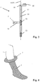
- Figure 3 shows a schematic side view of an embodiment of the tightening aid 1, in which the guide jaw 16 can additionally be moved up and down along the guide rail 17.
- the donning aid 1 also has a guide motor 50, for example a stepper motor, a spindle 51, the spatial alignment of which is given by a spindle longitudinal axis 52, and a slide 53.
- the spindle 51 is integrated in the guide rail 17.
- the longitudinal axis 52 of the spindle runs parallel to the longitudinal axis 29 of the guide rail 17, in particular it can coincide with it.
- the carriage 53 can be moved along the spindle 51.
- Carriage 53 and spindle 51 have mutually coordinated threads which are designed so that when the spindle 51 is rotated clockwise by the guide motor 50 in one direction along the longitudinal axis 52 of the spindle and when it is rotated counterclockwise in the other Direction moved along the longitudinal axis 52 of the spindle.
- the guide jaw 16 is firmly connected to the slide 53 and follows the movement of the slide 53 along the longitudinal axis 52 of the spindle. In the case of a carrier element 7 embedded in the guide jaws 16, this leads to a movement of the carrier element 7 along the longitudinal axis 29 of the guide rail 17.
- the embodiment of the donning aid 1 according to FIG Figure 3 a handle 54, which has elements 55 for controlling individual motors or all of them integrated in the tightening aid 1.
- FIG 4 An embodiment of the tightening aid 1 without guide jaws 16 and guide rail 17 is shown in operation.
- the carrier element 7 is covered by the part of the support stocking 2 that has not yet been unrolled.
- Figure 5 shows the interior of a carrier element 7, as it is for example in the embodiments according to the Figures 1-4 can be used.
- this has approximately the shape of a rotational torus, which is defined by a large radius 19, a small radius 20 and a circular line 21.
- a propulsion unit 5 forms the entire surface of the carrier element 7.
- the propulsion unit 5 is in direct contact with the support stocking 2. Furthermore, the propulsion unit 5 rotates around the circular line 21, which leads to a constant compression and expansion of the Propulsion unit 5 leads.
- the propulsion unit 5 is made of an elastic material, for example rubber or an elastic plastic.
- the propulsion unit 5 itself is in direct contact with a propulsion connection piece 6, which in the embodiment shown is designed as part of a drive unit 3.
- Each drive unit 3 is designed in the shape of a cylinder, the propulsion connector 6 forming the jacket of the cylinder.
- the propulsion connector 6 is driven via a planetary gear, comprising a sun gear 4.1 and a planet gear 4.2.
- the propulsion connector 6 has internal toothing in some areas (see also FIG Figures 6-8 for detailed representations). Via this toothing, the jacking connector 6 is driven by two, three or more planet gears 4.2.
- the sun gear 4.1 itself is connected via a drive shaft 14 to a drive motor 13, which is spatially limited by a motor housing 13.1, and can be rotated by the latter.
- the rotating parts of propulsion connector 6, planetary gear 4 and drive shaft 14 are supported by non-rotating parts via a bearing 11, which does not prevent the rotational movement of these parts.
- the non-rotating parts include a fixing block 8, one or more connecting elements 9 and the motor housing 13.1.
- the connecting elements 9 are anchored in the fixing block 8. It is these non-rotating parts that give the support element 7 the necessary stability by being torsionally stable and pressure-resistant.
- Figure 6 uses a central longitudinal section through the cylindrical drive unit 3 to illustrate the structure of the same as in a carrier element 7 according to FIG Figure 5 can be used, in detail.
- the arrangement of the moving parts drive shaft 14, planetary gear 4, which has a sun gear 4.1 and a planet gear 4.2, and propulsion connector 6 is shown.
- the arrangement of the non-moving parts motor housing 13.1, fixing block 8 and connecting element 9, which in the embodiment shown is located in a plane in front of and / or behind the cutting plane, is shown.
- a bearing 11 transfers the mechanical stability of the non-moving parts to the moving parts without hindering their rotational movement.
- the propulsion connector 6 is driven in the area of the planetary gear 4.2. In this area, the jack connector 6 is serrated on the inside. This allows sun gear 4.1, planet gear 4.2 and propulsion connector 6 in the in Figure 6 Embodiment shown as a planetary gear in stand translation.
- the propulsion unit 5 is in flat, rotationally fixed contact with the propulsion connection piece 6.
- the propulsion connection piece 5 can also be dispensed with by appropriate design of the inside of the propulsion unit 5.
- knobs 10 or other elements such as hooks or clamps or a non-slip coating which promote interlocking of the support stocking 2 with the propulsion unit 5 and thus prevent the support stocking 2 from slipping off and the carrier element 7 from rotating empty.
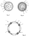
- Figures 7 and 8 show cuts along the in Figure 6 indexed levels.
- Figure 7 shows in a section along BB in more detail how the rotation of the drive shaft 14 caused by the drive motor 13 is transmitted via the planetary gear 4 to the propulsion connector 6 and the propulsion unit 5.
- the connecting elements 9 penetrating the sectional plane.
- the fixing block 8 itself has no area which is located in the sectional plane.
- Figure 8 shows in a section along AA also in detail how the rotating parts propulsion connector 6 and propulsion unit 5 via the bearing 11 are carried by the non-rotating parts motor housing 13.1, fixing block 8 and connecting element 9.
- Figure 9 schematically shows the interior of an embodiment of the carrier element 7.
- the carrier element 7 has, in addition to drive units 3 and connecting elements 9, an elastic element 46, an adjusting mechanism 40, a sensor 47 and an opening / closing mechanism 48.
- the elastic element 46 provides tension along the longitudinal axis of the carrier element 7.
- a carrier element 7 is shown in the form of a rotation torus, with which the said longitudinal axis of the carrier element 7 is identical to the circular line 21 of the rotation torus. This tension leads to a clamping effect on the body part surrounded by the carrier element 7 during operation, which ultimately allows the carrier element 7 to be moved up and down along the body part.
- the sensor 47 measures the tensile force occurring along the longitudinal axis 21 of the carrier element 7 and sends a signal to the adjustment mechanism 40 as soon as a value falls below a predefined minimum value or is exceeded a previously defined maximum value.
- a contraction of the adjustment mechanism 40 along the longitudinal axis 21 of the carrier element 7 is initiated by the signal.
- an expansion of the adjustment mechanism 40 along the longitudinal axis 21 of the carrier element 7 is initiated accordingly.
- the opening / closing mechanism 48 ensures that the carrier element 7 can be opened, for example in order to simply remove the carrier element 7 from the body part after the support stocking 2 has been put on, or to position the carrier element 7 on the body part before the support stocking 2 is removed.
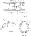
- FIG 10 A schematic representation of an embodiment of an adjustment mechanism 40 is shown, which serves to enlarge or reduce the area which is at least partially enclosed by the carrier element 7 during operation.
- it is a section perpendicular to the axis of rotation 18 which contains the longitudinal axis of the carrier element 7 or the circular line 21 of the rotation torus.
- the connecting elements 9 which change their length parallel to the longitudinal axis of the carrier element 7.
- the adjusting mechanism 40 is arranged between two connecting elements 9 which run straight and parallel in the region of the adjusting mechanism 40.
- the two connecting elements 9 are interrupted perpendicular to their longitudinal axis, as a result of which a first partial connecting area 44 and a second partial connecting area 45 are created.
- these partial connection areas correspond in the embodiment shown these partial connection areas to the previously introduced partial elements of the adjustment mechanism.
- the termination of these two partial connecting areas 44/45 is formed by a first fixed connecting piece 43.1 and a second fixed connecting piece 43.2.
- the first connecting piece 43.1 arranged in the first partial connecting area 44 carries an adjusting motor 41 and an adjusting gear 42, which at least partially has a thread.
- the connecting piece 43.2 arranged in the second partial connection area 45 has a threaded bore which is matched to the thread of the adjusting gear 42.
- the adjustment gear 42 can now be rotated via the adjustment motor 41, as a result of which the distance between the two partial connection areas 44/45 and thus the distance between the two fixing blocks, in which the connection elements 9 involved in the adjustment mechanism 40 on their side facing away from the adjustment mechanism 40 are anchored, changed.
- the adjustment mechanism 40 shown can be both an independent element within the carrier element 7 and a component of a drive unit 3.
- FIGS 11 and 12 show two embodiments of carrier elements 7 which have an adjustment mechanism 40.
- the adjustment mechanism 40 is integrated in the drive unit 3.
- the area of the carrier element 7 in which the carrier element 7 has no bend is lengthened or reduced.
- a support element 7 is thus realized which is able to at least partially enclose a body part, the at least partially enclosable surface being adjustable via the adjustment mechanism 40.
- Figure 12 schematically shows the inner life of a carrier element 7, which is able to completely enclose a body part.
- drive units 3 and units of the adjustment mechanism 40 are arranged alternately on the sides of an n-corner.
- a hexagon is shown in the figure, even if geometric shapes with a higher number of corners and / or rounded corners are better able to reproduce the cross-sectional shape of a body part.
- the drive units 3 themselves also have an adjustment mechanism 40.
- the shape of the carrier element 7 can be adjusted more precisely.
- Figure 13 shows an alternative embodiment of a donning aid 1 with guide rail 17 in operation, which is also in accordance with the invention.
- a state is shown in which the support stocking 2 is only partially pulled onto the body part, here the leg.
- the support stocking 2 is not rolled up on the support element 7 covered by the support stocking 2 before it is unrolled, but rather is only stretched by the support element 7.
- Figure 14 is a schematic detailed representation of the donning aid 1 according to Figure 13 .
- the surface of the carrier element 7 has both partial areas which perform a circumferential movement and partial areas which do not make a circular motion.
- the latter have a foot 25 and an extension 26, the extension 26 extending along the axis along which the pulling aid 1 moves to unwind and roll up the support stocking 2.
- the non-circulating sub-regions enable the connection of the carrier element 7 to the guide rail 17 without using a guide jaw. Furthermore, these areas create space to easily accommodate components of the tightening aid 1, such as driving motors, gears, propulsion connectors and holding and / or supporting elements. In the embodiment shown, the drive units are accommodated in the foot 25.
- the surrounding sub-areas have the propulsion unit 5, which is designed in the form of treadmills, which sub-areas of the extension 26 run around.
- a propulsion unit 5 is driven from the outside, that is to say from an area which does not enclose the self-contained propulsion unit 5. This happens because the propulsion unit 5 has areas into which hooks, or teeth or guide pins, which are on the propulsion connection piece 6 (in Figure 14 are hidden by the housing of the foot 25 and the propulsion unit 5). The rotational movement of the propulsion connector 6 driven by a motor is thus transmitted to the propulsion unit 5.
- the propulsion unit 5 alternatively driven from the inside, ie from an area which will be rotated by the propulsion unit 5.
Landscapes
- Manipulator (AREA)
- Orthopedics, Nursing, And Contraception (AREA)
- Invalid Beds And Related Equipment (AREA)
- Holders For Apparel And Elements Relating To Apparel (AREA)
- Professional, Industrial, Or Sporting Protective Garments (AREA)
- Sewing Machines And Sewing (AREA)
- Transmission Devices (AREA)
- Output Control And Ontrol Of Special Type Engine (AREA)
- Rehabilitation Tools (AREA)
Priority Applications (1)
| Application Number | Priority Date | Filing Date | Title |
|---|---|---|---|
| PL16767130T PL3340840T3 (pl) | 2015-08-27 | 2016-08-26 | Pomoc do zakładania dla pończoch podtrzymujących |
Applications Claiming Priority (2)
| Application Number | Priority Date | Filing Date | Title |
|---|---|---|---|
| CH01236/15A CH711453A2 (de) | 2015-08-27 | 2015-08-27 | Anziehhilfe für Stützstrümpfe. |
| PCT/CH2016/000111 WO2017031604A1 (de) | 2015-08-27 | 2016-08-26 | Anziehhilfe für stützstrümpfe |
Publications (2)
| Publication Number | Publication Date |
|---|---|
| EP3340840A1 EP3340840A1 (de) | 2018-07-04 |
| EP3340840B1 true EP3340840B1 (de) | 2020-07-15 |
Family
ID=58099220
Family Applications (1)
| Application Number | Title | Priority Date | Filing Date |
|---|---|---|---|
| EP16767130.4A Active EP3340840B1 (de) | 2015-08-27 | 2016-08-26 | Anziehhilfe für stützstrümpfe |
Country Status (12)
| Country | Link |
|---|---|
| US (1) | US10682001B2 (pl) |
| EP (1) | EP3340840B1 (pl) |
| JP (1) | JP6904631B2 (pl) |
| CN (1) | CN108289558B (pl) |
| BR (1) | BR112018003833B1 (pl) |
| CA (1) | CA2995513C (pl) |
| CH (1) | CH711453A2 (pl) |
| ES (1) | ES2824166T3 (pl) |
| IL (1) | IL257629B (pl) |
| PL (1) | PL3340840T3 (pl) |
| RU (1) | RU2723835C2 (pl) |
| WO (1) | WO2017031604A1 (pl) |
Cited By (1)
| Publication number | Priority date | Publication date | Assignee | Title |
|---|---|---|---|---|
| DE202022001859U1 (de) | 2022-08-20 | 2022-10-19 | Bernd Speidel | Anziehhilfe für Kompressionsstrümpfe und vergleichbare Einsatzzwecke |
Families Citing this family (7)
| Publication number | Priority date | Publication date | Assignee | Title |
|---|---|---|---|---|
| CN110051200B (zh) * | 2019-03-14 | 2020-08-28 | 杭州电子科技大学 | 全自动穿袜装置 |
| NL2025439B1 (en) * | 2020-04-28 | 2021-11-09 | Harpert Just Wouters | Assembly, device, system and method for donning a compressive garment |
| RU2771119C1 (ru) * | 2021-06-27 | 2022-04-26 | Алексей Николаевич Лысцов | Устройство для надевания компрессионного чулка |
| EP4691321A1 (en) * | 2023-03-24 | 2026-02-11 | National University Corporation Hamamatsu University School of Medicine | Wearing assistance tool and wearing assistance kit for elastic stocking, and wearing preparation method and wearing method for elastic stocking |
| US12137825B1 (en) * | 2023-05-02 | 2024-11-12 | Anna-Marie Brown | Underwear donning device, system and method |
| US20250366538A1 (en) * | 2024-06-03 | 2025-12-04 | Mark Supal | Easy Don Garment |
| US20260102009A1 (en) * | 2024-10-10 | 2026-04-16 | Torchward, Ltd. | Dressing assistance device and dressing assistance method |
Family Cites Families (13)
| Publication number | Priority date | Publication date | Assignee | Title |
|---|---|---|---|---|
| US636636A (en) | 1898-04-18 | 1899-11-07 | Orlando James Cole | Churn. |
| GB850165A (en) | 1955-12-22 | 1960-09-28 | John Neville Kimpton | Means facilitating putting on and taking of stockings |
| DE8906458U1 (de) | 1989-05-26 | 1989-07-13 | Pomplun, geb. Sommerfeld, Ursula, 4709 Bergkamen | Anziehhilfe für Anti-Thrombose-Strümpfe |
| NL9000361A (nl) * | 1990-02-15 | 1991-09-02 | Grol Beheer B V | Kous-aan/uittrekhulp. |
| US5069374A (en) * | 1990-09-11 | 1991-12-03 | Williamson Nina J | Elasticized stocking removal system |
| US5636774A (en) | 1993-11-23 | 1997-06-10 | Moscato; Giuseppe | Automatic device that may be independently managed by unable persons for wearing socks and similar articles |
| US6536636B1 (en) | 2001-11-26 | 2003-03-25 | Mcdonniel Thomas B. | Support hose applicator |
| AU2003257360A1 (en) * | 2002-09-16 | 2004-04-30 | Walter Zumbach | Dressing aids |
| DE102004032555A1 (de) | 2004-07-06 | 2006-02-16 | Olhöft, Peter | An- und Ausziehhilfe für textile, textilähnliche oder folienartige Stoffe |
| US20090120975A1 (en) * | 2007-11-09 | 2009-05-14 | Schoepe Erich G | Sock donning device |
| ITGE20100096A1 (it) * | 2010-09-06 | 2010-12-06 | Pietrino Forfori | Dispositivo infila calze elastiche |
| ITVI20120065A1 (it) * | 2012-03-23 | 2013-09-24 | Cristian Minardi | Apparecchio per indossare calze, calzini, calzettoni, calze ortopediche e simili. |
| US8356735B1 (en) * | 2012-06-15 | 2013-01-22 | Drakeford Melvin L | Method and apparatus for putting on and taking off socks or stockings |
-
2015
- 2015-08-27 CH CH01236/15A patent/CH711453A2/de unknown
-
2016
- 2016-08-26 PL PL16767130T patent/PL3340840T3/pl unknown
- 2016-08-26 WO PCT/CH2016/000111 patent/WO2017031604A1/de not_active Ceased
- 2016-08-26 US US15/754,674 patent/US10682001B2/en active Active
- 2016-08-26 BR BR112018003833-4A patent/BR112018003833B1/pt active IP Right Grant
- 2016-08-26 CN CN201680062933.0A patent/CN108289558B/zh active Active
- 2016-08-26 CA CA2995513A patent/CA2995513C/en active Active
- 2016-08-26 JP JP2018510351A patent/JP6904631B2/ja active Active
- 2016-08-26 RU RU2018109343A patent/RU2723835C2/ru active
- 2016-08-26 EP EP16767130.4A patent/EP3340840B1/de active Active
- 2016-08-26 ES ES16767130T patent/ES2824166T3/es active Active
- 2016-08-26 IL IL257629A patent/IL257629B/en unknown
Non-Patent Citations (1)
| Title |
|---|
| None * |
Cited By (1)
| Publication number | Priority date | Publication date | Assignee | Title |
|---|---|---|---|---|
| DE202022001859U1 (de) | 2022-08-20 | 2022-10-19 | Bernd Speidel | Anziehhilfe für Kompressionsstrümpfe und vergleichbare Einsatzzwecke |
Also Published As
| Publication number | Publication date |
|---|---|
| US10682001B2 (en) | 2020-06-16 |
| CA2995513C (en) | 2023-10-10 |
| BR112018003833B1 (pt) | 2022-07-26 |
| RU2018109343A3 (pl) | 2020-01-20 |
| JP2018525127A (ja) | 2018-09-06 |
| CN108289558A (zh) | 2018-07-17 |
| CH711453A2 (de) | 2017-02-28 |
| WO2017031604A1 (de) | 2017-03-02 |
| IL257629A (en) | 2018-04-30 |
| IL257629B (en) | 2022-08-01 |
| CA2995513A1 (en) | 2017-03-02 |
| BR112018003833A2 (pt) | 2018-09-25 |
| PL3340840T3 (pl) | 2021-03-08 |
| JP6904631B2 (ja) | 2021-07-21 |
| EP3340840A1 (de) | 2018-07-04 |
| CN108289558B (zh) | 2020-10-16 |
| ES2824166T3 (es) | 2021-05-11 |
| RU2723835C2 (ru) | 2020-06-17 |
| US20180242767A1 (en) | 2018-08-30 |
| RU2018109343A (ru) | 2019-09-30 |
Similar Documents
| Publication | Publication Date | Title |
|---|---|---|
| EP3340840B1 (de) | Anziehhilfe für stützstrümpfe | |
| EP3708128B1 (de) | Prothesenschaft und verfahren zur steuerung einer anpassung eines innenumfanges eines prothesenschaftes | |
| DE10349953B4 (de) | Vorrichtung zum Fixieren und Spannen zumindest eines Zugfadens für das Anlegen einer Neovagina | |
| DE102007023848B4 (de) | Schultergelenk | |
| EP3895267B1 (de) | Verfahren zur entfernung einer schirmfolie eines elektrischen kabels mittels einer rotativen abisoliermaschine, sowie vorrichtung zur unterstützung der entfernung einer schirmfolie eines elektrischen kabels | |
| EP3221015B1 (de) | Trainingsvorrichtung mit 3d-positionserfassung und deren betriebsverfahren | |
| DE102012204814B4 (de) | Ein zusammenklappbares Kompressionsgerät und Röntgengerät | |
| EP2892471A1 (de) | Liner für eine prothese und prothese | |
| DE102012110051A1 (de) | Rückhaltevorrichtung, insbesondere für Trainingszwecke | |
| EP3033051B1 (de) | Prothesenschaft mit einführhilfseinrichtung | |
| DE2659227A1 (de) | Vorrichtung zum kraefteausgleich bei markisen | |
| DE102007023847A1 (de) | Schultergelenk | |
| DE102011012419A1 (de) | Vorrichtung zum zeitweiligen Halten eines Gegenstandes | |
| DE102010055998A1 (de) | Strumpfanzieh- und/oder -ausziehhilfe mit einem Halteelement zum Fixieren eines Strumpfes | |
| DE60129455T2 (de) | Walzvorrichtung für ringe | |
| EP2710917A1 (de) | Aufrollvorrichtung für ein Trageband einer Tasche | |
| DE102009048539B4 (de) | Vorrichtung zum Anziehen von Strümpfen | |
| DE271657C (de) | Vorrichtung zum Stutzen der Wandungen und Abschließen von Körperhöhlen insbesondere als Pessar dienend | |
| DE4012308A1 (de) | Vorrichtung zum heben oder positionieren einer kranken oder behinderten person | |
| EP3123947A1 (de) | Dehneinrichtung zum dehnen einer bauchdecke | |
| WO2010094677A1 (de) | Befestigungsvorrichtung für ein penisextensionsgerät | |
| EP2907432A1 (de) | Körperpflegevorrichtung | |
| WO2014154200A2 (de) | Vorrichtung und verfahren zur prüfung und/oder pflege eines schlauches | |
| DE102008045312A1 (de) | Spannvorrichtung | |
| DE102014108660A1 (de) | Nivellierwerkzeug zur Höhenverstellung von Wannenstützfüßen |
Legal Events
| Date | Code | Title | Description |
|---|---|---|---|
| STAA | Information on the status of an ep patent application or granted ep patent |
Free format text: STATUS: THE INTERNATIONAL PUBLICATION HAS BEEN MADE |
|
| PUAI | Public reference made under article 153(3) epc to a published international application that has entered the european phase |
Free format text: ORIGINAL CODE: 0009012 |
|
| STAA | Information on the status of an ep patent application or granted ep patent |
Free format text: STATUS: REQUEST FOR EXAMINATION WAS MADE |
|
| 17P | Request for examination filed |
Effective date: 20180313 |
|
| AK | Designated contracting states |
Kind code of ref document: A1 Designated state(s): AL AT BE BG CH CY CZ DE DK EE ES FI FR GB GR HR HU IE IS IT LI LT LU LV MC MK MT NL NO PL PT RO RS SE SI SK SM TR |
|
| AX | Request for extension of the european patent |
Extension state: BA ME |
|
| DAV | Request for validation of the european patent (deleted) | ||
| DAX | Request for extension of the european patent (deleted) | ||
| GRAP | Despatch of communication of intention to grant a patent |
Free format text: ORIGINAL CODE: EPIDOSNIGR1 |
|
| STAA | Information on the status of an ep patent application or granted ep patent |
Free format text: STATUS: GRANT OF PATENT IS INTENDED |
|
| INTG | Intention to grant announced |
Effective date: 20200120 |
|
| GRAS | Grant fee paid |
Free format text: ORIGINAL CODE: EPIDOSNIGR3 |
|
| GRAA | (expected) grant |
Free format text: ORIGINAL CODE: 0009210 |
|
| STAA | Information on the status of an ep patent application or granted ep patent |
Free format text: STATUS: THE PATENT HAS BEEN GRANTED |
|
| AK | Designated contracting states |
Kind code of ref document: B1 Designated state(s): AL AT BE BG CH CY CZ DE DK EE ES FI FR GB GR HR HU IE IS IT LI LT LU LV MC MK MT NL NO PL PT RO RS SE SI SK SM TR |
|
| REG | Reference to a national code |
Ref country code: GB Ref legal event code: FG4D Free format text: NOT ENGLISH Ref country code: CH Ref legal event code: EP |
|
| REG | Reference to a national code |
Ref country code: DE Ref legal event code: R096 Ref document number: 502016010535 Country of ref document: DE |
|
| REG | Reference to a national code |
Ref country code: IE Ref legal event code: FG4D Free format text: LANGUAGE OF EP DOCUMENT: GERMAN |
|
| REG | Reference to a national code |
Ref country code: AT Ref legal event code: REF Ref document number: 1290005 Country of ref document: AT Kind code of ref document: T Effective date: 20200815 |
|
| REG | Reference to a national code |
Ref country code: NL Ref legal event code: FP |
|
| REG | Reference to a national code |
Ref country code: SE Ref legal event code: TRGR |
|
| REG | Reference to a national code |
Ref country code: LT Ref legal event code: MG4D |
|
| REG | Reference to a national code |
Ref country code: CH Ref legal event code: NV Representative=s name: FREI PATENTANWALTSBUERO AG, CH |
|
| PG25 | Lapsed in a contracting state [announced via postgrant information from national office to epo] |
Ref country code: LT Free format text: LAPSE BECAUSE OF FAILURE TO SUBMIT A TRANSLATION OF THE DESCRIPTION OR TO PAY THE FEE WITHIN THE PRESCRIBED TIME-LIMIT Effective date: 20200715 Ref country code: PT Free format text: LAPSE BECAUSE OF FAILURE TO SUBMIT A TRANSLATION OF THE DESCRIPTION OR TO PAY THE FEE WITHIN THE PRESCRIBED TIME-LIMIT Effective date: 20201116 Ref country code: HR Free format text: LAPSE BECAUSE OF FAILURE TO SUBMIT A TRANSLATION OF THE DESCRIPTION OR TO PAY THE FEE WITHIN THE PRESCRIBED TIME-LIMIT Effective date: 20200715 Ref country code: BG Free format text: LAPSE BECAUSE OF FAILURE TO SUBMIT A TRANSLATION OF THE DESCRIPTION OR TO PAY THE FEE WITHIN THE PRESCRIBED TIME-LIMIT Effective date: 20201015 Ref country code: GR Free format text: LAPSE BECAUSE OF FAILURE TO SUBMIT A TRANSLATION OF THE DESCRIPTION OR TO PAY THE FEE WITHIN THE PRESCRIBED TIME-LIMIT Effective date: 20201016 Ref country code: NO Free format text: LAPSE BECAUSE OF FAILURE TO SUBMIT A TRANSLATION OF THE DESCRIPTION OR TO PAY THE FEE WITHIN THE PRESCRIBED TIME-LIMIT Effective date: 20201015 Ref country code: FI Free format text: LAPSE BECAUSE OF FAILURE TO SUBMIT A TRANSLATION OF THE DESCRIPTION OR TO PAY THE FEE WITHIN THE PRESCRIBED TIME-LIMIT Effective date: 20200715 |
|
| PG25 | Lapsed in a contracting state [announced via postgrant information from national office to epo] |
Ref country code: IS Free format text: LAPSE BECAUSE OF FAILURE TO SUBMIT A TRANSLATION OF THE DESCRIPTION OR TO PAY THE FEE WITHIN THE PRESCRIBED TIME-LIMIT Effective date: 20201115 Ref country code: RS Free format text: LAPSE BECAUSE OF FAILURE TO SUBMIT A TRANSLATION OF THE DESCRIPTION OR TO PAY THE FEE WITHIN THE PRESCRIBED TIME-LIMIT Effective date: 20200715 Ref country code: LV Free format text: LAPSE BECAUSE OF FAILURE TO SUBMIT A TRANSLATION OF THE DESCRIPTION OR TO PAY THE FEE WITHIN THE PRESCRIBED TIME-LIMIT Effective date: 20200715 |
|
| REG | Reference to a national code |
Ref country code: DE Ref legal event code: R097 Ref document number: 502016010535 Country of ref document: DE |
|
| PG25 | Lapsed in a contracting state [announced via postgrant information from national office to epo] |
Ref country code: SM Free format text: LAPSE BECAUSE OF FAILURE TO SUBMIT A TRANSLATION OF THE DESCRIPTION OR TO PAY THE FEE WITHIN THE PRESCRIBED TIME-LIMIT Effective date: 20200715 Ref country code: EE Free format text: LAPSE BECAUSE OF FAILURE TO SUBMIT A TRANSLATION OF THE DESCRIPTION OR TO PAY THE FEE WITHIN THE PRESCRIBED TIME-LIMIT Effective date: 20200715 Ref country code: DK Free format text: LAPSE BECAUSE OF FAILURE TO SUBMIT A TRANSLATION OF THE DESCRIPTION OR TO PAY THE FEE WITHIN THE PRESCRIBED TIME-LIMIT Effective date: 20200715 Ref country code: CZ Free format text: LAPSE BECAUSE OF FAILURE TO SUBMIT A TRANSLATION OF THE DESCRIPTION OR TO PAY THE FEE WITHIN THE PRESCRIBED TIME-LIMIT Effective date: 20200715 Ref country code: RO Free format text: LAPSE BECAUSE OF FAILURE TO SUBMIT A TRANSLATION OF THE DESCRIPTION OR TO PAY THE FEE WITHIN THE PRESCRIBED TIME-LIMIT Effective date: 20200715 Ref country code: LU Free format text: LAPSE BECAUSE OF NON-PAYMENT OF DUE FEES Effective date: 20200826 |
|
| REG | Reference to a national code |
Ref country code: ES Ref legal event code: FG2A Ref document number: 2824166 Country of ref document: ES Kind code of ref document: T3 Effective date: 20210511 |
|
| PLBE | No opposition filed within time limit |
Free format text: ORIGINAL CODE: 0009261 |
|
| STAA | Information on the status of an ep patent application or granted ep patent |
Free format text: STATUS: NO OPPOSITION FILED WITHIN TIME LIMIT |
|
| PG25 | Lapsed in a contracting state [announced via postgrant information from national office to epo] |
Ref country code: AL Free format text: LAPSE BECAUSE OF FAILURE TO SUBMIT A TRANSLATION OF THE DESCRIPTION OR TO PAY THE FEE WITHIN THE PRESCRIBED TIME-LIMIT Effective date: 20200715 |
|
| 26N | No opposition filed |
Effective date: 20210416 |
|
| PG25 | Lapsed in a contracting state [announced via postgrant information from national office to epo] |
Ref country code: SK Free format text: LAPSE BECAUSE OF FAILURE TO SUBMIT A TRANSLATION OF THE DESCRIPTION OR TO PAY THE FEE WITHIN THE PRESCRIBED TIME-LIMIT Effective date: 20200715 |
|
| PG25 | Lapsed in a contracting state [announced via postgrant information from national office to epo] |
Ref country code: SI Free format text: LAPSE BECAUSE OF FAILURE TO SUBMIT A TRANSLATION OF THE DESCRIPTION OR TO PAY THE FEE WITHIN THE PRESCRIBED TIME-LIMIT Effective date: 20200715 Ref country code: IE Free format text: LAPSE BECAUSE OF NON-PAYMENT OF DUE FEES Effective date: 20200826 |
|
| PG25 | Lapsed in a contracting state [announced via postgrant information from national office to epo] |
Ref country code: TR Free format text: LAPSE BECAUSE OF FAILURE TO SUBMIT A TRANSLATION OF THE DESCRIPTION OR TO PAY THE FEE WITHIN THE PRESCRIBED TIME-LIMIT Effective date: 20200715 Ref country code: MT Free format text: LAPSE BECAUSE OF FAILURE TO SUBMIT A TRANSLATION OF THE DESCRIPTION OR TO PAY THE FEE WITHIN THE PRESCRIBED TIME-LIMIT Effective date: 20200715 Ref country code: CY Free format text: LAPSE BECAUSE OF FAILURE TO SUBMIT A TRANSLATION OF THE DESCRIPTION OR TO PAY THE FEE WITHIN THE PRESCRIBED TIME-LIMIT Effective date: 20200715 |
|
| PG25 | Lapsed in a contracting state [announced via postgrant information from national office to epo] |
Ref country code: MK Free format text: LAPSE BECAUSE OF FAILURE TO SUBMIT A TRANSLATION OF THE DESCRIPTION OR TO PAY THE FEE WITHIN THE PRESCRIBED TIME-LIMIT Effective date: 20200715 Ref country code: MC Free format text: LAPSE BECAUSE OF FAILURE TO SUBMIT A TRANSLATION OF THE DESCRIPTION OR TO PAY THE FEE WITHIN THE PRESCRIBED TIME-LIMIT Effective date: 20200715 |
|
| REG | Reference to a national code |
Ref country code: AT Ref legal event code: MM01 Ref document number: 1290005 Country of ref document: AT Kind code of ref document: T Effective date: 20210826 |
|
| PG25 | Lapsed in a contracting state [announced via postgrant information from national office to epo] |
Ref country code: AT Free format text: LAPSE BECAUSE OF NON-PAYMENT OF DUE FEES Effective date: 20210826 |
|
| PGFP | Annual fee paid to national office [announced via postgrant information from national office to epo] |
Ref country code: NL Payment date: 20250821 Year of fee payment: 10 |
|
| PGFP | Annual fee paid to national office [announced via postgrant information from national office to epo] |
Ref country code: ES Payment date: 20250926 Year of fee payment: 10 |
|
| PGFP | Annual fee paid to national office [announced via postgrant information from national office to epo] |
Ref country code: DE Payment date: 20250820 Year of fee payment: 10 |
|
| PGFP | Annual fee paid to national office [announced via postgrant information from national office to epo] |
Ref country code: PL Payment date: 20250818 Year of fee payment: 10 Ref country code: IT Payment date: 20250825 Year of fee payment: 10 |
|
| PGFP | Annual fee paid to national office [announced via postgrant information from national office to epo] |
Ref country code: GB Payment date: 20250821 Year of fee payment: 10 Ref country code: BE Payment date: 20250820 Year of fee payment: 10 |
|
| PGFP | Annual fee paid to national office [announced via postgrant information from national office to epo] |
Ref country code: FR Payment date: 20250828 Year of fee payment: 10 |
|
| PGFP | Annual fee paid to national office [announced via postgrant information from national office to epo] |
Ref country code: SE Payment date: 20250820 Year of fee payment: 10 Ref country code: CH Payment date: 20250901 Year of fee payment: 10 |