EP3339761A1 - Dispositif de réfrigération - Google Patents
Dispositif de réfrigération Download PDFInfo
- Publication number
- EP3339761A1 EP3339761A1 EP16837058.3A EP16837058A EP3339761A1 EP 3339761 A1 EP3339761 A1 EP 3339761A1 EP 16837058 A EP16837058 A EP 16837058A EP 3339761 A1 EP3339761 A1 EP 3339761A1
- Authority
- EP
- European Patent Office
- Prior art keywords
- heat exchanger
- temperature
- outdoor heat
- indoor
- outdoor
- Prior art date
- Legal status (The legal status is an assumption and is not a legal conclusion. Google has not performed a legal analysis and makes no representation as to the accuracy of the status listed.)
- Withdrawn
Links
- 238000005057 refrigeration Methods 0.000 title claims abstract description 46
- 238000010257 thawing Methods 0.000 claims abstract description 107
- 230000007423 decrease Effects 0.000 claims abstract description 17
- 239000003507 refrigerant Substances 0.000 claims description 52
- 238000005070 sampling Methods 0.000 claims description 9
- 238000007906 compression Methods 0.000 claims description 6
- 230000005465 channeling Effects 0.000 claims description 2
- 230000003247 decreasing effect Effects 0.000 description 12
- 238000010792 warming Methods 0.000 description 12
- 230000006870 function Effects 0.000 description 7
- 239000007788 liquid Substances 0.000 description 7
- 238000001816 cooling Methods 0.000 description 6
- 238000012986 modification Methods 0.000 description 6
- 230000004048 modification Effects 0.000 description 6
- ATJFFYVFTNAWJD-UHFFFAOYSA-N Tin Chemical compound [Sn] ATJFFYVFTNAWJD-UHFFFAOYSA-N 0.000 description 4
- 230000000694 effects Effects 0.000 description 4
- 238000000034 method Methods 0.000 description 4
- 238000002360 preparation method Methods 0.000 description 3
- 238000010586 diagram Methods 0.000 description 2
- 238000005259 measurement Methods 0.000 description 2
- 238000012546 transfer Methods 0.000 description 2
- 238000004891 communication Methods 0.000 description 1
- 239000000155 melt Substances 0.000 description 1
Images


Classifications
-
- F—MECHANICAL ENGINEERING; LIGHTING; HEATING; WEAPONS; BLASTING
- F24—HEATING; RANGES; VENTILATING
- F24F—AIR-CONDITIONING; AIR-HUMIDIFICATION; VENTILATION; USE OF AIR CURRENTS FOR SCREENING
- F24F11/00—Control or safety arrangements
- F24F11/30—Control or safety arrangements for purposes related to the operation of the system, e.g. for safety or monitoring
- F24F11/41—Defrosting; Preventing freezing
- F24F11/42—Defrosting; Preventing freezing of outdoor units
-
- F—MECHANICAL ENGINEERING; LIGHTING; HEATING; WEAPONS; BLASTING
- F24—HEATING; RANGES; VENTILATING
- F24F—AIR-CONDITIONING; AIR-HUMIDIFICATION; VENTILATION; USE OF AIR CURRENTS FOR SCREENING
- F24F1/00—Room units for air-conditioning, e.g. separate or self-contained units or units receiving primary air from a central station
- F24F1/0007—Indoor units, e.g. fan coil units
- F24F1/0043—Indoor units, e.g. fan coil units characterised by mounting arrangements
- F24F1/0057—Indoor units, e.g. fan coil units characterised by mounting arrangements mounted in or on a wall
-
- F—MECHANICAL ENGINEERING; LIGHTING; HEATING; WEAPONS; BLASTING
- F24—HEATING; RANGES; VENTILATING
- F24F—AIR-CONDITIONING; AIR-HUMIDIFICATION; VENTILATION; USE OF AIR CURRENTS FOR SCREENING
- F24F1/00—Room units for air-conditioning, e.g. separate or self-contained units or units receiving primary air from a central station
- F24F1/0007—Indoor units, e.g. fan coil units
- F24F1/0059—Indoor units, e.g. fan coil units characterised by heat exchangers
- F24F1/0063—Indoor units, e.g. fan coil units characterised by heat exchangers by the mounting or arrangement of the heat exchangers
-
- F—MECHANICAL ENGINEERING; LIGHTING; HEATING; WEAPONS; BLASTING
- F24—HEATING; RANGES; VENTILATING
- F24F—AIR-CONDITIONING; AIR-HUMIDIFICATION; VENTILATION; USE OF AIR CURRENTS FOR SCREENING
- F24F1/00—Room units for air-conditioning, e.g. separate or self-contained units or units receiving primary air from a central station
- F24F1/0007—Indoor units, e.g. fan coil units
- F24F1/0071—Indoor units, e.g. fan coil units with means for purifying supplied air
- F24F1/0073—Indoor units, e.g. fan coil units with means for purifying supplied air characterised by the mounting or arrangement of filters
-
- F—MECHANICAL ENGINEERING; LIGHTING; HEATING; WEAPONS; BLASTING
- F24—HEATING; RANGES; VENTILATING
- F24F—AIR-CONDITIONING; AIR-HUMIDIFICATION; VENTILATION; USE OF AIR CURRENTS FOR SCREENING
- F24F11/00—Control or safety arrangements
- F24F11/62—Control or safety arrangements characterised by the type of control or by internal processing, e.g. using fuzzy logic, adaptive control or estimation of values
- F24F11/63—Electronic processing
- F24F11/64—Electronic processing using pre-stored data
-
- F—MECHANICAL ENGINEERING; LIGHTING; HEATING; WEAPONS; BLASTING
- F24—HEATING; RANGES; VENTILATING
- F24F—AIR-CONDITIONING; AIR-HUMIDIFICATION; VENTILATION; USE OF AIR CURRENTS FOR SCREENING
- F24F11/00—Control or safety arrangements
- F24F11/62—Control or safety arrangements characterised by the type of control or by internal processing, e.g. using fuzzy logic, adaptive control or estimation of values
- F24F11/63—Electronic processing
- F24F11/65—Electronic processing for selecting an operating mode
-
- F—MECHANICAL ENGINEERING; LIGHTING; HEATING; WEAPONS; BLASTING
- F24—HEATING; RANGES; VENTILATING
- F24F—AIR-CONDITIONING; AIR-HUMIDIFICATION; VENTILATION; USE OF AIR CURRENTS FOR SCREENING
- F24F11/00—Control or safety arrangements
- F24F11/70—Control systems characterised by their outputs; Constructional details thereof
- F24F11/80—Control systems characterised by their outputs; Constructional details thereof for controlling the temperature of the supplied air
- F24F11/87—Control systems characterised by their outputs; Constructional details thereof for controlling the temperature of the supplied air by controlling absorption or discharge of heat in outdoor units
- F24F11/871—Control systems characterised by their outputs; Constructional details thereof for controlling the temperature of the supplied air by controlling absorption or discharge of heat in outdoor units by controlling outdoor fans
-
- F—MECHANICAL ENGINEERING; LIGHTING; HEATING; WEAPONS; BLASTING
- F24—HEATING; RANGES; VENTILATING
- F24F—AIR-CONDITIONING; AIR-HUMIDIFICATION; VENTILATION; USE OF AIR CURRENTS FOR SCREENING
- F24F11/00—Control or safety arrangements
- F24F11/89—Arrangement or mounting of control or safety devices
-
- F—MECHANICAL ENGINEERING; LIGHTING; HEATING; WEAPONS; BLASTING
- F25—REFRIGERATION OR COOLING; COMBINED HEATING AND REFRIGERATION SYSTEMS; HEAT PUMP SYSTEMS; MANUFACTURE OR STORAGE OF ICE; LIQUEFACTION SOLIDIFICATION OF GASES
- F25B—REFRIGERATION MACHINES, PLANTS OR SYSTEMS; COMBINED HEATING AND REFRIGERATION SYSTEMS; HEAT PUMP SYSTEMS
- F25B47/00—Arrangements for preventing or removing deposits or corrosion, not provided for in another subclass
- F25B47/02—Defrosting cycles
- F25B47/022—Defrosting cycles hot gas defrosting
- F25B47/025—Defrosting cycles hot gas defrosting by reversing the cycle
-
- F—MECHANICAL ENGINEERING; LIGHTING; HEATING; WEAPONS; BLASTING
- F28—HEAT EXCHANGE IN GENERAL
- F28F—DETAILS OF HEAT-EXCHANGE AND HEAT-TRANSFER APPARATUS, OF GENERAL APPLICATION
- F28F27/00—Control arrangements or safety devices specially adapted for heat-exchange or heat-transfer apparatus
-
- F—MECHANICAL ENGINEERING; LIGHTING; HEATING; WEAPONS; BLASTING
- F24—HEATING; RANGES; VENTILATING
- F24F—AIR-CONDITIONING; AIR-HUMIDIFICATION; VENTILATION; USE OF AIR CURRENTS FOR SCREENING
- F24F2110/00—Control inputs relating to air properties
- F24F2110/10—Temperature
-
- F—MECHANICAL ENGINEERING; LIGHTING; HEATING; WEAPONS; BLASTING
- F24—HEATING; RANGES; VENTILATING
- F24F—AIR-CONDITIONING; AIR-HUMIDIFICATION; VENTILATION; USE OF AIR CURRENTS FOR SCREENING
- F24F2110/00—Control inputs relating to air properties
- F24F2110/10—Temperature
- F24F2110/12—Temperature of the outside air
-
- F—MECHANICAL ENGINEERING; LIGHTING; HEATING; WEAPONS; BLASTING
- F25—REFRIGERATION OR COOLING; COMBINED HEATING AND REFRIGERATION SYSTEMS; HEAT PUMP SYSTEMS; MANUFACTURE OR STORAGE OF ICE; LIQUEFACTION SOLIDIFICATION OF GASES
- F25B—REFRIGERATION MACHINES, PLANTS OR SYSTEMS; COMBINED HEATING AND REFRIGERATION SYSTEMS; HEAT PUMP SYSTEMS
- F25B2700/00—Sensing or detecting of parameters; Sensors therefor
- F25B2700/11—Sensor to detect if defrost is necessary
-
- F—MECHANICAL ENGINEERING; LIGHTING; HEATING; WEAPONS; BLASTING
- F25—REFRIGERATION OR COOLING; COMBINED HEATING AND REFRIGERATION SYSTEMS; HEAT PUMP SYSTEMS; MANUFACTURE OR STORAGE OF ICE; LIQUEFACTION SOLIDIFICATION OF GASES
- F25B—REFRIGERATION MACHINES, PLANTS OR SYSTEMS; COMBINED HEATING AND REFRIGERATION SYSTEMS; HEAT PUMP SYSTEMS
- F25B2700/00—Sensing or detecting of parameters; Sensors therefor
- F25B2700/21—Temperatures
- F25B2700/2106—Temperatures of fresh outdoor air
-
- F—MECHANICAL ENGINEERING; LIGHTING; HEATING; WEAPONS; BLASTING
- F25—REFRIGERATION OR COOLING; COMBINED HEATING AND REFRIGERATION SYSTEMS; HEAT PUMP SYSTEMS; MANUFACTURE OR STORAGE OF ICE; LIQUEFACTION SOLIDIFICATION OF GASES
- F25B—REFRIGERATION MACHINES, PLANTS OR SYSTEMS; COMBINED HEATING AND REFRIGERATION SYSTEMS; HEAT PUMP SYSTEMS
- F25B2700/00—Sensing or detecting of parameters; Sensors therefor
- F25B2700/21—Temperatures
- F25B2700/2116—Temperatures of a condenser
- F25B2700/21161—Temperatures of a condenser of the fluid heated by the condenser
-
- F—MECHANICAL ENGINEERING; LIGHTING; HEATING; WEAPONS; BLASTING
- F25—REFRIGERATION OR COOLING; COMBINED HEATING AND REFRIGERATION SYSTEMS; HEAT PUMP SYSTEMS; MANUFACTURE OR STORAGE OF ICE; LIQUEFACTION SOLIDIFICATION OF GASES
- F25B—REFRIGERATION MACHINES, PLANTS OR SYSTEMS; COMBINED HEATING AND REFRIGERATION SYSTEMS; HEAT PUMP SYSTEMS
- F25B2700/00—Sensing or detecting of parameters; Sensors therefor
- F25B2700/21—Temperatures
- F25B2700/2117—Temperatures of an evaporator
- F25B2700/21171—Temperatures of an evaporator of the fluid cooled by the evaporator
Definitions
- the present invention relates to a refrigeration apparatus provided with a refrigeration circuit.
- a defrosting operation is performed in order to remove frost forming on an outdoor heat exchanger.
- Patent Literature 1 Japanese Laid-open Patent Publication No. 9-243210
- Patent Literature 2 Japanese Laid-open Patent Publication No. 10-103818
- the fact that the temperature of the outdoor heat exchanger has decreased to no higher than a predetermined value is sensed for the purpose of learning that frost has begun to form on an indoor heat exchanger in order to determine whether or not to start a defrosting operation for removing the frost on the outdoor heat exchanger.
- An object of the present invention is to prevent the performing of wasteful defrosting, in which the defrosting operation is started when no frost has formed on the outdoor heat exchanger.
- a refrigeration apparatus comprises: a refrigeration circuit configured to repeat a vapor-compression refrigeration cycle by channeling refrigerant sequentially through a compressor, an indoor heat exchanger, an expansion mechanism, and an outdoor heat exchanger; a first sensor configured to detect an indoor heat exchanger temperature of the indoor heat exchanger; and a second sensor configured to detect an outdoor heat exchanger temperature of the outdoor heat exchanger, wherein the refrigeration apparatus is configured to start a defrosting operation to defrost the outdoor heat exchanger when a first necessary condition and a second condition is met, is the first condition being that a continuous decrease of the indoor heat exchanger temperature detected by the first sensor continues over a first set time, the second necessary condition being that a continuous decrease of the outdoor heat exchanger temperature detected by the second sensor continues over a second set time.
- the conditions to start the defrosting operation are not only the first necessary condition, which is that a state in which a continuous decrease of the indoor heat exchanger temperature is detected by the first sensor continues over a first set time, but also a second necessary condition which is that a state in which a continuous decrease of the outdoor heat exchanger temperature is detected by the second sensor continues over a second set time, therefore cases of the temperature of the outdoor heat exchanger increasing due to no frost having formed on the outdoor heat exchanger in spite of the temperature of the indoor heat exchanger decreasing for reasons other than frost forming on the outdoor heat exchanger can be excluded from cases of starting a defrosting operation.
- a refrigeration apparatus is the refrigeration apparatus according to the first aspect, wherein the second necessary condition is determined to have been met when average values of sampling values of the outdoor heat exchanger temperature within respective predetermined sampling times, detected by the second sensor, continues to not increase for at least a predetermined number of times.
- a refrigeration apparatus is the refrigeration apparatus according to the first aspect, further comprising a third sensor configured to detect an outside air temperature at a location where the outdoor heat exchanger is installed, wherein a third necessary condition is that the outdoor heat exchanger temperature detected by the second sensor is lower than a defrosting start temperature set according to the outside air temperature detected by the third sensor and an operating frequency of the compressor, and the refrigeration apparatus is configured to start the defrosting operation when the first necessary condition, the second necessary condition, and the third necessary condition have been simultaneously met.
- a refrigeration apparatus is the refrigeration apparatus according to the third aspect, wherein the third necessary condition is a condition that a time period during which the outdoor heat exchanger temperature is lower than the defrosting start temperature continues over a third set time.
- the performing of wasteful defrosting can be consistently prevented.
- FIGS. 1 and 2 An air conditioner is described below as an example of a refrigeration apparatus according to an embodiment of the present invention.
- An air conditioner 1 shown in FIG. 1 is provided with an indoor unit 2 attached to a wall surface WL or the like indoors, and an outdoor unit 3 installed outdoors.
- FIG. 2 is a circuit diagram of the air conditioner 1.
- This air conditioner 1 is provided with a refrigeration circuit 10, and is able to perform a vapor-compression refrigeration cycle by causing a refrigerant inside the refrigeration circuit 10 to circulate.
- the indoor unit 2 and the outdoor unit 3 are connected by a communication pipe 4.
- the refrigeration circuit 10 is provided with a compressor 11, a four-way switching valve 12, an outdoor heat exchanger 13, an expansion mechanism 14, an accumulator 15, and an indoor heat exchanger 16.
- the compressor 11, which takes in refrigerant from an intake port and discharges compressed refrigerant from a discharge port, blows the refrigerant discharged from the discharge port toward a first port of the four-way switching valve 12.
- the four-way switching valve 12 allows refrigerant to flow between the first port and a fourth port while simultaneously allowing refrigerant to flow between a second port and a third port, as shown by the dashed lines.
- the four-way switching valve 12 allows refrigerant to flow between the first port and the second port while simultaneously allowing refrigerant to flow between the third port and the fourth port, as shown by the solid lines.
- the outdoor heat exchanger 13 has a gas-side outlet/inlet for mainly allowing gas refrigerant to flow between the outdoor heat exchanger 13 and the second port of the four-way switching valve 12, and also has a liquid-side outlet/inlet for mainly allowing liquid refrigerant to flow between the outdoor heat exchanger 13 and the expansion mechanism 14.
- the outdoor heat exchanger 13 allows heat to be exchanged between outdoor air and refrigerant flowing through heat transfer tubes (not shown) connected between the liquid-side outlet/inlet and the gas-side outlet/inlet of the outdoor heat exchanger 13.
- the expansion mechanism 14 is disposed between the outdoor heat exchanger 13 and the indoor heat exchanger 16.
- the expansion mechanism 14 has the function of expanding and decompressing the refrigerant flowing between the outdoor heat exchanger 13 and the indoor heat exchanger 16.
- the indoor heat exchanger 16 has a liquid-side outlet/inlet for mainly allowing liquid refrigerant to flow between the indoor heat exchanger 16 and the expansion mechanism 14, and also has a gas-side outlet/inlet for mainly allowing gas refrigerant to flow between the indoor heat exchanger 16 and the fourth port of the four-way switching valve 12.
- the indoor heat exchanger 16 allows heat to be exchanged between indoor air and the refrigerant flowing through heat transfer tubes 16a (see FIG. 3 ) connected between the liquid-side outlet/inlet and the gas-side outlet/inlet of the indoor heat exchanger 16.
- An accumulator 15 is disposed between the third port of the four-way switching valve 12 and the intake port of the compressor 11.
- refrigerant flowing from the third port of the four-way switching valve 12 to the compressor 11 is separated into gas refrigerant and liquid refrigerant.
- Mainly gas refrigerant is supplied from the accumulator 15 to the intake port of the compressor 11.
- the outdoor unit 3 is provided with an outdoor fan 21 for generating an air flow of outdoor air through the outdoor heat exchanger 13.
- the outdoor unit 3 is also provided with an outdoor temperature sensor 22 for measuring the temperature of outdoor air, and an outdoor heat exchanger temperature sensor 23 for measuring the temperature of the outdoor heat exchanger 13.
- the outdoor unit 3 is provided with an outdoor-side control device 24 that controls the compressor 11, the four-way switching valve 12, the expansion mechanism 14, and the outdoor fan 21.
- This outdoor-side control device 24 includes, e.g., a CPU (not shown) and memory (not shown), and the outdoor-side control device 24 is configured to be able to control the outdoor unit 3 in accordance with stored programs and the like.
- the outdoor-side control device 24 is connected to the outdoor temperature sensor 22 and the outdoor heat exchanger temperature sensor 23 in order to receive signals pertaining to the temperatures measured by the outdoor temperature sensor 22 and the outdoor heat exchanger temperature sensor 23.
- the indoor unit 2 is provided with an indoor fan 31 for generating an air flow of indoor air through the indoor heat exchanger 16.
- the indoor unit 2 is also provided with an indoor temperature sensor 32 for measuring the temperature of indoor air, and an indoor heat exchanger temperature sensor 33 for measuring the temperature of the indoor heat exchanger 16.
- the indoor unit 2 is provided with an indoor-side control device 34 that controls the indoor fan 31.
- This indoor-side control device 34 includes, e.g., a CPU (not shown) and memory (not shown), and the indoor-side control device 34 is configured to be able to control the outdoor unit 3 in accordance with stored programs and the like.
- the indoor-side control device 34 is connected to the indoor temperature sensor 32 and the indoor heat exchanger temperature sensor 33 in order to receive signals pertaining to the temperatures measured by the indoor temperature sensor 32 and the indoor heat exchanger temperature sensor 33.
- the outdoor-side control device 24 and the indoor-side control device 34 are connected to each other by a signal line, and are configured to be able to send and receive signals to and from each other.
- FIG. 3 shows a cross-section of the indoor unit, sectioned along line I-I in FIG. 1 .
- the indoor unit 2 is provided with a casing 41, the indoor heat exchanger 16, the indoor fan 31, an air filter 42, a horizontal flap 43, and a vertical flap 49.
- An upper-surface intake port 44 is provided to the upper-surface of the casing 41. Indoor air in the proximity to the upper-surface intake port 44 is taken into the casing 41 from the upper-surface intake port 44 due to the driving of the indoor fan 31, and is sent to the indoor heat exchanger 16, which is shaped like an upside-down "V" in cross-section.
- the dashed-line arrows A in FIG. 3 represent the flow of indoor air sent from the upper-surface intake port 44 to the indoor fan 31 via the indoor heat exchanger 16.
- a lower-surface intake port 45 and a blow-out port 46 are formed in the lower-surface of the casing 41.
- the lower-surface intake port 45 is provided nearer to the wall than the blow-out port 46, and is connected to the interior of the casing 41 by an intake flow channel 47.
- Indoor air in proximity to the lower-surface intake port 45 is taken into the casing 41 from the lower-surface intake port 45 by the driving of the indoor fan 31, and is sent through the intake flow channel 47 to the indoor heat exchanger 16.
- the dashed-line arrow B in FIG. 3 represents the flow of indoor air sent from the lower-surface intake port 45 to the indoor heat exchanger 16.
- the blow-out port 46 is provided nearer to the front-surface side of the indoor unit 2 than the lower-surface intake port 45, and is connected to the interior of the casing 41 by a blow-out flow channel 48.
- Indoor air taken in from the upper-surface intake port 44 and the lower-surface intake port 45 exchanges heat in the indoor heat exchanger 16, after which the indoor air is passed through the blow-out flow channel 48 and blown out from the blow-out port 46 into the room.
- the dashed-line arrow C in FIG. 3 represents the flow of air sent from the blow-out flow channel 48 into the room via the blow-out port 46.
- Two horizontal flaps 43 are turnably attached to the casing 41 in proximity to the blow-out port 46.
- the horizontal flaps 43 turned by a flap-driving motor (not shown), open and close the blow-out port 46 in accordance with the operating state of the indoor unit 2.
- the horizontal flaps 43 have the function of varying the blow-out direction of indoor air up and down so that indoor air blown out from the blow-out port 46 is guided in the direction desired by the user.
- the vertical flap 49 is turnably attached to the casing 41 in proximity to the blow-out port 46.
- the vertical flap 49 turned by a flap-driving motor (not shown), has the function varying the blow-out direction of indoor air left and right.
- the four-way switching valve 12 switches to the state of the dashed lines shown in FIG. 2 .
- high-temperature, high-pressure gas refrigerant discharged from the compressor 11 flows into the indoor heat exchanger 16 via the four-way switching valve 12.
- the indoor heat exchanger 16 functions as a condenser. Therefore, as the refrigerant flows through the indoor heat exchanger 16, the refrigerant warms the indoor air while being cooled by exchanging heat with the indoor air, and the refrigerant condenses and changes from gas refrigerant to liquid refrigerant.
- the low-temperature, high-pressure refrigerant is decompressed by the expansion mechanism 14 and changed to low-temperature, low-pressure refrigerant.
- the refrigerant Having flowed into the outdoor heat exchanger 13 via the expansion mechanism 14, the refrigerant is warmed by exchanging heat with outdoor air, and the refrigerant evaporates and changes from liquid refrigerant to gas refrigerant.
- the outdoor heat exchanger 13 functions as an evaporator.
- Refrigerant composed mainly of low-temperature gas refrigerant is then drawn into the compressor 11 from the outdoor heat exchanger 13 via the four-way switching valve 12 and the accumulator 15.
- the refrigerant is channeled sequentially through the compressor 11, the indoor heat exchanger 16, the expansion mechanism 14, and the outdoor heat exchanger 13, and the repetition of this vapor-compression refrigeration cycle is the forward cycle.
- the four-way switching valve 12 switches to the state of the solid lines shown in FIG. 2 .
- high-temperature, high-pressure gas refrigerant discharged from the compressor 11 flows into the outdoor heat exchanger 13 via the four-way switching valve 12.
- the outdoor heat exchanger 13 functions as a condenser. Therefore, as the refrigerant flows through the outdoor heat exchanger 13, the refrigerant is cooled by exchanging heat with the outdoor air, and the refrigerant condenses and changes from gas refrigerant to liquid refrigerant.
- the low-temperature, high-pressure refrigerant is decompressed by the expansion mechanism 14 and changed to low-temperature, low-pressure refrigerant.
- the refrigerant cools the indoor air and is warmed by exchanging heat with the indoor air, and the refrigerant evaporates and changes from liquid refrigerant to gas refrigerant.
- the indoor heat exchanger 16 functions as an evaporator.
- Refrigerant composed mainly of low-temperature gas refrigerant is then drawn into the compressor 11 from the indoor heat exchanger 16 via the four-way switching valve 12 and the accumulator 15.
- the reverse-cycle defrosting operation is performed in order to remove frost that has formed on the outdoor heat exchanger 13 due to the air-warming operation being performed. Therefore, operation switches to the reverse-cycle defrosting operation midway through the air-warming operation, and the air-warming operation is resumed when the reverse-cycle defrosting operation ends.
- the four-way switching valve 12 switches to the state of the solid lines shown in FIG. 2 . The same vapor-compression refrigeration cycle as the air-cooling operation is then repeated in the reverse-cycle defrosting operation as well.
- the cycle performed during the reverse-cycle defrosting operation is a reverse cycle, in which the vapor-compression refrigeration cycle is repeated with refrigerant being channeled sequentially through the compressor 11, the outdoor heat exchanger 13, the expansion mechanism 14, and the indoor heat exchanger 16.
- the outdoor unit 3 concludes that defrosting will be performed by the outdoor-side control device 24 when air-warming control is being performed, as shown in FIG. 3 .
- a defrosting start determination is described hereinafter.
- a defrosting request signal SG1 is transmitted from the outdoor-side control device 24 of the outdoor unit 3 to the indoor-side control device 34 of the indoor unit 2.
- the indoor-side control device 34 receives the defrosting request signal SG1
- the indoor unit 2 begins preparations for the defrosting operation.
- the indoor-side control device 34 leaves the indoor fan 31 on for some time after turning the electric heater off, and completes preparations for the defrosting operation when the electric heater has been cooled.
- the indoor-side control device 34 transmits a defrosting permit signal SG2 to the outdoor-side control device 24.
- the outdoor-side control device 24 begins defrosting control and transmits a signal SG3 indicating that defrosting is occurring to the indoor-side control device 34.
- a normal notification signal SG4 is transmitted from the outdoor-side control device 24 to notify the indoor-side control device 34 of the indoor unit 2 that the air conditioner will return to the normal air-warming operation.
- the indoor unit 2 having received the normal notification signal SG4, resumes air-warming control for the air-warming operation.
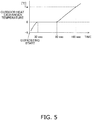
- the outdoor heat exchanger temperature during the reverse-cycle defrosting operation and before and after this operation is shown in FIG. 5 .
- the values shown on the time axis of FIG. 5 are one example for making the description easy to understand, and these values change due to the outside air temperature and/or the operating state of the air conditioner 1.
- the temperature of the outdoor heat exchanger 13 gradually increases until thirty seconds have elapsed since the start.
- the temperature of the outdoor heat exchanger 13 is maintained at 0°C.
- the frost formed on the outdoor heat exchanger 13 has melted away, the temperature of the outdoor heat exchanger 13 begins to increase.
- the frost has completely melted at the timepoint when ninety seconds has elapsed, and a temperature increase is therefore observed after ninety seconds has elapsed.
- the outdoor-side control device 24 monitors the outdoor heat exchanger temperature using the outdoor heat exchanger temperature sensor 23. When the outdoor-side control device 24 senses that the outdoor heat exchanger temperature has reached Ta°C due to the increase in the outdoor heat exchanger temperature beyond ninety seconds, the outdoor-side control device 24 concludes to end the reverse-cycle defrosting operation.
- the outdoor-side control device 24 stores a threshold value tr, and discerns whether the defrosting time is longer or shorter than the threshold value tr every time the reverse-cycle defrosting operation is performed.
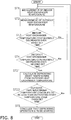
- FIG. 6 A summary of the determination to start the reverse-cycle defrosting operation is described using FIG. 6 .
- the indoor-side control device 34 of the indoor unit 2 measures an indoor heat exchanger temperature Tei of the indoor heat exchanger 16 using the indoor heat exchanger temperature sensor 33 (step ST1)
- the outdoor-side control device 24 of the outdoor unit 3 measures an outdoor heat exchanger temperature Teo of the outdoor heat exchanger 13 using the outdoor heat exchanger temperature sensor 23 (step ST2).
- FIG. 6 indicates that the indoor heat exchanger temperature Tei is measured prior to the outdoor heat exchanger temperature Teo measurement, but either one of these measurements may be performed first, or they may be performed simultaneously.
- step ST3 a determination is made as to whether or not the indoor heat exchanger temperature Tei has continuously decreased over a first set time (step ST3), and a determination is made as to whether or not the outdoor heat exchanger temperature Teo has continuously decreased over a second set time (step ST4).
- the former of these determinations is a determination of a first necessary condition
- the latter is a determination of a second necessary condition.
- the outdoor heat exchanger temperature Teo and the indoor heat exchanger temperature Tei may be compiled in either one of the indoor-side control device 34 and the outdoor-side control device 24, and whether or not both the first necessary condition and the second necessary condition have been satisfied may be determined by the control device that has the data on both the outdoor heat exchanger temperature Teo and the indoor heat exchanger temperature Tei.
- the indoor heat exchanger temperature Tei and the outdoor heat exchanger temperature Teo are repeatedly measured until the above-described first and second necessary conditions are met.
- the air conditioner 1 concludes, through the indoor-side control device 34 or the outdoor-side control device 24, that the defrosting operation is to be started (step ST5).
- step ST4 the step of determining whether or not the outdoor heat exchanger temperature Teo has continuously decreased over the second set time (step ST4) is carried out in step ST11 and step ST12.
- step ST11 the outdoor-side control device 24 samples the outdoor heat temperature n times over a certain time using a built-in sampling timer, and calculates the average value of the outdoor heat exchanger temperature Teo ( ⁇ Teo/n).
- the value n in this case is a predetermined natural number.
- the outdoor-side control device 24 or the indoor-side control device 34 determines that the outdoor heat exchanger temperature Teo has continually decreased over the second set time (step ST12).
- condition of the determination to start the defrosting operation is that two conditions, the first necessary condition and the second necessary condition, are met, but another necessary condition may be added in order to make the determination to start the defrosting operation.
- step ST21 in which a defrosting start temperature is calculated from the outdoor heat exchanger temperature
- step ST22 in which a determination of whether or not to avoid starting the defrosting operation is made using the defrosting start temperature.
- the outdoor-side control device 24 measures the outside air temperature Tout using the outdoor temperature sensor 22. The outdoor-side control device 24 then determines if the outside air temperature Tout is either below a defrosting determination outside air temperature Tdd, or equal to or greater than the defrosting determination outside air temperature Tdd. Additionally, the outdoor-side control device 24 determines whether the previous defrosting time tdf is longer or shorter than the threshold value tr, as was described in (3-1) above. The defrosting start temperature Tp is calculated according to these circumstances, using any of the following four formulas (1) to (4).
- f denotes the operating frequency of the compressor 11, and ⁇ , ⁇ 1, ⁇ 0, ⁇ 1 , ⁇ 0 , and v are positive constants.
- Tp is set within a predetermined range. Additionally, the constants of formulas (1) to (4) have been concluded from the results of measuring the outdoor heat exchanger temperature that prompts starting the defrosting operation (the defrosting start temperature Tp), outside air temperature Tout and operating frequency f.
- Tp ⁇ ⁇ ⁇ f + ⁇ 1 ⁇ Tout ⁇ ⁇ 1 when Tout ⁇ Tdd and tdf ⁇ tr
- Tp ⁇ ⁇ ⁇ f + ⁇ 0 ⁇ Tout ⁇ ⁇ 0 when Tout ⁇ Tdd and tdf ⁇ tr
- Tp ⁇ ⁇ ⁇ f + ⁇ 1 ⁇ Tout ⁇ ⁇ 1 + v when Tout ⁇ Tdd and tdf ⁇ tr
- Tp ⁇ ⁇ ⁇ f + ⁇ 0 ⁇ Tout ⁇ ⁇ 0 + v
- the indoor heat exchanger temperature Tei continuously decreasing over the first set time is described as an example of the first necessary condition when the determination is made to start the defrosting operation.
- the indoor heat exchanger temperature Tei is determined to have continuously decreased, the indoor heat exchanger temperature Tei is affected by the indoor temperature Tin, and rectifications may therefore be made using the indoor temperature Tin.
- the indoor-side control device 34 calculates the average value of temperature differences ⁇ Tei sampled over a certain time. When the average value of temperature differences ⁇ Tei has continued to decrease for k number of times, the indoor-side control device 34 determines that the first necessary condition has been met. Due to such a determination being made, a continuous decrease in the indoor heat exchanger temperature Tei can be determined while taking the effect of the indoor temperature Tin into account.
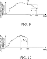
- the first necessary condition to be met is either that the average value Av ⁇ Tei of temperature differences ⁇ Tei continues to decrease for k number of times, or that the average value Av ⁇ Tei of temperature differences ⁇ Tei does not increase over a first set time Ts1.
- the average value Av ⁇ Tei of temperature differences ⁇ Tei does not increase but either remains at the same value or decreases from time t31 to time t32, as shown in FIG. 10 .
- the first necessary condition for starting defrosting is met at a comparatively earlier timing than in FIG. 9 .
- the first necessary condition for the air conditioner to start the defrosting operation is that a state in which a continuous decrease in the indoor heat exchanger temperature Tei of the indoor heat exchanger 16 is detected by the indoor heat exchanger temperature sensor 33 continues over a first set time.
- the second necessary condition is that a state in which a continuous decrease in the outdoor heat exchanger temperature Teo of the outdoor heat exchanger 13 is detected by the outdoor heat exchanger temperature sensor 23 continues over the second set time.
- the indoor heat exchanger temperature sensor 33 is a first sensor
- the outdoor heat exchanger temperature sensor 23 is a second sensor.
- the first necessary condition is not the only condition for the air conditioner to start the defrosting operation; the second necessary condition is a condition as well. Therefore, but cases of the temperature of the outdoor heat exchanger 13 increasing due to no frost having formed on the outdoor heat exchanger 13 in spite of the temperature of the indoor heat exchanger 16 decreasing for reasons other than frost forming on the outdoor heat exchanger 13 can be excluded from cases of starting the defrosting operation.
- the average sampling values, within respective predetermined sampling times, of the outdoor heat exchanger temperature Teo of the outdoor heat exchanger 13; i.e., the average values ( ⁇ Teo/n) of sampling values of the outdoor heat exchanger temperature sampled a predetermined n times, are used.
- the average values ( ⁇ Teo/n) of sampling values of the outdoor heat exchanger temperature sampled a predetermined n times are used.
- a third necessary condition is that the outdoor heat exchanger temperature Teo of the outdoor heat exchanger 13 be lower than the defrosting start temperature Tp set according to the outside air temperature Tout and the operating frequency f of the compressor 11. Because such a third necessary condition is used, whether or not to start the defrosting operation can be determined with account also taken for environments where frost forms, and therefore the performing of wasteful defrosting is easily prevented.
- the air conditioner 1 described above is configured so that when the time period during which the outdoor heat exchanger temperature Teo is lower than the defrosting start temperature Tp does not continue over the third set time, the defrosting operation does not start even if the first necessary condition and the second necessary condition are met. As a result, the outside air temperature Tout and the operating status of the compressor 11 can be reflected in the determination of whether or not to start the defrosting operation, and the effect of preventing wasteful defrosting from being performed is increased.
Landscapes
- Engineering & Computer Science (AREA)
- Mechanical Engineering (AREA)
- General Engineering & Computer Science (AREA)
- Chemical & Material Sciences (AREA)
- Combustion & Propulsion (AREA)
- Physics & Mathematics (AREA)
- Signal Processing (AREA)
- Thermal Sciences (AREA)
- Fuzzy Systems (AREA)
- Mathematical Physics (AREA)
- Air Conditioning Control Device (AREA)
- Defrosting Systems (AREA)
Applications Claiming Priority (2)
| Application Number | Priority Date | Filing Date | Title |
|---|---|---|---|
| JP2015161207A JP6119811B2 (ja) | 2015-08-18 | 2015-08-18 | 冷凍装置 |
| PCT/JP2016/073565 WO2017030068A1 (fr) | 2015-08-18 | 2016-08-10 | Dispositif de réfrigération |
Publications (2)
| Publication Number | Publication Date |
|---|---|
| EP3339761A1 true EP3339761A1 (fr) | 2018-06-27 |
| EP3339761A4 EP3339761A4 (fr) | 2018-08-08 |
Family
ID=58051735
Family Applications (1)
| Application Number | Title | Priority Date | Filing Date |
|---|---|---|---|
| EP16837058.3A Withdrawn EP3339761A4 (fr) | 2015-08-18 | 2016-08-10 | Dispositif de réfrigération |
Country Status (7)
| Country | Link |
|---|---|
| US (1) | US20180238578A1 (fr) |
| EP (1) | EP3339761A4 (fr) |
| JP (1) | JP6119811B2 (fr) |
| CN (1) | CN107923646B (fr) |
| AU (1) | AU2016309268A1 (fr) |
| BR (1) | BR112018001930A2 (fr) |
| WO (1) | WO2017030068A1 (fr) |
Cited By (1)
| Publication number | Priority date | Publication date | Assignee | Title |
|---|---|---|---|---|
| EP3412992A4 (fr) * | 2016-02-05 | 2019-02-13 | Mitsubishi Electric Corporation | Climatiseur |
Families Citing this family (13)
| Publication number | Priority date | Publication date | Assignee | Title |
|---|---|---|---|---|
| JP6477802B2 (ja) | 2017-08-08 | 2019-03-06 | ダイキン工業株式会社 | 冷凍装置 |
| CN108644971B (zh) * | 2018-03-21 | 2020-11-10 | 珠海格力电器股份有限公司 | 空调化霜的控制方法和装置、存储介质和处理器 |
| CN110631198B (zh) * | 2018-06-25 | 2021-06-01 | 青岛海尔空调器有限总公司 | 一种空调的除霜控制方法及装置 |
| CN109916000B (zh) * | 2019-03-20 | 2020-04-28 | 珠海格力电器股份有限公司 | 一种空调的除霜控制方法、装置、空调及存储介质 |
| CN112050356B (zh) * | 2019-06-06 | 2022-08-19 | 青岛海尔空调器有限总公司 | 一种用于空调除霜的控制方法、控制装置及空调 |
| CN112050369B (zh) * | 2019-06-07 | 2022-11-18 | 青岛海尔空调器有限总公司 | 一种用于空调除霜的控制方法、控制装置及空调 |
| CN112050373A (zh) * | 2019-06-07 | 2020-12-08 | 青岛海尔空调器有限总公司 | 一种用于空调除霜的控制方法、控制装置及空调 |
| CN112050372A (zh) * | 2019-06-07 | 2020-12-08 | 青岛海尔空调器有限总公司 | 一种用于空调除霜的控制方法、控制装置及空调 |
| CN112050367B (zh) * | 2019-06-07 | 2022-07-19 | 重庆海尔空调器有限公司 | 一种用于空调除霜的控制方法、控制装置及空调 |
| CN112050371A (zh) * | 2019-06-07 | 2020-12-08 | 青岛海尔空调器有限总公司 | 一种用于空调除霜的控制方法、控制装置及空调 |
| CN110454916B (zh) * | 2019-08-19 | 2022-03-25 | 广东美的制冷设备有限公司 | 空调器的化霜方法和空调器 |
| CN110500713B (zh) * | 2019-08-22 | 2020-12-22 | 珠海格力电器股份有限公司 | 保证连续制热的化霜控制方法、装置及多联机系统 |
| CN111156661B (zh) * | 2020-01-03 | 2020-12-04 | 珠海格力电器股份有限公司 | 一种空调制热运行控制方法、计算机可读存储介质及空调 |
Family Cites Families (9)
| Publication number | Priority date | Publication date | Assignee | Title |
|---|---|---|---|---|
| JPS57182041A (en) * | 1981-04-30 | 1982-11-09 | Sharp Corp | Heat pump type air conditioner |
| JPS62129638A (ja) * | 1985-11-28 | 1987-06-11 | Mitsubishi Electric Corp | 空気調和機 |
| JPS62131134A (ja) * | 1985-12-02 | 1987-06-13 | Matsushita Electric Ind Co Ltd | 空気調和機の除霜方法 |
| JPS63123941A (ja) * | 1986-11-10 | 1988-05-27 | Hitachi Ltd | 空気調和機の除霜運転制御方法 |
| JP4553886B2 (ja) * | 2006-11-24 | 2010-09-29 | 三菱電機株式会社 | 空気調和機 |
| JP5088586B2 (ja) * | 2009-11-18 | 2012-12-05 | ダイキン工業株式会社 | 空気調和機の室外機 |
| JP5152158B2 (ja) * | 2009-11-19 | 2013-02-27 | ダイキン工業株式会社 | 空気調和機 |
| CN101858637B (zh) * | 2010-05-28 | 2012-06-06 | 广州松下空调器有限公司 | 空调器的除霜控制方法及其应用 |
| CN103925675B (zh) * | 2014-03-27 | 2016-08-17 | 广东美的制冷设备有限公司 | 空调进入除霜模式的判断方法、判断装置和空调 |
-
2015
- 2015-08-18 JP JP2015161207A patent/JP6119811B2/ja active Active
-
2016
- 2016-08-10 EP EP16837058.3A patent/EP3339761A4/fr not_active Withdrawn
- 2016-08-10 BR BR112018001930-5A patent/BR112018001930A2/pt not_active Application Discontinuation
- 2016-08-10 US US15/753,310 patent/US20180238578A1/en not_active Abandoned
- 2016-08-10 WO PCT/JP2016/073565 patent/WO2017030068A1/fr active Application Filing
- 2016-08-10 AU AU2016309268A patent/AU2016309268A1/en not_active Abandoned
- 2016-08-10 CN CN201680047774.7A patent/CN107923646B/zh not_active Expired - Fee Related
Cited By (1)
| Publication number | Priority date | Publication date | Assignee | Title |
|---|---|---|---|---|
| EP3412992A4 (fr) * | 2016-02-05 | 2019-02-13 | Mitsubishi Electric Corporation | Climatiseur |
Also Published As
| Publication number | Publication date |
|---|---|
| US20180238578A1 (en) | 2018-08-23 |
| EP3339761A4 (fr) | 2018-08-08 |
| JP2017040402A (ja) | 2017-02-23 |
| WO2017030068A1 (fr) | 2017-02-23 |
| AU2016309268A1 (en) | 2018-04-19 |
| JP6119811B2 (ja) | 2017-04-26 |
| CN107923646B (zh) | 2019-02-01 |
| BR112018001930A2 (pt) | 2018-09-25 |
| CN107923646A (zh) | 2018-04-17 |
Similar Documents
| Publication | Publication Date | Title |
|---|---|---|
| EP3339761A1 (fr) | Dispositif de réfrigération | |
| US9829232B2 (en) | Air-conditioning apparatus | |
| EP1970651B1 (fr) | Système de réfrigération/de climatisation de l'air ayant une function de détection de fuite de réfrigérant, réfrigérateur/climatiseur d'air et procédé de détection d'une fuite de réfrigérant | |
| JP4365378B2 (ja) | 除霜運転制御装置および除霜運転制御方法 | |
| US9951983B2 (en) | Air conditioner | |
| EP2012079A1 (fr) | Climatiseur | |
| EP1942307A2 (fr) | Climatiseur et procédé pour déterminer la quantité de réfrigérant | |
| US9429352B2 (en) | Air conditioner and method of controlling the same | |
| CN108603706B (zh) | 空调装置 | |
| JP2007225158A (ja) | 除霜運転制御装置および除霜運転制御方法 | |
| EP3640557A1 (fr) | Système de climatisation, procédé de climatisation et dispositif de commande | |
| EP3859249B1 (fr) | Dispositif de détermination de fuite de fluide frigorigène, dispositif de congélation comprenant ce dispositif de détermination de fuite de fluide frigorigène et procédé de détermination de fuite de fluide frigorigène | |
| EP2863153A1 (fr) | Climatiseur | |
| EP3543617B1 (fr) | Unité extérieure pour un conditionneur d'air | |
| CN113375288A (zh) | 用于空调机组的除霜控制方法 | |
| CN111121228A (zh) | 一种开启防凝露模式的判断方法、判断装置和空调器 | |
| JP2008138914A (ja) | 冷凍装置、及び冷凍機油の戻し方法 | |
| JP2007017086A (ja) | 空気調和装置 | |
| EP3859250B1 (fr) | Dispositif de détermination d'anomalie, dispositif de congélation comprenant ce dispositif de détermination d'anomalie, et procédé de détermination d'anomalie pour compresseur | |
| KR20090067738A (ko) | 공기조화기의 제어방법 | |
| EP4116633A1 (fr) | Climatiseur | |
| JP4236371B2 (ja) | 冷凍装置の制御装置 | |
| JP5061661B2 (ja) | 冷凍装置 | |
| CN105066354A (zh) | 空调系统的控制方法和控制装置 | |
| WO2022085691A1 (fr) | Climatiseur |
Legal Events
| Date | Code | Title | Description |
|---|---|---|---|
| PUAI | Public reference made under article 153(3) epc to a published international application that has entered the european phase |
Free format text: ORIGINAL CODE: 0009012 |
|
| 17P | Request for examination filed |
Effective date: 20180309 |
|
| AK | Designated contracting states |
Kind code of ref document: A1 Designated state(s): AL AT BE BG CH CY CZ DE DK EE ES FI FR GB GR HR HU IE IS IT LI LT LU LV MC MK MT NL NO PL PT RO RS SE SI SK SM TR |
|
| AX | Request for extension of the european patent |
Extension state: BA ME |
|
| A4 | Supplementary search report drawn up and despatched |
Effective date: 20180705 |
|
| RIC1 | Information provided on ipc code assigned before grant |
Ipc: F24F 110/10 20180101ALI20180629BHEP Ipc: F24F 11/64 20180101ALI20180629BHEP Ipc: F24F 11/42 20180101ALI20180629BHEP Ipc: F24F 11/65 20180101ALI20180629BHEP Ipc: F24F 110/12 20180101ALI20180629BHEP Ipc: F24F 1/00 20110101AFI20180629BHEP Ipc: F25B 47/02 20060101ALI20180629BHEP |
|
| DAV | Request for validation of the european patent (deleted) | ||
| DAX | Request for extension of the european patent (deleted) | ||
| GRAP | Despatch of communication of intention to grant a patent |
Free format text: ORIGINAL CODE: EPIDOSNIGR1 |
|
| RIC1 | Information provided on ipc code assigned before grant |
Ipc: F24F 11/64 20180101ALI20190227BHEP Ipc: F24F 11/65 20180101ALI20190227BHEP Ipc: F24F 11/42 20180101ALI20190227BHEP Ipc: F24F 1/00 20190101AFI20190227BHEP Ipc: F24F 11/871 20180101ALI20190227BHEP Ipc: F28F 27/00 20060101ALI20190227BHEP Ipc: F24F 1/0007 20190101ALI20190227BHEP Ipc: F24F 110/10 20180101ALI20190227BHEP Ipc: F25B 47/02 20060101ALI20190227BHEP Ipc: F24F 11/89 20180101ALI20190227BHEP Ipc: F24F 110/12 20180101ALI20190227BHEP |
|
| INTG | Intention to grant announced |
Effective date: 20190319 |
|
| STAA | Information on the status of an ep patent application or granted ep patent |
Free format text: STATUS: THE APPLICATION IS DEEMED TO BE WITHDRAWN |
|
| 18D | Application deemed to be withdrawn |
Effective date: 20190730 |