EP3339556A1 - Verschlussanordnung für bauteile - Google Patents
Verschlussanordnung für bauteile Download PDFInfo
- Publication number
- EP3339556A1 EP3339556A1 EP17207926.1A EP17207926A EP3339556A1 EP 3339556 A1 EP3339556 A1 EP 3339556A1 EP 17207926 A EP17207926 A EP 17207926A EP 3339556 A1 EP3339556 A1 EP 3339556A1
- Authority
- EP
- European Patent Office
- Prior art keywords
- closure
- arrangement according
- closure arrangement
- holding device
- fixing device
- Prior art date
- Legal status (The legal status is an assumption and is not a legal conclusion. Google has not performed a legal analysis and makes no representation as to the accuracy of the status listed.)
- Granted
Links
Images


Classifications
-
- E—FIXED CONSTRUCTIONS
- E06—DOORS, WINDOWS, SHUTTERS, OR ROLLER BLINDS IN GENERAL; LADDERS
- E06B—FIXED OR MOVABLE CLOSURES FOR OPENINGS IN BUILDINGS, VEHICLES, FENCES OR LIKE ENCLOSURES IN GENERAL, e.g. DOORS, WINDOWS, BLINDS, GATES
- E06B9/00—Screening or protective devices for wall or similar openings, with or without operating or securing mechanisms; Closures of similar construction
- E06B9/02—Shutters, movable grilles, or other safety closing devices, e.g. against burglary
- E06B9/08—Roll-type closures
- E06B9/11—Roller shutters
- E06B9/15—Roller shutters with closing members formed of slats or the like
-
- E—FIXED CONSTRUCTIONS
- E06—DOORS, WINDOWS, SHUTTERS, OR ROLLER BLINDS IN GENERAL; LADDERS
- E06B—FIXED OR MOVABLE CLOSURES FOR OPENINGS IN BUILDINGS, VEHICLES, FENCES OR LIKE ENCLOSURES IN GENERAL, e.g. DOORS, WINDOWS, BLINDS, GATES
- E06B9/00—Screening or protective devices for wall or similar openings, with or without operating or securing mechanisms; Closures of similar construction
- E06B9/02—Shutters, movable grilles, or other safety closing devices, e.g. against burglary
- E06B9/08—Roll-type closures
- E06B9/11—Roller shutters
- E06B9/115—Roller shutters specially adapted for furniture
-
- E—FIXED CONSTRUCTIONS
- E06—DOORS, WINDOWS, SHUTTERS, OR ROLLER BLINDS IN GENERAL; LADDERS
- E06B—FIXED OR MOVABLE CLOSURES FOR OPENINGS IN BUILDINGS, VEHICLES, FENCES OR LIKE ENCLOSURES IN GENERAL, e.g. DOORS, WINDOWS, BLINDS, GATES
- E06B9/00—Screening or protective devices for wall or similar openings, with or without operating or securing mechanisms; Closures of similar construction
- E06B9/02—Shutters, movable grilles, or other safety closing devices, e.g. against burglary
- E06B9/08—Roll-type closures
- E06B9/11—Roller shutters
- E06B9/15—Roller shutters with closing members formed of slats or the like
- E06B2009/1577—Slat end pieces used for guiding shutter
- E06B2009/1583—Slat end pieces used for guiding shutter inserted in slat cavity
Definitions
- the invention relates to a closure arrangement for an opening, in particular a cabinet furniture, a shower cubicle, a building and the like, with at least one closure element, in particular blind, roller shutter and the like, which in the region of the opening from a closed position (GP) to an open position (FIG. OP) and arranged to be movable back, the lamellae arranged parallel to one another has at least one lamella having at least one hollow chamber and at least one free end having at least one sliding arrangement with at least one guide device arranged at the opening of the component.
- GP closed position
- FOG. OP open position
- closure arrangements for openings are described in the prior art.
- the closure element each consists of a plurality of glass strips, which are foldable, ie articulated, connected to each other, which serves as a sliding guide of the glass doors on at least the bottom of the cabinet furniture is arranged and extends from the front part to the side walls of the cabinet body and that the glass strips are connected to one another on their rear surfaces glued flexible tape.
- the closure element is further designed so that at both free ends of the slats each slide assemblies are mounted, which are arranged on, for example, rollers and / or cylindrical pins in the guide rails from a closed position to an open position and back.
- a disadvantage of this closure arrangement is the high material and in particular installation effort in the creation of the closure element in particular.
- closure element is constructed so that it has only on its outside a visually appealing overall impression.
- closure assembly of the prior art still has the further disadvantage that the closure element in the guide devices is very difficult, that is, with an increased force from a closed position to an open position and back movable.
- a disadvantage of these closure arrangements is their cost-intensive and expensive manufacture or manufacture and, on the other hand, their non-optimal visual impression when used as intended, in particular in cupboard furniture, shower cubicles, buildings and the like.
- closure element has a high weight, which in particular by the arranged at the free ends of the slats sliding assemblies and the component arranged guide device must be moved to one, on the other hand must also be statically sufficiently dimensioned.
- the invention which has set itself the task of providing a closure assembly for an opening, in particular a cupboard, a shower cubicle, a building and the like, which overcomes the disadvantages of the known prior art, which is economical and inexpensive to produce, the Assembly or assembly is fast, reversible and tool-free possible and has the intended use both from the outside and from the inside a visually appealing overall impression; and a cabinet furniture, a shower cubicle, a building and the like.
- a closure arrangement for an opening in particular a cabinet furniture, a shower cubicle, a building and the like, with at least one closure element, in particular blind, roller shutter and the like, which in the region of an opening of the component from a closed position into a is arranged open position and movable back, having mutually parallel slats, wherein at least one blade at least one hollow chamber and at least one free end at least one sliding arrangement, with at least one arranged at the opening of the component guide device is characterized in that the sliding assembly at least one sliding element and a holding device, which has the holding device at least one receiving space in which at least one fixing device can be arranged, and which has the fixing at least one fixing element.
- This closure arrangement according to the invention for components is surprisingly designed so that the slide assembly on the holding device and the fixing device, in particular without tools in the hollow chamber of a blade can be arranged and fixed, so that no visible fasteners are recognizable on the outer sides of the lamella of the closure element of the closure assembly according to the invention. It could also be found in the closure arrangement for components according to the invention that by skillful dimensioning arranged in the receiving space of the holding fixture, the slide assembly is not frictionally but in particular positively locked at the free end of the blade.
- the holding device is operatively connected to at least one free end of at least one lamella.
- the holding device of the closure assembly according to the invention has an equivalent outer geometry to the inner geometry of the free end of the blade, so that already advantageously a non-positive operative connection can be realized.
- the holding device is arranged in at least one hollow chamber of a lamella.
- the holding and fixing function in particular of the sliding arrangement, takes place in the non-visible region of the closure element, so that the closure element of the closure arrangement according to the invention also has a visually appealing overall impression.
- the fixing device is arranged in at least one receiving space of the holding device.
- the fixation of the slide assembly in the non-visible area in a hollow chamber of a lamella takes place.
- the fixing device is arranged longitudinally displaceably in at least one receiving space of the holding device. This advantageously leads to an economical and cost-effective production, in particular of the sliding arrangement for the closure arrangement according to the invention and also to a simple assembly at the free end of the lamella of the closure element.
- a further advantage of the closure arrangement according to the invention is that the fixing device is in operative connection with at least one wall of the lamella via at least one fixing element.
- At least one locking element is arranged in the receiving space of the holding device.
- the closure arrangement according to the invention is advantageously designed so that the fixing device longitudinally displaceable in the receiving space of the holding device is longitudinally displaceable from a first position to a second position in which the fixing device is fixed to the locking elements in the receiving space of the holding device.
- closure arrangement according to the invention is that the fixing device has at least one opening. This leads advantageously to an economical and cost-effective production.
- closure arrangement according to the invention Another advantage of the closure arrangement according to the invention is that the locking element of the holding device is in operative connection with the opening of the fixing device.
- the closure arrangement according to the invention it has been recognized that in the production of the sliding arrangement with the closure arrangement arranged in the receiving space of the holding device Fixing device rapid assembly by positioning the slider at the free end of the blade is possible and the longitudinally movable by pressing the slider into the hollow chamber at the free end of the blade, the fixing device from its first position to its second position, in which they on their openings fixed to the locking elements of the holding device of the sliding assembly and at the same time the blade of the closure element is fixed.
- the holding device has a first holding element and a second holding element, which are arranged spaced apart from each other by the receiving space.
- the sliding assembly can be inserted in particular in the hollow chamber of lamellae, which are arranged spaced apart by a separate partition wall.
- the sliding arrangement has at least one stop element arranged on the holding device.
- a fast, safe and optimal positioning and fixing of the slide assembly at the free ends of the blade is easily possible.
- closure arrangement is arranged at a distance from the stop element of the sliding arrangement via a spacer element.
- This advantageous embodiment closure arrangements according to the invention can be made available for components that are both new furniture, showers, buildings and their guide device can be inserted as well as a replacement for existing closure arrangement in components.
- consideration can also be given to the weights or dimensions of all closure elements of a closure arrangement for components.
- the sliding arrangement consists at least partially of a polymeric material selected from the group such as polyvinyl chloride (PVC); Polyolefin, such as polypropylene (PP) or polyethylene (PE); styrene-based polymer, such as polystyrene (PS) or styrene-butadiene copolymer predominantly styrene (SB) or acrylonitrile-styrene-acrylic ester copolymers (ASA) or acrylonitrile-butadiene-styrene copolymers (ABS) or styrene-acrylonitrile (SAN); Polybutylene terephthalate (PBT); Polyethylene terephthalate (PET); Polyoxymethylene (POM); Polyamide (PA); Polymethyl methacrylate (PMMA); Polyphenylene oxide (PPO); Polyetheretherketone (PEEK); Polyphenylene sulfide (PPS); Li
- PVC polyvinyl chloride
- the fixing device has at least two fixing elements arranged opposite one another. It is likewise advantageous in the case of the closure arrangement according to the invention that the fixing device has at least two fixing elements which are spaced apart from one another.
- the respective fixing device can be dimensioned and positioned so that at the currently known lamellae of closure elements at any time a simple positioning, mounting and fixing on at least one wall of the hollow chamber of the lamella can be realized without tools.
- the invention further relates to a cabinet furniture, a shower cubicle, a building and the like with at least one closure arrangement according to the previous embodiments.
- FIG. 1 is a perspective view of a closure arrangement according to the invention for the opening 10 of a cabinet furniture 100 shown.
- the cabinet furniture 100 comprises a, the opening 10 having furniture body 16 and a closure element 2.
- the furniture body 16 is formed in this embodiment, that it has a side wall 11, one of these oppositely disposed side wall 12, a bottom 13 and a top plate 14 arranged opposite thereto.
- a rear wall 15 is arranged at the, the opening 10 of the cabinet furniture 100 opposite, side of the furniture body 16, a rear wall 15 is arranged.
- the closure element 2 in particular Venetian blind, roller shutter and the like, has slats 20 arranged parallel to one another and is guided in, at the opening 10 of the furniture body 16, guide devices 3, 3 '.
- the fins 20 of the closure element 2 are formed in this embodiment so that they each have a, not visible here, sliding arrangement at their end faces.
- the closure arrangement according to the invention has at its one free end a grip element 25 with which the closure element 2 in the guide devices 3, 3 'is movable from a closed position (GP) to an open position (OP).
- FIG. 2 is a front view of a closure assembly according to the invention for the opening 10 of a shower cubicle 110 shown.
- the shower cubicle 110 is designed such that it has a side wall 11, a side wall 12 arranged opposite to it, and a top floor 14.
- the shower cubicle 110 is in this embodiment further designed so that the closure element 2 is shown in the closed position (GP), so that the opening 10 is closed and thus not visible.
- the closure element 2 in particular Venetian blind, roller shutter and the like has slats 20 arranged parallel to one another and is guided in guide elements 3, 3 'arranged at the opening of the shower cubicle 110.
- the slats 20 of the closure element 2 are arranged vertically to each other and are guided in horizontally arranged guide devices 3, 3 '.
- the lamellae 20 of the closure element 2 are formed in this embodiment so that they have at their end faces in each case one, not visible here, in the guide device 3, 3 'feasible sliding arrangement.
- the closure arrangement according to the invention has at its one free end, which is arranged opposite the side wall 12 of the shower cubicle 110, a grip element 25 with which the closure element 2, when used as intended in the guide devices 3, 3 ', is closed from the positions shown here (GP) is arranged in an open position (OP) and moved back.
- GP positions shown here
- OP open position
- FIG. 3 is a front view of a closure arrangement according to the invention for an opening shown.
- the closure arrangement comprises a closure element 2, in particular Venetian blind, roller shutter and the like, which is arranged in the region of an opening from a closed position (GP) to an open position (OP) and movable back, the lamellae 20 arranged parallel to each other, wherein at least one lamella 20 has at least one hollow chamber 21 and at least one free end at least one slide assembly 4.
- a closure element 2 in particular Venetian blind, roller shutter and the like, which is arranged in the region of an opening from a closed position (GP) to an open position (OP) and movable back, the lamellae 20 arranged parallel to each other, wherein at least one lamella 20 has at least one hollow chamber 21 and at least one free end at least one slide assembly 4.
- the closure element 2 of the closure arrangement according to the invention is shown such that a first lamella 20 shows in a partial sectional view the sliding arrangement 4 arranged in the hollow chamber 21.
- the lamella 20 of the closure element 2 is formed in this embodiment so that the hollow chamber 21 is arranged at a distance from a further hollow chamber 22 via a partition wall 23.
- the closure element 2 of the closure arrangement according to the invention in this embodiment is formed so that at each free end of each blade 20 each have a sliding assembly 4 in a hollow chamber 21, 22 is arranged.
- the closure element 2 is formed so that only one free end of each blade 20, for example, above, a respective slide assembly 4 is arranged in at least one hollow chamber 21,22.
- the closure element 2 is formed so that at a free end of each blade 20 each have a sliding assembly 4 alternately offset at the top and bottom, is arranged in at least one hollow chamber 21,22.
- the closure element 2 of the closure arrangement according to the invention is designed such that, as described in this exemplary embodiment, it can be moved in horizontally arranged guide devices, which are not shown here.
- the closure arrangement has horizontally arranged lamellae 20 of the closure element 2 and so in vertically arranged guide devices 3, 3 ', which are not shown here, is movable.
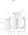
- FIG. 4 is a detailed perspective view of a blade 20 and a slide assembly 4 of the closure assembly according to the invention shown.
- the lamella 20 is formed in this embodiment so that it has hollow chambers 21, 22.
- the hollow chamber 21 of the lamella 20 is arranged in this embodiment by a partition wall 23 spaced from the hollow chamber 22.
- the lamella 20 further has at its one free end a hinge element 26 and at the hinge element 26 opposite the free end a receiving element 27th
- the lamella 20 is thus mounted on the insertion of the joint member 26 into the receiving element 27 of an adjacent lamella 20 to a closure element 2 of the closure assembly according to the invention.
- the lamella 20 is further designed such that it has a sliding arrangement 4 at its one free end.
- the sliding arrangement 4 has a sliding element 5 and a holding device 6.
- the slide assembly 4 is further formed so that the holding device 6 has a receiving space 60 in which the fixing device 7 is arranged.
- the holding device 6 of the slide assembly 4 is further configured so that in the receiving space 60, a locking element 16, 17 is arranged.
- the holding device 6 of the slide assembly 4 is formed so that they each have a first holding member 61 and a second holding member 62, which are arranged spaced apart from each other by the receiving space 60.
- the fixing device 7 of the slide assembly 4 is formed so that it has fixing elements 71, 72.
- the fixing device 7 of the slide assembly 4 is formed so that it has two, oppositely arranged fixing elements 71, 72. Furthermore, the fixing device 7 of the slide assembly 4 is formed so that it has two, spaced apart, fixing elements 71, 72.
- the sliding assembly 4 is further formed so that it has a, arranged on the holding device 6, stop element 9.
- the sliding element 5 is arranged at a distance from the stop element 9 of the sliding arrangement 4 via a spacer element 8.
- the stop element 9 serves to close the hollow chamber 21, 22.
- the slide assembly 4 of the closure assembly according to the invention is formed so that the fixing device 7 abuts against the locking element 16, 17.
- the spacer 9 of the slide assembly 4 is spaced from the free end of the blade 20.
- the fixing device 7 of the slide assembly 4 is further formed so that it has at least one opening 73, 74.
- the opening 73, 74 is arranged directly next to the fixing element 71, 72.
- the blade 20 is shown with the slide assembly 4 arranged thereon in the pre-assembled state.
- the fixing device 7 is arranged longitudinally displaceable in the receiving space 60 of the holding device 6 in this embodiment.
- the fixing device 7 When introducing the holding device 6 of the slide assembly 4 in the hollow chamber 21, 22 of the blade 20, the fixing device 7 sits on the partition wall 23 of the blade 20 and by the introduction of the holding elements 61, 62 of the slide assembly 4 in the hollow chamber 21, 22 of the blade 20th are the locking element 16, 17 of the holding device 6 with the opening 73, 74 of the fixing device 7 in operative connection.
- the sliding assembly 4 of the closure assembly according to the invention is thus positively fixed in the hollow chamber 21, 22 of the blade 20, since the fixing elements 71, 72 do not press reversibly into the partition wall 23 of the blade 20.
- the fixing device 7 of the slide assembly 4 of the closure assembly according to the invention is formed of a harder material than the lamella 20th
- the fixing device 7 is made of a metal such as steel, stainless steel, cast iron and the like.
- the slide assembly 4 is made in this embodiment in one piece from a polymeric material, namely polyoxymethylene (POM).
- the closure arrangement according to the invention for an opening is designed such that at least one free end of a lamella 20, a sliding assembly 4 is arranged, which is arranged on the arranged in the receiving space 60 fixing 7 form fit at least one wall of the hollow chamber 21, 22 of the blade 20.
- the fixing device 7 has further fixing elements, depending on the length or weight of the individual slats.
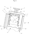
- FIG. 5 is a detailed perspective view of a blade 20 and a slide assembly 4 of the closure assembly according to the invention shown.
- the lamella 20 has a hollow chamber 21 in this embodiment.
- the lamella 20 is further formed in this embodiment, that it has on its one longitudinal side a joint member 26 and on its opposite longitudinal side a receiving element 27.
- the hinge elements 26 are longitudinally displaceably inserted into the adjacently arranged receiving elements 27 of further slats 20 so that a closure element 2 of the closure arrangement according to the invention can be mounted.
- the sliding assembly 4 is arranged in this embodiment, which has a sliding member 5 and a holding device 6.
- the holding device 6 of the slide assembly 4 is at least partially disposed in the hollow chamber 21 of the blade 20 in this embodiment.
- the slide assembly 4 of the closure assembly according to the invention is further designed so that the holding device 6 has a receiving space 60 in which the fixing device 7 is arranged.
- the fixing device 7 of the slide assembly 4 is designed so that it is longitudinally movable in the receiving space 60 of the holding device 6.
- the fixing device 7 of the slide assembly 4 is further formed so that it has a fixing element 71, 72.
- the fixing device 7 of the slide assembly 4 is formed so that it has two, spaced apart, fixing elements 71, 72.
- the sliding assembly 4 is arranged in this embodiment in the hollow chamber 21 of the blade 20, that the fixing device 7 abuts each of the joint member 26 and the receiving elements 27 opposite wall of the hollow chamber 21.
- the fixing device further has an opening 73, which is arranged on the locking element 16 of the holding device 6 of the slide assembly 4.
- the locking element 16 is positioned in the receiving space 60 of the holding device 6.
- the sliding assembly 4 is further formed so that it has a, arranged on the holding device 6, stop element 9.
- the stop element 9 covers the opening of the hollow chamber 21 of the lamella 20.
- the slide assembly 4 is at least partially disposed in the hollow chamber 21 in the preassembled state at the free end of the blade 20 in this embodiment.
- the sliding device 4 For the intended use of the closure arrangement according to the invention for an opening, it is now necessary to position the sliding device 4 completely longitudinally displaceable in the hollow chamber 21 of the lamella 20. In this position, the locking element 16 of the holding device 6 is in operative connection with the opening 73 of the fixing device 7.
- the fixing device 7 is connected via the fixing elements 71, 72 with the wall of the blade 20 in operative connection, so that the sliding assembly 4 is arranged or positioned positively in the hollow chamber 21 of the blade 20.
- closure assembly it is now possible to close or open an opening of a cupboard, a shower cubicle, a building and the like with at least one closure element 2, without the attachment or the leadership of the closure element 2 in the non Guide devices 3, 3 'shown for the viewer is visible.
- the closure arrangement according to the invention which can be produced economically and inexpensively, thus has a visually appealing overall impression both from its outside and from its inside, without the fixing elements known from the prior art being visible.
Landscapes
- Engineering & Computer Science (AREA)
- Structural Engineering (AREA)
- Architecture (AREA)
- Civil Engineering (AREA)
- Operating, Guiding And Securing Of Roll- Type Closing Members (AREA)
Abstract
Description
- Die Erfindung betrifft eine Verschlussanordnung für eine Öffnung, insbesondere eines Schrankmöbels, einer Duschkabine, eines Gebäudes und dergleichen, mit wenigstens einem Verschlusselement, insbesondere Jalousie, Rollladen und dergleichen, welches im Bereich der Öffnung von einer geschlossenen Position (GP) in eine offene Position (OP) und zurück bewegbar angeordnet ist, das parallel zueinander angeordnete Lamellen aufweist, wobei wenigstens eine Lamelle wenigstens eine Hohlkammer und an wenigstens einem freien Ende wenigstens eine Gleitanordnung aufweist, mit wenigstens einer an der Öffnung des Bauteils angeordneten Führungsvorrichtung.
- Derartige Verschlussanordnungen für Öffnungen sind im Stand der Technik beschrieben. So beschreibt beispielsweise die
DE 2 936 245 A1 eine Verschlussanordnung für eine Öffnung, insbesondere eines Schrankmöbels, mit wenigstens einem Verschlusselement, wobei das Verschlusselement jeweils aus einer Vielzahl von Glasstreifen besteht, die faltbar, d.h. gelenkig, miteinander verbunden sind, die eine als Verschiebeführung der Glastüren dienende Schiene auf zumindest dem Boden des Schrankmöbels angeordnet und vom vorderen Teil zu den Seitenwänden des Schrankkörbers erstreckt ist und das die Glasstreifen ein auf ihren rückwärtigen Oberflächen geklebtes flexibles Band miteinander verbunden sind. Das Verschlusselement ist weiterhin so ausgebildet, dass an beiden freien Enden der Lamellen jeweils Gleitanordnungen angebracht sind, die über beispielsweise Rollen und / oder zylindrische Zapfen in den Führungsschienen von einer geschlossen Position in eine offene Position und zurück bewegbar angeordnet sind. - Nachteilig bei dieser Verschlussanordnung ist der hohe Material- und insbesondere Montageaufwand in der Erstellung insbesondere des Verschlusselementes.
- Weiterhin nachteilig bei der Verschlussanordnung aus dem Stand der Technik ist, dass das Verschlusselement so aufgebaut ist, dass sie nur an ihrer Außenseite einen optisch ansprechenden Gesamteindruck aufweist.
- Die Verschlussanordnung aus dem Stand der Technik weist weiterhin noch den Nachteil auf, dass das Verschlusselement in den Führungsvorrichtungen nur sehr schwer, d.h. mit einem erhöhten Kraftaufwand von einer geschlossenen Position in eine offene Position und zurück bewegbar ist.
Nachteilig bei diesen Verschlussanordnungen ist einerseits deren kostenintensive und aufwendige Herstellung bzw. Konfektion sowie andererseits deren nicht optimaler optischer Eindruck bei bestimmungsgemäßer Verwendung, insbesondere bei Schrankmöbeln, Duschkabinen, Gebäuden und dergleichen. - Ein weiterer Nachteil bei den Verschlussanordnungen im Stand der Technik besteht darin, dass diese beistimmungsgemäßer Verwendung insbesondere bei großen Schrankmöbeln, Duschkabinen, Gebäuden und dergleichen das Verschlusselement ein hohes Gewicht aufweist, welches insbesondere durch die an den freien Enden der Lamellen angeordneten Gleitanordnungen und der am Bauteil angeordneten Führungsvorrichtung zum einen bewegt werden müssen, zum anderen auch statisch ausreichend dimensioniert sein müssen. Dies setzt bei den Verschlussanordnungen für Bauteile aus dem Stand der Technik weitere zusätzliche sicherheitsrelevante Bauteile sowie zusätzliche aufwendige Montage- und Konfektionsarbeiten nach sich, sodass diese Verschlussanordnungen für Bauteile sehr preisintensiv sind.
- Weiterhin nachteilig ist es gerade bei diesen Verschlussanordnungen für Bauteile, dass die zusätzlichen sicherheitsrelevanten Teile dann auch im Sichtbereich erkennbar und so den optischen Gesamteindruck dieser Verschlussanordnung negativ beeinflussen.
- Hier setzt die Erfindung ein, die sich die Aufgabe gestellt hat, eine Verschlussanordnung für eine Öffnung, insbesondere eines Schrankmöbels, einer Duschkabine, eines Gebäudes und dergleichen aufzuzeigen, die die Nachteile des bekannten Standes der Technik überwindet, die wirtschaftlich und kostengünstig herstellbar ist, deren Montage bzw. Konfektion schnell, reversibel und werkzeuglos möglich ist und die bei bestimmungsgemäßer Verwendung sowohl von der Außenseite als auch von der Innenseite einen optisch ansprechenden Gesamteindruck aufweist; sowie ein Schrankmöbel, eine Duschkabine, ein Gebäude und dergleichen.
- Erfindungsgemäß wird diese Aufgabe durch die Merkmale des Anspruches 1 sowie des Anspruches 14 gelöst.
- Es konnte überraschend festgestellt werden, dass eine Verschlussanordnung für eine Öffnung, insbesondere eines Schrankmöbels, einer Duschkabine, eines Gebäudes und dergleichen, mit wenigstens einem Verschlusselement, insbesondere Jalousie, Rollladen und dergleichen, welches im Bereich einer Öffnung des Bauteils von einer geschlossenen Position in eine offene Position und zurück bewegbar angeordnet ist, das parallel zueinander angeordnete Lamellen aufweist, wobei wenigstens eine Lamelle wenigstens eine Hohlkammer und an wenigstens einem freien Ende wenigstens eine Gleitanordnung aufweist, mit wenigstens einer an der Öffnung des Bauteils angeordneten Führungsvorrichtung sich dadurch auszeichnet, dass die Gleitanordnung wenigstens ein Gleitelement sowie eine Haltevorrichtung aufweist, das die Haltevorrichtung wenigstens einen Aufnahmeraum, in dem wenigstens eine Fixiervorrichtung anordenbar ist, aufweist und das die Fixiervorrichtung wenigstens ein Fixierelement aufweist. Diese erfindungsgemäße Verschlussanordnung für Bauteile ist überraschenderweise so ausgebildet, dass die Gleitanordnung über die Haltevorrichtung sowie die Fixiervorrichtung insbesondere werkzeuglos in der Hohlkammer einer Lamelle anordenbar sowie fixierbar ist, sodass an den Außenseiten der Lamelle des Verschlusselements der erfindungsgemäßen Verschlussanordnung keinerlei sichtbare Befestigungsteile erkennbar sind. Es konnte bei der erfindungsgemäßen Verschlussanordnung für Bauteile weiterhin festgestellt werden, dass durch eine geschickte Dimensionierung der im Aufnahmeraum der Haltevorrichtung angeordneten Fixiervorrichtung die Gleitanordnung nicht kraftschlüssig sondern insbesondere formschlüssig am freien Ende der Lamelle fixierbar ist.
- In einer weiteren vorteilhaften Ausgestaltung der erfindungsgemäßen Verschlussanordnung steht die Haltevorrichtung mit wenigstens einem freien Ende wenigstens einer Lamelle in Wirkverbindung. Dabei weist die Haltevorrichtung der erfindungsgemäßen Verschlussanordnung eine äquivalente Außengeometrie zu der Innengeometrie des freien Endes der Lamelle auf, sodass hierdurch schon vorteilhafterweise eine kraftschlüssige Wirkverbindung realisierbar ist.
- Es hat sich weiterhin als vorteilhaft herausgestellt, dass die Haltevorrichtung in wenigstens einer Hohlkammer einer Lamelle angeordnet ist. Hierdurch ist überraschenderweise erreichbar, dass die Halte- und Fixierfunktion insbesondere der Gleitanordnung im nicht sichtbaren Bereich des Verschlusselementes erfolgt, sodass das Verschlusselement der erfindungsgemäßen Verschlussanordnung für Bauteile auch einen optisch ansprechenden Gesamteindruck aufweist.
- In einer weiteren vorteilhaften Ausgestaltung der erfindungsgemäßen Verschlussanordnung ist die Fixiervorrichtung in wenigstens einem Aufnahmeraum der Haltevorrichtung angeordnet. In dieser vorteilhaften Ausgestaltung der erfindungsgemäßen Verschlussanordnung erfolgt die Fixierung der Gleitanordnung im nicht sichtbaren Bereich in einer Hohlkammer einer Lamelle.
- Es hat sich weiterhin als äußerst vorteilhaft herausgestellt bei der erfindungsgemäßen Verschlussanordnung, dass die Fixiervorrichtung in wenigstens einem Aufnahmeraum der Haltevorrichtung längsverschieblich angeordnet ist. Dies führt vorteilhafterweise zu einer wirtschaftlichen und kostengünstigen Herstellung insbesondere der Gleitanordnung für die erfindungsgemäße Verschlussanordnung und auch zu einer einfachen Montage am freien Ende der Lamelle des Verschlusselementes.
- Ein weiterer Vorteil der erfindungsgemäßen Verschlussanordnung besteht darin, dass die Fixiervorrichtung über wenigstens ein Fixierelement mit wenigstens einer Wand der Lamelle in Wirkverbindung steht. Hierdurch ist es erstmals überraschenderweise möglich, eine Gleitanordnung werkzeuglos und formschlüssig am freien Ende einer Lamelle zu positionieren und insbesondere zu fixieren.
- In einer ebenfalls vorteilhaften Ausgestaltung der erfindungsgemäßen Verschlussanordnung ist im Aufnahmeraum der Haltevorrichtung wenigstens ein Arretierungselement angeordnet. Die erfindungsgemäße Verschlussanordnung ist dabei vorteilhafterweise so ausgebildet, dass die im Aufnahmeraum der Haltevorrichtung längsverschieblich angeordnete Fixiervorrichtung von einer ersten Position in eine zweite Position längsverschieblich bewegbar ist, in der die Fixiervorrichtung an den Arretierungselementen im Aufnahmeraum der Haltevorrichtung fixiert ist.
- Weiterhin vorteilhaft bei der erfindungsgemäßen Verschlussanordnung ist, dass die Fixiervorrichtung wenigstens eine Öffnung aufweist. Dies führt vorteilhafterweise zu einer wirtschaftlichen und kostengünstigen Herstellung.
- Ein weiterer Vorteil der erfindungsgemäßen Verschlussanordnung besteht darin, dass das Arretierungselement der Haltevorrichtung mit der Öffnung der Fixiervorrichtung in Wirkverbindung steht. Bei der erfindungsgemäße Verschlussanordnung wurde erkannt, dass bei der Herstellung der Gleitanordnung mit der im Aufnahmeraum der Haltevorrichtung angeordneten Fixiervorrichtung eine schnelle Montage durch Positionierung der Gleitvorrichtung am freien Ende der Lamelle möglich ist und das durch Hineinpressen der Gleitvorrichtung in die Hohlkammer am freien Ende der Lamelle die Fixiervorrichtung von ihrer ersten Position in ihre zweite Position längsverschieblich bewegbar ist, in der sie über ihre Öffnungen an den Arretierungselementen der Haltevorrichtung der Gleitanordnung fixiert und gleichzeitig auch die Lamelle des Verschlusselementes fixiert ist.
- Ebenfalls vorteilhaft bei der erfindungsgemäßen Verschlussanordnung ist, dass die Haltevorrichtung ein erstes Halteelement sowie ein zweites Halteelement aufweist, die durch den Aufnahmeraum voneinander beabstandet angeordnet sind. In dieser vorteilhaften Ausgestaltung der erfindungsgemäßen Verschlussanordnung kann die Gleitanordnung insbesondere in die Hohlkammer von Lamellen einführbar sein, die durch eine separate Trennwand voneinander beabstandet angeordnet sind. Hierdurch ist eine wirtschaftliche und kostengünstige Herstellung insbesondere der Verschlusselemente mit den Gleitanordnungen möglich, wobei gleichzeitig eine nicht sichtbare, formschlüssige Fixierung der Gleitanordnung in der Hohlkammer der Lamelle realisierbar ist.
- Es hat sich weiterhin als vorteilhaft herausgestellt bei der erfindungsgemäßen Verschlussanordnung, dass die Gleitanordnung wenigstens ein, an der Haltevorrichtung angeordnetes Anschlagelement aufweist. In dieser vorteilhaften Ausgestaltung der erfindungsgemäßen Verschlussanordnung ist eine schnelle, sichere sowie optimale Positionierung und Fixierung der Gleitanordnung an den freien Enden der Lamelle problemlos möglich.
- Ebenfalls vorteilhaft bei der erfindungsgemäßen Verschlussanordnung ist, dass das Gleitelement der Gleitanordnung über ein Distanzelement vom Anschlagelement der Gleitanordnung beabstandet angeordnet ist. Durch diese vorteilhafte Ausgestaltung können erfindungsgemäße Verschlussanordnungen für Bauteile zur Verfügung gestellt werden, die sowohl in neue Schrankmöbel, Duschen, Gebäude und deren Führungsvorrichtung einführbar sind als auch als Ersatz für bereits bestehende Verschlussanordnung in Bauteilen. Weiterhin kann durch die Dimensionierung, die Werkstoffauswahl sowie das Design der Gleitanordnung insgesamt auch Rücksicht auf die Gewichte bzw. Abmessungen aller Verschlusselemente einer Verschlussanordnung für Bauteile genommen werden.
- In einer weiteren vorteilhaften Ausgestaltung der Verschlussanordnung besteht die Gleitanordnung wenigstens teilweise aus einem polymeren Werkstoff, ausgewählt aus der Gruppe wie Polyvinylchlorid (PVC); Polyolefin, wie Polypropylen (PP) oder Polyethylen (PE); styrolbasiertes Polymer, wie Polystyrol (PS) oder Styrol-Butadien-Copolymer mit überwiegendem Styrolanteil (SB) oder Acrylnitril-Styrol-Acrylester-Copolymere (ASA) oder AcrylnitrilButadien-Styrol-Copolymere (ABS) oder Styrolacrylnitril (SAN); Polybutylentherephthalat (PBT); Polyethylentherephthalat (PET); Polyoxymethylen (POM); Polyamid (PA); Polymethylmethacrylat (PMMA); Polyphenylenoxid (PPO); Polyetheretherketon (PEEK); Polyphenylensulfid (PPS); Liquid Crystal Polymer (LCP); Polyamidimide (PAI); Polyvinylidenfluorid (PVDF); Polyphenylsulfon (PPSU); Polyaryletherketon (PAEK); Polyacrylnitril (PAN); Polychlortrifluorethylen (PCTFE); Polyetherketon (PEK); Polyimid (PI); Polyisobuten (PIB); Polyphthalamid (PPA); Polypyrrol PPY); Polytetrafluorethylen (PTFE); Polyurethan (PUR); Polyvinylalkohol (PVA); Polyvinylacetat (PVAC); Polyvinylidenchlorid (PVDC); sowie Mischungen aus wenigstens zwei dieser Materialien.
- Es hat sich weiterhin als vorteilhaft herausgestellt, dass die Fixiervorrichtung wenigstens zwei, einander gegenüberliegend angeordnete, Fixierelemente aufweist. Ebenfalls vorteilhaft bei der erfindungsgemäßen Verschlussanordnung ist es, dass die Fixiervorrichtung wenigstens zwei, voneinander beanstandet, angeordnete Fixierelemente aufweist. Durch diese vorteilhafte Ausgestaltung der erfindungsgemäßen Verschlussanordnung kann die jeweilige Fixiervorrichtung so dimensioniert und positioniert werden, dass bei den derzeit bekannten Lamellen von Verschlusselementen jederzeit eine einfache Positionierung, Montage sowie Fixierung an wenigstens einer Wand der Hohlkammer der Lamelle werkzeuglos realisierbar ist.
- Die Erfindung betrifft weiterhin ein Schrankmöbel, eine Duschkabine, ein Gebäude und dergleichen mit wenigstens einer Verschlussanordnung gemäß den vorherigen Ausführungen.
- Die Erfindung soll nun an diesen nicht einschränkenden Ausführungsbeispielen näher beschrieben werden.
- Es zeigen:
- Fig. 1:
- perspektivische Darstellung einer erfindungsgemäßen Verschlussanordnung für die Öffnung eines Schrankmöbels;
- Fig. 2:
- Vorderansicht einer erfindungsgemäßen Verschlussanordnung für die Öffnung einer Duschkabine;
- Fig. 3:
- Vorderansicht einer erfindungsgemäßen Verschlussanordnung;
- Fig. 4:
- perspektivische Detaildarstellung einer Lamelle sowie einer Gleitanordnung der erfindungsgemäßen Verschlussanordnung;
- Fig. 5:
- perspektivische Detaildarstellung einer Lamelle sowie einer Gleitanordnung der erfindungsgemäßen Verschlussanordnung.
- In der
Fig. 1 ist eine perspektivische Darstellung einer erfindungsgemäßen Verschlussanordnung für die Öffnung 10 eines Schrankmöbels 100 dargestellt. - Der Schrankmöbel 100 umfasst einen, die Öffnung 10 aufweisenden, Möbelkorpus 16 sowie ein Verschlusselement 2 auf.
Der Möbelkorpus 16 ist in diesem Ausführungsbeispiel so ausgebildet, dass er eine Seitenwand 11, eine dieser gegenüberliegend angeordnete Seitenwand 12, einen Boden 13 sowie einen diesem gegenüberliegend angeordneten Oberboden 14 aufweist.
An der, der Öffnung 10 des Schrankmöbels 100 gegenüberliegenden, Seite des Möbelkorpus 16 ist eine Rückwand 15 angeordnet. - Das Verschlusselement 2, insbesondere Jalousie, Rollladen und dergleichen, weist parallel zueinander angeordnete Lamellen 20 auf und ist in, an der Öffnung 10 des Möbelkorpus 16 angeordneten, Führungsvorrichtungen 3, 3' geführt.
Die Lamellen 20 des Verschlusselements 2 sind in diesem Ausführungsbeispiel so ausgebildet, dass sie an ihren Stirnseiten jeweils eine, hier nicht sichtbare, Gleitanordnung aufweisen.
In diesem Ausführungsbeispiel weist die erfindungsgemäße Verschlussanordnung an ihrem einem freien Ende eine Griffelement 25 auf, mit dem das Verschlusselement 2 in den Führungsvorrichtungen 3, 3' bewegbar ist von einer geschlossenen Position (GP) in eine offene Position (OP). - In der
Fig. 2 ist eine Vorderansicht einer erfindungsgemäßen Verschlussanordnung für die Öffnung 10 einer Duschkabine 110 dargestellt. - Die Duschkabine 110 ist so ausgebildet, dass sie eine Seitenwand 11, eine ihr gegenüberliegend angeordnete Seitenwand 12 sowie einen Oberboden 14 aufweist.
- Die Duschkabine 110 ist in diesem Ausführungsbeispiel weiter so ausgeführt, dass das Verschlusselement 2 in der geschlossenen Position (GP) dargestellt ist, sodass die Öffnung 10 verschlossen und somit nicht sichtbar ist.
- Das Verschlusselement 2, insbesondere Jalousie, Rollladen und dergleichen weist parallel zueinander angeordnete Lamellen 20 auf und ist in an der Öffnung der Duschkabine 110 angeordneten Führungselementen 3, 3' geführt.
In diesem Ausführungsbeispiel sind die Lamellen 20 des Verschlusselementes 2 vertikal zueinander angeordnet und werden in horizontal dazu angeordneten Führungsvorrichtungen 3, 3' geführt.
Die Lamellen 20 des Verschlusselementes 2 sind in diesem Ausführungsbeispiel so ausgebildet, dass sie an ihren Stirnseiten jeweils eine, hier nicht sichtbare, in der Führungsvorrichtung 3, 3' führbare Gleitanordnung aufweisen. - In diesem Ausführungsbeispiel weist die erfindungsgemäße Verschlussanordnung an ihrem einen freien Ende, welches der Seitenwand 12 der Duschkabine 110 gegenüberliegend angeordnet ist, ein Griffelement 25 auf, mit dem das Verschlusselement 2 bei bestimmungsgemäßer Verwendung in den Führungsvorrichtungen 3, 3' von der hier dargestellten geschlossenen Positionen (GP) in eine offene Position (OP) und zurück bewegbar angeordnet ist.
- In der
Fig. 3 ist eine Vorderansicht einer erfindungsgemäßen Verschlussanordnung für eine Öffnung dargestellt. - Die Verschlussanordnung umfasst ein Verschlusselement 2, insbesondere Jalousie, Rollladen und dergleichen welches im Bereich einer Öffnung von einer geschlossenen Position (GP) in eine offene Position (OP) und zurück bewegbar angeordnet ist, das parallel zueinander angeordnete Lamellen 20 aufweist, wobei wenigstens eine Lamelle 20 wenigstens eine Hohlkammer 21 und an wenigstens einem freien Ende wenigstens eine Gleitanordnung 4 aufweist.
- In diesem Ausführungsbeispiel ist das Verschlusselement 2 der erfindungsgemäßen Verschlussanordnung so dargestellt, dass eine erste Lamelle 20 in einer Teilschnittdarstellung die in der Hohlkammer 21 angeordnete Gleitanordnung 4 zeigt.
Die Lamelle 20 des Verschlusselementes 2 ist in diesem Ausführungsbeispiel so ausgebildet, dass die Hohlkammer 21 über eine Trennwand 23 von einer weiteren Hohlkammer 22 beabstandet angeordnet ist. - Weiterhin ist das Verschlusselement 2 der erfindungsgemäßen Verschlussanordnung in diesem Ausführungsbeispiel so ausgebildet, dass an jedem freien Ende jeder Lamelle 20 jeweils eine Gleitanordnung 4 in einer Hohlkammer 21, 22 angeordnet ist.
Es liegt jedoch auch im Rahmen der Erfindung, dass das Verschlusselement 2 so ausgebildet ist, dass nur an einem freien Ende jeder Lamelle 20, beispielsweise oben, jeweils eine Gleitanordnung 4 in wenigstens einer Hohlkammer 21,22 angeordnet ist.
Es liegt weiterhin im Rahmen der Erfindung, dass das Verschlusselement 2 so ausgebildet ist, dass an einem freien Ende jeder Lamelle 20 jeweils eine Gleitanordnung 4 alternierend oben und unten versetzt, in wenigstens einer Hohlkammer 21,22 angeordnet ist. - Das Verschlusselement 2 der erfindungsgemäßen Verschlussanordnung ist so ausgebildet, dass es wie in diesem Ausführungsbeispiel beschrieben in horizontal angeordneten Führungsvorrichtungen, die hier nicht dargestellt sind, bewegbar ist.
Es liegt jedoch auch im Rahmen der Erfindung, dass die Verschlussanordnung horizontal zueinander angeordnete Lamellen 20 des Verschlusselementes 2 aufweist und so in vertikal angeordneten Führungsvorrichtungen 3, 3', welche hier nicht dargestellt sind, bewegbar ist. - In der
Fig. 4 ist eine perspektivische Detaildarstellung einer Lamelle 20 sowie einer Gleitanordnung 4 der erfindungsgemäßen Verschlussanordnung dargestellt. - Die Lamelle 20 ist in diesem Ausführungsbeispiel so ausgebildet, dass sie Hohlkammern 21, 22 aufweist.
Die Hohlkammer 21 der Lamelle 20 ist in diesem Ausführungsbeispiel durch eine Trennwand 23 von der Hohlkammer 22 beabstandet angeordnet.
Die Lamelle 20 weist weiterhin an ihrem einen freien Ende ein Gelenkelement 26 auf und an dem dem Gelenkelement 26 gegenüberliegend angeordneten freien Ende ein Aufnahmeelement 27. - Die Lamelle 20 wird somit über das Ineinandereinfügen des Gelenkelements 26 in das Aufnahmeelement 27 einer benachbarten Lamelle 20 zu einem Verschlusselement 2 der erfindungsgemäßen Verschlussanordnung montiert.
- Die Lamelle 20 ist weiterhin so ausgebildet, dass sie an ihrem einen freien Ende eine Gleitanordnung 4 aufweist.
Die Gleitanordnung 4 weist ein Gleitelement 5 sowie eine Haltevorrichtung 6 auf. - Die Gleitanordnung 4 ist weiterhin so ausgebildet, dass die Haltevorrichtung 6 einen Aufnahmeraum 60 aufweist, in dem die Fixiervorrichtung 7 angeordnet ist.
Die Haltevorrichtung 6 der Gleitanordnung 4 ist weiterhin so ausgebildet, dass im Aufnahmeraum 60 ein Arretierungselement 16, 17 angeordnet ist.
In diesem Ausführungsbeispiel ist die Haltevorrichtung 6 der Gleitanordnung 4 so ausgebildet, dass sie jeweils ein erstes Halteelement 61 sowie ein zweites Halteelement 62 aufweist, die durch den Aufnahmeraum 60 voneinander beabstandet angeordnet sind. - Die Fixiervorrichtung 7 der Gleitanordnung 4 ist so ausgebildet, dass sie Fixierelemente 71, 72 aufweist.
In diesem Ausführungsbeispiel ist die Fixiervorrichtung 7 der Gleitanordnung 4 so ausgebildet, dass sie zwei, einander gegenüberliegend angeordnete Fixierelemente 71, 72 aufweist. Weiterhin ist die Fixiervorrichtung 7 der Gleitanordnung 4 so ausgebildet, dass sie zwei, voneinander beabstandet angeordnete, Fixierelemente 71, 72 aufweist. - Die Gleitanordnung 4 ist weiterhin so ausgebildet, dass sie ein, an der Haltevorrichtung 6 angeordnetes, Anschlagelement 9 aufweist.
In diesem Ausführungsbeispiel ist das Gleitelement 5 über ein Distanzelement 8 vom Anschlagelement 9 der Gleitanordnung 4 beabstandet angeordnet. - Bei bestimmungsgemäßem Einsatz der Gleitanordnung 4 an einem freien Ende wenigstens einer Lamelle 20 dient das Anschlagelement 9 dazu, die Hohlkammer 21, 22 zu verschließen.
- In diesem Ausführungsbeispiel ist die Gleitanordnung 4 der erfindungsgemäßen Verschlussanordnung so ausgebildet, dass die Fixiervorrichtung 7 an dem Arretierungselement 16, 17 anliegt.
- Das Distanzelement 9 der Gleitanordnung 4 ist vom freien Ende der Lamelle 20 beabstandet angeordnet.
- Die Fixiervorrichtung 7 der Gleitanordnung 4 ist weiterhin so ausgebildet, dass sie wenigstens eine Öffnung 73, 74 aufweist. In diesem Ausführungsbeispiel ist die Öffnung 73,74 unmittelbar neben dem Fixierelement 71, 72 angeordnet.
- In dieser Darstellung ist die Lamelle 20 mit der daran angeordneten Gleitanordnung 4 im Vormontagezustand dargestellt.
- Um hierzu eine erfindungsgemäße Verschlussanordnung zu erhalten, ist es nun erforderlich, dass die Gleitanordnung 4 über die Halteelemente 61, 62 in die Hohlkammer 21, 22 der Lamelle 20 hinein zu bewegen, bis das Anschlagelement 9 direkt am freien Ende der Lamelle 20 anliegt.
- Die Fixiervorrichtung 7 ist in diesem Ausführungsbeispiel längsverschieblich im Aufnahmeraum 60 der Haltevorrichtung 6 angeordnet.
- Beim Einbringen der Haltevorrichtung 6 der Gleitanordnung 4 in die Hohlkammer 21, 22 der Lamelle 20 sitzt die Fixiervorrichtung 7 auf der Trennwand 23 der Lamelle 20 auf und durch das Einbringen der Halteelemente 61, 62 der Gleitanordnung 4 in die Hohlkammer 21, 22 der Lamelle 20 stehen das Arretierungselement 16, 17 der Haltevorrichtung 6 mit der Öffnung 73, 74 der Fixiervorrichtung 7 in Wirkverbindung.
Die Gleitanordnung 4 der erfindungsgemäßen Verschlussanordnung ist somit formschlüssig in der Hohlkammer 21, 22 der Lamelle 20 fixiert, da die Fixierelemente 71, 72 sich nicht reversibel in die Trennwand 23 der Lamelle 20 einpressen. - Die Fixiervorrichtung 7 der Gleitanordnung 4 der erfindungsgemäßen Verschlussanordnung ist dabei aus einem härteren Werkstoff ausgebildet als die Lamelle 20.
In diesem Ausführungsbeispiel ist die Fixiervorrichtung 7 aus einem Metall, wie Stahl, Edelstahl, Gusseisen und dergleichen hergestellt.
Die Gleitanordnung 4 ist in diesem Ausführungsbeispiel einstückig aus einem polymeren Werkstoff hergestellt, nämlich aus Polyoxymethylen (POM). - Die erfindungsgemäße Verschlussanordnung für eine Öffnung ist so ausgebildet, dass an wenigstens einem freien Ende wenigstes einer Lamelle 20 eine Gleitanordnung 4 angeordnet ist, die über die im Aufnahmeraum 60 angeordnete Fixiervorrichtung 7 formschlüssig wenigstens einer Wand der Hohlkammer 21, 22 der Lamelle 20 angeordnet ist.
- Es liegt auch im Rahmen der Erfindung, dass die Fixiervorrichtung 7 weitere Fixierelemente aufweist, je nach der Länge bzw. dem Gewicht der einzelnen Lamellen.
- In der
Fig. 5 ist eine perspektivische Detaildarstellung einer Lamelle 20 sowie einer Gleitanordnung 4 der erfindungsgemäßen Verschlussanordnung dargestellt. - Die Lamelle 20 weist in diesem Ausführungsbeispiel eine Hohlkammer 21 auf.
Die Lamelle 20 ist in diesem Ausführungsbeispiel weiterhin so ausgebildet, dass sie an ihrer einen Längsseite ein Gelenkelement 26 sowie an ihrer gegenüberliegenden Längsseite ein Aufnahmeelement 27 aufweist.
Bei bestimmungsgemäßem Einsatz der Lamelle 20 zur Montage eines Verschlusselementes 2 für die erfindungsgemäße Verschlussanordnung werden die Gelenkelemente 26 in die benachbart angeordneten Aufnahmeelemente 27 weiterer Lamelle 20 längsverschieblich eingeführt, sodass ein Verschlusselement 2 der erfindungsgemäßen Verschlussanordnung montierbar ist. - Am freien Ende der Lamelle 20 ist in diesem Ausführungsbeispiel die Gleitanordnung 4 angeordnet, welche ein Gleitelement 5 sowie eine Haltevorrichtung 6 aufweist.
Die Haltevorrichtung 6 der Gleitanordnung 4 ist in diesem Ausführungsbeispiel zumindest teilweise in der Hohlkammer 21 der Lamelle 20 angeordnet.
Die Gleitanordnung 4 der erfindungsgemäßen Verschlussanordnung ist weiterhin so ausgebildet, dass die Haltevorrichtung 6 einen Aufnahmeraum 60 aufweist, in dem die Fixiervorrichtung 7 angeordnet ist.
Die Fixiervorrichtung 7 der Gleitanordnung 4 ist dabei so ausgebildet, dass sie in dem Aufnahmeraum 60 der Haltevorrichtung 6 längsverschieblich bewegbar ist.
Die Fixiervorrichtung 7 der Gleitanordnung 4 ist weiterhin so ausgebildet, dass sie ein Fixierelement 71, 72 aufweist.
In diesem Ausführungsbeispiel weist die Fixiervorrichtung 7 zwei, einander gegenüberliegend angeordnete Fixierelemente 71, 72 auf. Weiterhin ist die Fixiervorrichtung 7 der Gleitanordnung 4 so ausgebildet, dass sie zwei, voneinander beabstandet angeordnete, Fixierelemente 71, 72 aufweist. - Die Gleitanordnung 4 ist in diesem Ausführungsbeispiel so in der Hohlkammer 21 der Lamelle 20 angeordnet, dass die Fixiervorrichtung 7 jeweils an der dem Gelenkelement 26 und dem Aufnahmeelemente 27 gegenüberliegend angeordneten Wand der Hohlkammer 21 anliegt.
- Die Fixiervorrichtung weist weiterhin eine Öffnung 73 auf, die an dem Arretierungselement 16 der Haltevorrichtung 6 der Gleitanordnung 4 angeordnet ist.
- Das Arretierungselement 16 ist dabei im Aufnahmeraum 60 der Haltevorrichtung 6 positioniert.
- Die Gleitanordnung 4 ist weiterhin so ausgebildet, dass sie ein, an der Haltevorrichtung 6 angeordnetes, Anschlagelement 9 aufweist.
Bei bestimmungsgemäßer Verwendung der Gleitanordnung 4 in der Lamelle 20 der erfindungsgemäßen Verschlussanordnung verdeckt das Anschlagelement 9 die Öffnung der Hohlkammer 21 der Lamelle 20.
Bei bestimmungsgemäßer Verwendung der Lamelle 20 mit der darin angeordneten Gleitanordnung 4 ist das Gleitelement 5 in der nicht dargestellten Führungsvorrichtung 3, 3' geführt und gehalten. - Die Gleitanordnung 4 ist in diesem Ausführungsbeispiel im vormontierten Zustand am freien Ende der Lamelle 20 zumindest teilweise in der Hohlkammer 21 angeordnet.
- Zur bestimmungsgemäßen Verwendung der erfindungsgemäßen Verschlussanordnung für eine Öffnung ist es nun erforderlich, die Gleitvorrichtung 4 vollständig längsverschieblich in der Hohlkammer 21 der Lamelle 20 zu positionieren.
In dieser Position steht das Arretierungselement 16 der Haltevorrichtung 6 mit der Öffnung 73 der Fixiervorrichtung 7 in Wirkverbindung.
Die Fixiervorrichtung 7 steht dabei über die Fixierelemente 71, 72 mit der Wand der Lamelle 20 in Wirkverbindung, sodass die Gleitanordnung 4 formschlüssig in der Hohlkammer 21 der Lamelle 20 angeordnet bzw. positioniert ist. - In dieser vorteilhaften Ausgestaltung der erfindungsgemäßen Verschlussanordnung ist es erstmals möglich, eine Öffnung eines Schrankmöbels, einer Duschkabine, eines Gebäudes und dergleichen mit wenigstens einem Verschlusselement 2 zu verschließen bzw. zu öffnen, ohne das die Befestigung bzw. die Führung des Verschlusselements 2 in den nicht dargestellten Führungsvorrichtungen 3, 3' für den Betrachter ersichtlich ist.
- Die erfindungsgemäße Verschlussanordnung, welche wirtschaftlich und kostengünstig herstellbar ist, weist somit sowohl von ihrer Außenseite als auch von ihrer Innenseite einen optisch ansprechenden Gesamteindruck auf, ohne das aus dem Stand der Technik bekannte Fixierelemente sichtbar sind.
Claims (14)
- Verschlussanordnung für eine Öffnung (10), insbesondere eines Schrankmöbel, einer Duschkabine, eines Gebäude und dergleichen, mit wenigstens einem Verschlusselement (2), insbesondere Jalousie, Rollladen und dergleichen, welches im Bereich der Öffnung (10) von einer geschlossenen Position (GP) in eine offene Position (OP) und zurück bewegbar angeordnet ist, das parallel zueinander angeordnete Lamellen (20) aufweist, wobei wenigstens eine Lamelle (20) wenigstens eine Hohlkammer (21) und an wenigstens einem freien Enden wenigstens eine Gleitanordnung (4) aufweist, mit wenigstens einer an der Öffnung (10) des Bauteils (1) angeordneten Führungsvorrichtung (3, 3'), dadurch gekennzeichnet, dass die Gleitanordnung (4) wenigstens ein Gleitelement (5) sowie eine Haltevorrichtung (6) aufweist, dass die Haltevorrichtung (6) wenigstens einen Aufnahmeraum (60), in dem wenigstens eine Fixiervorrichtung (7) anordenbar ist, aufweist und dass die Fixiervorrichtung (7) wenigstens ein Fixierelement (71, 72) aufweist.
- Verschlussanordnung nach Anspruch 1, dadurch gekennzeichnet, dass die Haltevorrichtung (6) mit wenigstens einem freien Ende wenigstens einer Lamelle (20) in Wirkverbindung steht.
- Verschlussanordnung nach einem der vorhergehenden Ansprüche, dadurch gekennzeichnet, dass die Haltevorrichtung (6) in wenigstens einer Hohlkammer (21) wenigstens einer Lamelle (20) angeordnet ist.
- Verschlussanordnung nach einem der vorhergehenden Ansprüche, dadurch gekennzeichnet, dass die Fixiervorrichtung (7) in wenigstens einem Aufnahmeraum (60) der Haltevorrichtung (6) längsverschieblich angeordnet ist.
- Verschlussanordnung nach einem der vorhergehenden Ansprüche, dadurch gekennzeichnet, dass die Fixiervorrichtung (7) über wenigstens ein Fixierelement (71, 72) mit wenigstens einer Wand der Lamelle (20) in Wirkverbindung steht.
- Verschlussanordnung nach einem der vorhergehenden Ansprüche, dadurch gekennzeichnet, dass im Aufnahmeraum (60) der Haltevorrichtung (6) wenigstens ein Arretierungselement (16,17) angeordnet ist.
- Verschlussanordnung nach einem der vorhergehenden Ansprüche, dadurch gekennzeichnet, dass die Fixiervorrichtung (7) wenigstens eine Öffnung (73,74) aufweist.
- Verschlussanordnung nach einem der vorhergehenden Ansprüche, dadurch gekennzeichnet, dass das Arretierungselement (16,17) der Haltevorrichtung (6) mit der Öffnung (73, 74) der Fixiervorrichtung (7) in Wirkverbindung steht.
- Verschlussanordnung nach einem der vorhergehenden Ansprüche, dadurch gekennzeichnet, dass die Haltevorrichtung (6) ein erstes Halteelement (61) sowie ein zweites Halteelement (62) aufweist, die durch den Aufnahmeraum (60) voneinander beanstandet angeordnet sind.
- Verschlussanordnung nach einem der vorhergehenden Ansprüche, dadurch gekennzeichnet, dass die die Gleitanordnung (4) wenigstens ein, an der Haltevorrichtung (6) angeordnetes, Anschlagelement (9) aufweist.
- Verschlussanordnung nach einem der vorhergehenden Ansprüche, dadurch gekennzeichnet, dass das Gleitelement (5) über ein Distanzelement (8) vom Anschlagelement (9) der Gleitanordnung (4) beanstandet angeordnet ist.
- Verschlussanordnung nach einem der vorhergehenden Ansprüche, dadurch gekennzeichnet, dass die Fixiervorrichtung (7) wenigstens zwei, einander gegenüberliegend angeordnete, Fixierelemente (71, 72) aufweist.
- Verschlussanordnung nach einem der vorhergehenden Ansprüche, dadurch gekennzeichnet, dass die Fixiervorrichtung (6) wenigstens zwei, voneinander beanstandet angeordnete, Fixierelemente (71, 72) aufweist.
- Schrankmöbel, Duschkabine, Gebäude und dergleichen, mit wenigstens einer Verschlussanordnung nach einem der Ansprüche 1 bis 13.
Applications Claiming Priority (1)
| Application Number | Priority Date | Filing Date | Title |
|---|---|---|---|
| DE202016107162.3U DE202016107162U1 (de) | 2016-12-20 | 2016-12-20 | Verschlussanordnung für Bauteile |
Publications (2)
| Publication Number | Publication Date |
|---|---|
| EP3339556A1 true EP3339556A1 (de) | 2018-06-27 |
| EP3339556B1 EP3339556B1 (de) | 2022-02-02 |
Family
ID=60673786
Family Applications (1)
| Application Number | Title | Priority Date | Filing Date |
|---|---|---|---|
| EP17207926.1A Active EP3339556B1 (de) | 2016-12-20 | 2017-12-18 | Verschlussanordnung für gebäudebauteile |
Country Status (2)
| Country | Link |
|---|---|
| EP (1) | EP3339556B1 (de) |
| DE (1) | DE202016107162U1 (de) |
Citations (6)
| Publication number | Priority date | Publication date | Assignee | Title |
|---|---|---|---|---|
| DE2936245A1 (de) | 1978-09-08 | 1980-03-20 | Matsushita Electric Ind Co Ltd | Vitrine mit glastueren |
| EP0170338A1 (de) * | 1984-07-26 | 1986-02-05 | Assenburg B.V. | Rolltor, Rolladen o.d. |
| DE29611369U1 (de) * | 1996-06-29 | 1996-09-05 | Beckhoff Alulux Gmbh & Co | In seitlichen Führungsschienen geführter Rolladen |
| DE20308668U1 (de) * | 2002-05-24 | 2003-08-28 | Hörmann KG Dissen, 49201 Dissen | Endstück für ein Glied eines mehrgliedrigen Gebäudeabschlussflügels sowie damit versehener Gebäudeabschluss |
| FR2918100A1 (fr) * | 2007-06-27 | 2009-01-02 | Rehau Sa | Embout antivibratoire pour lames de tablier de volets roulants, de portes coulissantes ou analogues. |
| DE102012020658A1 (de) * | 2012-10-20 | 2014-04-24 | Vkt Velten Kunststofftechnik Gmbh | Einsteckelement für Rollläden und Rollladen, umfassend dieses Einsteckelement |
-
2016
- 2016-12-20 DE DE202016107162.3U patent/DE202016107162U1/de not_active Expired - Lifetime
-
2017
- 2017-12-18 EP EP17207926.1A patent/EP3339556B1/de active Active
Patent Citations (6)
| Publication number | Priority date | Publication date | Assignee | Title |
|---|---|---|---|---|
| DE2936245A1 (de) | 1978-09-08 | 1980-03-20 | Matsushita Electric Ind Co Ltd | Vitrine mit glastueren |
| EP0170338A1 (de) * | 1984-07-26 | 1986-02-05 | Assenburg B.V. | Rolltor, Rolladen o.d. |
| DE29611369U1 (de) * | 1996-06-29 | 1996-09-05 | Beckhoff Alulux Gmbh & Co | In seitlichen Führungsschienen geführter Rolladen |
| DE20308668U1 (de) * | 2002-05-24 | 2003-08-28 | Hörmann KG Dissen, 49201 Dissen | Endstück für ein Glied eines mehrgliedrigen Gebäudeabschlussflügels sowie damit versehener Gebäudeabschluss |
| FR2918100A1 (fr) * | 2007-06-27 | 2009-01-02 | Rehau Sa | Embout antivibratoire pour lames de tablier de volets roulants, de portes coulissantes ou analogues. |
| DE102012020658A1 (de) * | 2012-10-20 | 2014-04-24 | Vkt Velten Kunststofftechnik Gmbh | Einsteckelement für Rollläden und Rollladen, umfassend dieses Einsteckelement |
Also Published As
| Publication number | Publication date |
|---|---|
| DE202016107162U1 (de) | 2018-03-22 |
| EP3339556B1 (de) | 2022-02-02 |
Similar Documents
| Publication | Publication Date | Title |
|---|---|---|
| WO2015051892A1 (de) | Verschlussanordnung | |
| EP3369609B1 (de) | Stromschienensystem | |
| DE202012000898U1 (de) | Eckverbindungsbeschlag | |
| EP3835525B1 (de) | Schiebetürbeschlag und zugehörige schiebetüranordnung | |
| DE202012102510U1 (de) | Eckverbindungselement | |
| EP1926113B1 (de) | Schaltelement für motorisch bewegte Türen, Tore oder dgl. und Montageverfahren hierzu | |
| EP3339556B1 (de) | Verschlussanordnung für gebäudebauteile | |
| DE19828186A1 (de) | Gelenkeinrichtung, insbesondere für Rolladen- oder Falttürelemente, und Roll- oder Faltvorhang | |
| DE202010018232U1 (de) | Rollladenkasten | |
| EP2639907B1 (de) | Verbindungsanordnung für Kabelkanalelemente | |
| EP3099881A1 (de) | Verschlussanordnung | |
| EP2735690B1 (de) | Rollladenkasten | |
| DE102018111616A1 (de) | Verschlussanordnung insbesondere für Schrankmöbel | |
| DE202005016773U1 (de) | Vorrichtung zum lösbaren Halten einer Verschlußeinheit | |
| DE102014001609B4 (de) | Möbeljalousie | |
| EP2994591B1 (de) | Verschlussanordnung | |
| EP2639906B1 (de) | Verbindungsanordnung für Kabelkanalsysteme | |
| DE202016100638U1 (de) | Verschlussanordnung insbesondere für Schrankmöbel | |
| DE202012102136U1 (de) | Z-förmige Geräteeinbaukanal-Übergangsstückanordnung | |
| EP2994592B1 (de) | Schrankmöbel | |
| EP2076646B1 (de) | Führungsanordnung | |
| DE102016118705B4 (de) | Verschlussanordnung | |
| DE102017125570A1 (de) | Verschlussanordnung, insbesondere für Schrankmöbel | |
| DE2159244B2 (de) | Eckumlenkung für Triebstangenbeschläge | |
| CH700838B1 (de) | Führungselement für eine Rolltür. |
Legal Events
| Date | Code | Title | Description |
|---|---|---|---|
| PUAI | Public reference made under article 153(3) epc to a published international application that has entered the european phase |
Free format text: ORIGINAL CODE: 0009012 |
|
| STAA | Information on the status of an ep patent application or granted ep patent |
Free format text: STATUS: THE APPLICATION HAS BEEN PUBLISHED |
|
| AK | Designated contracting states |
Kind code of ref document: A1 Designated state(s): AL AT BE BG CH CY CZ DE DK EE ES FI FR GB GR HR HU IE IS IT LI LT LU LV MC MK MT NL NO PL PT RO RS SE SI SK SM TR |
|
| AX | Request for extension of the european patent |
Extension state: BA ME |
|
| STAA | Information on the status of an ep patent application or granted ep patent |
Free format text: STATUS: REQUEST FOR EXAMINATION WAS MADE |
|
| 17P | Request for examination filed |
Effective date: 20181218 |
|
| RBV | Designated contracting states (corrected) |
Designated state(s): AL AT BE BG CH CY CZ DE DK EE ES FI FR GB GR HR HU IE IS IT LI LT LU LV MC MK MT NL NO PL PT RO RS SE SI SK SM TR |
|
| RAP1 | Party data changed (applicant data changed or rights of an application transferred) |
Owner name: REHAU AG + CO |
|
| GRAP | Despatch of communication of intention to grant a patent |
Free format text: ORIGINAL CODE: EPIDOSNIGR1 |
|
| STAA | Information on the status of an ep patent application or granted ep patent |
Free format text: STATUS: GRANT OF PATENT IS INTENDED |
|
| INTG | Intention to grant announced |
Effective date: 20210813 |
|
| GRAS | Grant fee paid |
Free format text: ORIGINAL CODE: EPIDOSNIGR3 |
|
| GRAA | (expected) grant |
Free format text: ORIGINAL CODE: 0009210 |
|
| STAA | Information on the status of an ep patent application or granted ep patent |
Free format text: STATUS: THE PATENT HAS BEEN GRANTED |
|
| AK | Designated contracting states |
Kind code of ref document: B1 Designated state(s): AL AT BE BG CH CY CZ DE DK EE ES FI FR GB GR HR HU IE IS IT LI LT LU LV MC MK MT NL NO PL PT RO RS SE SI SK SM TR |
|
| REG | Reference to a national code |
Ref country code: GB Ref legal event code: FG4D Free format text: NOT ENGLISH |
|
| REG | Reference to a national code |
Ref country code: CH Ref legal event code: EP Ref country code: AT Ref legal event code: REF Ref document number: 1466639 Country of ref document: AT Kind code of ref document: T Effective date: 20220215 |
|
| REG | Reference to a national code |
Ref country code: DE Ref legal event code: R096 Ref document number: 502017012552 Country of ref document: DE |
|
| REG | Reference to a national code |
Ref country code: IE Ref legal event code: FG4D Free format text: LANGUAGE OF EP DOCUMENT: GERMAN |
|
| RAP2 | Party data changed (patent owner data changed or rights of a patent transferred) |
Owner name: REHAU INDUSTRIES SE & CO. KG |
|
| REG | Reference to a national code |
Ref country code: LT Ref legal event code: MG9D |
|
| REG | Reference to a national code |
Ref country code: GB Ref legal event code: 732E Free format text: REGISTERED BETWEEN 20220505 AND 20220512 |
|
| REG | Reference to a national code |
Ref country code: NL Ref legal event code: MP Effective date: 20220202 |
|
| PG25 | Lapsed in a contracting state [announced via postgrant information from national office to epo] |
Ref country code: SE Free format text: LAPSE BECAUSE OF FAILURE TO SUBMIT A TRANSLATION OF THE DESCRIPTION OR TO PAY THE FEE WITHIN THE PRESCRIBED TIME-LIMIT Effective date: 20220202 Ref country code: RS Free format text: LAPSE BECAUSE OF FAILURE TO SUBMIT A TRANSLATION OF THE DESCRIPTION OR TO PAY THE FEE WITHIN THE PRESCRIBED TIME-LIMIT Effective date: 20220202 Ref country code: PT Free format text: LAPSE BECAUSE OF FAILURE TO SUBMIT A TRANSLATION OF THE DESCRIPTION OR TO PAY THE FEE WITHIN THE PRESCRIBED TIME-LIMIT Effective date: 20220602 Ref country code: NO Free format text: LAPSE BECAUSE OF FAILURE TO SUBMIT A TRANSLATION OF THE DESCRIPTION OR TO PAY THE FEE WITHIN THE PRESCRIBED TIME-LIMIT Effective date: 20220502 Ref country code: NL Free format text: LAPSE BECAUSE OF FAILURE TO SUBMIT A TRANSLATION OF THE DESCRIPTION OR TO PAY THE FEE WITHIN THE PRESCRIBED TIME-LIMIT Effective date: 20220202 Ref country code: LT Free format text: LAPSE BECAUSE OF FAILURE TO SUBMIT A TRANSLATION OF THE DESCRIPTION OR TO PAY THE FEE WITHIN THE PRESCRIBED TIME-LIMIT Effective date: 20220202 Ref country code: HR Free format text: LAPSE BECAUSE OF FAILURE TO SUBMIT A TRANSLATION OF THE DESCRIPTION OR TO PAY THE FEE WITHIN THE PRESCRIBED TIME-LIMIT Effective date: 20220202 Ref country code: ES Free format text: LAPSE BECAUSE OF FAILURE TO SUBMIT A TRANSLATION OF THE DESCRIPTION OR TO PAY THE FEE WITHIN THE PRESCRIBED TIME-LIMIT Effective date: 20220202 Ref country code: BG Free format text: LAPSE BECAUSE OF FAILURE TO SUBMIT A TRANSLATION OF THE DESCRIPTION OR TO PAY THE FEE WITHIN THE PRESCRIBED TIME-LIMIT Effective date: 20220502 |
|
| PG25 | Lapsed in a contracting state [announced via postgrant information from national office to epo] |
Ref country code: PL Free format text: LAPSE BECAUSE OF FAILURE TO SUBMIT A TRANSLATION OF THE DESCRIPTION OR TO PAY THE FEE WITHIN THE PRESCRIBED TIME-LIMIT Effective date: 20220202 Ref country code: LV Free format text: LAPSE BECAUSE OF FAILURE TO SUBMIT A TRANSLATION OF THE DESCRIPTION OR TO PAY THE FEE WITHIN THE PRESCRIBED TIME-LIMIT Effective date: 20220202 Ref country code: GR Free format text: LAPSE BECAUSE OF FAILURE TO SUBMIT A TRANSLATION OF THE DESCRIPTION OR TO PAY THE FEE WITHIN THE PRESCRIBED TIME-LIMIT Effective date: 20220503 Ref country code: FI Free format text: LAPSE BECAUSE OF FAILURE TO SUBMIT A TRANSLATION OF THE DESCRIPTION OR TO PAY THE FEE WITHIN THE PRESCRIBED TIME-LIMIT Effective date: 20220202 |
|
| REG | Reference to a national code |
Ref country code: DE Ref legal event code: R081 Ref document number: 502017012552 Country of ref document: DE Owner name: REHAU INDUSTRIES SE & CO. KG, DE Free format text: FORMER OWNER: REHAU AG + CO, 95111 REHAU, DE |
|
| RAP4 | Party data changed (patent owner data changed or rights of a patent transferred) |
Owner name: REHAU INDUSTRIES SE & CO. KG |
|
| PG25 | Lapsed in a contracting state [announced via postgrant information from national office to epo] |
Ref country code: IS Free format text: LAPSE BECAUSE OF FAILURE TO SUBMIT A TRANSLATION OF THE DESCRIPTION OR TO PAY THE FEE WITHIN THE PRESCRIBED TIME-LIMIT Effective date: 20220602 |
|
| PG25 | Lapsed in a contracting state [announced via postgrant information from national office to epo] |
Ref country code: SM Free format text: LAPSE BECAUSE OF FAILURE TO SUBMIT A TRANSLATION OF THE DESCRIPTION OR TO PAY THE FEE WITHIN THE PRESCRIBED TIME-LIMIT Effective date: 20220202 Ref country code: SK Free format text: LAPSE BECAUSE OF FAILURE TO SUBMIT A TRANSLATION OF THE DESCRIPTION OR TO PAY THE FEE WITHIN THE PRESCRIBED TIME-LIMIT Effective date: 20220202 Ref country code: RO Free format text: LAPSE BECAUSE OF FAILURE TO SUBMIT A TRANSLATION OF THE DESCRIPTION OR TO PAY THE FEE WITHIN THE PRESCRIBED TIME-LIMIT Effective date: 20220202 Ref country code: EE Free format text: LAPSE BECAUSE OF FAILURE TO SUBMIT A TRANSLATION OF THE DESCRIPTION OR TO PAY THE FEE WITHIN THE PRESCRIBED TIME-LIMIT Effective date: 20220202 Ref country code: DK Free format text: LAPSE BECAUSE OF FAILURE TO SUBMIT A TRANSLATION OF THE DESCRIPTION OR TO PAY THE FEE WITHIN THE PRESCRIBED TIME-LIMIT Effective date: 20220202 Ref country code: CZ Free format text: LAPSE BECAUSE OF FAILURE TO SUBMIT A TRANSLATION OF THE DESCRIPTION OR TO PAY THE FEE WITHIN THE PRESCRIBED TIME-LIMIT Effective date: 20220202 |
|
| REG | Reference to a national code |
Ref country code: DE Ref legal event code: R097 Ref document number: 502017012552 Country of ref document: DE |
|
| PG25 | Lapsed in a contracting state [announced via postgrant information from national office to epo] |
Ref country code: AL Free format text: LAPSE BECAUSE OF FAILURE TO SUBMIT A TRANSLATION OF THE DESCRIPTION OR TO PAY THE FEE WITHIN THE PRESCRIBED TIME-LIMIT Effective date: 20220202 |
|
| PLBE | No opposition filed within time limit |
Free format text: ORIGINAL CODE: 0009261 |
|
| STAA | Information on the status of an ep patent application or granted ep patent |
Free format text: STATUS: NO OPPOSITION FILED WITHIN TIME LIMIT |
|
| 26N | No opposition filed |
Effective date: 20221103 |
|
| PG25 | Lapsed in a contracting state [announced via postgrant information from national office to epo] |
Ref country code: SI Free format text: LAPSE BECAUSE OF FAILURE TO SUBMIT A TRANSLATION OF THE DESCRIPTION OR TO PAY THE FEE WITHIN THE PRESCRIBED TIME-LIMIT Effective date: 20220202 |
|
| REG | Reference to a national code |
Ref country code: AT Ref legal event code: PC Ref document number: 1466639 Country of ref document: AT Kind code of ref document: T Owner name: REHAU INDUSTRIES SE & CO. KG, DE Effective date: 20230427 |
|
| REG | Reference to a national code |
Ref country code: BE Ref legal event code: PD Owner name: REHAU INDUSTRIES SE & CO. KG; DE Free format text: DETAILS ASSIGNMENT: CHANGE OF OWNER(S), ASSIGNMENT; FORMER OWNER NAME: REHAU INDUSTRIES SE & CO. KG Effective date: 20230828 |
|
| PG25 | Lapsed in a contracting state [announced via postgrant information from national office to epo] |
Ref country code: HU Free format text: LAPSE BECAUSE OF FAILURE TO SUBMIT A TRANSLATION OF THE DESCRIPTION OR TO PAY THE FEE WITHIN THE PRESCRIBED TIME-LIMIT; INVALID AB INITIO Effective date: 20171218 |
|
| PG25 | Lapsed in a contracting state [announced via postgrant information from national office to epo] |
Ref country code: CY Free format text: LAPSE BECAUSE OF FAILURE TO SUBMIT A TRANSLATION OF THE DESCRIPTION OR TO PAY THE FEE WITHIN THE PRESCRIBED TIME-LIMIT Effective date: 20220202 |
|
| PG25 | Lapsed in a contracting state [announced via postgrant information from national office to epo] |
Ref country code: MK Free format text: LAPSE BECAUSE OF FAILURE TO SUBMIT A TRANSLATION OF THE DESCRIPTION OR TO PAY THE FEE WITHIN THE PRESCRIBED TIME-LIMIT Effective date: 20220202 |
|
| PG25 | Lapsed in a contracting state [announced via postgrant information from national office to epo] |
Ref country code: MC Free format text: LAPSE BECAUSE OF FAILURE TO SUBMIT A TRANSLATION OF THE DESCRIPTION OR TO PAY THE FEE WITHIN THE PRESCRIBED TIME-LIMIT Effective date: 20220202 |
|
| PG25 | Lapsed in a contracting state [announced via postgrant information from national office to epo] |
Ref country code: MC Free format text: LAPSE BECAUSE OF FAILURE TO SUBMIT A TRANSLATION OF THE DESCRIPTION OR TO PAY THE FEE WITHIN THE PRESCRIBED TIME-LIMIT Effective date: 20220202 |
|
| PG25 | Lapsed in a contracting state [announced via postgrant information from national office to epo] |
Ref country code: MT Free format text: LAPSE BECAUSE OF FAILURE TO SUBMIT A TRANSLATION OF THE DESCRIPTION OR TO PAY THE FEE WITHIN THE PRESCRIBED TIME-LIMIT Effective date: 20220202 |
|
| PGFP | Annual fee paid to national office [announced via postgrant information from national office to epo] |
Ref country code: LU Payment date: 20241126 Year of fee payment: 8 |
|
| PGFP | Annual fee paid to national office [announced via postgrant information from national office to epo] |
Ref country code: BE Payment date: 20241125 Year of fee payment: 8 |
|
| PGFP | Annual fee paid to national office [announced via postgrant information from national office to epo] |
Ref country code: GB Payment date: 20241202 Year of fee payment: 8 |
|
| PGFP | Annual fee paid to national office [announced via postgrant information from national office to epo] |
Ref country code: AT Payment date: 20241125 Year of fee payment: 8 |
|
| PGFP | Annual fee paid to national office [announced via postgrant information from national office to epo] |
Ref country code: IE Payment date: 20241126 Year of fee payment: 8 |
|
| PGFP | Annual fee paid to national office [announced via postgrant information from national office to epo] |
Ref country code: CH Payment date: 20250101 Year of fee payment: 8 |
|
| PG25 | Lapsed in a contracting state [announced via postgrant information from national office to epo] |
Ref country code: TR Free format text: LAPSE BECAUSE OF FAILURE TO SUBMIT A TRANSLATION OF THE DESCRIPTION OR TO PAY THE FEE WITHIN THE PRESCRIBED TIME-LIMIT Effective date: 20220202 |
|
| PGFP | Annual fee paid to national office [announced via postgrant information from national office to epo] |
Ref country code: IT Payment date: 20251230 Year of fee payment: 9 |
|
| PGFP | Annual fee paid to national office [announced via postgrant information from national office to epo] |
Ref country code: FR Payment date: 20251125 Year of fee payment: 9 |
|
| PGFP | Annual fee paid to national office [announced via postgrant information from national office to epo] |
Ref country code: DE Payment date: 20251231 Year of fee payment: 9 |
|
| REG | Reference to a national code |
Ref country code: CH Ref legal event code: H13 Free format text: ST27 STATUS EVENT CODE: U-0-0-H10-H13 (AS PROVIDED BY THE NATIONAL OFFICE) Effective date: 20260723 |