EP3339104B1 - Stromtransporteinrichtung, insbesondere elektrische oder elektromechanische stromschiene - Google Patents
Stromtransporteinrichtung, insbesondere elektrische oder elektromechanische stromschiene Download PDFInfo
- Publication number
- EP3339104B1 EP3339104B1 EP17207212.6A EP17207212A EP3339104B1 EP 3339104 B1 EP3339104 B1 EP 3339104B1 EP 17207212 A EP17207212 A EP 17207212A EP 3339104 B1 EP3339104 B1 EP 3339104B1
- Authority
- EP
- European Patent Office
- Prior art keywords
- plug
- conductor
- transport mechanism
- connection device
- current transport
- Prior art date
- Legal status (The legal status is an assumption and is not a legal conclusion. Google has not performed a legal analysis and makes no representation as to the accuracy of the status listed.)
- Active
Links
Images



Classifications
-
- H—ELECTRICITY
- H01—ELECTRIC ELEMENTS
- H01R—ELECTRICALLY-CONDUCTIVE CONNECTIONS; STRUCTURAL ASSOCIATIONS OF A PLURALITY OF MUTUALLY-INSULATED ELECTRICAL CONNECTING ELEMENTS; COUPLING DEVICES; CURRENT COLLECTORS
- H01R25/00—Coupling parts adapted for simultaneous co-operation with two or more identical counterparts, e.g. for distributing energy to two or more circuits
- H01R25/16—Rails or bus-bars provided with a plurality of discrete connecting locations for counterparts
-
- B—PERFORMING OPERATIONS; TRANSPORTING
- B60—VEHICLES IN GENERAL
- B60L—PROPULSION OF ELECTRICALLY-PROPELLED VEHICLES; SUPPLYING ELECTRIC POWER FOR AUXILIARY EQUIPMENT OF ELECTRICALLY-PROPELLED VEHICLES; ELECTRODYNAMIC BRAKE SYSTEMS FOR VEHICLES IN GENERAL; MAGNETIC SUSPENSION OR LEVITATION FOR VEHICLES; MONITORING OPERATING VARIABLES OF ELECTRICALLY-PROPELLED VEHICLES; ELECTRIC SAFETY DEVICES FOR ELECTRICALLY-PROPELLED VEHICLES
- B60L5/00—Current collectors for power supply lines of electrically-propelled vehicles
- B60L5/38—Current collectors for power supply lines of electrically-propelled vehicles for collecting current from conductor rails
-
- B—PERFORMING OPERATIONS; TRANSPORTING
- B60—VEHICLES IN GENERAL
- B60L—PROPULSION OF ELECTRICALLY-PROPELLED VEHICLES; SUPPLYING ELECTRIC POWER FOR AUXILIARY EQUIPMENT OF ELECTRICALLY-PROPELLED VEHICLES; ELECTRODYNAMIC BRAKE SYSTEMS FOR VEHICLES IN GENERAL; MAGNETIC SUSPENSION OR LEVITATION FOR VEHICLES; MONITORING OPERATING VARIABLES OF ELECTRICALLY-PROPELLED VEHICLES; ELECTRIC SAFETY DEVICES FOR ELECTRICALLY-PROPELLED VEHICLES
- B60L5/00—Current collectors for power supply lines of electrically-propelled vehicles
- B60L5/42—Current collectors for power supply lines of electrically-propelled vehicles for collecting current from individual contact pieces connected to the power supply line
-
- B—PERFORMING OPERATIONS; TRANSPORTING
- B60—VEHICLES IN GENERAL
- B60R—VEHICLES, VEHICLE FITTINGS, OR VEHICLE PARTS, NOT OTHERWISE PROVIDED FOR
- B60R16/00—Electric or fluid circuits specially adapted for vehicles and not otherwise provided for; Arrangement of elements of electric or fluid circuits specially adapted for vehicles and not otherwise provided for
- B60R16/02—Electric or fluid circuits specially adapted for vehicles and not otherwise provided for; Arrangement of elements of electric or fluid circuits specially adapted for vehicles and not otherwise provided for electric constitutive elements
- B60R16/0207—Wire harnesses
- B60R16/0215—Protecting, fastening and routing means therefor
-
- H—ELECTRICITY
- H01—ELECTRIC ELEMENTS
- H01R—ELECTRICALLY-CONDUCTIVE CONNECTIONS; STRUCTURAL ASSOCIATIONS OF A PLURALITY OF MUTUALLY-INSULATED ELECTRICAL CONNECTING ELEMENTS; COUPLING DEVICES; CURRENT COLLECTORS
- H01R3/00—Electrically-conductive connections not otherwise provided for
-
- H—ELECTRICITY
- H02—GENERATION; CONVERSION OR DISTRIBUTION OF ELECTRIC POWER
- H02B—BOARDS, SUBSTATIONS OR SWITCHING ARRANGEMENTS FOR THE SUPPLY OR DISTRIBUTION OF ELECTRIC POWER
- H02B1/00—Frameworks, boards, panels, desks, casings; Details of substations or switching arrangements
- H02B1/20—Bus-bar or other wiring layouts, e.g. in cubicles, in switchyards
-
- H—ELECTRICITY
- H01—ELECTRIC ELEMENTS
- H01R—ELECTRICALLY-CONDUCTIVE CONNECTIONS; STRUCTURAL ASSOCIATIONS OF A PLURALITY OF MUTUALLY-INSULATED ELECTRICAL CONNECTING ELEMENTS; COUPLING DEVICES; CURRENT COLLECTORS
- H01R2201/00—Connectors or connections adapted for particular applications
- H01R2201/26—Connectors or connections adapted for particular applications for vehicles
-
- H—ELECTRICITY
- H01—ELECTRIC ELEMENTS
- H01R—ELECTRICALLY-CONDUCTIVE CONNECTIONS; STRUCTURAL ASSOCIATIONS OF A PLURALITY OF MUTUALLY-INSULATED ELECTRICAL CONNECTING ELEMENTS; COUPLING DEVICES; CURRENT COLLECTORS
- H01R25/00—Coupling parts adapted for simultaneous co-operation with two or more identical counterparts, e.g. for distributing energy to two or more circuits
- H01R25/16—Rails or bus-bars provided with a plurality of discrete connecting locations for counterparts
- H01R25/161—Details
-
- H—ELECTRICITY
- H01—ELECTRIC ELEMENTS
- H01R—ELECTRICALLY-CONDUCTIVE CONNECTIONS; STRUCTURAL ASSOCIATIONS OF A PLURALITY OF MUTUALLY-INSULATED ELECTRICAL CONNECTING ELEMENTS; COUPLING DEVICES; CURRENT COLLECTORS
- H01R4/00—Electrically-conductive connections between two or more conductive members in direct contact, i.e. touching one another; Means for effecting or maintaining such contact; Electrically-conductive connections having two or more spaced connecting locations for conductors and using contact members penetrating insulation
- H01R4/04—Electrically-conductive connections between two or more conductive members in direct contact, i.e. touching one another; Means for effecting or maintaining such contact; Electrically-conductive connections having two or more spaced connecting locations for conductors and using contact members penetrating insulation using electrically conductive adhesives
Definitions
- DE 10 2014 004 432 A1 teaches an electrical conduction device, in particular for a vehicle, which has an electrical main conductor and an electrical connection contact on the main conductor, the connection contact having an electrical connecting part made of a first material and a connecting piece made of a second material which is different from the first material.
- the connecting piece being joined to the connecting part in a materially joined manner by means of electromagnetic pulse technology, and the connecting piece being connected in a materially joined manner to the main conductor.
- the problem of the invention is solved by means of a vehicle current transport mechanism, in particular for a motor vehicle; by means of a current transport mechanism, in particular a current bar, a backbone or a bus bar for the automotive industry; and by means of an entity, a mechanism, a module, a subassembly, an appliance, an apparatus, a machine, a conveying means, a transport means, a system or a unit, according to the independent claims.
- 'rigidly mechanical' in 'electrically-rigidly mechanical' is intended to mean that the plug-in connection device itself, a connection between the plug-in connection device and the base conductor (in contrast to a hinge), and the mating plug-in connection device are formed mechanically stiffly or rigidly. This means that mechanical forces and/or torques can be transmitted between these in preferably three spatial dimensions.
- This of course also relates to the (electromechanical or electrically-rigidly mechanical) base conductor itself (in contrast to a flexible or three-dimensionally deflectable electrical conductor), however in a limited sense, which depends on its length, which enables a certain flexibility in a spatial dimension (where applicable, in sections) (see above).
- Formed or connected in one part is intended to mean that the plug-in connection device and the base conductor produce an interconnection, which cannot be mutually moved but which can be easily released by hand or by means of a tool (e.g. by means of deadlock, clipping, screwing, etc.), wherein, for example, a frictional engagement and/or positive engagement can be established between the two structural parts.
- a tool e.g. by means of deadlock, clipping, screwing, etc.
- one piece is intended to mean that the plug-in connection device and the base conductor further produce an interconnection, which can no longer be easily released by hand or by means of a tool, which can be the case with crimping, for example (damage to one or both structural parts when releasing the interconnection).
- a frictional engagement and, where applicable, a positive engagement is in this case obligatory.
- the current transport mechanism is formed materially/adhesively in one piece if the plug-in connection device is connected to the base conductor in a cohesive manner, where applicable to a frictional engagement and/or positive engagement, i.e. they often cannot be separated without damage. This is the case with an adhesion (in this case, a separation without damage may be possible), soldering (in this case, a separation without damage may also be possible), (spot) welding, etc.
- the current transport mechanism is formed simply if a connection between the plug-in connection device and the base conductor can no longer be separated without causing damage to or destroying both structural parts.
- the current transport mechanism is formed integrally if the plug-in connection device and the base conductor are formed substantially homogenous or made in/out of a single original piece.
- the base conductor can be formed substantially solidly and/or have an electrical insulation surrounding it in circumferential direction.
- the plug-in connection device can have a mechanical contact section, by means of which the plug-in connection device is fixed on the base conductor. Instead, the plug-in connection device can have a composite contact region, by means of which the plug-in connection device is formed with the base conductor. Furthermore, these plug-in connection devices can each have a plug-in contact section, which can be electrically and mechanically contacted by the mating plug-in connection device.
- the vehicle current transport mechanism can be formed and/or manufactured like a current transport mechanism, which is explained hereinafter.
- the inventive current transport mechanism has an elongated, electromechanical base conductor with an electrical insulation completely surrounding it in circumferential direction, the electrical insulation having at least one through-recess and the base conductor being electrically contacted by a plug-in connection device in a region of the through-recess, wherein the current transport mechanism has a jacket in a region of the plug-in connection device, and the jacket is formed in sections as a connector housing for a mating plug-in connection device, wherein the jacket is preferably formed as an overmould.
- the plug-in connection device can comprise a mechanical contact section and a plug-in contact section, the mechanical contact section electrically contacting the base conductor in the region of the through-recess and the plug-in contact section protruding from the base conductor.
- the jacket is preferably formed such that it seals the plug-in contact section of the plug-in connection device in a fluid-tight manner, in particular in a water-tight manner or water-vapour-tight manner, from the base conductor in the region of the through-recess.
- the jacket is formed in sections as a connector housing for a mating plug-in connection device. In this case, a housing of the mating plug-in connection device, if this is present, can be plugged into and/or onto the jacket.
- the base conductor can be formed as an electrically-rigidly mechanical base conductor.
- the plug-in connection device can be formed as a stamped part or a stamped bent part.
- the plug-in connection device can be formed as a tab contact device or a pin contact device.
- the plug-in connection device can be connected to the base conductor in one part, materially/adhesively in one piece or in one piece, wherein everything said above regarding one part and one piece also applies in this case.
- the base conductor can be contacted by the plug-in connection device in an electrically-rigidly mechanical manner in the region of the through-recess.
- the base conductor can be deoxidised in the region of the through-recess.
- the current transport mechanism can be formed like a vehicle current transport mechanism which is explained above and/or be manufactured like a current transport mechanism which is explained hereinafter.
- the current transport mechanism can be scaled as desired and manufactured in an automated manner.
- An interface plug-in connection device with a jacket
- a plurality or variety of current transport mechanisms on one single base conductor is easily realised.
- a method for manufacturing a current transport mechanism in particular a current bar, a backbone or a bus bar for the automotive industry, is explained in greater detail hereinafter.
- a first step an electrical insulation of an elongated, electromechanical base conductor is completely removed in a region of a plug-in connection device, which hereinafter should be provided on the base conductor, e.g. by cutting open and extracting the electrical insulation, and in a second step which follows the first step, the plug-in connection device is attached to the base conductor.
- the plug-in connection device can be separated from a carrier strip, e.g. on a reel. In such a way, a plurality of plug-in connection devices can of course be fixedly connected to the base conductor.
- a first step the electrical insulation is removed down to the base conductor, hence a through-recess is provided in the electrical insulation.
- the base conductor can be deoxidised in the region (through-recess) of the plug-in connection device, which hereinafter should be provided on the base conductor.
- the second step can take place, for example, by adhesion, soldering, welding, clinching etc.
- the plug-in connection device is fixed on the base conductor with a mechanical contact section which is formed thereon. A plug-in contact section of the plug-in connection device protrudes from the base conductor.
- the region of the plug-in connection device, which hereinafter should be provided on the base conductor must be initially identified, temporally before the first step.
- a jacket can be provided over the plug-in connection device, which is preferably moulded in.
- the jacket can completely encompass the base conductor and partially overlaps its electrical insulation or mechanically contacts it.
- the jacket seals off the plug-in contact section from the base conductor in a fluid-tight manner, in particular in a water-tight or water-vapour tight manner.
- the jacket can be formed in sections as a connector housing for a mating plug-in connection device. -
- the current transport mechanism obtained according to the invention can be formed as a vehicle current transport mechanism.
- the inventive current transport mechanism has an elongated, electromechanical conductor with an electrical insulation completely surrounding it in circumferential direction, the current transport mechanism having at least one plug-in connection device which is exposed out of the electrical insulation and the electromechanical conductor, wherein the electrical insulation is removed from the current transport mechanism in a region around the resulting plug-in connection device and a material of the electromechanical conductor is also removed.
- the plug-in connection device is exposed out of the electrical insulation and the electromechanical conductor of the current transport mechanism, in particular cut free and/or punched out.
- the electrical insulation is removed from the current transport mechanism in a region (optionally part of a predetermined contact region, see below) around the resulting plug-in connection device, and a material of the electromechanical conductor is also removed, depending on a shape and/or size of the resulting plug-in connection device, i.e. on two sides or on three sides around the resulting plug-in connection device.
- At least one slot arises laterally at the plug-in connection device (the plug-in connection device at a longitudinal end), but usually two slots arise (the plug-in connection device at the longitudinal centre section) opposite the remaining electromechanical conductor.
- the plug-in connection device is preferably embedded in the electromechanical conductor.
- the plug-in connection device is further provided in a plane of the electromechanical conductor, wherein it is connected on one side to the electromechanical conductor (preferably integrally or monolithically, see below) and is accessible at the side opposite thereto for the mating plug-in connection device.
- the current transport mechanism can have at least one predetermined contact region at an outer edge, out of which the plug-in connection device can be exposed.
- the electromechanical conductor in particular an electromechanical terminal conductor of the electromechanical conductor, can preferably be coated in the region of the predetermined contact region.
- the predetermined contact region can be outwardly marked on/in the electrical insulation of the current transport mechanism, e.g. by means of a box or the like.
- An established coating can have, for example, silver, tin, etc., the electromechanical conductor or the electromechanical terminal conductor preferably only being coated in a predetermined contact region.
- the electromechanical conductor of the current transport mechanism can be formed from a metallic composite product, in particular an aluminium/copper composite product.
- a metallic composite product in particular an aluminium/copper composite product.
- the advantage of copper is that it combines a comparatively high electrical conductivity with comparatively good electromechanical properties (plug-in connection, corrosion resistance, etc.); its high price and its comparatively high density (the heavy weight of an entity made of copper) are disadvantageous.
- the advantages of aluminium are its comparatively good electrical conductivity, its comparatively low density (the low weight of an entity made of aluminium) and its comparatively low price; its vulnerability to moisture is disadvantageous.
- aluminium is used in cases where a comparatively large amount of electrical current must be transported, such that a comparatively large amount of material is needed (costs), and corrosion plays a subordinate role (no or hardly any exposed aluminium).
- copper is used in cases where a comparatively small amount of material is needed (costs) and good electrical (contact) properties exist (current transport, mechanical resistance, where applicable corrosion resistance in the case of a partially exposed plug-in connection).
- the electromechanical conductor of the current transport mechanism can be formed from one single metallic product, in particular an aluminium product.
- the electromechanical conductor can comprise an elongated, electromechanical base conductor and an elongated, electromechanical terminal conductor which is arranged parallel thereto, the base conductor having a first metallic product, in particular an aluminium-based product, and the terminal conductor having a second metallic product, in particular a copper-based product, or the base conductor and the terminal conductor having the same metallic product and being formed integrally or monolithically with each other.
- Integral in turn means here that the base conductor and the terminal conductor are formed homogenous or made in/out of a single original piece. This also applies for a monolithic configuration, the base conductor and the terminal conductor being connected to each other via cohesion forces and the electromechanical conductor being formed of the base conductor and terminal conductor in a polycrystalline manner. In the latter case, a differentiation between the base conductor and the terminal conductor is only a notional line which cannot be observed at/in the electromechanical conductor.
- the terminal conductor can have substantially the same thickness as the base conductor. Furthermore, it is possible that the base conductor is formed thicker or thinner than the terminal conductor.
- the current transport mechanism can have at least one predetermined contact region at one or both longitudinal sides. Furthermore, the current transport mechanism can have a terminal conductor at one or both longitudinal sides, which terminal conductor extends along a longitudinal section of the base conductor, the terminal conductor preferably extending along an entire longitudinal extension of the base conductor.
- a thickness of the plug-in connection device or the terminal conductor can be smaller than, the same as or greater than a thickness of the base conductor.
- the current transport mechanism can be formed as a multilayer current transport mechanism with a plurality of electromechanical conductors, in particular as a bilayer current transport mechanism with two electromechanical conductors.
- the base conductor can be formed as an electrically-rigidly mechanical base conductor.
- the terminal conductor can be formed as an electrically-rigidly mechanical terminal conductor.
- the plug-in connection device can be formed as a tab contact device or a pin contact device.
- the plug-in connection device can be formed monolithically, integrally, simply or materially/adhesively in one piece with the base conductor.
- the current transport mechanism can be formed like a vehicle current transport mechanism which is explained above and/or be manufactured like a current transport mechanism which is explained hereinafter.
- the current transport mechanism can be scaled as desired and manufactured in an automated manner.
- a fluid-tight, in particular water-tight or water-vapour-tight, interface can be realised by a housing, e.g. with a seal, of a mating plug-in connection device.
- a plurality or variety of current transport mechanisms on one single base conductor is easily realised.
- the current transport mechanism preferably has, as above, an elongated, electromechanical conductor with an electrical insulation surrounding it in the circumferential direction.
- a position of a plug-in connection device, which should be formed therein is determined, and in a second step, which temporally follows the first step, the plug-in connection device is established in the blank of the current transport mechanism, whereby the actual current transport mechanism is obtained.
- the plug-in connection device can be formed as a tab contact device or a pin contact device.
- the plug-in connection device In the first step, a positioning of the plug-in connection device, which should be formed in the blank, is facilitated by a marked, (e.g. on/in the electrical insulation) predetermined contact region.
- the plug-in connection device is preferably exposed out of the electrical insulation of the blank and the electromechanical conductor, in particular cut free and/or punched out, which can take place successively or simultaneously. If this takes place successively, the electrical insulation is initially removed down to the electromechanical conductor, hence a through-recess is provided in the electrical insulation. Subsequently, the plug-in connection device is formed in the electromechanical conductor.
- the current transport mechanism or the blank of the current transport mechanism has at least one predetermined contact region at the outer edge, out of which the plug-in connection device is exposed.
- a plug-in contact section of the plug-in connection device protrudes from the electromechanical conductor, but is preferably established (embedded) therein inside a longitudinal side of the current transport mechanism.
- a first variant Figs. 1-5
- three exemplary embodiments Figs. 6-8 and Figs. 9 , 10, 12 , 14-16 and Figs. 11, 13
- a second variant of a (vehicle) current transport mechanism 1 such as an (energy/power) backbone 1, an (energy/power) bus bar 1.
- the invention is not limited to such variants, embodiments and/or the exemplary embodiments which are explained hereinafter, but is of a more fundamental nature, such that it can be applied to all current transport mechanisms in accordance with the invention, e.g. for an appliance 0, a machine 0, a conveying means 0, a system 0, a unit 0, etc., e.g. for a non-automotive industry.
- an elongated or rod-shaped electrical or electrically (-rigidly) mechanical base conductor 10 such as an actual (current) bar 10, preferably made of aluminium or an aluminium alloy, is surmised.
- the base conductor 10 has an electrical insulation 30, which preferably completely surrounds it in the circumferential direction and which in particular is made of a preferably moulded-in plastic.
- the two end faces of the base conductor 10 can also have the electrical insulation 30.
- the base conductor 10 is initially completely encapsulated or electrically insulated.
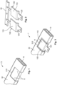
- a region is initially localised on the electrical insulation 30 of the base conductor 10, in which region an initially separate, electrical or electrically-rigidly mechanical plug-in connection device 100 ( Fig. 2 ) is intended to be fixedly provided or assembled on the base conductor 10 ( Fig. 1 ).
- the preferably integral one-piece or one-part plug-in connection device 100 is preferably formed as a (faston) tab contact device 100 or a pin contact device; a bushing contact device can of course also be used.
- the plug-in connection device 100 is preferably manufactured from aluminium or copper or an aluminium alloy or a copper alloy, in particular stamped or stamped and bent.
- the plug-in connection device 100 has a contact section 110 for assembling the plug-in connection device 100 on the base conductor 10 and a plug-in contact section 120, by means of which the plug-in connection device 100 can be electrically contacted by an electrical or electrically-rigidly mechanical mating plug-in connection device 9 (cf. Figs. 12, 13 , 16 ).
- the plug-in connection device 100 can be completely or selectively coated, e.g. with silver 222, tin 222, etc. In the case of a selective coating, only the plug-in contact section 120 is also, where applicable, selectively coated on one side or on two sides.
- the plug-in connection device 100 is preferably provided by a carrier strip 90, e.g. on a reel.
- the electrical insulation 30 is substantially completely removed from the base conductor 10 in this region (first step, Fig. 1 ), e.g. by cutting open and extracting the electrical insulation 30.
- the initial result is an exposed region 11 on the base conductor 10 or of the base conductor 10 under a through-recess 310 or recess 310 in the electrical insulation 30.
- the region 11 of the base conductor 10 is preferably deoxidised.
- the plug-in connection device 100 is connected to the base conductor 10 in one part, materially/adhesively in one piece or in one piece ( Fig. 3 ), i.e. attached thereon, which, for example, can take place by adhesion, soldering, welding, clinching, etc.
- the mechanical contact section 110 of the plug-in connection device 100 is fixed on the base conductor 10 in the region 11.
- the plug-in contact section 120 of the plug-in connection device 100 then protrudes or projects, e.g. laterally, upwardly or downwardly from the base conductor 10.
- an elongated or rod-shaped electrical or electrically (-rigidly) mechanical conductor 10/20 such as an actual (current) bar 10/20, preferably made of aluminium and/or copper or an aluminium alloy and/or a copper alloy, is surmised.
- the electromechanical conductor 10/20 has an electrical insulation 30, which preferably completely surrounds it in the circumferential direction and which in particular is made of a preferably moulded-in plastic (see Figs. 9-16 ).
- the two end faces of the conductor 10/20 preferably also have the electrical insulation 30, i.e. the conductor 10/20 is initially completely encapsulated or electrically insulated.
- the electromechanical conductor 10/20 is preferably formed or developed from a metallic composite product or only one single metallic product.
- the electromechanical conductor 10/20 can comprise an elongated, electromechanical base conductor 10 and an elongated, electromechanical terminal conductor 20 which is arranged parallel thereto.
- the base conductor 10 has a first metallic product, in particular an aluminium product
- the terminal conductor 20 has a second metallic product, in particular a copper-based product.
- the base conductor 10 and the terminal conductor 20 have the same metallic product, in particular an aluminium product.
- the terminal conductor 20 and the base conductor 10 are preferably formed together, wherein the two of them do not obviously differ from each other, or the base conductor 10 continuously passes into the terminal conductor 20, which is shown in Figs. 11, 13 , for example.
- a differentiation can then be made, firstly irrespective of differences in thickness, shape, etc., on the basis of dimensions.
- the terminal conductor 20 can (as a predetermined contact region 200 or even merely as a plug-in connection device (202), see below) be coated on one side ( Figs.
- the terminal conductor 20 can be formed, just like the base conductor 10, as an elongated or rod-shaped, electrical or electrically(-rigidly) mechanical terminal conductor 20, which is formed monolithically, integrally, simply, materially/adhesively in one piece or in one piece with the base conductor 10.
- the terminal conductor 20 can be provided or established in a blank (1) for the current transport mechanism 1, being substantially the same length as the base conductor 10.
- the electromechanical conductor 10/20 or the base conductor 10 and at least the terminal conductor 20, and thus the at least one predetermined contact region 200 (where applicable of the at least one terminal conductor 20) or the at least one plug-in connection device 202 (where applicable of the at least one predetermined contact region 200 and/or of a terminal conductor 20) are provided with the electrical insulation 30 at least at the only two comparatively large sides (running in the longitudinal direction and in the transverse direction).
- the blank (1) is completely provided with the electrical insulation 30.
- a position of a plug-in connection device 202 which should be developed in the blank (1) is initially determined at the blank (1) of the current transport mechanism 1 (first step).
- at least one position in at least one terminal conductor 20, in at least one predetermined contact region 200 and/or at least one (still electrically insulated) plug-in connection device 202, for the at least one plug-in connection device 202 which should be selected can be selected.
- This at least one position can be selected, for example, from a plurality of positions which are marked at/in the electrical insulation 30 (cf. Fig. 9 ).
- At least one electrical or electrically-rigidly mechanical plug-in connection device 202 is exposed out of the blank (1) of the resulting current transport mechanism 1, in particular cut free or punched out (second step).
- the plug-in connection device 202 can be formed thereon subsequently or substantially simultaneously. The latter preferably takes place by providing two slots (only one slot is necessary at one longitudinal end) in the longitudinal direction to the right and left of the resulting plug-in connection device 202 (cf. Fig. 9 ).
- An electrical or electrically-rigidly mechanical mating plug-in connection device 9 can later be plugged on the resulting (faston) tab contact device 202 or pin contact device 202 of the actual current transport mechanism 1.
- the base conductor 10 and the terminal conductor 20 or the predetermined contact region 200 are formed substantially with the same thickness, a longitudinal side of the base conductor 10 and a longitudinal side of the terminal conductor 20 being connected to each other in a composite contact region 210.
- the plug-in connection device 202 was exposed with its plug-in contact section 220 out of the terminal conductor 20 or the predetermined contact region 200, which also applies for Figs. 7 and 8 .
- the terminal conductor 20 is thinner than the base conductor 10 and is provided at an outer side, having a large surface area, of the base conductor 10, the terminal conductor 20 being embedded with its composite contact region 210 in the base conductor 10 (the terminal conductor 20 preferably partially overlaps the base conductor 10 in the transverse direction).
- the composite contact region 210 is not only established longitudinally but also transversely between the terminal conductor 20 and the base conductor 10.
- Fig. 8 shows a base conductor 10 with two terminal conductors 20 which are provided thereon and which are similar to Fig. 7 , the base conductor 10 being formed thicker than the terminal conductors 20, which are fixed thereon, being located diagonally opposite each other with regard to a cross-section of the base conductor 10.
- the respective plug-in contact section 220 of the relevant plug-in connection device 202 protrudes outwardly from the current transport mechanism 1 and is accessible from five translatory directions, provided there is enough space in both longitudinal directions.
- the relevant plug-in contact section 220 is not accessible from only one transverse direction.
- Figs. 6-8 do not show a coating 222 of the respective plug-in contact sections 220 of the plug-in connection devices 202 or the plug-in connection devices 202. In the exemplary embodiments of Figs. 6-8 , which each show the first embodiment, such an embodiment can of course be applied.
- FIG. 7 A transition to the second embodiment is depicted in Fig. 7 using dashes (this can also be applied in Figs. 6 and 8 ).
- the stripped plug-in contact section 220 of the relevant plug-in connection device 202 is embedded in the current transport mechanism 1, the plug-in contact section 220 only being accessible from three translatory directions (the front, above, underneath).
- Fig. 9 which moreover shows a coated terminal conductor 20 (coating 222)or a coated, predetermined contact region 200 and a coated plug-in connection device 202 or a coated plug-in contact section 220.
- Fig. 16 shows three plug-in connection devices 202 or plug-in contact sections 220 of this kind, which are each contacted by a mating plug-in connection device 9.
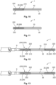
- Figs. 10-15 show cross-sections of current transport mechanisms 1 at a distance in its established plug-in connection devices 202 or plug-in contact sections 220; an, as before, fully circumferentially electrically insulated cross-section of the relevant current transport mechanism 1 is depicted in each case.
- the respective current transport mechanism 1 can have at least one exposed plug-in connection device 202 or one exposed plug-in contact section 220. This is highlighted in Figs. 12 and 13 by means of in each case a mating plug-in connection device 9, which is plugged onto a plug-in connection device 202 which is not depicted or a plug-in contact section 220 which is not depicted.
- Fig. 10 shows an aluminium-based base conductor 10 of a current transport mechanism 1, at which one single copper-based terminal conductor 20 is provided laterally (composite product).
- the terminal conductor 20 is coated on both sides, in particular with silver 222.
- - Fig. 11 shows a configuration which is similar to Fig. 10 , but wherein the terminal conductor 20 and the base conductor 10 are both aluminium-based.
- the terminal conductor 20 is manufactured simultaneously with the base conductor 10 (extrusion, rolling, casting, etc.).
- the base conductor 10 and the terminal conductor 20 are preferably formed monolithically, integrally and/or simply.
- Fig. 12 shows a depiction of the current transport mechanism 1 which is similar to Fig. 10 , but wherein two double-sided, copper-based terminal conductors 20, which are preferably coated with silver 222, are provided at the transverse sides of the aluminium-based base conductor 10.
- Fig. 13 shows a depiction of the current transport mechanism 1 which is similar to Fig. 11 , wherein two double-sided, aluminium-based terminal conductors 20, which are preferably coated with silver 222, are formed at the transverse sides of the also aluminium-based base conductor 10.
- the relevant conductors 10, 20 can be formed with the same thickness.
- Fig. 14 highlights that this does not have to be the case with two terminal conductors 20 at a single base conductor 10, which terminal conductors 20 are of varying thickness and are preferably coated with silver 222.
- the relevant terminal conductor 20 is preferably thinner (left in Fig. 14 ) than the base conductor 10, or preferably has the same thickness (left in Fig. 14 ) as the base conductor 10.
- a coating 222 reaches up to the base conductor 10 and where applicable slightly overlaps it (cf. Figs. 10, 12 , 14, 15 ).
- Fig. 14 shows a current transport mechanism 1 as a bilayer current transport mechanism 1 with two electromechanical conductors 10/20, 10/20 which are electrically insulated from each other.
- a terminal conductor 20 or a predetermined contact region 200 is provided at the relevant base conductor 10 at only one longitudinal side.
- a different number of electromechanical conductors 10/20, 10/20, ... is of course possible (a multilayer current transport mechanism 1).
- a jacket 40, 42 according to the first variant can of course be applied to all exemplary embodiments.
Landscapes
- Engineering & Computer Science (AREA)
- Mechanical Engineering (AREA)
- Power Engineering (AREA)
- Transportation (AREA)
- Connector Housings Or Holding Contact Members (AREA)
- Coupling Device And Connection With Printed Circuit (AREA)
- Connections Effected By Soldering, Adhesion, Or Permanent Deformation (AREA)
Claims (15)
- Stromtransporteinrichtung (1), insbesondere Stromschiene (1), Backbone (1) oder Busbar (1) für die Automobilindustrie, wobeidie Stromtransporteinrichtung (1) einen langgestreckten, elektromechanischen Basisleiter (10) mit einer ihn in Umfangsrichtung vollständig umgebenden elektrischen Isolierung (30) aufweist, unddie elektrische Isolierung (30) wenigstens eine Durchgangsausnehmung (310) aufweist und der Basisleiter (10) in einem Bereich (11) der Durchgangsausnehmung (310) von einer Steckverbindungsvorrichtung (100) elektrisch kontaktiert ist, wobeidie Stromtransporteinrichtung (1) in einem Bereich der Steckverbindungsvorrichtung (100) eine Ummantelung (40) aufweist, wobei die Ummantelung (40) abschnittsweise als ein Steckergehäuse (42) für eine Gegensteckverbindungsvorrichtung (9) ausgebildet ist, dadurch gekennzeichnet, dassdie Ummantelung (40) als eine Umspritzung (40) ausgebildet ist.
- Stromtransporteinrichtung (1) nach dem vorhergehenden Anspruch, dadurch gekennzeichnet, dass die Steckverbindungsvorrichtung (100) einen mechanischen Kontaktabschnitt (110) und einen Steckkontaktabschnitt (120) umfasst, wobei
der mechanische Kontaktabschnitt (110) den Basisleiter (10) im Bereich (11) der Durchgangsausnehmung (310) elektrisch kontaktiert und der Steckkontaktabschnitt (120) vom Basisleiter (10) wegsteht. - Stromtransporteinrichtung (1) nach einem der vorhergehenden Ansprüche, dadurch gekennzeichnet, dass die Ummantelung (40) derart ausgebildet ist, dass sie den Steckkontaktabschnitt (120) der Steckverbindungsvorrichtung (100) fluiddicht, insbesondere wasserdicht oder wasserdampfdicht, gegenüber dem Basisleiter (10) im Bereich (11) der Durchgangsausnehmung (310) abdichtet.
- Stromtransporteinrichtung (1) nach einem der vorhergehenden Ansprüche, dadurch gekennzeichnet, dass:• der Basisleiter (10) als ein elektrostarrmechanischer Basisleiter (10) ausgebildet ist;• die Steckverbindungsvorrichtung (100) als ein Stanzteil oder ein Stanzbiegeteil ausgebildet ist;• die Steckverbindungsvorrichtung (100) als eine Tabkontaktvorrichtung (100) oder eine Stiftkontaktvorrichtung (100) ausgebildet ist;• die Steckverbindungsvorrichtung (100) einteilig, stofflich/adhäsiv einstückig oder einstückig mit dem Basisleiter (10) verbunden ist;• der Basisleiter (10) im Bereich (11) der Durchgangsausnehmung (310) von der Steckverbindungsvorrichtung (100) elektrostarrmechanisch kontaktiert ist; und/oder• der Basisleiter (10) im Bereich (11) der Durchgangsausnehmung (310) desoxidiert ist.
- Stromtransporteinrichtung (1), insbesondere Stromschiene (1), Backbone (1) oder Busbar (1) für die Automobilindustrie, wobeidie Stromtransporteinrichtung (1) einen langgestreckten, elektromechanischen Leiter (10/20) mit einer ihn in Umfangsrichtung vollständig umgebenden elektrischen Isolierung (30) aufweist, wobeidie Stromtransporteinrichtung (1) wenigstens eine Steckverbindungsvorrichtung (202) aufweist, die aus der elektrischen Isolierung (30) und dem elektromechanischen Leiter (10/20) freigelegt ist, wobeidie elektrische Isolierung (30) in einem Bereich um die resultierende Steckverbindungsvorrichtung (202) von der Stromtransporteinrichtung (1) entfernt ist und dadurch gekennzeichnet, dassauch ein Material des elektromechanischen Leiters (10/20) entfernt ist.
- Stromtransporteinrichtung (1) nach dem vorhergehenden Anspruch, dadurch gekennzeichnet, dass die Stromtransporteinrichtung (1) am Außenrand wenigstens einen vorbestimmten Kontaktbereich (200) aufweist, aus welchem heraus die Steckverbindungsvorrichtung (202) freilegbar ist, und
der elektromechanische Leiter (10/20), insbesondere ein elektromechanischer Anschlussleiter (20) des elektromechanischen Leiters (10/20), im Bereich des vorbestimmten Kontaktbereichs (200) bevorzugt beschichtet ist. - Stromtransporteinrichtung (1) nach einem der vorhergehenden Ansprüche, dadurch gekennzeichnet, dassder elektromechanische Leiter (10/20) der Stromtransporteinrichtung (1) aus einem metallischen Verbundwerkstoff, insbesondere einem Aluminium-Kupfer-Verbundwerkstoff, ausgebildet ist, oderder elektromechanische Leiter (10/20) der Stromtransporteinrichtung (1) aus einem einzigen metallischen Werkstoff, insbesondere einem Aluminium-Werkstoff, ausgebildet ist.
- Stromtransporteinrichtung (1) nach einem der vorhergehenden Ansprüche, dadurch gekennzeichnet, dass der elektromechanische Leiter (10/20) einen langgestreckten, elektromechanischen Basisleiter (10) und einen parallel dazu angeordneten langgestreckten, elektromechanischen Anschlussleiter (20) umfasst, wobeider Basisleiter (10) einen ersten metallischen Werkstoff, insbesondere einen aluminiumbasierten Werkstoff, aufweist, und der Anschlussleiter (20) einen zweiten metallischen Werkstoff, insbesondere einen kupferbasierten Werkstoff, aufweist, oderder Basisleiter (10) und der Anschlussleiter (20) denselben metallischen Werkstoff aufweisen und integral oder monolithisch miteinander ausgebildet sind.
- Stromtransporteinrichtung (1) nach einem der vorhergehenden Ansprüche, dadurch gekennzeichnet, dass die Stromtransporteinrichtung (1) an einer oder beiden Längsseiten wenigstens einen vorbestimmten Kontaktbereich (200) aufweist, oder
die Stromtransporteinrichtung (1) an einer oder beiden Längsseiten einen Anschlussleiter (20) aufweist, der sich entlang eines Längsabschnitts des Basisleiters (10) erstreckt, wobei sich der Anschlussleiter (20) bevorzugt entlang einer gesamten Längserstreckung des Basisleiters (10) erstreckt. - Stromtransporteinrichtung (1) nach einem der vorhergehenden Ansprüche, dadurch gekennzeichnet, dass, abgesehen von einer Beschichtung, eine Dicke der Steckverbindungsvorrichtung (202) oder des Anschlussleiters (20) kleiner, gleich oder größer als eine Dicke des Basisleiters (10) ist, und/oder
die Stromtransporteinrichtung (1) als eine Mehrfachschicht-Stromtransporteinrichtung (1) mit einer Mehrzahl von elektromechanischen Leitern (10/20, 10/20,...), insbesondere als eine Doppelschicht-Stromtransporteinrichtung (1) mit zwei elektromechanischen Leitern (10/20, 10/20), ausgebildet ist. - Stromtransporteinrichtung (1) nach einem der vorhergehenden Ansprüche, dadurch gekennzeichnet, dass:• der Basisleiter (10) als ein elektrostarrmechanischer Basisleiter (10) ausgebildet ist;• der Anschlussleiter (20) als ein elektrostarrmechanischer Anschlussleiter (20) ausgebildet ist;• die Steckverbindungsvorrichtung (100) als eine Tabkontaktvorrichtung (100) oder eine Stiftkontaktvorrichtung (100) ausgebildet ist; und/oder• die Steckverbindungsvorrichtung (202) monolithisch, integral, einfach oder stofflich/adhäsiv einstückig mit dem Basisleiter (10) ausgebildet ist.
- Fahrzeug-Stromtransporteinrichtung (1) nach einem der vorhergehenden Ansprüche, insbesondere für ein Kraftfahrzeug, mit einem langgestreckten, elektromechanischen Basisleiter (10), dadurch gekennzeichnet, dass
der Basisleiter (10) wenigstens eine elektrostarrmechanisch damit verbundene elektrostarrmechanische Steckverbindungsvorrichtung (100, 202) umfasst, welche ihrerseits von einer elektrostarrmechanischen Gegensteckverbindungsvorrichtung (9) elektrisch kontaktierbar ist. - Fahrzeug-Stromtransporteinrichtung (1) nach einem der vorhergehenden Ansprüche, dadurch gekennzeichnet, dass die elektrostarrmechanische Verbindung zwischen dem Basisleiter (10) und der Steckverbindungsvorrichtung (100, 202) monolithisch, integral, einfach, stofflich/adhäsiv einstückig, einstückig und/oder einteilig ausgebildet ist.
- Fahrzeug-Stromtransporteinrichtung (1) nach einem der vorhergehenden Ansprüche, dadurch gekennzeichnet, dass:• die Steckverbindungsvorrichtung (100) einen mechanischen Kontaktabschnitt (110) aufweist, mittels welchem die Steckverbindungsvorrichtung (100) auf dem Basisleiter (10) festgelegt ist;• die Steckverbindungsvorrichtung (202) einen Verbundkontaktbereich (210) aufweist, mittels welchem die Steckverbindungsvorrichtung (100) mit dem Basisleiter (10) ausgebildet ist; und/oder• die Steckverbindungsvorrichtung (100, 202) einen Steckkontaktabschnitt (120, 220) aufweist, der von der Gegensteckverbindungsvorrichtung (9) elektrisch und mechanisch kontaktierbar ist.
- Entität (0), Einrichtung (0), Modul (0), Baugruppe (0), Gerät (0), Apparat (0), Maschine (0), Fördermittel (0), Transportmittel (0), System (0) oder Anlage (0) für die Automobilindustrie, dadurch gekennzeichnet, dass
die Entität (0), die Einrichtung (0), das Modul (0), die Baugruppe (0), das Gerät (0), der Apparat (0), die Maschine (0), das Fördermittel (0), das Transportmittel (0), das System (0) oder die Anlage (0) eine Fahrzeug-Stromtransporteinrichtung (1) oder eine Stromtransporteinrichtung (1) nach einem der vorhergehenden Ansprüche aufweist.
Applications Claiming Priority (1)
| Application Number | Priority Date | Filing Date | Title |
|---|---|---|---|
| DE102016124963.7A DE102016124963A1 (de) | 2016-12-20 | 2016-12-20 | Stromtransporteinrichtung, insbesondere elektrische oder elektromechanische Stromschiene |
Publications (2)
| Publication Number | Publication Date |
|---|---|
| EP3339104A1 EP3339104A1 (de) | 2018-06-27 |
| EP3339104B1 true EP3339104B1 (de) | 2025-07-09 |
Family
ID=60923210
Family Applications (1)
| Application Number | Title | Priority Date | Filing Date |
|---|---|---|---|
| EP17207212.6A Active EP3339104B1 (de) | 2016-12-20 | 2017-12-14 | Stromtransporteinrichtung, insbesondere elektrische oder elektromechanische stromschiene |
Country Status (5)
| Country | Link |
|---|---|
| US (1) | US10793007B2 (de) |
| EP (1) | EP3339104B1 (de) |
| JP (1) | JP7048294B2 (de) |
| CN (1) | CN108206443B (de) |
| DE (1) | DE102016124963A1 (de) |
Families Citing this family (7)
| Publication number | Priority date | Publication date | Assignee | Title |
|---|---|---|---|---|
| DE102017102130B4 (de) * | 2017-02-03 | 2019-03-14 | Lisa Dräxlmaier GmbH | Gehäuseelement, elektrische Leitungsanordnung und Herstellungsverfahren dafür |
| JP6874555B2 (ja) * | 2017-06-16 | 2021-05-19 | 株式会社オートネットワーク技術研究所 | バスバーおよび当該バスバーを備えた配線モジュール |
| US10177513B1 (en) * | 2017-12-28 | 2019-01-08 | Lear Corporation | Bus bar assembly with a system to form and secure connections to the terminals on a bus bar |
| DE102018219466A1 (de) | 2018-11-14 | 2020-05-14 | Audi Ag | Verfahren zum Herstellen einer Stromführungseinrichtung, Anschlussdose für eine Fahrzeugbatterie und Kraftfahrzeug |
| JP7123514B2 (ja) * | 2020-06-17 | 2022-08-23 | 矢崎総業株式会社 | 導電構造体 |
| DE102022204677A1 (de) * | 2022-05-12 | 2023-11-16 | Leoni Bordnetz-Systeme Gmbh | Vorrichtung zur elektrischen Leistungsverteilung für ein Kraftfahrzeug |
| CN119550927B (zh) * | 2024-11-30 | 2025-05-27 | 昆山游鸣盛机械科技有限公司 | 一种汽车线路集束支架及其制造模具 |
Citations (2)
| Publication number | Priority date | Publication date | Assignee | Title |
|---|---|---|---|---|
| DE102014004432A1 (de) * | 2013-04-04 | 2014-10-09 | Lisa Dräxlmaier GmbH | Elektrische Leitungsvorrichtung, insbesondere für ein Kraftfahrzeug |
| DE102016107080A1 (de) * | 2016-04-18 | 2017-10-19 | Lisa Dräxlmaier GmbH | Elektrische leitungsanordnung für ein fahrzeug sowie halteteil, kontaktteilaufnahme und montageverfahren |
Family Cites Families (28)
| Publication number | Priority date | Publication date | Assignee | Title |
|---|---|---|---|---|
| FR2469815A1 (fr) * | 1979-11-08 | 1981-05-22 | Cit Alcatel | Barre d'alimentation d'appareillage electrique ou electronique sur batis |
| DE3023341A1 (de) * | 1980-06-21 | 1982-01-14 | Daimler-Benz Ag, 7000 Stuttgart | Stromleiter, insbesondere isolierter stromleiter fuer grossraumfahrzeuge |
| JPH0750969B2 (ja) * | 1988-05-31 | 1995-05-31 | 矢崎総業株式会社 | 電気接続箱 |
| JP2924681B2 (ja) * | 1994-12-28 | 1999-07-26 | 住友電装株式会社 | 電気接続箱 |
| US5759050A (en) * | 1995-02-15 | 1998-06-02 | Sumitomo Wiring Systems, Ltd. | Electrical connection construction between electrical connection box and electronic circuit unit |
| FR2735289B1 (fr) * | 1995-06-09 | 1997-08-22 | Schneider Electric Sa | Procede et dispositif de connexion pour jeu de barres surmoulees |
| US5785542A (en) * | 1996-02-15 | 1998-07-28 | Qbc, Inc. | Electrical distribution system having an improved bus coupler |
| DE59706202D1 (de) * | 1996-11-22 | 2002-03-14 | Draexlmaier Lisa Gmbh | Stromverteilungsvorrichtung |
| JP3676636B2 (ja) * | 1999-12-27 | 2005-07-27 | 矢崎総業株式会社 | 層間接続構造 |
| JP2001209019A (ja) * | 2000-01-25 | 2001-08-03 | Fujitsu Ltd | 音響光学型可変波長te/tmモード変換器、及びこれを用いた可変波長光フィルタ |
| JP2002027636A (ja) * | 2000-07-04 | 2002-01-25 | Sumitomo Wiring Syst Ltd | 高電圧用電気接続箱に用いる回路体 |
| CA2363529A1 (en) * | 2001-11-20 | 2003-05-20 | Fci Americas Technology Inc. | Press-fit bus bar for distributing power |
| US7354280B2 (en) * | 2006-08-08 | 2008-04-08 | Deere & Company | Modular power distribution system |
| CN101510655A (zh) * | 2009-03-20 | 2009-08-19 | 贵州航天电器股份有限公司 | 一种电源馈送结构 |
| DE102009024935A1 (de) * | 2009-06-08 | 2010-12-09 | Siemens Aktiengesellschaft | Herstellung einer Stromschiene mit mehreren Abgriffkontakten aus einer insbesondere vollständig isolierten und aus einer vollständig metallisch galvanisierten Flachprofilschiene |
| GB0910824D0 (en) * | 2009-06-23 | 2009-08-05 | Gen Dynamics United Kingdom Lt | Vehicle power and signal distribution system |
| KR100977089B1 (ko) * | 2009-09-08 | 2010-08-19 | 태인전력시스템(주) | 부스바 및 부스바 가공 방법 |
| DE102010007250B4 (de) * | 2010-02-09 | 2012-03-22 | Pollmann Elektrotechnik Gmbh | Phasenschienensystem |
| DE102010002950A1 (de) * | 2010-03-17 | 2011-09-22 | Robert Bosch Gmbh | Schaltungsanordnung und zugehöriges steuergerät für ein kraftfahrzeug |
| CN202205483U (zh) * | 2011-08-19 | 2012-04-25 | 国电南瑞科技股份有限公司 | 胶封式层叠母排 |
| CN102592712B (zh) * | 2012-03-23 | 2014-02-26 | 株洲博雅科技股份有限公司 | 一种整体式多分支结构铜母线母排制备方法及母排 |
| CN203326319U (zh) * | 2013-04-22 | 2013-12-04 | 苏州西典机电有限公司 | 用于叠层母排的柔性连接机构 |
| CN203883271U (zh) * | 2014-05-22 | 2014-10-15 | 苏州西典机电有限公司 | 一种新型的叠层母排 |
| CN204178734U (zh) * | 2014-10-25 | 2015-02-25 | 广东顺科通信设备实业有限公司 | 一种不间断电源母排 |
| EP3051635B1 (de) * | 2015-01-30 | 2018-01-17 | TE Connectivity Germany GmbH | Elektrische Kontaktmittel und elektrische Kabelanordnung für die Automobilindustrie |
| EP3101745B1 (de) * | 2015-06-03 | 2017-10-04 | Friedrich Göhringer Elektrotechnik GmbH | Mehrphasige sammelschiene mit verbesserter kriechstrecke |
| DE202015104023U1 (de) * | 2015-07-31 | 2016-11-03 | Rogers Germany Gmbh | Stromschiene |
| CN205543582U (zh) * | 2016-03-28 | 2016-08-31 | 乐清市高科环保电子有限公司 | 一种多面板插接式汇流排 |
-
2016
- 2016-12-20 DE DE102016124963.7A patent/DE102016124963A1/de active Pending
-
2017
- 2017-12-14 EP EP17207212.6A patent/EP3339104B1/de active Active
- 2017-12-15 JP JP2017240106A patent/JP7048294B2/ja active Active
- 2017-12-20 CN CN201711384093.2A patent/CN108206443B/zh active Active
- 2017-12-20 US US15/848,898 patent/US10793007B2/en active Active
Patent Citations (2)
| Publication number | Priority date | Publication date | Assignee | Title |
|---|---|---|---|---|
| DE102014004432A1 (de) * | 2013-04-04 | 2014-10-09 | Lisa Dräxlmaier GmbH | Elektrische Leitungsvorrichtung, insbesondere für ein Kraftfahrzeug |
| DE102016107080A1 (de) * | 2016-04-18 | 2017-10-19 | Lisa Dräxlmaier GmbH | Elektrische leitungsanordnung für ein fahrzeug sowie halteteil, kontaktteilaufnahme und montageverfahren |
Also Published As
| Publication number | Publication date |
|---|---|
| US10793007B2 (en) | 2020-10-06 |
| DE102016124963A1 (de) | 2018-06-21 |
| CN108206443B (zh) | 2022-07-08 |
| CN108206443A (zh) | 2018-06-26 |
| JP2018110112A (ja) | 2018-07-12 |
| US20180170189A1 (en) | 2018-06-21 |
| JP7048294B2 (ja) | 2022-04-05 |
| EP3339104A1 (de) | 2018-06-27 |
Similar Documents
| Publication | Publication Date | Title |
|---|---|---|
| EP3339104A1 (de) | Stromtransporteinrichtung, insbesondere elektrische oder elektronische stromschiene | |
| US10096913B2 (en) | Electric wire with terminal metal fitting | |
| US9263808B2 (en) | Connection structural body, connector and method of manufacturing connection structural body | |
| US9070988B2 (en) | Structure and method for connection of connector terminal | |
| US9065188B2 (en) | Electrical connection | |
| US9640877B2 (en) | Connection structure of crimp terminal with respect to wire | |
| US9608339B2 (en) | Crimped terminal attached aluminum electric wire | |
| US9666956B2 (en) | Minute current crimping terminal and minute current wire harness | |
| JPH0722079A (ja) | 防水型圧接コネクタ | |
| CN104221220B (zh) | 具有可卷曲端子的保险丝端帽 | |
| JP2017084600A (ja) | 端子付電線及び端子付電線の製造方法 | |
| US9054435B2 (en) | Conversion terminal device and method for coupling dissimilar metal electrical components | |
| JP5979427B2 (ja) | 導電体 | |
| US8529304B2 (en) | Female electrical contact system with a contact sleeve welded to a contact cover | |
| US10164350B2 (en) | Terminal attached wire | |
| WO2013088992A1 (ja) | 中継端子および電線と端子の接続構造 | |
| US12438297B2 (en) | Busbar portion with integral connection and retention means | |
| JP2014160560A (ja) | 圧着端子および圧着端子を用いたワイヤハーネス | |
| JP6090126B2 (ja) | バッテリーターミナル | |
| JP2001333519A (ja) | 回路体および該回路体を収容したジャンクションボックス | |
| JP2007244145A (ja) | ジョイントコネクタ | |
| JP2007215373A (ja) | 自動車用ジャンクションボックス | |
| WO2015030222A1 (en) | Connection structure of crimp terminal with respect to wire | |
| JP2010192213A (ja) | ワイヤハーネスの接続構造 |
Legal Events
| Date | Code | Title | Description |
|---|---|---|---|
| PUAI | Public reference made under article 153(3) epc to a published international application that has entered the european phase |
Free format text: ORIGINAL CODE: 0009012 |
|
| STAA | Information on the status of an ep patent application or granted ep patent |
Free format text: STATUS: THE APPLICATION HAS BEEN PUBLISHED |
|
| AK | Designated contracting states |
Kind code of ref document: A1 Designated state(s): AL AT BE BG CH CY CZ DE DK EE ES FI FR GB GR HR HU IE IS IT LI LT LU LV MC MK MT NL NO PL PT RO RS SE SI SK SM TR |
|
| AX | Request for extension of the european patent |
Extension state: BA ME |
|
| STAA | Information on the status of an ep patent application or granted ep patent |
Free format text: STATUS: REQUEST FOR EXAMINATION WAS MADE |
|
| 17P | Request for examination filed |
Effective date: 20181221 |
|
| RBV | Designated contracting states (corrected) |
Designated state(s): AL AT BE BG CH CY CZ DE DK EE ES FI FR GB GR HR HU IE IS IT LI LT LU LV MC MK MT NL NO PL PT RO RS SE SI SK SM TR |
|
| STAA | Information on the status of an ep patent application or granted ep patent |
Free format text: STATUS: EXAMINATION IS IN PROGRESS |
|
| 17Q | First examination report despatched |
Effective date: 20220426 |
|
| GRAP | Despatch of communication of intention to grant a patent |
Free format text: ORIGINAL CODE: EPIDOSNIGR1 |
|
| STAA | Information on the status of an ep patent application or granted ep patent |
Free format text: STATUS: GRANT OF PATENT IS INTENDED |
|
| INTG | Intention to grant announced |
Effective date: 20250210 |
|
| GRAS | Grant fee paid |
Free format text: ORIGINAL CODE: EPIDOSNIGR3 |
|
| GRAA | (expected) grant |
Free format text: ORIGINAL CODE: 0009210 |
|
| STAA | Information on the status of an ep patent application or granted ep patent |
Free format text: STATUS: THE PATENT HAS BEEN GRANTED |
|
| AK | Designated contracting states |
Kind code of ref document: B1 Designated state(s): AL AT BE BG CH CY CZ DE DK EE ES FI FR GB GR HR HU IE IS IT LI LT LU LV MC MK MT NL NO PL PT RO RS SE SI SK SM TR |
|
| REG | Reference to a national code |
Ref country code: GB Ref legal event code: FG4D |
|
| REG | Reference to a national code |
Ref country code: CH Ref legal event code: EP |
|
| REG | Reference to a national code |
Ref country code: IE Ref legal event code: FG4D |
|
| REG | Reference to a national code |
Ref country code: DE Ref legal event code: R096 Ref document number: 602017090425 Country of ref document: DE |
|
| REG | Reference to a national code |
Ref country code: NL Ref legal event code: MP Effective date: 20250709 |
|
| PG25 | Lapsed in a contracting state [announced via postgrant information from national office to epo] |
Ref country code: PT Free format text: LAPSE BECAUSE OF FAILURE TO SUBMIT A TRANSLATION OF THE DESCRIPTION OR TO PAY THE FEE WITHIN THE PRESCRIBED TIME-LIMIT Effective date: 20251110 |
|
| PG25 | Lapsed in a contracting state [announced via postgrant information from national office to epo] |
Ref country code: NL Free format text: LAPSE BECAUSE OF FAILURE TO SUBMIT A TRANSLATION OF THE DESCRIPTION OR TO PAY THE FEE WITHIN THE PRESCRIBED TIME-LIMIT Effective date: 20250709 |
|
| REG | Reference to a national code |
Ref country code: AT Ref legal event code: MK05 Ref document number: 1811594 Country of ref document: AT Kind code of ref document: T Effective date: 20250709 |
|
| PG25 | Lapsed in a contracting state [announced via postgrant information from national office to epo] |
Ref country code: IS Free format text: LAPSE BECAUSE OF FAILURE TO SUBMIT A TRANSLATION OF THE DESCRIPTION OR TO PAY THE FEE WITHIN THE PRESCRIBED TIME-LIMIT Effective date: 20251109 |
|
| PGFP | Annual fee paid to national office [announced via postgrant information from national office to epo] |
Ref country code: DE Payment date: 20250930 Year of fee payment: 9 |
|
| PG25 | Lapsed in a contracting state [announced via postgrant information from national office to epo] |
Ref country code: NO Free format text: LAPSE BECAUSE OF FAILURE TO SUBMIT A TRANSLATION OF THE DESCRIPTION OR TO PAY THE FEE WITHIN THE PRESCRIBED TIME-LIMIT Effective date: 20251009 |
|
| REG | Reference to a national code |
Ref country code: LT Ref legal event code: MG9D |
|
| PG25 | Lapsed in a contracting state [announced via postgrant information from national office to epo] |
Ref country code: AT Free format text: LAPSE BECAUSE OF FAILURE TO SUBMIT A TRANSLATION OF THE DESCRIPTION OR TO PAY THE FEE WITHIN THE PRESCRIBED TIME-LIMIT Effective date: 20250709 |
|
| PG25 | Lapsed in a contracting state [announced via postgrant information from national office to epo] |
Ref country code: FI Free format text: LAPSE BECAUSE OF FAILURE TO SUBMIT A TRANSLATION OF THE DESCRIPTION OR TO PAY THE FEE WITHIN THE PRESCRIBED TIME-LIMIT Effective date: 20250709 |
|
| PGFP | Annual fee paid to national office [announced via postgrant information from national office to epo] |
Ref country code: IT Payment date: 20251121 Year of fee payment: 9 |
|
| PG25 | Lapsed in a contracting state [announced via postgrant information from national office to epo] |
Ref country code: HR Free format text: LAPSE BECAUSE OF FAILURE TO SUBMIT A TRANSLATION OF THE DESCRIPTION OR TO PAY THE FEE WITHIN THE PRESCRIBED TIME-LIMIT Effective date: 20250709 |
|
| PGFP | Annual fee paid to national office [announced via postgrant information from national office to epo] |
Ref country code: FR Payment date: 20251008 Year of fee payment: 9 |
|
| PG25 | Lapsed in a contracting state [announced via postgrant information from national office to epo] |
Ref country code: GR Free format text: LAPSE BECAUSE OF FAILURE TO SUBMIT A TRANSLATION OF THE DESCRIPTION OR TO PAY THE FEE WITHIN THE PRESCRIBED TIME-LIMIT Effective date: 20251010 |
|
| PG25 | Lapsed in a contracting state [announced via postgrant information from national office to epo] |
Ref country code: SE Free format text: LAPSE BECAUSE OF FAILURE TO SUBMIT A TRANSLATION OF THE DESCRIPTION OR TO PAY THE FEE WITHIN THE PRESCRIBED TIME-LIMIT Effective date: 20250709 |
|
| PG25 | Lapsed in a contracting state [announced via postgrant information from national office to epo] |
Ref country code: LV Free format text: LAPSE BECAUSE OF FAILURE TO SUBMIT A TRANSLATION OF THE DESCRIPTION OR TO PAY THE FEE WITHIN THE PRESCRIBED TIME-LIMIT Effective date: 20250709 |
|
| PG25 | Lapsed in a contracting state [announced via postgrant information from national office to epo] |
Ref country code: BG Free format text: LAPSE BECAUSE OF FAILURE TO SUBMIT A TRANSLATION OF THE DESCRIPTION OR TO PAY THE FEE WITHIN THE PRESCRIBED TIME-LIMIT Effective date: 20250709 Ref country code: PL Free format text: LAPSE BECAUSE OF FAILURE TO SUBMIT A TRANSLATION OF THE DESCRIPTION OR TO PAY THE FEE WITHIN THE PRESCRIBED TIME-LIMIT Effective date: 20250709 |
|
| PG25 | Lapsed in a contracting state [announced via postgrant information from national office to epo] |
Ref country code: RS Free format text: LAPSE BECAUSE OF FAILURE TO SUBMIT A TRANSLATION OF THE DESCRIPTION OR TO PAY THE FEE WITHIN THE PRESCRIBED TIME-LIMIT Effective date: 20251009 |
|
| PG25 | Lapsed in a contracting state [announced via postgrant information from national office to epo] |
Ref country code: ES Free format text: LAPSE BECAUSE OF FAILURE TO SUBMIT A TRANSLATION OF THE DESCRIPTION OR TO PAY THE FEE WITHIN THE PRESCRIBED TIME-LIMIT Effective date: 20250709 |
|
| PG25 | Lapsed in a contracting state [announced via postgrant information from national office to epo] |
Ref country code: RO Free format text: LAPSE BECAUSE OF FAILURE TO SUBMIT A TRANSLATION OF THE DESCRIPTION OR TO PAY THE FEE WITHIN THE PRESCRIBED TIME-LIMIT Effective date: 20250709 |
|
| PG25 | Lapsed in a contracting state [announced via postgrant information from national office to epo] |
Ref country code: SM Free format text: LAPSE BECAUSE OF FAILURE TO SUBMIT A TRANSLATION OF THE DESCRIPTION OR TO PAY THE FEE WITHIN THE PRESCRIBED TIME-LIMIT Effective date: 20250709 |
|
| PG25 | Lapsed in a contracting state [announced via postgrant information from national office to epo] |
Ref country code: DK Free format text: LAPSE BECAUSE OF FAILURE TO SUBMIT A TRANSLATION OF THE DESCRIPTION OR TO PAY THE FEE WITHIN THE PRESCRIBED TIME-LIMIT Effective date: 20250709 |
|
| PG25 | Lapsed in a contracting state [announced via postgrant information from national office to epo] |
Ref country code: CZ Free format text: LAPSE BECAUSE OF FAILURE TO SUBMIT A TRANSLATION OF THE DESCRIPTION OR TO PAY THE FEE WITHIN THE PRESCRIBED TIME-LIMIT Effective date: 20250709 |
|
| PG25 | Lapsed in a contracting state [announced via postgrant information from national office to epo] |
Ref country code: EE Free format text: LAPSE BECAUSE OF FAILURE TO SUBMIT A TRANSLATION OF THE DESCRIPTION OR TO PAY THE FEE WITHIN THE PRESCRIBED TIME-LIMIT Effective date: 20250709 Ref country code: SK Free format text: LAPSE BECAUSE OF FAILURE TO SUBMIT A TRANSLATION OF THE DESCRIPTION OR TO PAY THE FEE WITHIN THE PRESCRIBED TIME-LIMIT Effective date: 20250709 |
|
| PLBE | No opposition filed within time limit |
Free format text: ORIGINAL CODE: 0009261 |
|
| STAA | Information on the status of an ep patent application or granted ep patent |
Free format text: STATUS: NO OPPOSITION FILED WITHIN TIME LIMIT |