EP3338617A1 - Systèmes et procédés d'imagerie par lunette - Google Patents
Systèmes et procédés d'imagerie par lunette Download PDFInfo
- Publication number
- EP3338617A1 EP3338617A1 EP18156557.3A EP18156557A EP3338617A1 EP 3338617 A1 EP3338617 A1 EP 3338617A1 EP 18156557 A EP18156557 A EP 18156557A EP 3338617 A1 EP3338617 A1 EP 3338617A1
- Authority
- EP
- European Patent Office
- Prior art keywords
- image
- goggle
- goggle device
- imaging
- pixels
- Prior art date
- Legal status (The legal status is an assumption and is not a legal conclusion. Google has not performed a legal analysis and makes no representation as to the accuracy of the status listed.)
- Granted
Links
- 238000003384 imaging method Methods 0.000 title claims description 80
- 238000000034 method Methods 0.000 title claims description 20
- 238000000799 fluorescence microscopy Methods 0.000 claims description 16
- 230000003287 optical effect Effects 0.000 claims description 16
- 230000008878 coupling Effects 0.000 claims description 10
- 238000010168 coupling process Methods 0.000 claims description 10
- 238000005859 coupling reaction Methods 0.000 claims description 10
- 239000004973 liquid crystal related substance Substances 0.000 claims description 6
- 238000001429 visible spectrum Methods 0.000 claims description 5
- 230000000295 complement effect Effects 0.000 claims description 4
- 239000004065 semiconductor Substances 0.000 claims description 4
- 230000000712 assembly Effects 0.000 claims 3
- 238000000429 assembly Methods 0.000 claims 3
- 238000004891 communication Methods 0.000 abstract description 12
- 206010028980 Neoplasm Diseases 0.000 description 31
- 239000003068 molecular probe Substances 0.000 description 23
- 238000010586 diagram Methods 0.000 description 21
- 210000001519 tissue Anatomy 0.000 description 18
- 238000005286 illumination Methods 0.000 description 16
- 239000000975 dye Substances 0.000 description 10
- 239000001046 green dye Substances 0.000 description 10
- MOFVSTNWEDAEEK-UHFFFAOYSA-M indocyanine green Chemical compound [Na+].[O-]S(=O)(=O)CCCCN1C2=CC=C3C=CC=CC3=C2C(C)(C)C1=CC=CC=CC=CC1=[N+](CCCCS([O-])(=O)=O)C2=CC=C(C=CC=C3)C3=C2C1(C)C MOFVSTNWEDAEEK-UHFFFAOYSA-M 0.000 description 10
- 229960004657 indocyanine green Drugs 0.000 description 10
- 230000005284 excitation Effects 0.000 description 9
- 239000007850 fluorescent dye Substances 0.000 description 9
- 238000012935 Averaging Methods 0.000 description 8
- 230000002123 temporal effect Effects 0.000 description 8
- 108090000765 processed proteins & peptides Proteins 0.000 description 7
- 206010073071 hepatocellular carcinoma Diseases 0.000 description 6
- 239000000523 sample Substances 0.000 description 6
- GRAVJJAQKJDGPM-UHFFFAOYSA-N 3-[2-[7-[3-(2-carboxyethyl)-1,1-dimethylbenzo[e]indol-3-ium-2-yl]hepta-2,4,6-trienylidene]-1,1-dimethylbenzo[e]indol-3-yl]propanoic acid;bromide Chemical compound [Br-].OC(=O)CCN1C2=CC=C3C=CC=CC3=C2C(C)(C)\C1=C/C=C/C=C/C=C/C1=[N+](CCC(O)=O)C2=CC=C(C=CC=C3)C3=C2C1(C)C GRAVJJAQKJDGPM-UHFFFAOYSA-N 0.000 description 5
- 238000002073 fluorescence micrograph Methods 0.000 description 5
- 230000006870 function Effects 0.000 description 5
- 231100000844 hepatocellular carcinoma Toxicity 0.000 description 5
- 238000002271 resection Methods 0.000 description 5
- 238000012546 transfer Methods 0.000 description 5
- 210000004881 tumor cell Anatomy 0.000 description 5
- 241000699666 Mus <mouse, genus> Species 0.000 description 4
- 241000699670 Mus sp. Species 0.000 description 4
- 230000003595 spectral effect Effects 0.000 description 4
- 238000001356 surgical procedure Methods 0.000 description 4
- 238000002604 ultrasonography Methods 0.000 description 4
- IAZDPXIOMUYVGZ-UHFFFAOYSA-N Dimethylsulphoxide Chemical compound CS(C)=O IAZDPXIOMUYVGZ-UHFFFAOYSA-N 0.000 description 3
- XEKOWRVHYACXOJ-UHFFFAOYSA-N Ethyl acetate Chemical compound CCOC(C)=O XEKOWRVHYACXOJ-UHFFFAOYSA-N 0.000 description 3
- 150000001875 compounds Chemical class 0.000 description 3
- 238000005516 engineering process Methods 0.000 description 3
- 238000001990 intravenous administration Methods 0.000 description 3
- 210000004185 liver Anatomy 0.000 description 3
- 239000000463 material Substances 0.000 description 3
- 102000004169 proteins and genes Human genes 0.000 description 3
- 108090000623 proteins and genes Proteins 0.000 description 3
- 239000002096 quantum dot Substances 0.000 description 3
- 230000035945 sensitivity Effects 0.000 description 3
- 238000001228 spectrum Methods 0.000 description 3
- HEDRZPFGACZZDS-UHFFFAOYSA-N Chloroform Chemical compound ClC(Cl)Cl HEDRZPFGACZZDS-UHFFFAOYSA-N 0.000 description 2
- 241000283973 Oryctolagus cuniculus Species 0.000 description 2
- 238000010521 absorption reaction Methods 0.000 description 2
- 238000003491 array Methods 0.000 description 2
- WPYMKLBDIGXBTP-UHFFFAOYSA-N benzoic acid Chemical compound OC(=O)C1=CC=CC=C1 WPYMKLBDIGXBTP-UHFFFAOYSA-N 0.000 description 2
- 230000015572 biosynthetic process Effects 0.000 description 2
- 210000004027 cell Anatomy 0.000 description 2
- 239000002872 contrast media Substances 0.000 description 2
- 238000001514 detection method Methods 0.000 description 2
- 238000009792 diffusion process Methods 0.000 description 2
- 230000002209 hydrophobic effect Effects 0.000 description 2
- 230000006872 improvement Effects 0.000 description 2
- 230000010354 integration Effects 0.000 description 2
- 230000003902 lesion Effects 0.000 description 2
- 238000013507 mapping Methods 0.000 description 2
- 239000002105 nanoparticle Substances 0.000 description 2
- 238000003333 near-infrared imaging Methods 0.000 description 2
- 230000001613 neoplastic effect Effects 0.000 description 2
- 210000004882 non-tumor cell Anatomy 0.000 description 2
- 238000012014 optical coherence tomography Methods 0.000 description 2
- 230000010287 polarization Effects 0.000 description 2
- 102000004196 processed proteins & peptides Human genes 0.000 description 2
- 238000006862 quantum yield reaction Methods 0.000 description 2
- 238000000926 separation method Methods 0.000 description 2
- 238000002603 single-photon emission computed tomography Methods 0.000 description 2
- 238000003786 synthesis reaction Methods 0.000 description 2
- 238000003325 tomography Methods 0.000 description 2
- 230000029663 wound healing Effects 0.000 description 2
- CIGDKFCYUOGCBY-UHFFFAOYSA-N (2z)-2-[(2e)-2-[2-chloro-3-[(e)-2-(1-ethyl-3,3-dimethylindol-1-ium-2-yl)ethenyl]cyclohex-2-en-1-ylidene]ethylidene]-1-ethyl-3,3-dimethylindole Chemical compound CC1(C)C2=CC=CC=C2N(CC)\C1=C\C=C/1C(Cl)=C(\C=C\C=2C(C3=CC=CC=C3[N+]=2CC)(C)C)CCC\1 CIGDKFCYUOGCBY-UHFFFAOYSA-N 0.000 description 1
- 102000009027 Albumins Human genes 0.000 description 1
- 108010088751 Albumins Proteins 0.000 description 1
- IYMAXBFPHPZYIK-BQBZGAKWSA-N Arg-Gly-Asp Chemical compound NC(N)=NCCC[C@H](N)C(=O)NCC(=O)N[C@@H](CC(O)=O)C(O)=O IYMAXBFPHPZYIK-BQBZGAKWSA-N 0.000 description 1
- 206010006187 Breast cancer Diseases 0.000 description 1
- 208000026310 Breast neoplasm Diseases 0.000 description 1
- 241000282465 Canis Species 0.000 description 1
- XUJNEKJLAYXESH-UWTATZPHSA-N D-Cysteine Chemical compound SC[C@@H](N)C(O)=O XUJNEKJLAYXESH-UWTATZPHSA-N 0.000 description 1
- 229930195710 D‐cysteine Natural products 0.000 description 1
- 206010019233 Headaches Diseases 0.000 description 1
- 206010019695 Hepatic neoplasm Diseases 0.000 description 1
- 241000282412 Homo Species 0.000 description 1
- 206010061218 Inflammation Diseases 0.000 description 1
- 150000008575 L-amino acids Chemical group 0.000 description 1
- 208000035346 Margins of Excision Diseases 0.000 description 1
- 241001465754 Metazoa Species 0.000 description 1
- 102000035195 Peptidases Human genes 0.000 description 1
- 108091005804 Peptidases Proteins 0.000 description 1
- 239000004365 Protease Substances 0.000 description 1
- 241000700159 Rattus Species 0.000 description 1
- 239000002253 acid Substances 0.000 description 1
- 208000009956 adenocarcinoma Diseases 0.000 description 1
- 108010072041 arginyl-glycyl-aspartic acid Proteins 0.000 description 1
- 208000003464 asthenopia Diseases 0.000 description 1
- 125000001797 benzyl group Chemical group [H]C1=C([H])C([H])=C(C([H])=C1[H])C([H])([H])* 0.000 description 1
- 238000005415 bioluminescence Methods 0.000 description 1
- 230000029918 bioluminescence Effects 0.000 description 1
- 239000000090 biomarker Substances 0.000 description 1
- 238000001574 biopsy Methods 0.000 description 1
- 239000008280 blood Substances 0.000 description 1
- 210000004369 blood Anatomy 0.000 description 1
- 230000017531 blood circulation Effects 0.000 description 1
- 210000004556 brain Anatomy 0.000 description 1
- 239000006227 byproduct Substances 0.000 description 1
- 201000011510 cancer Diseases 0.000 description 1
- 150000001732 carboxylic acid derivatives Chemical class 0.000 description 1
- 238000007675 cardiac surgery Methods 0.000 description 1
- 230000015556 catabolic process Effects 0.000 description 1
- 238000002512 chemotherapy Methods 0.000 description 1
- 230000004087 circulation Effects 0.000 description 1
- 238000007796 conventional method Methods 0.000 description 1
- 125000004122 cyclic group Chemical group 0.000 description 1
- 238000013144 data compression Methods 0.000 description 1
- 230000007423 decrease Effects 0.000 description 1
- 230000003247 decreasing effect Effects 0.000 description 1
- 238000006731 degradation reaction Methods 0.000 description 1
- 230000003111 delayed effect Effects 0.000 description 1
- 230000001419 dependent effect Effects 0.000 description 1
- 230000000881 depressing effect Effects 0.000 description 1
- 238000013461 design Methods 0.000 description 1
- 238000002059 diagnostic imaging Methods 0.000 description 1
- 230000004069 differentiation Effects 0.000 description 1
- 239000003814 drug Substances 0.000 description 1
- 230000009977 dual effect Effects 0.000 description 1
- 230000002526 effect on cardiovascular system Effects 0.000 description 1
- 230000000694 effects Effects 0.000 description 1
- 229940093499 ethyl acetate Drugs 0.000 description 1
- 235000019439 ethyl acetate Nutrition 0.000 description 1
- 238000001914 filtration Methods 0.000 description 1
- 238000001917 fluorescence detection Methods 0.000 description 1
- 231100000869 headache Toxicity 0.000 description 1
- 230000002440 hepatic effect Effects 0.000 description 1
- 238000004128 high performance liquid chromatography Methods 0.000 description 1
- 230000002962 histologic effect Effects 0.000 description 1
- 230000007062 hydrolysis Effects 0.000 description 1
- 238000006460 hydrolysis reaction Methods 0.000 description 1
- 238000010191 image analysis Methods 0.000 description 1
- 238000002675 image-guided surgery Methods 0.000 description 1
- 230000001939 inductive effect Effects 0.000 description 1
- 230000004054 inflammatory process Effects 0.000 description 1
- 230000003834 intracellular effect Effects 0.000 description 1
- 238000007912 intraperitoneal administration Methods 0.000 description 1
- 238000010884 ion-beam technique Methods 0.000 description 1
- 238000002372 labelling Methods 0.000 description 1
- 239000007788 liquid Substances 0.000 description 1
- 208000014018 liver neoplasm Diseases 0.000 description 1
- 238000004020 luminiscence type Methods 0.000 description 1
- 210000001165 lymph node Anatomy 0.000 description 1
- 230000007246 mechanism Effects 0.000 description 1
- 239000000203 mixture Substances 0.000 description 1
- 230000004001 molecular interaction Effects 0.000 description 1
- 230000000771 oncological effect Effects 0.000 description 1
- 238000002559 palpation Methods 0.000 description 1
- 239000000863 peptide conjugate Substances 0.000 description 1
- 125000001997 phenyl group Chemical group [H]C1=C([H])C([H])=C(*)C([H])=C1[H] 0.000 description 1
- 230000008569 process Effects 0.000 description 1
- 238000012545 processing Methods 0.000 description 1
- 210000001747 pupil Anatomy 0.000 description 1
- RQGPLDBZHMVWCH-UHFFFAOYSA-N pyrrolo[3,2-b]pyrrole Chemical compound C1=NC2=CC=NC2=C1 RQGPLDBZHMVWCH-UHFFFAOYSA-N 0.000 description 1
- 238000001959 radiotherapy Methods 0.000 description 1
- 230000009257 reactivity Effects 0.000 description 1
- 230000010837 receptor-mediated endocytosis Effects 0.000 description 1
- 102000005962 receptors Human genes 0.000 description 1
- 108020003175 receptors Proteins 0.000 description 1
- 238000001953 recrystallisation Methods 0.000 description 1
- 238000012216 screening Methods 0.000 description 1
- 210000005005 sentinel lymph node Anatomy 0.000 description 1
- 210000002966 serum Anatomy 0.000 description 1
- 239000007787 solid Substances 0.000 description 1
- 239000007790 solid phase Substances 0.000 description 1
- 238000011477 surgical intervention Methods 0.000 description 1
- 230000001360 synchronised effect Effects 0.000 description 1
- 238000002626 targeted therapy Methods 0.000 description 1
- ANRHNWWPFJCPAZ-UHFFFAOYSA-M thionine Chemical compound [Cl-].C1=CC(N)=CC2=[S+]C3=CC(N)=CC=C3N=C21 ANRHNWWPFJCPAZ-UHFFFAOYSA-M 0.000 description 1
- 238000012285 ultrasound imaging Methods 0.000 description 1
- 238000010200 validation analysis Methods 0.000 description 1
- 230000000007 visual effect Effects 0.000 description 1
- 238000011179 visual inspection Methods 0.000 description 1
Images


Classifications
-
- H—ELECTRICITY
- H04—ELECTRIC COMMUNICATION TECHNIQUE
- H04N—PICTORIAL COMMUNICATION, e.g. TELEVISION
- H04N13/00—Stereoscopic video systems; Multi-view video systems; Details thereof
- H04N13/30—Image reproducers
- H04N13/332—Displays for viewing with the aid of special glasses or head-mounted displays [HMD]
- H04N13/344—Displays for viewing with the aid of special glasses or head-mounted displays [HMD] with head-mounted left-right displays
-
- A—HUMAN NECESSITIES
- A61—MEDICAL OR VETERINARY SCIENCE; HYGIENE
- A61B—DIAGNOSIS; SURGERY; IDENTIFICATION
- A61B34/00—Computer-aided surgery; Manipulators or robots specially adapted for use in surgery
- A61B34/25—User interfaces for surgical systems
-
- A—HUMAN NECESSITIES
- A61—MEDICAL OR VETERINARY SCIENCE; HYGIENE
- A61B—DIAGNOSIS; SURGERY; IDENTIFICATION
- A61B90/00—Instruments, implements or accessories specially adapted for surgery or diagnosis and not covered by any of the groups A61B1/00 - A61B50/00, e.g. for luxation treatment or for protecting wound edges
- A61B90/30—Devices for illuminating a surgical field, the devices having an interrelation with other surgical devices or with a surgical procedure
-
- A—HUMAN NECESSITIES
- A61—MEDICAL OR VETERINARY SCIENCE; HYGIENE
- A61B—DIAGNOSIS; SURGERY; IDENTIFICATION
- A61B90/00—Instruments, implements or accessories specially adapted for surgery or diagnosis and not covered by any of the groups A61B1/00 - A61B50/00, e.g. for luxation treatment or for protecting wound edges
- A61B90/36—Image-producing devices or illumination devices not otherwise provided for
- A61B90/361—Image-producing devices, e.g. surgical cameras
-
- A—HUMAN NECESSITIES
- A61—MEDICAL OR VETERINARY SCIENCE; HYGIENE
- A61K—PREPARATIONS FOR MEDICAL, DENTAL OR TOILETRY PURPOSES
- A61K49/00—Preparations for testing in vivo
- A61K49/001—Preparation for luminescence or biological staining
- A61K49/0013—Luminescence
- A61K49/0017—Fluorescence in vivo
- A61K49/0019—Fluorescence in vivo characterised by the fluorescent group, e.g. oligomeric, polymeric or dendritic molecules
- A61K49/0021—Fluorescence in vivo characterised by the fluorescent group, e.g. oligomeric, polymeric or dendritic molecules the fluorescent group being a small organic molecule
- A61K49/0032—Methine dyes, e.g. cyanine dyes
- A61K49/0034—Indocyanine green, i.e. ICG, cardiogreen
-
- A—HUMAN NECESSITIES
- A61—MEDICAL OR VETERINARY SCIENCE; HYGIENE
- A61K—PREPARATIONS FOR MEDICAL, DENTAL OR TOILETRY PURPOSES
- A61K49/00—Preparations for testing in vivo
- A61K49/001—Preparation for luminescence or biological staining
- A61K49/0013—Luminescence
- A61K49/0017—Fluorescence in vivo
- A61K49/005—Fluorescence in vivo characterised by the carrier molecule carrying the fluorescent agent
- A61K49/0056—Peptides, proteins, polyamino acids
-
- C—CHEMISTRY; METALLURGY
- C07—ORGANIC CHEMISTRY
- C07K—PEPTIDES
- C07K7/00—Peptides having 5 to 20 amino acids in a fully defined sequence; Derivatives thereof
- C07K7/04—Linear peptides containing only normal peptide links
- C07K7/06—Linear peptides containing only normal peptide links having 5 to 11 amino acids
-
- G—PHYSICS
- G02—OPTICS
- G02B—OPTICAL ELEMENTS, SYSTEMS OR APPARATUS
- G02B27/00—Optical systems or apparatus not provided for by any of the groups G02B1/00 - G02B26/00, G02B30/00
- G02B27/01—Head-up displays
- G02B27/017—Head mounted
-
- H—ELECTRICITY
- H04—ELECTRIC COMMUNICATION TECHNIQUE
- H04N—PICTORIAL COMMUNICATION, e.g. TELEVISION
- H04N25/00—Circuitry of solid-state image sensors [SSIS]; Control thereof
- H04N25/70—SSIS architectures; Circuits associated therewith
- H04N25/76—Addressed sensors, e.g. MOS or CMOS sensors
-
- A—HUMAN NECESSITIES
- A61—MEDICAL OR VETERINARY SCIENCE; HYGIENE
- A61B—DIAGNOSIS; SURGERY; IDENTIFICATION
- A61B1/00—Instruments for performing medical examinations of the interior of cavities or tubes of the body by visual or photographical inspection, e.g. endoscopes; Illuminating arrangements therefor
- A61B1/00002—Operational features of endoscopes
- A61B1/00043—Operational features of endoscopes provided with output arrangements
- A61B1/00045—Display arrangement
- A61B1/0005—Display arrangement combining images e.g. side-by-side, superimposed or tiled
-
- A—HUMAN NECESSITIES
- A61—MEDICAL OR VETERINARY SCIENCE; HYGIENE
- A61B—DIAGNOSIS; SURGERY; IDENTIFICATION
- A61B1/00—Instruments for performing medical examinations of the interior of cavities or tubes of the body by visual or photographical inspection, e.g. endoscopes; Illuminating arrangements therefor
- A61B1/06—Instruments for performing medical examinations of the interior of cavities or tubes of the body by visual or photographical inspection, e.g. endoscopes; Illuminating arrangements therefor with illuminating arrangements
- A61B1/0661—Endoscope light sources
- A61B1/0692—Endoscope light sources head mounted
-
- A—HUMAN NECESSITIES
- A61—MEDICAL OR VETERINARY SCIENCE; HYGIENE
- A61B—DIAGNOSIS; SURGERY; IDENTIFICATION
- A61B90/00—Instruments, implements or accessories specially adapted for surgery or diagnosis and not covered by any of the groups A61B1/00 - A61B50/00, e.g. for luxation treatment or for protecting wound edges
- A61B90/36—Image-producing devices or illumination devices not otherwise provided for
- A61B2090/364—Correlation of different images or relation of image positions in respect to the body
Definitions
- the field of the disclosure relates generally to imaging systems and methods, and more specifically, to goggles for displaying a plurality of image modes.
- surgeons typically need to remove large surgical margins around what they perceive as a neoplastic tissue because of the similarity of diseased tissue to surrounding healthy tissue.
- surgeons do not have the luxury of removing sizeable healthy tissue for fear of inducing irreparable damage.
- the human eye is not capable of detecting the contrast signals with high sensitivity in the operating room. This limitation exasperates tumor resection, resulting in the presence of cancerous cells at or near the boundaries of surgically removed tissues.
- Imaging systems have relatively low sensitivity and accuracy. Further, at least some known imaging systems generally require high costs, complex instrumentation, and time-consuming image analysis. Moreover, some surgical procedures often require a team of experienced oncologic surgeons, radiologists, and pathologists to work together. Finally, at least some known imaging systems include a graphic display of results on a monitor, which can distract surgeons from focusing on the surgery at hand.
- a goggle system in one aspect, includes a computing device, a goggle device configured to be worn by a user and including a detector configured to simultaneously acquire image data of a subject in a first image mode and a second image mode, at least one eye assembly configured to display at least one of an image in the first image mode, an image in the second image mode, and a hybrid image including pixels of image data from the first image mode and pixels of image data from the second image mode, and a communications module configured to transmit acquired image data from the goggle device to the computing device.
- a goggle device configured to be worn by a user.
- the goggle device includes a detector configured to simultaneously acquire image data of a subject in a first image mode and a second image mode, and at least one eye assembly configured to display at least one of an image in the first image mode, an image in the second image mode, and a hybrid image including pixels of image data from the first image mode and pixels of image data from the second image mode.
- a method for assembling a goggle device includes providing a detector configured to simultaneously acquire image data of a subject in a first image mode and a second image mode, coupling at least one eye assembly to the detector such that the at least one eye assembly is configured to display at least one of an image in the first image mode, an image in the second image mode, and a hybrid image including pixels of image data from the first image mode and pixels of image data from the second image mode, and coupling a fastening device to the at least one eye assembly, the fastening device configured to secure the goggle device to a user.
- a goggle device for fluorescence imaging configured to be worn by a user.
- the goggle device includes a head-mounted display configured to switch between optical see-through and video see-through modes, a complementary metal-oxide-semiconductor (CMOS) imaging sensor, and a control module configured to interface between the CMOS imaging sensor and a computing device.
- CMOS complementary metal-oxide-semiconductor
- a method for fluorescence imaging includes administering a fluorescent molecular probe to a subject, observing the subject using a goggle device configured for at least one of visible light and near infrared light imaging, and identifying, using the goggle device, at least one tumor in the subject based on a binding of the fluorescent molecular probe to tissue.
- Embodiments described herein provide a goggle system that includes a goggle device in communication with a computing device.
- the goggle device enables a user to view a subject in a plurality of imaging modes in real-time.
- the imaging modes include a hybrid-imaging mode that simultaneously displays pixels of image data of a first imaging mode and pixels of image data of a second imaging mode. Accordingly, a user is able to quickly and easily visualize a subject during a surgical operation.
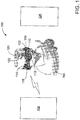
- Fig. 1 is a schematic diagram of an exemplary goggle system 100.
- Fig. 2 is a block diagram of a goggle device 102 that may be used with goggle system 100.
- Goggle device 102 may be worn by a user 104, such as a surgeon, and aids user 104 in viewing a subject 106, as described in detail herein.
- goggle device 102 transmits and/or receives data from a computing device 108. Data may be transferred between computing device 108 and goggle device 102 over a wired or wireless network.
- goggle device 102 includes a left eye assembly 110 that displays an image for a left eye of user 104, and a right eye assembly 112 that displays an image for a right eye of user 104.
- Goggle device 102 further includes a fastening device 114, such as a strap, for securing goggle device 102 to user 104 during use.
- Goggle device 102 enables user 104 to view subject 106 in a plurality of image modes.
- goggle device 102 enables user 104 to view a far- or near-infrared (NIR) image of subject 106, a visible light image of subject 106, and a hybrid near-infrared/visible light image of subject 106.
- NIR far- or near-infrared
- goggle device 102 may enable user 104 to view a subject in any image mode and/or combination of image modes, including, for example photoacoustic images, interference images, optical coherence tomography images, diffusion optical tomography images, polarization images, ultrasound images, and nuclear images (e.g., PET, SPECT, CT, gamma-imaging, X-ray).
- image modes including, for example photoacoustic images, interference images, optical coherence tomography images, diffusion optical tomography images, polarization images, ultrasound images, and nuclear images (e.g., PET, SPECT, CT, gamma-imaging, X-ray).
- a switch 116 on goggle device 102 enables user 104 to switch between image modes.
- switch 116 is a toggle switch.
- switch 116 may be any type of switching device that enables goggle device 102 to function as described herein.
- switch 116 is a foot pedal, and user 104 activates switch 116 by depressing the foot pedal.
- switch 116 is voice-activated.
- Switch 116 controls which image mode is displayed on left eye assembly 110 and right eye assembly 112.
- switch 116 controls whether left eye assembly 110 and/or right eye 112 assembly displays a visible light image, a near-infrared image, or a hybrid near-infrared/visible light image.
- left eye assembly 110 and right eye assembly 112 each have a respective switch 116. Accordingly, in some embodiments, user 104 may view a first image mode on left eye assembly 110, and a second image mode on right eye assembly 112.
- Goggle device 102 further includes sources for imaging.
- goggle device includes a white light (i.e. visible light) source 120 and a near-infrared light source 122.
- White light source 120 and near-infrared light source 122 illuminate subject 106 with visible light and near-infrared light, respectively.
- different light sources may be utilized for different specific imaging modes.
- suitable light sources may be integrated with goggle device 102 to enable capture of photoacoustic images, interference images, optical coherence tomography images, diffusion optical tomography images, polarization images, far infrared images, thermal images, ultrasound images, and nuclear images (e.g., PET, SPECT, CT, gamma-imaging, X-ray).
- photoacoustic images interference images, optical coherence tomography images, diffusion optical tomography images, polarization images, far infrared images, thermal images, ultrasound images, and nuclear images (e.g., PET, SPECT, CT, gamma-imaging, X-ray).
- white light source 120 includes a plurality of white light emitting diodes (LEDs), and near-infrared light source 122 includes a plurality of near-infrared LEDs for fluorescence imaging.
- White light source 120 and near-infrared light source 122 each provide a field of view of approximately 0.3 m in diameter at 1.0 m from the respective source.
- white light source 120 and near-infrared light source 122 including any components that enable goggle device 102 to function as described herein, such as , for example, laser, laser diodes, light bulbs, or any combination of the aforementioned components.
- near-infrared light source 122 may include light sources in other wavelengths to enable absorption or luminescence or fluorescence imaging in other spectral windows.
- Near-infrared light emitted from near-infrared light source 122 excites fluorescent molecular probes present in subject 106.
- a molecular probe capable of fluorescent excitation is injected into a subject.
- the molecular probe includes a peptide sequence and a near-infrared fluorescent dye, such as indocyanine green dye having absorption and emission maxima around 780 nm and 830 nm, respectively. After injecting the molecular probe into the subject 106, molecular probe binds to tumors.
- the fluorescent dye in molecular probe is excited.
- lesions such as tumors can quickly and easily be visualized in the near-infrared imaging mode of goggle device 102.
- a similar procedure is applicable in other spectral regions.
- goggle device To transfer data between goggle device 102 and one or more remote devices, such as computing device 108, goggle device includes a communications module 130.
- communications module 130 includes a radio-frequency (RF) transmitter/receiver. Data transfer can also be accomplished through other suitable platforms such as, for example, bluetooth, WI-FI, IR communication, internet, 3G, 4G network, satellite, etc.
- Communications module 130 may also be transfer data to computing device 108 over a wired connection, such as, for example a USB video capture cable.
- Communications module 130 enables image data collected by goggles to be displayed and/or stored on computing device 108. Accordingly, image data acquired by goggle device 102 can be viewed not only on goggle device 102, but also computing device 108.
- Goggle device 102 includes a power module 140 that supplies power to goggle device 102.
- power module 140 is a battery unit that stores and provides electrical energy to goggle device 102.
- power module 140 is any device configured to supply power to goggle device 102.
- goggle device 102 includes a detector module 150.
- detector module 150 is a hybrid detector array capable of detecting both near-infrared and visible light.
- Detector module 150 is mounted on a front of goggle device 102 to collect image data from a direction that user 104 is facing.
- Detector module 150 displays received image data on left eye assembly 110 and right eye assembly 112 such that left eye assembly 110 and right eye assembly 112 display the same regions of subject 106 that a left eye and right eye of user 104 would observe in the absence of goggle device 102.
- Fig. 3 is an image of an alternative goggle device 300 that may be used with goggle system 100 (shown in Fig. 1 ).
- Goggle device 300 includes components substantially similar to goggle device 102, and like reference numerals are used herein to identify like components.
- goggle device 300 includes only a single eye assembly 302. As such, when using goggle device 300, one eye of user 104 views subject 106 through single eye assembly 302, and the other eye of user 104 views subject uninhibited (i.e., with the naked eye).
- Single eye assembly 302 functions substantially similar to left eye assembly 110 and right eye assembly 112 (shown in Figs. 1 and 2 ). In the exemplary embodiment, single eye assembly 302 covers the left eye of user 104. Alternatively, single eye assembly 302 may cover the right eye of user 104.
- Fig. 4 is a schematic diagram of a detector element 400 that may be used with detector module 150 to collect image data for goggle device 102 (both shown in Figs. 1 and 2 ).
- Detector element 400 includes a plurality of differential layers 402 (denoted by Dn) along a differential length in continuum.
- each differential layer 402 is a p-n junction 404.
- detector element 400 includes eleven differential layers 402.
- detector element 400 may include any number of differential layers 402 that enables detector element 400 to function as described herein.
- each layer 402 is configured to detect a different frequency range of incident light.
- channels D5-D8 detect blue light (i.e., light with a wavelength of approximately 440-490 nm), and the total wavelength spectrum detectable by detector element 400 is less than 300 nm to greater than 1300 nm.
- detector element 400 is capable of simultaneously detecting a broad range of wavelengths of incident light, including visible light (i.e., red, green, and blue light), near-infrared light, and various other wavelengths.
- Images can be generated from the image data acquired by a selection of differential layers 402. For example, to generate a visible light image, image data from differential layers 402 corresponding to red, blue, and green light is used. Further, images may be generated using addition, subtraction, integration, differentiation, and/or thresholding of differential layers 402. Accordingly, image data acquired using detector element 400 may be used to generate a variety of images.
- Fig. 5 is a schematic diagram of a portion of a detector array 500 that may be used with detector module 150 (shown in Fig. 2 ).
- Detector array 500 includes a plurality of detector elements 502. In some embodiments, each detector element 502 corresponds to one pixel.
- array 500 includes near-infrared detector elements 504 and visible light detector elements 506 arranged in a checkerboard pattern. That is near-infrared detector elements 504 and visible light detector elements 506 alternate in both a horizontal and vertical direction. Notably, this concept is not restricted to near-infrared detector elements or visible pixel elements.
- near-infrared detector elements 504 and/or visible pixel detector elements 506 may be replaced detector elements in other wavelength windows, such as, for example, 500nm-550nm, 600nm-630nm, 1100nm-1150nm, 1200nm-1300nm, etc.
- visible light detector elements 506 are continuum detector elements, such as detector element 400 (shown in Fig. 4 ), and near-infrared detector elements 504 are single channel detector elements.
- visible light detector elements 506 and near-infrared detector elements 504 may be any type of detector element that enables detector array 500 to function as described herein.
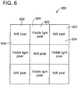
- Fig. 6 is a schematic diagram of a portion of a pixel array 600 displayed by left eye assembly 110 and right eye assembly 112. Similar to the arrangement of detector array 500, pixel array 600 includes a plurality of pixels 602 including near-infrared pixels 604 and visible light pixels 606 arranged in a checkerboard pattern. In the exemplary embodiment, detector elements 502 correspond to pixels 602. As such, in the exemplary embodiment, to display different imaging modes on left eye assembly 110 and/or right eye assembly 112, different combinations of detector elements 602 are utilized such that different combinations of near-infrared pixels 604 and visible light pixels 606 and are displayed.
- switch 116 when switch 116 (shown in Fig. 1 ) is set to a visible light imaging mode, visible light pixels 506 are used and near-infrared pixels 504 are not used for imaging, such that visible light pixels 606 create a visible light image.
- switch 116 when switch 116 is set to a near-infrared imaging mode, near-infrared pixels 504 are used and visible light pixels 506 are not used for imaging, such that near-infrared pixels 604 create a near-infrared image.
- a hybrid imaging mode both near-infrared detectors 504 and visible light detectors 506 are used for imaging, creating an image including near-infrared pixels 604 and visible light pixels 606. Filtering for the different imaging modes may be accomplished by a filter and/or polarizer (neither shown).
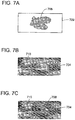
- Figs. 7A-7C are schematic diagrams of a near-infrared image 702, a visible light image 704, and a hybrid image 706, respectively, that may be displayed on goggle device 102 (shown in Figs. 1 and 2 ).
- the molecular probe excited by near-infrared light source 122 shown in Fig. 1
- visible light image 704 subject 710 is visible, but tumor 708 is not visible.
- hybrid image 706 however, both tumor 708 and subject 710 are visible. Accordingly, when user 104 views hybrid image 706 on goggle device 102, both tumors 708 and subject 710 are visible, enabling user 104 to better perform a surgical operation.
- Figs. 8A-8C are a near-infrared image 802, a visible light image 804, and a hybrid image 806. respectively, of a mouse 808 with tumors 810.
- the tumors 810 are visible, but the rest of mouse 808 is not visible.
- visible light image 804 mouse 808 is visible, but tumors 810 are not visible.
- images 802, 804, and/or 806 may also be viewed on computing device 108 (shown in Fig. 1 ).
- Fig. 9 is an image of an alternative goggle device 900 that may be used with goggle system 100 (shown in Fig. 1 ).
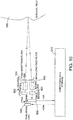
- Fig. 10 is a block diagram of the goggle device 900 shown in Fig. 9 .
- goggle device 900 is ahead-mounted display (HMD) capable of fast temporal resolution and switching between an optical see-through mode and a video see-through mode.
- HMD ahead-mounted display
- user 104 sees the real world through half-transparent mirrors, and the half-transparent mirrors are also used to reflect computer-generated images into eyes of user 104, combining real and virtual world views.
- cameras or other suitable detection devices capture the real-world view, and computer-generated images are electronically combined with the video representation of the real world view.
- both the real and virtual world images are digital in the video see-through mode, lag between the real and virtual world images can be reduced.
- optical see-through mode user 104 can visualize surroundings with natural vision.
- video see-through mode real time NIR fluorescence video is presented to user 104 with relatively high contrast. Allowing user 104 to switch between optical and video see-through modes simplifies surgical operations and allows user 104 to visualize subject 106 with natural vision or enhanced vision as desired.
- Goggle device 900 includes a complementary metal-oxide-semiconductor (CMOS) imaging sensor 902 integrated onto a custom printed circuit board (PCB) platform (not shown).
- CMOS complementary metal-oxide-semiconductor
- PCB printed circuit board
- goggle device 900 may include a charge-coupled device (CCD) imaging sensor.
- CCD charge-coupled device
- a long-pass filter 904 is mounted on an objective imaging lens 906.
- long-pass filter 904 is an 830 nanometer (nm) filter.
- a control module 908 interfaces between CMOS imaging sensor 902 and a computing device 910, such as computing device 108.
- control module 908 includes a field-programmable gate array (FPGA) integration model with universal serial bus (USB) communication capabilities and a laptop computer.
- FPGA field-programmable gate array
- USB universal serial bus
- Data received by CMOS imaging sensor 902 is read out in multiple stages.
- data from CMOS imaging sensor 902 is read out via a state machine implemented on the FPGA and the data is stored in a first in first out (FIFO) process, and transferred to a first synchronous dynamic random-access memory (SDRAM) chip in control module 908.
- FIFO first in first out
- SDRAM synchronous dynamic random-access memory
- control module 908 includes two SDRAM chips, such that a first SDRAM chip stores pixel data from CMOS imaging sensor 902, while a second SDRAM chip transfers the data to an output FIFO on the FPGA for transferring the data to computing device 910 via USB.
- control module 908 may include a data compression chip for compressing the data.
- goggle device 900 includes a HMD unit 920 that interfaces with computing device 910 via a high-definition multimedia interface (HDMI) link to display real time images on HMD unit 920.
- Goggle device 900 further includes and NIR light source 922 that emits NIR light through illumination optics 924 and a short-pass filter 926 to illuminate fluorescent molecular probes (such as indocyanine green dye) in a surgical field 930.
- Surgical field 930 may be, for example, a portion of subject 106 (shown in Fig. 1 ).
- NIR light source 922 includes four NIR LEDs
- short-pass filter 926 is a 775 nm filter.
- a sensitivity of goggle device 900 to detect a fluorescence signal from surgical field 930 is characterized using a signal to noise ratio (SNR), which compares a level of desired signal relative to a noise level.
- SNR signal to noise ratio
- Pixel binning and temporal averaging may be used to improve SNR of goggle device 900.
- Pixel binning involves combining signals from a group of pixels in a spatial domain, which is analogous to increasing the number of photons that contribute to the detected signal. Binning improves the SNR estimate by the square root of the number of pixels binned. For instance, binning a neighborhood of 2 by 2 pixels improves the SNR by a factor of 2. However, improvement in SNR due to binning occurs at the expense of reduced spatial resolution and loss of high spatial frequency components in a final image.
- Temporal averaging involves combing signals from a group of pixels in a time domain, which like binning, is also analogous to increasing the number of photons that contribute to the detected signal. Temporal averaging increases SNR by the square root of the number of averaged pixels in the time domain. Hence, temporal averaging of four consecutive frames will increase SNR by a factor of 2. However, temporal averaging may create image lag when a moving target is imaged.
- Both temporal averaging and pixel binning may be combined together to further improve SNR. For example, averaging 4 frames as well as averaging a pixel neighborhood of 2 by 2 pixels will improve SNR by a factor of 4, while reducing spatial and temporal resolution by a factor of 4. It was determined experimentally that SNR increases linearly with exposure time at a rate that depends on a concentration of a fluorescent molecular probe (e.g., indocyanine green dye). As the exposure time increases, SNR increases at the cost of a slower frame rate.
- a fluorescent molecular probe e.g., indocyanine green dye
- goggle device 900 uses NIR quantum dots (QDs), and fluorescence-guided liver surgery and intraoperative imaging were performed on mice.
- Goggle device 900 is capable of real time fluorescence imaging of up to 60 frames per second (fps). Experimentally, it was determined that goggle device 900 detects fluorescence signals as low as 300 picomolar (pM) of indocyanine green dye. Compared to a charge-coupled device (CCD) imaging sensor, which has 20% quantum efficiency at 830nm, CMOS imaging sensor 902 has a quantum efficiency of greater than 30% at 830 nm. Further, in the exemplary embodiment, goggle device 900 includes one or more buttons and/or switches (neither shown) for user 104 to select automatic or manual gain, and automatic or manual exposure time.
- CCD charge-coupled device
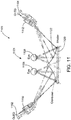
- Fig. 11 is a schematic diagram of a display module 1101 for an alternative goggle device 1100 that may be used with goggle system 100 (shown in Fig. 1 ). Similar to goggle device 900, goggle device 1100 is implemented in a dual mode visual and optical see-through HMD. However, unlike goggle device 900, goggle device 1100 provides three-dimensional (3D) imaging and display, as described herein. In one embodiment, a field of view for illumination and imaging of goggle device 1100 is 300 mm x 240 mm at a distance between goggle device 1100 and subject 106 of 0.3 m -1.2 m.
- 3D three-dimensional
- Display module 1101 of goggle device 1100 includes a first organic light emitting diode (OLED) 1102 and a second OLED 1104 to display images to a right eye 1106 and left eye 1108, respectively of user 104.
- First OLED 1102 emits light through a first optical assembly (e.g., imaging and/or focusing lenses) 1110, and second OLED 1104 emits light through a second optical assembly 1112.
- first optical assembly e.g., imaging and/or focusing lenses
- OLED display technology provides benefits over liquid crystal display (LCD) technology as it uses approximately 80% less power than LCDs, has a nominal viewing area of approximately 160° (approximately 265% larger than LCDs), a nominal contrast ration of 10,000:1 (as compared to 60:1 for LCDs), and a significantly faster refresh rate, reducing eye fatigue and headaches.
- the OLED microdisplay is also more compact than its LCD counterpart because no additional illumination is needed.
- the proposed field of view of the display is 45°x36° with a microdisplay resolution of 1280x1024 (SXGA).
- the pupil size of the goggle device 1100 is 10 mm in diameter. Off-axis design with aspherical plastic elements may be used to reduce the size and weight of goggle device 1100.
- goggle device 1100 includes a fast liquid crystal shutter 1120 positioned in front of a combiner 1122.
- combiner 1122 is a plastic element with 50% reflection on an inner (i.e., eye-facing) surface such that user 104 can see through combiner 1122 in optical see-through mode, and information from OLEDs 1102 and 1104 can be directed to user 104 in both modes.
- fast liquid crystal shutter 1120 When an external voltage is applied, fast liquid crystal shutter 1120 is transparent and transmits light. Without an external voltage, fast liquid crystal shutter 1120 blocks light from the surgical field and environment. Therefore, the goggle device 1110 can be switched between optical and video see-through modes easily and rapidly.
- a switch (not shown) may be controlled by a foot paddle to enable hands-free operation.
- 3D reflectance images and fluorescence image can be registered and presented precisely. The 3D fluorescence images can also be viewed with the optical-see-through mode, while user 104 views the surrounding environment naturally.
- Fig. 12 is a schematic diagram of an imaging and illumination module 1150 for goggle device 1100.
- imaging and illumination module 1150 includes two separate and identical imaging systems, and one illumination system between and above the imaging systems that provides uniform NIR illumination to excite fluorescent molecular probes and visible light illumination for reflectance imaging.
- Each of the two imaging systems includes a CMOS detector 1152 and an imaging lens 1154 in the exemplary embodiment.
- CMOS detectors 1152 provide higher resolution and faster frame rates than CCD detectors.
- the distance between the imaging systems is 67 mm (the average inter-pupillary distance for adults).
- the illumination system includes a first LED array 1160 and a second LED array 1162.
- first LED array 1160 is a high power 780 nm LED array that includes 60 diode chips and an optical output power of 4 Watts (W)
- second LED array 1162 is a high power white light LED array that includes 16 diode chips to provide uniform illumination over an area of 300 x 240 mm.
- the power of NIR excitation is approximately 3mW/cm 2 in the exemplary embodiment.
- Illumination optics 1172 include freeform plastic lenses (not shown) that generate uniform light distribution and an excitation filter (not shown) that blocks excitation light over 800 nm.
- each CMOS detector 1152 and imaging lens 1154 capture white light reflectance and NIR fluorescence images simultaneously.
- each CMOS detector 1152 includes a sensor of vertically-stacked photodiodes and pixelated NIR/visible spectrum filters. More specifically, in the exemplary embodiment, CMOS detector 1152 includes an array of 2268 x 1512 imaging pixels, and each pixel includes three vertically-stacked photodiodes that can separate spectra of blue, green, and red-NIR light for color imaging. As each pixel includes three vertically-stacked diodes, unlike at least some known imaging systems, there is no need to interpolate between neighboring pixels.
- CMOS detector 1152 may be as fast as 40 fps, and a subset of the pixel array can be read out at higher frame rates (e.g., 550 fps for 128 x 128 pixels).
- Fig. 13 is a schematic diagram of a filter array 1300 that may be used with CMOS detector 1152 (shown in Fig. 12 ).
- Filter array 1300 alternates between pixels with a visible spectrum filter 1302 and pixels with a NIR filter 1304.
- Filter array 1300 may be created by taking an NIR filter the size of the entire array 1300 and selectively removing portions using a focus ion beam (FIB).
- Visible filters 1302 which are the selectively removed parts of the larger NIR filter, will allow passage of visible spectrum light which will be subsequently absorbed by the vertically-stacked photodiodes 1306 for color separation.
- NIR filters 1304 will only allow NIR light of interest ( ⁇ >820 nm) to pass, and the NIR signal will be read out from the deepest of vertically-stacked photodiodes 1306. Due to the net effect of both spectrum separation mechanisms (NIR filter 1304 and vertically-stacked photodiodes 1306), the performance of NIR fluorescence detection will be further enhanced compared to conventional method of using an NIR filter alone.
- the CMOS detector 1152 enables co-registration of color images and NIR images on-chip, while reducing the number of sensors required for 3D reflectance/fluorescence imaging. This facilitates eliminating artifacts in co-registration due to motion and minimizes the delay due to exhausting off-chip computation.
- Goggle device 1100 includes an autofocus feature without moving pans that optimizes a focus in the exemplary embodiment.
- a zoom lens with a compact piezo actuator, or a liquid lens with variable, voltage-dependent focal length may be used to implement the autofocus feature.
- image processing for goggle device 1100 is performed by a FPGA coupled to CMOS detectors 1152 and OLEDs 1102 and 1104.
- the goggle devices described herein may be used with or without contrast agents.
- imaging signals for endogenous fluorophores or biomolecules may be used to provide imaging contrast.
- At least some embodiments utilizes NIR fluorescent or luminescent molecules or materials that localize selectively in a tissue of interest.
- indocyanine green dye may be used as a fluorescent molecular probe with the goggle devices described herein.
- Other fluorescent dyes such as NIR pyrrolopyrrole cyanine dyes or luminescent materials such as quantum dots or dye-loaded nanoparticles may be utilized.
- uptake of high affinity probes in small tumor cells may be overwhelmed by background fluorescence from normal tissue, decreasing contrast between tumor cells and background tissue.
- the fluorescent molecules such as dyes, or materials such as luminescent nanoparticles, could be linked to another molecule or group of molecules that will improve selective uptake in the tissues or cells of interest.
- fluorescent molecular probes that bind selectively to protein receptors or other biomarkers overexpressed in tumor cells or target tissue may also be utilized with the goggle devices described herein.
- Figs. 14A-14D are a plurality of exemplary fluorescent molecular probes.
- Fig. 14A shows indocyanine green dye.
- Cypate, shown in Fig. 14B is an NIR cyanine dye with similar spectral properties to indocyanine green dye.
- Cypate, LS-276, shown in Fig. 14C , and LS-288, shown in Fig. 14D are models of hydrophobic, intermediate hydrophilic, and hydrophilic dyes, respectively.
- LS-301 An example of a tumor-targeted molecular probe is LS-301, which has the structure, Cypate-cyclo (D-Cys-Gly-Arg--Asp-Ser-Pro-Cys)-Lys-OH.
- the spectral properties of LS-301 are suitable for NIR imaging applications (e.g., excitation/emission 790/810 nm in 20% DMSO solution; fluorescence quantum yield ( ⁇ ) 0.1 referenced to ICG).
- the unnatural D-cysteine on the peptide moiety confers higher stability because of its resistance to degradation by proteases. This biological stability in serum allows initial imaging and potential follow-up surgery to be conducted within 48 hours before subsequent hydrolysis of the probe through L-amino acid residues.
- NIR fluorescence microscopy of LS-301 in diverse tumor cells showed punctate intracellular fluorescence typical of receptor-mediated endocytosis, and barely visible uptake in non-tumor cells. This uptake was successfully inhibited with unlabeled cyclic (RGDFV) reference peptide in A549 tumor cells, demonstrating the versatility of the imaging probe in detecting tumors relative to non-tumor cells.
- RGDFV unlabeled cyclic
- Hydrophobic dyes such as cypate bind to albumin and other proteins.
- the high binding constant decreases their bioavailability for the target tumors and prolongs the blood circulation time, thereby increasing background fluorescence at early imaging time points.
- more hydrophilic dyes and their peptide conjugates rapidly extravasate into tissues, quickly removing the probe from circulation.
- the hydrophilic probes are suitable for image-guided surgery because of the fast clearance, the contrast between tumor and surrounding tissue also depends on having sufficient time for molecular interaction between the target tumor proteins and the molecular probe.
- the low background signal obtained may be offset by the low signal at the tumor site.
- Experimental data suggests that LS-276 dye (shown in Fig. 14C ) will bridge the gap between rapid and delayed blood clearance, which affects bioavailability of the probes to target tissue.
- LS-276 Due to a direct linkage of carboxylic acid with a phenyl group in LS-276, LS-276 may have a relatively low reactivity with peptides and proteins, resulting in multiple side products that are difficult to remove. Accordingly, in some embodiments, a fluorophore based on a benzyl instead of the current phenyl carboxylic acid used for LS-276 may be utilized. Since the pure compound is a solid, re-crystallization methods may be used where ethylacetate and chloroform mixtures are used to precipitate the dye in >99% HPLC/HRMS purity.
- Fig. 15 is a schematic diagram of the synthesis of reactive benzlycaboxlyic acid for solid phase labeling of LS-301 peptide.
- this derivative of LS-276 may double the quantum yield of cypate used in LS-301.
- the method may produce the desired compound in high yield (>70%) and purity (>99%).
- the method is also scalable, with the potential to produce up to 10 grams of compound.
- the LS-301 peptide may be slighted altered to assess further improvements in tumor selectivity (e.g., cyclo(DCys-Gly-Arg-4sp-Ser-Pro-DCys)-Lys-OH, cyclo(Gys-Gly-Arg-4sp-Ser-Pro-Cys)-Lys-OH, cyclo(Cys-Arg-Gly-Asp-Ser-Fro-Cys)-Lys-OH, cyclo(DCys-Arg-Gly-Asp-Ser-Pro-Cys)-Lys-OH, and cyclo(DCys-Arg-Gly-Asp-Ser-Pro-DCys)-Lys-OH).
- These peptides are labeled with dye 2 at the N-terminus.
- the goggle devices and fluorescent probes described herein may be implemented in a plurality of surgical settings, including, but not limited to, detecting tumors related to breast cancer in mice, adenocarcinoma in canines, and hepatocellular carcinoma (HCC) in humans.
- the goggle devices and fluorescent probes described herein assist in identifying tumor boundaries and performing biopsies.
- the goggle devices and fluorescent probes described herein are also applicable to other surgical interventions such as cardiac surgery and assessing wound healing.
- goggle device 102 shown in Fig. 1
- the fluorescent probe LS-301 described herein were utilized in mapping positive lymph nodes (PLNs) in mice. Based on information provided by non-invasive fluorescence imaging using goggle device 102 and LS-301, regions of interest that might contain PLNs were explored and examined. PLNs were identified and resected under image guidance. The presence of cancerous tissue in the PLNs was confirmed by bioluminescence imaging. This verifies the feasibility of the non-invasive fluorescence imaging, allowing clinicians to rapidly stage cancer non-invasively. Using goggle device 102 and fluorescent probe LS-301 non-invasively can provide a first-line screening that provides general information in an operating room in real time. Further, the fluorescence signals monitored in PLNs might be used as an indicator for efficacy of treatment regimes such as radiotherapy, chemotherapy, and targeted therapy.
- treatment regimes such as radiotherapy, chemotherapy, and targeted therapy.
- a multimodal detection technique was implemented in which goggle-aided fluorescence imaging (e.g., using goggle device 102 (shown in Fig. 1 ) and indocyanine green dye) was combined with ultrasound imaging and standard histology.
- fluorescence imaging was used to detect liver tumors in mice and to perform liver resections on the tumors. In addition to single tumors, scattered satellite lesions were also detected.
- liver resection was performed on a rabbit using ultrasound, fluorescence imaging, and standard histology. The presence of tumors in the rabbit was confirmed by ultrasound, and then observed in real time using fluorescence goggle system 100 (shown in Fig. 1 ). The excised tissues were later examined by histopathology, and it was confirmed that the tumors were cancerous.
- goggle device 102 shown in Fig. 1
- indocyanine green dye were used to image hepatocellular carcinoma (HCC) in human patients.
- HCC hepatocellular carcinoma
- TAH transarterial hepatic
- Primary tumors and satellite tumors were both detected using fluorescence imaging, some of which were not identified in pre-operative MIR and CT images or by visual inspection and palpation. Histologic validation was used to confirm HCC in the patients.
- the HCC-to-liver fluorescence contrast detected by goggle device 102 was significantly higher in patients that received TAH delivery instead of intravenous delivery.
- the systems and methods described herein provide a goggle device in communication with a computing device.
- the goggle device enables a user to view a subject in a plurality of imaging modes in real-time.
- the imaging modes include a hybrid-imaging mode that simultaneously captures and displays pixels of image data of a first imaging mode and pixels of image data of a second imaging mode. Accordingly, a user is able to quickly and easily visualize a subject during a surgical operation.
- the goggle system and goggle device described herein may be utilized in a broad variety of medical applications, including small animal imaging, veterinary medicine, human clinical applications, endoscopic applications, laparoscopic applications, dental applications, cardiovascular imaging, imaging inflammations, wound healing, etc. Further, the goggle system and goggle device described herein may be used in other imaging applications, outside of the medical field.
Landscapes
- Health & Medical Sciences (AREA)
- Life Sciences & Earth Sciences (AREA)
- Engineering & Computer Science (AREA)
- Surgery (AREA)
- General Health & Medical Sciences (AREA)
- Veterinary Medicine (AREA)
- Biomedical Technology (AREA)
- Animal Behavior & Ethology (AREA)
- Public Health (AREA)
- Molecular Biology (AREA)
- Nuclear Medicine, Radiotherapy & Molecular Imaging (AREA)
- Heart & Thoracic Surgery (AREA)
- Medical Informatics (AREA)
- Oral & Maxillofacial Surgery (AREA)
- Pathology (AREA)
- Epidemiology (AREA)
- Chemical & Material Sciences (AREA)
- Proteomics, Peptides & Aminoacids (AREA)
- Organic Chemistry (AREA)
- Signal Processing (AREA)
- Multimedia (AREA)
- Physics & Mathematics (AREA)
- Human Computer Interaction (AREA)
- Robotics (AREA)
- Genetics & Genomics (AREA)
- Medicinal Chemistry (AREA)
- Biophysics (AREA)
- Biochemistry (AREA)
- General Physics & Mathematics (AREA)
- Optics & Photonics (AREA)
- Investigating, Analyzing Materials By Fluorescence Or Luminescence (AREA)
- Eye Examination Apparatus (AREA)
Priority Applications (1)
| Application Number | Priority Date | Filing Date | Title |
|---|---|---|---|
| EP19152382.8A EP3553075A1 (fr) | 2012-01-23 | 2013-01-23 | Systèmes et procédés d'imagerie par lunette |
Applications Claiming Priority (3)
| Application Number | Priority Date | Filing Date | Title |
|---|---|---|---|
| US201261589623P | 2012-01-23 | 2012-01-23 | |
| PCT/US2013/022704 WO2013112554A1 (fr) | 2012-01-23 | 2013-01-23 | Systèmes et procédés d'imagerie |
| EP13740712.8A EP2806781B1 (fr) | 2012-01-23 | 2013-01-23 | Systèmes et procédés d'imagerie |
Related Parent Applications (2)
| Application Number | Title | Priority Date | Filing Date |
|---|---|---|---|
| EP13740712.8A Division-Into EP2806781B1 (fr) | 2012-01-23 | 2013-01-23 | Systèmes et procédés d'imagerie |
| EP13740712.8A Division EP2806781B1 (fr) | 2012-01-23 | 2013-01-23 | Systèmes et procédés d'imagerie |
Related Child Applications (2)
| Application Number | Title | Priority Date | Filing Date |
|---|---|---|---|
| EP19152382.8A Division-Into EP3553075A1 (fr) | 2012-01-23 | 2013-01-23 | Systèmes et procédés d'imagerie par lunette |
| EP19152382.8A Division EP3553075A1 (fr) | 2012-01-23 | 2013-01-23 | Systèmes et procédés d'imagerie par lunette |
Publications (2)
| Publication Number | Publication Date |
|---|---|
| EP3338617A1 true EP3338617A1 (fr) | 2018-06-27 |
| EP3338617B1 EP3338617B1 (fr) | 2020-08-19 |
Family
ID=48873850
Family Applications (3)
| Application Number | Title | Priority Date | Filing Date |
|---|---|---|---|
| EP13740712.8A Active EP2806781B1 (fr) | 2012-01-23 | 2013-01-23 | Systèmes et procédés d'imagerie |
| EP19152382.8A Pending EP3553075A1 (fr) | 2012-01-23 | 2013-01-23 | Systèmes et procédés d'imagerie par lunette |
| EP18156557.3A Active EP3338617B1 (fr) | 2012-01-23 | 2013-01-23 | Systèmes et dispositifs d'imagerie par lunette |
Family Applications Before (2)
| Application Number | Title | Priority Date | Filing Date |
|---|---|---|---|
| EP13740712.8A Active EP2806781B1 (fr) | 2012-01-23 | 2013-01-23 | Systèmes et procédés d'imagerie |
| EP19152382.8A Pending EP3553075A1 (fr) | 2012-01-23 | 2013-01-23 | Systèmes et procédés d'imagerie par lunette |
Country Status (3)
| Country | Link |
|---|---|
| US (6) | US10230943B2 (fr) |
| EP (3) | EP2806781B1 (fr) |
| WO (1) | WO2013112554A1 (fr) |
Cited By (1)
| Publication number | Priority date | Publication date | Assignee | Title |
|---|---|---|---|---|
| KR20190091625A (ko) * | 2018-01-29 | 2019-08-07 | 고려대학교 산학협력단 | 수술 지원 영상을 제공하는 헤드 마운트 시스템 |
Families Citing this family (40)
| Publication number | Priority date | Publication date | Assignee | Title |
|---|---|---|---|---|
| US20090214436A1 (en) | 2008-02-18 | 2009-08-27 | Washington University | Dichromic fluorescent compounds |
| EP2806781B1 (fr) | 2012-01-23 | 2018-03-21 | Washington University | Systèmes et procédés d'imagerie |
| KR101502782B1 (ko) * | 2012-06-27 | 2015-03-16 | 삼성전자 주식회사 | 영상 왜곡 보정 장치, 이를 포함하는 의료 영상 장치 및 영상 왜곡 보정 방법 |
| IL221863A (en) * | 2012-09-10 | 2014-01-30 | Elbit Systems Ltd | Digital video photography system when analyzing and displaying |
| US20150257735A1 (en) * | 2013-10-24 | 2015-09-17 | Evena Medical, Inc. | Systems and methods for displaying medical images |
| US9949637B1 (en) | 2013-11-25 | 2018-04-24 | Verily Life Sciences Llc | Fluorescent imaging on a head-mountable device |
| WO2015126466A1 (fr) * | 2014-02-21 | 2015-08-27 | The University Of Akron | Système d'imagerie et d'affichage permettant de guider des interventions médicales |
| GB2536650A (en) | 2015-03-24 | 2016-09-28 | Augmedics Ltd | Method and system for combining video-based and optic-based augmented reality in a near eye display |
| US9694498B2 (en) * | 2015-03-30 | 2017-07-04 | X Development Llc | Imager for detecting visual light and projected patterns |
| CN106293557B (zh) | 2015-05-04 | 2019-12-03 | 北京智谷睿拓技术服务有限公司 | 显示控制方法和装置 |
| WO2016179350A1 (fr) | 2015-05-06 | 2016-11-10 | Washington University | Composés à motifs de ciblage rd et leurs procédés d'utilisation |
| CN107534742B (zh) * | 2015-07-09 | 2021-01-12 | 华为技术有限公司 | 成像方法、图像传感器以及成像设备 |
| US10026202B2 (en) * | 2015-10-09 | 2018-07-17 | Institute Of Automation, Chinese Academy Of Sciences | Wearable molecular imaging navigation system |
| US11332061B2 (en) | 2015-10-26 | 2022-05-17 | Atnomity Ltd. | Unmanned carrier for carrying urban manned vehicles |
| US10717406B2 (en) | 2015-10-26 | 2020-07-21 | Active Knowledge Ltd. | Autonomous vehicle having an external shock-absorbing energy dissipation padding |
| GB2545958B (en) | 2015-10-26 | 2019-08-28 | Active Knowledge Ltd | Moveable internal shock-absorbing energy dissipation padding in an autonomous vehicle |
| US10710608B2 (en) | 2015-10-26 | 2020-07-14 | Active Knowledge Ltd. | Provide specific warnings to vehicle occupants before intense movements |
| US10059347B2 (en) | 2015-10-26 | 2018-08-28 | Active Knowledge Ltd. | Warning a vehicle occupant before an intense movement |
| EP3165153A1 (fr) * | 2015-11-05 | 2017-05-10 | Deutsches Krebsforschungszentrum Stiftung des Öffentlichen Rechts | Système de chirurgie assistée par fluorescence |
| EP3471595A4 (fr) * | 2016-06-16 | 2019-07-17 | Hadasit Medical Research Services and Development Ltd. | Dispositif et méthode pour déterminer la taille de la pupille chez un sujet ayant des paupières fermées |
| EP3441847B1 (fr) * | 2017-08-08 | 2022-01-19 | Vestel Elektronik Sanayi ve Ticaret A.S. | Dispositif de commande destiné à être utilisé dans un dispositif d'affichage |
| PL233986B1 (pl) * | 2018-02-13 | 2019-12-31 | Uniwersytet Warminsko Mazurski W Olsztynie | Urządzenie do interakcji z obiektami przestrzennymi |
| EP3787543A4 (fr) | 2018-05-02 | 2022-01-19 | Augmedics Ltd. | Enregistrement d'un marqueur fiduciel pour un système de réalité augmentée |
| US11766296B2 (en) | 2018-11-26 | 2023-09-26 | Augmedics Ltd. | Tracking system for image-guided surgery |
| US10939977B2 (en) | 2018-11-26 | 2021-03-09 | Augmedics Ltd. | Positioning marker |
| CN113905659A (zh) * | 2019-02-04 | 2022-01-07 | 麻省理工学院 | 用于淋巴结和血管成像的系统和方法 |
| JP7261642B2 (ja) * | 2019-03-29 | 2023-04-20 | 株式会社ソニー・インタラクティブエンタテインメント | 画像処理方法、画像処理装置、およびヘッドマウントディスプレイ |
| EP3964866A4 (fr) * | 2019-05-24 | 2022-05-04 | Huawei Technologies Co., Ltd. | Procédé, appareil et système de traitement de signal d'écho, et support de stockage |
| US11980506B2 (en) | 2019-07-29 | 2024-05-14 | Augmedics Ltd. | Fiducial marker |
| WO2021119423A1 (fr) | 2019-12-13 | 2021-06-17 | Washington University | Colorants fluorescents dans l'infrarouge proche, formulations et procédés associés |
| US11382712B2 (en) | 2019-12-22 | 2022-07-12 | Augmedics Ltd. | Mirroring in image guided surgery |
| AU2021210962A1 (en) | 2020-01-22 | 2022-08-04 | Photonic Medical Inc. | Open view, multi-modal, calibrated digital loupe with depth sensing |
| US20230087402A1 (en) | 2020-03-02 | 2023-03-23 | Carl Zeiss Meditec Ag | Head-mounted visualisation system |
| DE102020202624A1 (de) | 2020-03-02 | 2021-09-02 | Carl Zeiss Meditec Ag | Kopfgetragenes Visualisierungssystem |
| US20210345870A1 (en) * | 2020-04-27 | 2021-11-11 | Board Of Supervisors Of Louisiana State University And Agricultural And Mechanical College | Mouthwash to deliver dyes for dental imaging |
| US11382700B2 (en) * | 2020-05-08 | 2022-07-12 | Globus Medical Inc. | Extended reality headset tool tracking and control |
| US11153555B1 (en) * | 2020-05-08 | 2021-10-19 | Globus Medical Inc. | Extended reality headset camera system for computer assisted navigation in surgery |
| US11389252B2 (en) | 2020-06-15 | 2022-07-19 | Augmedics Ltd. | Rotating marker for image guided surgery |
| US20220057635A1 (en) * | 2020-08-20 | 2022-02-24 | Johnson & Johnson Surgical Vision, Inc. | Presenting visual and thermal images in a headset during phacoemulsification |
| US11896445B2 (en) | 2021-07-07 | 2024-02-13 | Augmedics Ltd. | Iliac pin and adapter |
Citations (3)
| Publication number | Priority date | Publication date | Assignee | Title |
|---|---|---|---|---|
| WO2001005161A1 (fr) * | 1999-07-13 | 2001-01-18 | Surgivision Ltd. | Observation video stereoscopique et systeme de grossissement d'image |
| US20090242797A1 (en) * | 2008-03-31 | 2009-10-01 | General Electric Company | System and method for multi-mode optical imaging |
| WO2011002209A2 (fr) * | 2009-06-30 | 2011-01-06 | 고려대학교 산학협력단 | Dispositif d'agrandissement monté sur la tête pour chirurgie |
Family Cites Families (98)
| Publication number | Priority date | Publication date | Assignee | Title |
|---|---|---|---|---|
| US1023094A (en) | 1911-11-17 | 1912-04-09 | Palmer I E Co | Folding unitary screen. |
| US1065252A (en) | 1912-08-03 | 1913-06-17 | Gustave Jacoby | Combination coatshirt and drawers. |
| DE3706266A1 (de) | 1986-02-28 | 1987-09-03 | Olympus Optical Co | Aufzeichnungstraeger fuer optische informationen |
| US5268486A (en) | 1986-04-18 | 1993-12-07 | Carnegie-Mellon Unversity | Method for labeling and detecting materials employing arylsulfonate cyanine dyes |
| US5972890A (en) | 1988-05-02 | 1999-10-26 | New England Deaconess Hospital Corporation | Synthetic peptides for arterial imaging |
| US5107063A (en) | 1990-10-31 | 1992-04-21 | E. I. Du Pont De Nemours And Company | Aqueous soluble infrared antihalation dyes |
| IT1251083B (it) | 1991-07-19 | 1995-05-04 | Ivano Delprato | Elementi fotografici agli alogenuri d'argento |
| JP2787742B2 (ja) | 1992-03-30 | 1998-08-20 | 富士写真フイルム株式会社 | ハロゲン化銀写真感光材料 |
| US5254852A (en) * | 1992-05-28 | 1993-10-19 | Night Vision General Partnership | Helmet-mounted night vision system and secondary imager |
| JPH06145539A (ja) | 1992-11-04 | 1994-05-24 | Fuji Photo Film Co Ltd | シアニン化合物 |
| DE69407467T2 (de) | 1993-04-12 | 1998-04-16 | Ibiden Co Ltd | Harzzusammensetzungen und diese verwendende Leiterplatten |
| JPH0772446A (ja) * | 1993-09-01 | 1995-03-17 | Sharp Corp | 表示システム |
| US5453505A (en) | 1994-06-30 | 1995-09-26 | Biometric Imaging, Inc. | N-heteroaromatic ion and iminium ion substituted cyanine dyes for use as fluorescence labels |
| US5518934A (en) * | 1994-07-21 | 1996-05-21 | Trustees Of Princeton University | Method of fabricating multiwavelength infrared focal plane array detector |
| DE4445065A1 (de) | 1994-12-07 | 1996-06-13 | Diagnostikforschung Inst | Verfahren zur In-vivo-Diagnostik mittels NIR-Strahlung |
| US6032070A (en) | 1995-06-07 | 2000-02-29 | University Of Arkansas | Method and apparatus for detecting electro-magnetic reflection from biological tissue |
| US5959705A (en) * | 1996-03-15 | 1999-09-28 | Osd Envizion, Inc. | Welding lens with integrated display, switching mechanism and method |
| US20020028474A1 (en) | 1996-09-19 | 2002-03-07 | Daiichi Pure Chemical Co., Ltd. | Composition for immunohistochemical staining |
| DE19649971A1 (de) | 1996-11-19 | 1998-05-28 | Diagnostikforschung Inst | Optische Diagnostika zur Diagnostik neurodegenerativer Krankheiten mittels Nahinfrarot-Strahlung (NIR-Strahlung) |
| US6027709A (en) | 1997-01-10 | 2000-02-22 | Li-Cor Inc. | Fluorescent cyanine dyes |
| EP0979103B1 (fr) | 1997-04-29 | 2004-01-02 | Amersham Health AS | Agents de contraste utilises dans des techniques d'imagerie basees sur la lumiere |
| WO1998048846A1 (fr) | 1997-04-29 | 1998-11-05 | Nycomed Imaging As | Agents de contraste utilises dans des techniques d'imagerie basees sur la lumiere |
| US5955224A (en) | 1997-07-03 | 1999-09-21 | E. I. Du Pont De Nemours And Company | Thermally imageable monochrome digital proofing product with improved near IR-absorbing dye(s) |
| US6180084B1 (en) | 1998-08-25 | 2001-01-30 | The Burnham Institute | NGR receptor and methods of identifying tumor homing molecules that home to angiogenic vasculature using same |
| US6232287B1 (en) | 1998-03-13 | 2001-05-15 | The Burnham Institute | Molecules that home to various selected organs or tissues |
| US6472367B1 (en) | 1998-05-05 | 2002-10-29 | Adherex Technologies, Inc. | Compounds and methods for modulating OB-cadherin mediated cell adhesion |
| JP2000095758A (ja) | 1998-09-18 | 2000-04-04 | Schering Ag | 近赤外蛍光造影剤および蛍光造影方法 |
| WO2001043781A1 (fr) | 1999-12-15 | 2001-06-21 | Schering Aktiengesellschaft | Agent de contraste fluorescent proche infrarouge et imagerie par fluorescence |
| US7547721B1 (en) | 1998-09-18 | 2009-06-16 | Bayer Schering Pharma Ag | Near infrared fluorescent contrast agent and fluorescence imaging |
| US6660843B1 (en) | 1998-10-23 | 2003-12-09 | Amgen Inc. | Modified peptides as therapeutic agents |
| US6217848B1 (en) | 1999-05-20 | 2001-04-17 | Mallinckrodt Inc. | Cyanine and indocyanine dye bioconjugates for biomedical applications |
| NZ517017A (en) | 1999-07-29 | 2004-05-28 | Epix Medical Inc | Targeting multimeric imaging agents through multiocus binding and improving the efficacy of in vivo contrast agents |
| US6944493B2 (en) | 1999-09-10 | 2005-09-13 | Akora, Inc. | Indocyanine green (ICG) compositions and related methods of use |
| US20110213625A1 (en) | 1999-12-18 | 2011-09-01 | Raymond Anthony Joao | Apparatus and method for processing and/or for providing healthcare information and/or helathcare-related information |
| US20020041898A1 (en) | 2000-01-05 | 2002-04-11 | Unger Evan C. | Novel targeted delivery systems for bioactive agents |
| US6554444B2 (en) | 2000-03-13 | 2003-04-29 | Kansai Technology Licensing Organization Co., Ltd. | Gazing point illuminating device |
| JP2001299676A (ja) | 2000-04-25 | 2001-10-30 | Fuji Photo Film Co Ltd | センチネルリンパ節検出方法および検出システム |
| US7345277B2 (en) * | 2000-08-09 | 2008-03-18 | Evan Zhang | Image intensifier and LWIR fusion/combination system |
| US6487428B1 (en) | 2000-08-31 | 2002-11-26 | Trustees Of The University Of Pennsylvania | Extravasation detection apparatus and method based on optical sensing |
| DE60116510T2 (de) | 2000-09-19 | 2006-07-13 | Li-Cor, Inc., Lincoln | Cyaninfarbstoffe |
| EP1221465A1 (fr) | 2001-01-03 | 2002-07-10 | Innosense S.r.l. | Colorants polyméthiniques symétriques et monofonctionnalisés comme réactifs de marquage |
| US6585660B2 (en) | 2001-05-18 | 2003-07-01 | Jomed Inc. | Signal conditioning device for interfacing intravascular sensors having varying operational characteristics to a physiology monitor |
| US20030105299A1 (en) | 2001-10-17 | 2003-06-05 | Mallinckrodt Inc. | Carbocyanine dyes for tandem, photodiagnostic and therapeutic applications |
| JP2003261464A (ja) | 2002-03-07 | 2003-09-16 | Fuji Photo Film Co Ltd | 近赤外蛍光造影剤および蛍光造影法 |
| US7134994B2 (en) | 2002-05-20 | 2006-11-14 | Volcano Corporation | Multipurpose host system for invasive cardiovascular diagnostic measurement acquisition and display |
| CA2514131A1 (fr) | 2003-01-24 | 2004-08-05 | Schering Ag | Colorants de cyanine thiol-reactifs, hydrophiles et produits conjugues de ceux-ci avec des biomolecules pour permettre le diagnostic par fluorescence |
| US7172907B2 (en) | 2003-03-21 | 2007-02-06 | Ge Healthcare Bio-Sciences Corp. | Cyanine dye labelling reagents with meso-substitution |
| US20040215081A1 (en) | 2003-04-23 | 2004-10-28 | Crane Robert L. | Method for detection and display of extravasation and infiltration of fluids and substances in subdermal or intradermal tissue |
| WO2005000218A2 (fr) | 2003-05-31 | 2005-01-06 | Washington University | Bioconjugues macrocycliques a base de cyanine et d'indocyanine pour applications biomedicales ameliorees |
| US8675059B2 (en) | 2010-07-29 | 2014-03-18 | Careview Communications, Inc. | System and method for using a video monitoring system to prevent and manage decubitus ulcers in patients |
| US20060173351A1 (en) | 2005-01-03 | 2006-08-03 | Ronald Marcotte | System and method for inserting a needle into a blood vessel |
| US20060173360A1 (en) | 2005-01-07 | 2006-08-03 | Kalafut John F | Method for detection and display of extravasation and infiltration of fluids and substances in subdermal or intradermal tissue |
| US8053415B2 (en) | 2005-01-21 | 2011-11-08 | Washington University In St. Louis | Compounds having RD targeting motifs |
| US8227621B2 (en) | 2005-06-30 | 2012-07-24 | Li-Cor, Inc. | Cyanine dyes and methods of use |
| US20090268983A1 (en) * | 2005-07-25 | 2009-10-29 | The Regents Of The University Of California | Digital imaging system and method using multiple digital image sensors to produce large high-resolution gapless mosaic images |
| US7211778B1 (en) | 2005-10-07 | 2007-05-01 | Itt Manufacturing Enterprises, Inc. | Night vision goggle with separate camera and user output paths |
| US7826890B1 (en) | 2005-12-06 | 2010-11-02 | Wintec, Llc | Optical detection of intravenous infiltration |
| US8199189B2 (en) | 2006-04-07 | 2012-06-12 | Novarix Ltd. | Vein navigation device |
| US20100040547A1 (en) | 2006-08-03 | 2010-02-18 | Frangioni John V | Dyes and precursors and conjugates thereof |
| US9229230B2 (en) * | 2007-02-28 | 2016-01-05 | Science Applications International Corporation | System and method for video image registration and/or providing supplemental data in a heads up display |
| CN103839955B (zh) | 2007-04-18 | 2016-05-25 | 因维萨热技术公司 | 用于光电装置的材料、系统和方法 |
| US8344158B2 (en) | 2007-08-15 | 2013-01-01 | Washington University | Fluorescent polymethine cyanine dyes |
| US20090074672A1 (en) | 2007-09-17 | 2009-03-19 | Sri International | Tumor Boundary Imaging |
| US20090093761A1 (en) * | 2007-10-05 | 2009-04-09 | Sliwa John W | Medical-procedure assistance device and method with improved optical contrast, and new practitioner-safety, device-fixation, electrode and magnetic treatment and lumen-dilation capabilities |
| US8849380B2 (en) | 2007-11-26 | 2014-09-30 | Canfield Scientific Inc. | Multi-spectral tissue imaging |
| US20100113940A1 (en) * | 2008-01-10 | 2010-05-06 | The Ohio State University Research Foundation | Wound goggles |
| WO2009089543A2 (fr) | 2008-01-10 | 2009-07-16 | The Ohio State University Research Foundation | Système de détection de fluorescence |
| US20090214436A1 (en) | 2008-02-18 | 2009-08-27 | Washington University | Dichromic fluorescent compounds |
| US8840249B2 (en) * | 2008-10-31 | 2014-09-23 | Christie Digital Systems, Inc. | Method, system and apparatus for projecting visible and non-visible images |
| ES2684697T3 (es) | 2009-02-06 | 2018-10-04 | Beth Israel Deaconess Medical Center, Inc. | Agentes de obtención de imágenes de carga equilibrada |
| US20100240988A1 (en) | 2009-03-19 | 2010-09-23 | Kenneth Varga | Computer-aided system for 360 degree heads up display of safety/mission critical data |
| AU2010236189B2 (en) | 2009-04-17 | 2015-01-29 | Li-Cor, Inc. | Fluorescent imaging with substituted cyanine dyes |
| US8498694B2 (en) | 2009-07-13 | 2013-07-30 | Entrotech, Inc. | Subcutaneous access device and related methods |
| US8586924B2 (en) | 2010-09-13 | 2013-11-19 | Lawrence Livermore National Security, Llc | Enhancement of the visibility of objects located below the surface of a scattering medium |
| US9238056B2 (en) | 2011-02-22 | 2016-01-19 | Leo Pharma A/S | Cyclic peptide and conjugate thereof for binding to keratinocytes |
| US9105548B2 (en) * | 2011-06-22 | 2015-08-11 | California Institute Of Technology | Sparsely-bonded CMOS hybrid imager |
| WO2013019904A2 (fr) | 2011-08-01 | 2013-02-07 | Infrared Imaging Systems, Inc. | Source de lumière jetable pour visualisation améliorée de structures sous-cutanées |
| US10175735B2 (en) | 2011-08-24 | 2019-01-08 | Volcano Corporation | Medical communication hub and associated methods |
| US20130129835A1 (en) | 2011-09-06 | 2013-05-23 | Allergan, Inc. | Crosslinked hyaluronic acid-collagen gels for improving tissue graft viability and soft tissue augmentation |
| EP2806781B1 (fr) | 2012-01-23 | 2018-03-21 | Washington University | Systèmes et procédés d'imagerie |
| US20130338512A1 (en) | 2012-03-12 | 2013-12-19 | Ivwatch, Llc | System and Method for Mitigating the Effects of Tissue Blood Volume Changes to Aid in Diagnosing Infiltration or Extravasation in Animalia Tissue |
| US20140046291A1 (en) | 2012-04-26 | 2014-02-13 | Evena Medical, Inc. | Vein imaging systems and methods |
| US20140039309A1 (en) | 2012-04-26 | 2014-02-06 | Evena Medical, Inc. | Vein imaging systems and methods |
| US10058284B2 (en) | 2012-12-21 | 2018-08-28 | Volcano Corporation | Simultaneous imaging, monitoring, and therapy |
| WO2014100207A1 (fr) | 2012-12-21 | 2014-06-26 | Paul Hoseit | Fil-guide d'imagerie avec capacités de photoactivation |
| US20140200438A1 (en) | 2012-12-21 | 2014-07-17 | Volcano Corporation | Intraluminal imaging system |
| US20140180316A1 (en) | 2012-12-21 | 2014-06-26 | Volcano Corporation | Imaging and removing biological material |
| US9486143B2 (en) | 2012-12-21 | 2016-11-08 | Volcano Corporation | Intravascular forward imaging device |
| JP6479678B2 (ja) | 2012-12-21 | 2019-03-06 | ボルケーノ コーポレイション | マルチセンサ医療デバイスのための表示制御 |
| CA2895815A1 (fr) | 2012-12-21 | 2014-06-26 | Volcano Corporation | Systeme et procede de mesure intravasculaire multisite |
| US20140194704A1 (en) | 2012-12-21 | 2014-07-10 | Volcano Corporation | Intraluminal imaging system |
| US20140275950A1 (en) | 2013-03-13 | 2014-09-18 | Volcano Corporation | Imaging guidewire with pressure sensing |
| US20140276110A1 (en) | 2013-03-14 | 2014-09-18 | Volcano Corporation | Imaging guidewire system with flow visualization |
| CN105120765A (zh) | 2013-03-15 | 2015-12-02 | 火山公司 | 通用患者接口模块以及相关联的设备、系统和方法 |
| WO2015066296A1 (fr) | 2013-10-31 | 2015-05-07 | Beth Israel Deaconess Medical Center | Agents de contraste pour les nerfs fluorescents dans le proche infrarouge et procédés d'utilisation de ceux-ci |
| WO2016179350A1 (fr) | 2015-05-06 | 2016-11-10 | Washington University | Composés à motifs de ciblage rd et leurs procédés d'utilisation |
| US10209242B2 (en) | 2015-05-21 | 2019-02-19 | Emit Imaging, Inc. | Fluorescence histo-tomography (FHT) systems and methods |
| WO2021119423A1 (fr) | 2019-12-13 | 2021-06-17 | Washington University | Colorants fluorescents dans l'infrarouge proche, formulations et procédés associés |
-
2013
- 2013-01-23 EP EP13740712.8A patent/EP2806781B1/fr active Active
- 2013-01-23 EP EP19152382.8A patent/EP3553075A1/fr active Pending
- 2013-01-23 US US14/374,002 patent/US10230943B2/en active Active
- 2013-01-23 EP EP18156557.3A patent/EP3338617B1/fr active Active
- 2013-01-23 WO PCT/US2013/022704 patent/WO2013112554A1/fr active Application Filing
-
2018
- 2018-10-24 US US16/169,071 patent/US10904518B2/en active Active
- 2018-11-13 US US16/189,551 patent/US10652527B2/en active Active
-
2020
- 2020-12-15 US US17/122,848 patent/US11310485B2/en active Active
-
2022
- 2022-03-08 US US17/689,339 patent/US11765340B2/en active Active
-
2023
- 2023-08-11 US US18/448,547 patent/US20230388478A1/en active Pending
Patent Citations (3)
| Publication number | Priority date | Publication date | Assignee | Title |
|---|---|---|---|---|
| WO2001005161A1 (fr) * | 1999-07-13 | 2001-01-18 | Surgivision Ltd. | Observation video stereoscopique et systeme de grossissement d'image |
| US20090242797A1 (en) * | 2008-03-31 | 2009-10-01 | General Electric Company | System and method for multi-mode optical imaging |
| WO2011002209A2 (fr) * | 2009-06-30 | 2011-01-06 | 고려대학교 산학협력단 | Dispositif d'agrandissement monté sur la tête pour chirurgie |
Non-Patent Citations (1)
| Title |
|---|
| YANG LIU ET AL: "Hands-free, wireless goggles for near-infrared fluorescence and real-time image-guided surgery", SURGERY, MOSBY, INC, US, vol. 149, no. 5, 10 February 2011 (2011-02-10), pages 689 - 698, XP028193521, ISSN: 0039-6060, [retrieved on 20110218], DOI: 10.1016/J.SURG.2011.02.007 * |
Cited By (1)
| Publication number | Priority date | Publication date | Assignee | Title |
|---|---|---|---|---|
| KR20190091625A (ko) * | 2018-01-29 | 2019-08-07 | 고려대학교 산학협력단 | 수술 지원 영상을 제공하는 헤드 마운트 시스템 |
Also Published As
| Publication number | Publication date |
|---|---|
| EP2806781B1 (fr) | 2018-03-21 |
| EP3338617B1 (fr) | 2020-08-19 |
| US20140340287A1 (en) | 2014-11-20 |
| US20210105455A1 (en) | 2021-04-08 |
| EP2806781A1 (fr) | 2014-12-03 |
| EP3553075A1 (fr) | 2019-10-16 |
| US20190075289A1 (en) | 2019-03-07 |
| US20220201274A1 (en) | 2022-06-23 |
| US10652527B2 (en) | 2020-05-12 |
| US20230388478A1 (en) | 2023-11-30 |
| US11310485B2 (en) | 2022-04-19 |
| US10904518B2 (en) | 2021-01-26 |
| EP2806781A4 (fr) | 2015-07-22 |
| US11765340B2 (en) | 2023-09-19 |
| WO2013112554A1 (fr) | 2013-08-01 |
| US10230943B2 (en) | 2019-03-12 |
| US20190104300A1 (en) | 2019-04-04 |
Similar Documents
| Publication | Publication Date | Title |
|---|---|---|
| US11765340B2 (en) | Goggle imaging systems and methods | |
| US11298024B2 (en) | Configurable platform | |
| EP2587988B1 (fr) | Procédé et système d'imagerie fluorescente avec image chirurgicale d'arrière-plan composée de spectres d'éclairage sélectif | |
| US10694117B2 (en) | Masking approach for imaging multi-peak fluorophores by an imaging system | |
| US11717375B2 (en) | Methods and systems for alternate image display | |
| US20220104706A1 (en) | Devices, systems, and methods for tumor visualization and removal | |
| KR101021989B1 (ko) | 임상실험용 소동물의 이미지 취득장치 | |
| US20130085385A1 (en) | Surgical lighting sources for use with fluophore-tagged monoclonal antibodies or fluorophore-tagged tumor avid compounds | |
| US20160277687A1 (en) | Apparatus for acquiring and projecting broadband image capable of implementing visible light optical image and invisible light fluorescence image together | |
| Loshchenov et al. | Multimodal fluorescence imaging navigation for surgical guidance of malignant tumors in photosensitized tissues of neural system and other organs | |
| Venugopal et al. | Real-time endoscopic guidance using near-infrared fluorescent light for thoracic surgery | |
| CN116327088A (zh) | 一种内窥镜及内窥镜系统 |
Legal Events
| Date | Code | Title | Description |
|---|---|---|---|
| PUAI | Public reference made under article 153(3) epc to a published international application that has entered the european phase |
Free format text: ORIGINAL CODE: 0009012 |
|
| STAA | Information on the status of an ep patent application or granted ep patent |
Free format text: STATUS: THE APPLICATION HAS BEEN PUBLISHED |
|
| AC | Divisional application: reference to earlier application |
Ref document number: 2806781 Country of ref document: EP Kind code of ref document: P |
|
| AK | Designated contracting states |
Kind code of ref document: A1 Designated state(s): AL AT BE BG CH CY CZ DE DK EE ES FI FR GB GR HR HU IE IS IT LI LT LU LV MC MK MT NL NO PL PT RO RS SE SI SK SM TR |
|
| STAA | Information on the status of an ep patent application or granted ep patent |
Free format text: STATUS: REQUEST FOR EXAMINATION WAS MADE |
|
| 17P | Request for examination filed |
Effective date: 20181102 |
|
| RBV | Designated contracting states (corrected) |
Designated state(s): AL AT BE BG CH CY CZ DE DK EE ES FI FR GB GR HR HU IE IS IT LI LT LU LV MC MK MT NL NO PL PT RO RS SE SI SK SM TR |
|
| GRAP | Despatch of communication of intention to grant a patent |
Free format text: ORIGINAL CODE: EPIDOSNIGR1 |
|
| STAA | Information on the status of an ep patent application or granted ep patent |
Free format text: STATUS: GRANT OF PATENT IS INTENDED |
|
| RIC1 | Information provided on ipc code assigned before grant |
Ipc: G02C 1/00 20060101ALI20200326BHEP Ipc: A61B 34/00 20160101ALI20200326BHEP Ipc: A61B 1/06 20060101ALI20200326BHEP Ipc: A61K 49/00 20060101ALI20200326BHEP Ipc: H04N 5/374 20110101ALI20200326BHEP Ipc: A61B 1/04 20060101AFI20200326BHEP Ipc: C07K 7/06 20060101ALI20200326BHEP Ipc: A61B 90/30 20160101ALI20200326BHEP Ipc: H04N 13/344 20180101ALI20200326BHEP Ipc: G02B 27/01 20060101ALI20200326BHEP Ipc: A61B 1/00 20060101ALN20200326BHEP Ipc: A61B 90/00 20160101ALN20200326BHEP |
|
| INTG | Intention to grant announced |
Effective date: 20200407 |
|
| GRAS | Grant fee paid |
Free format text: ORIGINAL CODE: EPIDOSNIGR3 |
|
| GRAA | (expected) grant |
Free format text: ORIGINAL CODE: 0009210 |
|
| STAA | Information on the status of an ep patent application or granted ep patent |
Free format text: STATUS: THE PATENT HAS BEEN GRANTED |
|
| AC | Divisional application: reference to earlier application |
Ref document number: 2806781 Country of ref document: EP Kind code of ref document: P |
|
| AK | Designated contracting states |
Kind code of ref document: B1 Designated state(s): AL AT BE BG CH CY CZ DE DK EE ES FI FR GB GR HR HU IE IS IT LI LT LU LV MC MK MT NL NO PL PT RO RS SE SI SK SM TR |
|
| REG | Reference to a national code |
Ref country code: CH Ref legal event code: EP |
|
| REG | Reference to a national code |
Ref country code: DE Ref legal event code: R096 Ref document number: 602013071896 Country of ref document: DE |
|
| REG | Reference to a national code |
Ref country code: AT Ref legal event code: REF Ref document number: 1302994 Country of ref document: AT Kind code of ref document: T Effective date: 20200915 |
|
| REG | Reference to a national code |
Ref country code: IE Ref legal event code: FG4D |
|
| REG | Reference to a national code |
Ref country code: LT Ref legal event code: MG4D |
|
| REG | Reference to a national code |
Ref country code: NL Ref legal event code: MP Effective date: 20200819 |
|
| PG25 | Lapsed in a contracting state [announced via postgrant information from national office to epo] |
Ref country code: HR Free format text: LAPSE BECAUSE OF FAILURE TO SUBMIT A TRANSLATION OF THE DESCRIPTION OR TO PAY THE FEE WITHIN THE PRESCRIBED TIME-LIMIT Effective date: 20200819 Ref country code: SE Free format text: LAPSE BECAUSE OF FAILURE TO SUBMIT A TRANSLATION OF THE DESCRIPTION OR TO PAY THE FEE WITHIN THE PRESCRIBED TIME-LIMIT Effective date: 20200819 Ref country code: NO Free format text: LAPSE BECAUSE OF FAILURE TO SUBMIT A TRANSLATION OF THE DESCRIPTION OR TO PAY THE FEE WITHIN THE PRESCRIBED TIME-LIMIT Effective date: 20201119 Ref country code: BG Free format text: LAPSE BECAUSE OF FAILURE TO SUBMIT A TRANSLATION OF THE DESCRIPTION OR TO PAY THE FEE WITHIN THE PRESCRIBED TIME-LIMIT Effective date: 20201119 Ref country code: FI Free format text: LAPSE BECAUSE OF FAILURE TO SUBMIT A TRANSLATION OF THE DESCRIPTION OR TO PAY THE FEE WITHIN THE PRESCRIBED TIME-LIMIT Effective date: 20200819 Ref country code: GR Free format text: LAPSE BECAUSE OF FAILURE TO SUBMIT A TRANSLATION OF THE DESCRIPTION OR TO PAY THE FEE WITHIN THE PRESCRIBED TIME-LIMIT Effective date: 20201120 Ref country code: LT Free format text: LAPSE BECAUSE OF FAILURE TO SUBMIT A TRANSLATION OF THE DESCRIPTION OR TO PAY THE FEE WITHIN THE PRESCRIBED TIME-LIMIT Effective date: 20200819 Ref country code: PT Free format text: LAPSE BECAUSE OF FAILURE TO SUBMIT A TRANSLATION OF THE DESCRIPTION OR TO PAY THE FEE WITHIN THE PRESCRIBED TIME-LIMIT Effective date: 20201221 |
|
| REG | Reference to a national code |
Ref country code: AT Ref legal event code: MK05 Ref document number: 1302994 Country of ref document: AT Kind code of ref document: T Effective date: 20200819 |
|
| PG25 | Lapsed in a contracting state [announced via postgrant information from national office to epo] |
Ref country code: IS Free format text: LAPSE BECAUSE OF FAILURE TO SUBMIT A TRANSLATION OF THE DESCRIPTION OR TO PAY THE FEE WITHIN THE PRESCRIBED TIME-LIMIT Effective date: 20201219 Ref country code: LV Free format text: LAPSE BECAUSE OF FAILURE TO SUBMIT A TRANSLATION OF THE DESCRIPTION OR TO PAY THE FEE WITHIN THE PRESCRIBED TIME-LIMIT Effective date: 20200819 Ref country code: RS Free format text: LAPSE BECAUSE OF FAILURE TO SUBMIT A TRANSLATION OF THE DESCRIPTION OR TO PAY THE FEE WITHIN THE PRESCRIBED TIME-LIMIT Effective date: 20200819 Ref country code: NL Free format text: LAPSE BECAUSE OF FAILURE TO SUBMIT A TRANSLATION OF THE DESCRIPTION OR TO PAY THE FEE WITHIN THE PRESCRIBED TIME-LIMIT Effective date: 20200819 Ref country code: PL Free format text: LAPSE BECAUSE OF FAILURE TO SUBMIT A TRANSLATION OF THE DESCRIPTION OR TO PAY THE FEE WITHIN THE PRESCRIBED TIME-LIMIT Effective date: 20200819 |
|
| REG | Reference to a national code |
Ref country code: NL Ref legal event code: NE Effective date: 20210325 |
|
| PG25 | Lapsed in a contracting state [announced via postgrant information from national office to epo] |
Ref country code: SM Free format text: LAPSE BECAUSE OF FAILURE TO SUBMIT A TRANSLATION OF THE DESCRIPTION OR TO PAY THE FEE WITHIN THE PRESCRIBED TIME-LIMIT Effective date: 20200819 Ref country code: DK Free format text: LAPSE BECAUSE OF FAILURE TO SUBMIT A TRANSLATION OF THE DESCRIPTION OR TO PAY THE FEE WITHIN THE PRESCRIBED TIME-LIMIT Effective date: 20200819 Ref country code: CZ Free format text: LAPSE BECAUSE OF FAILURE TO SUBMIT A TRANSLATION OF THE DESCRIPTION OR TO PAY THE FEE WITHIN THE PRESCRIBED TIME-LIMIT Effective date: 20200819 Ref country code: RO Free format text: LAPSE BECAUSE OF FAILURE TO SUBMIT A TRANSLATION OF THE DESCRIPTION OR TO PAY THE FEE WITHIN THE PRESCRIBED TIME-LIMIT Effective date: 20200819 Ref country code: EE Free format text: LAPSE BECAUSE OF FAILURE TO SUBMIT A TRANSLATION OF THE DESCRIPTION OR TO PAY THE FEE WITHIN THE PRESCRIBED TIME-LIMIT Effective date: 20200819 |
|
| REG | Reference to a national code |
Ref country code: DE Ref legal event code: R097 Ref document number: 602013071896 Country of ref document: DE |
|
| PG25 | Lapsed in a contracting state [announced via postgrant information from national office to epo] |
Ref country code: ES Free format text: LAPSE BECAUSE OF FAILURE TO SUBMIT A TRANSLATION OF THE DESCRIPTION OR TO PAY THE FEE WITHIN THE PRESCRIBED TIME-LIMIT Effective date: 20200819 Ref country code: AT Free format text: LAPSE BECAUSE OF FAILURE TO SUBMIT A TRANSLATION OF THE DESCRIPTION OR TO PAY THE FEE WITHIN THE PRESCRIBED TIME-LIMIT Effective date: 20200819 Ref country code: AL Free format text: LAPSE BECAUSE OF FAILURE TO SUBMIT A TRANSLATION OF THE DESCRIPTION OR TO PAY THE FEE WITHIN THE PRESCRIBED TIME-LIMIT Effective date: 20200819 |
|
| PLBE | No opposition filed within time limit |
Free format text: ORIGINAL CODE: 0009261 |
|
| STAA | Information on the status of an ep patent application or granted ep patent |
Free format text: STATUS: NO OPPOSITION FILED WITHIN TIME LIMIT |
|
| PG25 | Lapsed in a contracting state [announced via postgrant information from national office to epo] |
Ref country code: SK Free format text: LAPSE BECAUSE OF FAILURE TO SUBMIT A TRANSLATION OF THE DESCRIPTION OR TO PAY THE FEE WITHIN THE PRESCRIBED TIME-LIMIT Effective date: 20200819 |
|
| REG | Reference to a national code |
Ref country code: NL Ref legal event code: NG Ref country code: NL Ref legal event code: FP |
|
| 26N | No opposition filed |
Effective date: 20210520 |
|
| PG25 | Lapsed in a contracting state [announced via postgrant information from national office to epo] |
Ref country code: IT Free format text: LAPSE BECAUSE OF FAILURE TO SUBMIT A TRANSLATION OF THE DESCRIPTION OR TO PAY THE FEE WITHIN THE PRESCRIBED TIME-LIMIT Effective date: 20200819 |
|
| PG25 | Lapsed in a contracting state [announced via postgrant information from national office to epo] |
Ref country code: SI Free format text: LAPSE BECAUSE OF FAILURE TO SUBMIT A TRANSLATION OF THE DESCRIPTION OR TO PAY THE FEE WITHIN THE PRESCRIBED TIME-LIMIT Effective date: 20200819 Ref country code: MC Free format text: LAPSE BECAUSE OF FAILURE TO SUBMIT A TRANSLATION OF THE DESCRIPTION OR TO PAY THE FEE WITHIN THE PRESCRIBED TIME-LIMIT Effective date: 20200819 |
|
| REG | Reference to a national code |
Ref country code: CH Ref legal event code: PL |
|
| PG25 | Lapsed in a contracting state [announced via postgrant information from national office to epo] |
Ref country code: LU Free format text: LAPSE BECAUSE OF NON-PAYMENT OF DUE FEES Effective date: 20210123 |
|
| REG | Reference to a national code |
Ref country code: BE Ref legal event code: MM Effective date: 20210131 |
|
| PG25 | Lapsed in a contracting state [announced via postgrant information from national office to epo] |
Ref country code: LI Free format text: LAPSE BECAUSE OF NON-PAYMENT OF DUE FEES Effective date: 20210131 Ref country code: CH Free format text: LAPSE BECAUSE OF NON-PAYMENT OF DUE FEES Effective date: 20210131 |
|
| PG25 | Lapsed in a contracting state [announced via postgrant information from national office to epo] |
Ref country code: BE Free format text: LAPSE BECAUSE OF NON-PAYMENT OF DUE FEES Effective date: 20210131 |
|
| PGFP | Annual fee paid to national office [announced via postgrant information from national office to epo] |
Ref country code: FR Payment date: 20230124 Year of fee payment: 11 |
|
| P01 | Opt-out of the competence of the unified patent court (upc) registered |
Effective date: 20230512 |
|
| PG25 | Lapsed in a contracting state [announced via postgrant information from national office to epo] |
Ref country code: CY Free format text: LAPSE BECAUSE OF FAILURE TO SUBMIT A TRANSLATION OF THE DESCRIPTION OR TO PAY THE FEE WITHIN THE PRESCRIBED TIME-LIMIT Effective date: 20200819 |
|
| PG25 | Lapsed in a contracting state [announced via postgrant information from national office to epo] |
Ref country code: HU Free format text: LAPSE BECAUSE OF FAILURE TO SUBMIT A TRANSLATION OF THE DESCRIPTION OR TO PAY THE FEE WITHIN THE PRESCRIBED TIME-LIMIT; INVALID AB INITIO Effective date: 20130123 |
|
| PGFP | Annual fee paid to national office [announced via postgrant information from national office to epo] |
Ref country code: NL Payment date: 20240119 Year of fee payment: 12 |
|
| PGFP | Annual fee paid to national office [announced via postgrant information from national office to epo] |
Ref country code: IE Payment date: 20240119 Year of fee payment: 12 |
|
| PG25 | Lapsed in a contracting state [announced via postgrant information from national office to epo] |
Ref country code: MK Free format text: LAPSE BECAUSE OF FAILURE TO SUBMIT A TRANSLATION OF THE DESCRIPTION OR TO PAY THE FEE WITHIN THE PRESCRIBED TIME-LIMIT Effective date: 20200819 |
|
| PGFP | Annual fee paid to national office [announced via postgrant information from national office to epo] |
Ref country code: DE Payment date: 20240119 Year of fee payment: 12 Ref country code: GB Payment date: 20240119 Year of fee payment: 12 |