EP3165153A1 - Système de chirurgie assistée par fluorescence - Google Patents
Système de chirurgie assistée par fluorescence Download PDFInfo
- Publication number
- EP3165153A1 EP3165153A1 EP15193169.8A EP15193169A EP3165153A1 EP 3165153 A1 EP3165153 A1 EP 3165153A1 EP 15193169 A EP15193169 A EP 15193169A EP 3165153 A1 EP3165153 A1 EP 3165153A1
- Authority
- EP
- European Patent Office
- Prior art keywords
- fluorescence
- patient
- markers
- data set
- image
- Prior art date
- Legal status (The legal status is an assumption and is not a legal conclusion. Google has not performed a legal analysis and makes no representation as to the accuracy of the status listed.)
- Withdrawn
Links
- 238000001356 surgical procedure Methods 0.000 title claims abstract description 44
- 238000012800 visualization Methods 0.000 claims abstract description 35
- 230000003190 augmentative effect Effects 0.000 claims abstract description 21
- 239000003550 marker Substances 0.000 claims description 59
- 210000001519 tissue Anatomy 0.000 claims description 29
- 239000000853 adhesive Substances 0.000 claims description 21
- 239000007850 fluorescent dye Substances 0.000 claims description 17
- 239000000700 radioactive tracer Substances 0.000 claims description 16
- 230000000007 visual effect Effects 0.000 claims description 16
- 230000001070 adhesive effect Effects 0.000 claims description 15
- 239000011521 glass Substances 0.000 claims description 15
- 210000000056 organ Anatomy 0.000 claims description 14
- 238000010521 absorption reaction Methods 0.000 claims description 13
- 239000002872 contrast media Substances 0.000 claims description 13
- 230000000875 corresponding effect Effects 0.000 claims description 13
- 210000004204 blood vessel Anatomy 0.000 claims description 11
- 238000003384 imaging method Methods 0.000 claims description 10
- 238000002604 ultrasonography Methods 0.000 claims description 10
- 206010028980 Neoplasm Diseases 0.000 claims description 9
- 238000002059 diagnostic imaging Methods 0.000 claims description 9
- 238000000034 method Methods 0.000 claims description 9
- 239000002105 nanoparticle Substances 0.000 claims description 9
- 239000003446 ligand Substances 0.000 claims description 8
- 238000000799 fluorescence microscopy Methods 0.000 claims description 7
- 102000004190 Enzymes Human genes 0.000 claims description 6
- 108090000790 Enzymes Proteins 0.000 claims description 6
- 239000000203 mixture Substances 0.000 claims description 6
- 230000003287 optical effect Effects 0.000 claims description 6
- 238000001228 spectrum Methods 0.000 claims description 6
- 229920001651 Cyanoacrylate Polymers 0.000 claims description 5
- MWCLLHOVUTZFKS-UHFFFAOYSA-N Methyl cyanoacrylate Chemical compound COC(=O)C(=C)C#N MWCLLHOVUTZFKS-UHFFFAOYSA-N 0.000 claims description 5
- 239000011230 binding agent Substances 0.000 claims description 5
- 230000002596 correlated effect Effects 0.000 claims description 5
- 238000002347 injection Methods 0.000 claims description 5
- 239000007924 injection Substances 0.000 claims description 5
- 150000001875 compounds Chemical class 0.000 claims description 4
- 238000001514 detection method Methods 0.000 claims description 4
- 108010080379 Fibrin Tissue Adhesive Proteins 0.000 claims description 3
- 210000000988 bone and bone Anatomy 0.000 claims description 3
- 230000006378 damage Effects 0.000 claims description 3
- 238000001917 fluorescence detection Methods 0.000 claims description 3
- 239000007788 liquid Substances 0.000 claims description 3
- 230000033001 locomotion Effects 0.000 claims description 3
- 210000005036 nerve Anatomy 0.000 claims description 3
- 238000002603 single-photon emission computed tomography Methods 0.000 claims description 3
- 241000700605 Viruses Species 0.000 claims description 2
- 229920001222 biopolymer Polymers 0.000 claims description 2
- 239000003795 chemical substances by application Substances 0.000 claims description 2
- 239000005556 hormone Substances 0.000 claims description 2
- 229940088597 hormone Drugs 0.000 claims description 2
- 238000005259 measurement Methods 0.000 claims description 2
- 244000005700 microbiome Species 0.000 claims description 2
- 239000003607 modifier Substances 0.000 claims description 2
- 239000006187 pill Substances 0.000 claims description 2
- 108090000765 processed proteins & peptides Proteins 0.000 claims description 2
- 108090000623 proteins and genes Proteins 0.000 claims description 2
- 102000004169 proteins and genes Human genes 0.000 claims description 2
- 229920001059 synthetic polymer Polymers 0.000 claims description 2
- 239000003053 toxin Substances 0.000 claims description 2
- 231100000765 toxin Toxicity 0.000 claims description 2
- 238000002073 fluorescence micrograph Methods 0.000 description 20
- 238000002591 computed tomography Methods 0.000 description 11
- 238000003325 tomography Methods 0.000 description 7
- 239000000523 sample Substances 0.000 description 5
- 238000001574 biopsy Methods 0.000 description 4
- 210000004027 cell Anatomy 0.000 description 4
- 230000005284 excitation Effects 0.000 description 4
- 210000005267 prostate cell Anatomy 0.000 description 4
- 201000011510 cancer Diseases 0.000 description 3
- 239000000084 colloidal system Substances 0.000 description 3
- 238000002600 positron emission tomography Methods 0.000 description 3
- VYPSYNLAJGMNEJ-UHFFFAOYSA-N Silicium dioxide Chemical compound O=[Si]=O VYPSYNLAJGMNEJ-UHFFFAOYSA-N 0.000 description 2
- 230000008901 benefit Effects 0.000 description 2
- 210000004369 blood Anatomy 0.000 description 2
- 239000008280 blood Substances 0.000 description 2
- 239000002738 chelating agent Substances 0.000 description 2
- 238000009795 derivation Methods 0.000 description 2
- 125000000524 functional group Chemical group 0.000 description 2
- 239000000463 material Substances 0.000 description 2
- 239000012528 membrane Substances 0.000 description 2
- 238000012986 modification Methods 0.000 description 2
- 230000004048 modification Effects 0.000 description 2
- 238000013059 nephrectomy Methods 0.000 description 2
- 210000004872 soft tissue Anatomy 0.000 description 2
- 230000003595 spectral effect Effects 0.000 description 2
- 238000011477 surgical intervention Methods 0.000 description 2
- 238000012285 ultrasound imaging Methods 0.000 description 2
- 206010060862 Prostate cancer Diseases 0.000 description 1
- 208000000236 Prostatic Neoplasms Diseases 0.000 description 1
- 208000027418 Wounds and injury Diseases 0.000 description 1
- 238000002835 absorbance Methods 0.000 description 1
- 230000004075 alteration Effects 0.000 description 1
- 238000004458 analytical method Methods 0.000 description 1
- 230000003416 augmentation Effects 0.000 description 1
- 230000015572 biosynthetic process Effects 0.000 description 1
- 210000000170 cell membrane Anatomy 0.000 description 1
- 230000001413 cellular effect Effects 0.000 description 1
- 238000012512 characterization method Methods 0.000 description 1
- 230000015271 coagulation Effects 0.000 description 1
- 238000005345 coagulation Methods 0.000 description 1
- 238000010276 construction Methods 0.000 description 1
- 230000001276 controlling effect Effects 0.000 description 1
- 230000001419 dependent effect Effects 0.000 description 1
- 238000010586 diagram Methods 0.000 description 1
- 201000010099 disease Diseases 0.000 description 1
- 208000037265 diseases, disorders, signs and symptoms Diseases 0.000 description 1
- 238000006073 displacement reaction Methods 0.000 description 1
- 230000002962 histologic effect Effects 0.000 description 1
- 238000010191 image analysis Methods 0.000 description 1
- 238000002513 implantation Methods 0.000 description 1
- 230000006872 improvement Effects 0.000 description 1
- 238000001727 in vivo Methods 0.000 description 1
- MOFVSTNWEDAEEK-UHFFFAOYSA-M indocyanine green Chemical compound [Na+].[O-]S(=O)(=O)CCCCN1C2=CC=C3C=CC=CC3=C2C(C)(C)C1=CC=CC=CC=CC1=[N+](CCCCS([O-])(=O)=O)C2=CC=C(C=CC=C3)C3=C2C1(C)C MOFVSTNWEDAEEK-UHFFFAOYSA-M 0.000 description 1
- 229960004657 indocyanine green Drugs 0.000 description 1
- 239000004615 ingredient Substances 0.000 description 1
- 208000014674 injury Diseases 0.000 description 1
- 238000013152 interventional procedure Methods 0.000 description 1
- 230000003834 intracellular effect Effects 0.000 description 1
- 238000002357 laparoscopic surgery Methods 0.000 description 1
- 210000004185 liver Anatomy 0.000 description 1
- 230000004807 localization Effects 0.000 description 1
- 238000012544 monitoring process Methods 0.000 description 1
- 210000000920 organ at risk Anatomy 0.000 description 1
- 238000012545 processing Methods 0.000 description 1
- 230000001737 promoting effect Effects 0.000 description 1
- 210000002307 prostate Anatomy 0.000 description 1
- 230000000171 quenching effect Effects 0.000 description 1
- 238000007674 radiofrequency ablation Methods 0.000 description 1
- 230000019491 signal transduction Effects 0.000 description 1
- 239000000377 silicon dioxide Substances 0.000 description 1
- 239000000779 smoke Substances 0.000 description 1
- 239000007787 solid Substances 0.000 description 1
- 239000000243 solution Substances 0.000 description 1
- 238000011282 treatment Methods 0.000 description 1
- 239000000439 tumor marker Substances 0.000 description 1
Images


Classifications
-
- A—HUMAN NECESSITIES
- A61—MEDICAL OR VETERINARY SCIENCE; HYGIENE
- A61B—DIAGNOSIS; SURGERY; IDENTIFICATION
- A61B5/00—Measuring for diagnostic purposes; Identification of persons
- A61B5/0059—Measuring for diagnostic purposes; Identification of persons using light, e.g. diagnosis by transillumination, diascopy, fluorescence
- A61B5/0071—Measuring for diagnostic purposes; Identification of persons using light, e.g. diagnosis by transillumination, diascopy, fluorescence by measuring fluorescence emission
-
- A—HUMAN NECESSITIES
- A61—MEDICAL OR VETERINARY SCIENCE; HYGIENE
- A61B—DIAGNOSIS; SURGERY; IDENTIFICATION
- A61B5/00—Measuring for diagnostic purposes; Identification of persons
- A61B5/74—Details of notification to user or communication with user or patient ; user input means
- A61B5/742—Details of notification to user or communication with user or patient ; user input means using visual displays
- A61B5/7425—Displaying combinations of multiple images regardless of image source, e.g. displaying a reference anatomical image with a live image
-
- A—HUMAN NECESSITIES
- A61—MEDICAL OR VETERINARY SCIENCE; HYGIENE
- A61B—DIAGNOSIS; SURGERY; IDENTIFICATION
- A61B6/00—Apparatus for radiation diagnosis, e.g. combined with radiation therapy equipment
- A61B6/40—Apparatus for radiation diagnosis, e.g. combined with radiation therapy equipment with arrangements for generating radiation specially adapted for radiation diagnosis
- A61B6/4057—Apparatus for radiation diagnosis, e.g. combined with radiation therapy equipment with arrangements for generating radiation specially adapted for radiation diagnosis by using radiation sources located in the interior of the body
-
- A—HUMAN NECESSITIES
- A61—MEDICAL OR VETERINARY SCIENCE; HYGIENE
- A61B—DIAGNOSIS; SURGERY; IDENTIFICATION
- A61B90/00—Instruments, implements or accessories specially adapted for surgery or diagnosis and not covered by any of the groups A61B1/00 - A61B50/00, e.g. for luxation treatment or for protecting wound edges
- A61B90/36—Image-producing devices or illumination devices not otherwise provided for
-
- A—HUMAN NECESSITIES
- A61—MEDICAL OR VETERINARY SCIENCE; HYGIENE
- A61B—DIAGNOSIS; SURGERY; IDENTIFICATION
- A61B90/00—Instruments, implements or accessories specially adapted for surgery or diagnosis and not covered by any of the groups A61B1/00 - A61B50/00, e.g. for luxation treatment or for protecting wound edges
- A61B90/39—Markers, e.g. radio-opaque or breast lesions markers
-
- A—HUMAN NECESSITIES
- A61—MEDICAL OR VETERINARY SCIENCE; HYGIENE
- A61M—DEVICES FOR INTRODUCING MEDIA INTO, OR ONTO, THE BODY; DEVICES FOR TRANSDUCING BODY MEDIA OR FOR TAKING MEDIA FROM THE BODY; DEVICES FOR PRODUCING OR ENDING SLEEP OR STUPOR
- A61M31/00—Devices for introducing or retaining media, e.g. remedies, in cavities of the body
- A61M31/005—Devices for introducing or retaining media, e.g. remedies, in cavities of the body for contrast media
-
- A—HUMAN NECESSITIES
- A61—MEDICAL OR VETERINARY SCIENCE; HYGIENE
- A61M—DEVICES FOR INTRODUCING MEDIA INTO, OR ONTO, THE BODY; DEVICES FOR TRANSDUCING BODY MEDIA OR FOR TAKING MEDIA FROM THE BODY; DEVICES FOR PRODUCING OR ENDING SLEEP OR STUPOR
- A61M5/00—Devices for bringing media into the body in a subcutaneous, intra-vascular or intramuscular way; Accessories therefor, e.g. filling or cleaning devices, arm-rests
- A61M5/007—Devices for bringing media into the body in a subcutaneous, intra-vascular or intramuscular way; Accessories therefor, e.g. filling or cleaning devices, arm-rests for contrast media
-
- A—HUMAN NECESSITIES
- A61—MEDICAL OR VETERINARY SCIENCE; HYGIENE
- A61M—DEVICES FOR INTRODUCING MEDIA INTO, OR ONTO, THE BODY; DEVICES FOR TRANSDUCING BODY MEDIA OR FOR TAKING MEDIA FROM THE BODY; DEVICES FOR PRODUCING OR ENDING SLEEP OR STUPOR
- A61M5/00—Devices for bringing media into the body in a subcutaneous, intra-vascular or intramuscular way; Accessories therefor, e.g. filling or cleaning devices, arm-rests
- A61M5/178—Syringes
- A61M5/19—Syringes having more than one chamber, e.g. including a manifold coupling two parallelly aligned syringes through separate channels to a common discharge assembly
-
- G—PHYSICS
- G16—INFORMATION AND COMMUNICATION TECHNOLOGY [ICT] SPECIALLY ADAPTED FOR SPECIFIC APPLICATION FIELDS
- G16H—HEALTHCARE INFORMATICS, i.e. INFORMATION AND COMMUNICATION TECHNOLOGY [ICT] SPECIALLY ADAPTED FOR THE HANDLING OR PROCESSING OF MEDICAL OR HEALTHCARE DATA
- G16H30/00—ICT specially adapted for the handling or processing of medical images
- G16H30/20—ICT specially adapted for the handling or processing of medical images for handling medical images, e.g. DICOM, HL7 or PACS
-
- A—HUMAN NECESSITIES
- A61—MEDICAL OR VETERINARY SCIENCE; HYGIENE
- A61B—DIAGNOSIS; SURGERY; IDENTIFICATION
- A61B90/00—Instruments, implements or accessories specially adapted for surgery or diagnosis and not covered by any of the groups A61B1/00 - A61B50/00, e.g. for luxation treatment or for protecting wound edges
- A61B90/36—Image-producing devices or illumination devices not otherwise provided for
- A61B2090/364—Correlation of different images or relation of image positions in respect to the body
- A61B2090/365—Correlation of different images or relation of image positions in respect to the body augmented reality, i.e. correlating a live optical image with another image
-
- A—HUMAN NECESSITIES
- A61—MEDICAL OR VETERINARY SCIENCE; HYGIENE
- A61B—DIAGNOSIS; SURGERY; IDENTIFICATION
- A61B90/00—Instruments, implements or accessories specially adapted for surgery or diagnosis and not covered by any of the groups A61B1/00 - A61B50/00, e.g. for luxation treatment or for protecting wound edges
- A61B90/36—Image-producing devices or illumination devices not otherwise provided for
- A61B90/37—Surgical systems with images on a monitor during operation
- A61B2090/371—Surgical systems with images on a monitor during operation with simultaneous use of two cameras
-
- A—HUMAN NECESSITIES
- A61—MEDICAL OR VETERINARY SCIENCE; HYGIENE
- A61B—DIAGNOSIS; SURGERY; IDENTIFICATION
- A61B90/00—Instruments, implements or accessories specially adapted for surgery or diagnosis and not covered by any of the groups A61B1/00 - A61B50/00, e.g. for luxation treatment or for protecting wound edges
- A61B90/36—Image-producing devices or illumination devices not otherwise provided for
- A61B90/37—Surgical systems with images on a monitor during operation
- A61B2090/373—Surgical systems with images on a monitor during operation using light, e.g. by using optical scanners
-
- A—HUMAN NECESSITIES
- A61—MEDICAL OR VETERINARY SCIENCE; HYGIENE
- A61B—DIAGNOSIS; SURGERY; IDENTIFICATION
- A61B90/00—Instruments, implements or accessories specially adapted for surgery or diagnosis and not covered by any of the groups A61B1/00 - A61B50/00, e.g. for luxation treatment or for protecting wound edges
- A61B90/39—Markers, e.g. radio-opaque or breast lesions markers
- A61B2090/392—Radioactive markers
-
- A—HUMAN NECESSITIES
- A61—MEDICAL OR VETERINARY SCIENCE; HYGIENE
- A61B—DIAGNOSIS; SURGERY; IDENTIFICATION
- A61B90/00—Instruments, implements or accessories specially adapted for surgery or diagnosis and not covered by any of the groups A61B1/00 - A61B50/00, e.g. for luxation treatment or for protecting wound edges
- A61B90/39—Markers, e.g. radio-opaque or breast lesions markers
- A61B2090/3933—Liquid markers
-
- A—HUMAN NECESSITIES
- A61—MEDICAL OR VETERINARY SCIENCE; HYGIENE
- A61B—DIAGNOSIS; SURGERY; IDENTIFICATION
- A61B90/00—Instruments, implements or accessories specially adapted for surgery or diagnosis and not covered by any of the groups A61B1/00 - A61B50/00, e.g. for luxation treatment or for protecting wound edges
- A61B90/39—Markers, e.g. radio-opaque or breast lesions markers
- A61B2090/3937—Visible markers
- A61B2090/3941—Photoluminescent markers
-
- A—HUMAN NECESSITIES
- A61—MEDICAL OR VETERINARY SCIENCE; HYGIENE
- A61B—DIAGNOSIS; SURGERY; IDENTIFICATION
- A61B90/00—Instruments, implements or accessories specially adapted for surgery or diagnosis and not covered by any of the groups A61B1/00 - A61B50/00, e.g. for luxation treatment or for protecting wound edges
- A61B90/39—Markers, e.g. radio-opaque or breast lesions markers
- A61B2090/3991—Markers, e.g. radio-opaque or breast lesions markers having specific anchoring means to fixate the marker to the tissue, e.g. hooks
-
- A—HUMAN NECESSITIES
- A61—MEDICAL OR VETERINARY SCIENCE; HYGIENE
- A61B—DIAGNOSIS; SURGERY; IDENTIFICATION
- A61B90/00—Instruments, implements or accessories specially adapted for surgery or diagnosis and not covered by any of the groups A61B1/00 - A61B50/00, e.g. for luxation treatment or for protecting wound edges
- A61B90/39—Markers, e.g. radio-opaque or breast lesions markers
- A61B2090/3995—Multi-modality markers
-
- A—HUMAN NECESSITIES
- A61—MEDICAL OR VETERINARY SCIENCE; HYGIENE
- A61B—DIAGNOSIS; SURGERY; IDENTIFICATION
- A61B90/00—Instruments, implements or accessories specially adapted for surgery or diagnosis and not covered by any of the groups A61B1/00 - A61B50/00, e.g. for luxation treatment or for protecting wound edges
- A61B90/50—Supports for surgical instruments, e.g. articulated arms
- A61B2090/502—Headgear, e.g. helmet, spectacles
-
- A—HUMAN NECESSITIES
- A61—MEDICAL OR VETERINARY SCIENCE; HYGIENE
- A61B—DIAGNOSIS; SURGERY; IDENTIFICATION
- A61B2505/00—Evaluating, monitoring or diagnosing in the context of a particular type of medical care
- A61B2505/05—Surgical care
-
- A—HUMAN NECESSITIES
- A61—MEDICAL OR VETERINARY SCIENCE; HYGIENE
- A61B—DIAGNOSIS; SURGERY; IDENTIFICATION
- A61B2576/00—Medical imaging apparatus involving image processing or analysis
-
- A—HUMAN NECESSITIES
- A61—MEDICAL OR VETERINARY SCIENCE; HYGIENE
- A61B—DIAGNOSIS; SURGERY; IDENTIFICATION
- A61B90/00—Instruments, implements or accessories specially adapted for surgery or diagnosis and not covered by any of the groups A61B1/00 - A61B50/00, e.g. for luxation treatment or for protecting wound edges
- A61B90/30—Devices for illuminating a surgical field, the devices having an interrelation with other surgical devices or with a surgical procedure
-
- G—PHYSICS
- G16—INFORMATION AND COMMUNICATION TECHNOLOGY [ICT] SPECIALLY ADAPTED FOR SPECIFIC APPLICATION FIELDS
- G16H—HEALTHCARE INFORMATICS, i.e. INFORMATION AND COMMUNICATION TECHNOLOGY [ICT] SPECIALLY ADAPTED FOR THE HANDLING OR PROCESSING OF MEDICAL OR HEALTHCARE DATA
- G16H30/00—ICT specially adapted for the handling or processing of medical images
- G16H30/40—ICT specially adapted for the handling or processing of medical images for processing medical images, e.g. editing
Definitions
- the present invention is in the field of surgical systems.
- the present invention relates to a system for fluorescence aided surgery.
- the invention also relates to a method of augmenting a view of an image of a patient's body.
- a dual-mode stereo imaging system for tracking and controlling in surgical and interventional procedures is known from WO 2013/158636 A1 .
- This prior art system includes a device that deploys fluorescent material on an organ under surgery and on a surgical tool.
- the system further comprises a light source for emitting light in the visual spectrum, a fluorescence light source for emitting at the excitation wavelength of the fluorescent material, and an image acquisition and control element that controls the visual light source and the fluorescent light source and captures and digitizes the resulting visual images and fluorescent images.
- the system further includes an image-based tracking module that applies image processing to the visual and fluorescent images such as to detect fluorescence markers on the organ and on the surgical tool. Using stereo image formation and triangulation, the three-dimensional coordinates of the fluorescence markers can be extracted.
- WO 2014/145606 discloses fluorescent silica-based nanoparticles for precise detection, characterization, monitoring and treatment of a disease such as cancer.
- each nanoparticle is conjugated with a ligand, which is capable of binding to a cellular component, e.g. the cell membrane or intracellular components associated with the specific cell type, such as a tumor marker or a signaling pathway intermediate.
- a cellular component e.g. the cell membrane or intracellular components associated with the specific cell type, such as a tumor marker or a signaling pathway intermediate.
- the nano particle may also be conjugated with a contrast agent, such as a radionuclide.
- Instrument tracking in computer-assisted surgery using needle-based markers is generally known and e.g.
- the problem underlying the invention is to provide a computer assisted surgery system which combines a low invasiveness with a robust and reliable behavior.
- This problem is solved by a system according to claim 1.
- the problem is also solved by a method according to claim 13. Preferable embodiments are described in the dependent claims.
- the system for fluorescence aided surgery comprises a storage medium or a data connection with a storage medium storing a 3D data set, in particular a medical image of a patient, wherein information regarding a spatial position of one or more fluorescence markers within the body of said patient is included in or associated with said 3D patient data set.
- the system further comprises a visualization tool allowing for augmenting a view or an image of said patient's body with information derived from said 3D patient data set, and an apparatus for detecting fluorescence from said one or more fluorescence markers provided in said patient's body.
- the system comprises a computation device adapted to derive a spatial relationship between said visualization tool and the patient's body, based at least in part on
- a key ingredient of the invention is hence a stored 3D patient data set which includes information regarding a spatial position of one or more fluorescence markers within the body of the patient.
- the 3D data set is typically based on a medical image, such as a computed tomography (CT) image, a magnetic resonance (MR) image or an ultrasound (US) image, which may be taken prior to the surgery, and which could be used for planning the surgery.
- CT computed tomography
- MR magnetic resonance
- US ultrasound
- the system further comprises an apparatus for detecting fluorescence from said one or more fluorescence markers provided in the patient's body, such that the fluorescence markers can be detected under surgery.
- a spatial relationship between the visualization tool and the patient's body can be calculated. This then allows for combining the view or image of the actual patient's body with information from the 3D patient data set, and thereby to augment the view or image accordingly in a way which is referred to as "augmented reality" in the art, for example by displaying organs at risk or structures that are covered by tissue, blood or surgical instruments or are too small or too similar to the surrounding tissue and hence cannot be seen or discerned with the visualization tool alone.
- the system of the invention generally allows for augmenting a view or an image of the patient's body with information derived from said 3D patient data set without having to employ traditional fiducials, such as needles.
- fiducials such as needles.
- the fluorescence markers may even be simply injected and, if appropriately functionalized, will automatically be accumulated in certain areas of the patient's body. But even if the fluorescence markers are implanted in a surgical step, the intervention is typically less invasive than the implantation of conventional needles or the like. Moreover, fluorescence markers tend to interfere less with the surgical intervention than conventional needle-based markers. However, in some embodiments needle-based markers may nevertheless be used in combination with the fluorescence markers, which still provides an improvement over traditional systems.
- the fluorescence marker emits light in the near infrared (NIR) spectrum.
- NIR near infrared
- the NIR spectral range shall cover the wavelengths from 780 nm to 3 ⁇ m. Since the absorption of NIR light in tissue is less pronounced than that of visual light, NIR fluorescence markers can even be detected if they are covered by tissue, smoke (e.g. resulting from surgical coagulation) or blood. This makes the operation of the system particularly robust and reliable.
- the fluorescence marker is biodegradable, thereby eliminating the need to remove the marker after surgery. This is a further advantage over traditional needle-based markers, which may need to be removed after surgery, thereby adding to the invasiveness and complexity of the surgical intervention.
- the visualization tool may comprise a camera and a display for displaying images taken with said camera, augmented with information derived from the 3D data set.
- the visualization tool may be formed by glasses that allow a direct view onto said patient's body under surgery, but at the same time allow for displaying information derived from said 3D patient data set as what is known in the field as "augmented reality".
- the visualization tool may be a projector for projecting images or visual information onto a patient's body.
- the system further comprises at least one fluorescence marker for placing in the body of the patient.
- the fluorescence marker may further include a contrast agent or radioactive tracer for medical imaging, in particular for CT, positron emission tomography (PET), single-photon emission computed tomography (SPECT), MR imaging, ultrasound or photoacoustic imaging.
- PET positron emission tomography
- SPECT single-photon emission computed tomography
- MR imaging ultrasound or photoacoustic imaging.
- the information regarding the spatial position of the fluorescence markers within the body of said patient can be readily obtained, typically upon generating the 3D data set in a medical imaging procedure such as CT, PET, SPECT, MR ultrasound or photoacoustic imaging.
- the fluorescence marker further comprises a ligand or functional group which is selected from a group consisting of peptide, protein, biopolymer, synthetic polymer, anti-gene, anti-body, microorganism, virus, receptor, enzyme, hormone, chemical compound, toxin, surface modifier and combinations thereof.
- a ligand or functional group which is selected from a group consisting of peptide, protein, biopolymer, synthetic polymer, anti-gene, anti-body, microorganism, virus, receptor, enzyme, hormone, chemical compound, toxin, surface modifier and combinations thereof.
- the fluorescence marker can be functionalized and can be used to characterize and monitor diseased cells such as cancer cells in a way described e.g. in WO 2014/145606 A1 .
- the ligand is a ligand that targets a prostate-specific membrane anti-gene (PSMA), which is a membrane-bound receptor which is highly upregulated in all stages of most types of prostate cancer.
- PSMA prostate-specific membrane anti
- the fluorescence marker When the fluorescence marker is functionalized by an appropriate ligand or functional group, it may upon application, such as injection, automatically accumulate in diseased tissue, such as cancer tissue, which is then to be removed during surgery.
- diseased tissue such as cancer tissue
- the invention is not limited to applications where the fluorescence markers are directly associated with tissue to be excised during surgery. And even given the case, the purpose of the fluorescence markers is not simply to visualize tissue to be excised, but it is also used for correlating the view or image of the patient's body with information of said 3D patient data set and for augmenting the former with the latter.
- the fluorescence marker is included in a liquid for injection to the patient's body.
- the liquid including the fluorescence marker may be injected subdermally, peritumorally, intravenously, subcutaneously, intramuscularly or transdermally.
- the marker may be simply administered orally.
- the marker could be included in a pill to be swallowed by the patient.
- the fluorescence marker is provided with an adhesive agent or binder, in particular a biodegradable adhesive agent or binder, and preferably a fibrin adhesive agent or cyanoacrylate.
- the fluorescence marker can be attached to certain body parts using said adhesive agent or binder, referred to simply as "adhesive" in the following, rather than having the fluorescence marker automatically accumulate in certain tissue regions upon administering as in the previous embodiment. In this case too, it is necessary that information regarding the spatial position of the fluorescence markers within the body of the patient is included in or associated with the 3D patient data set.
- the fluorescence marker includes a contrast agent or radioactive tracer as described above, and if their 3D patient data set corresponds to a medical image that has been taken after attaching said fluorescence markers using the adhesive.
- the fluorescence markers can be manually placed at desired positions, it is also possible to "manually" select the spatial positions both in the actual patient's body and in the 3D data set, as will be explained with reference to a specific embodiment below.
- the fluorescence marker comprises nanoparticles comprising a compound of the medical imaging contrast agent or radioactive tracer and a fluorescent dye.
- the nanoparticles may have a diameter between 1 and 30 nm, preferably between 1 and 10 nm.
- these nanoparticles may be functionalized by means of ligands as described above.
- the system comprises a double barrel syringe, one barrel containing a fluorescence marker and one barrel containing said adhesive optionally mixed using a three way cock.
- the fluorescence marker and the adhesive can then be delivered simultaneously from the individual barrels and mixed with each other upon administering.
- the aforementioned apparatus for detecting fluorescence from said one or more fluorescence markers comprises one or more of a laparoscopic fluorescence imaging device, a fluorescence imaging camera or fluorescence imaging glasses.
- the computation device is adapted to derive said spatial relationship between the visualization device and the patient's body based on a 2D/3D registration algorithm, such as "inside-out-tracking" that is based on a 2D to 3D registration, in which a 2D image of one or more fluorescence markers is correlated with known 3D positions of said fluorescence markers in said 3D patient data set.
- a 2D/3D registration algorithm such as "inside-out-tracking” that is based on a 2D to 3D registration, in which a 2D image of one or more fluorescence markers is correlated with known 3D positions of said fluorescence markers in said 3D patient data set.
- the computation device may be adapted to derive said spatial relationship between the visualization device and the patient's body by means of a 3D/3D registration algorithm, in which 3D information of the location of said fluorescence markers is obtained using said apparatus for detecting fluorescence, and said 3D information is matched with known 3D positions of said fluorescence markers in said 3D patient data set.
- a 3D/3D registration algorithm in which 3D information of the location of said fluorescence markers is obtained using said apparatus for detecting fluorescence, and said 3D information is matched with known 3D positions of said fluorescence markers in said 3D patient data set.
- the aforementioned apparatus for detecting fluorescence comprises two cameras placed at a distance for obtaining stereo data. This way, a 3D distribution of fluorescence markers can be obtained under surgery and matched with the 3D distribution of fluorescence markers associated with the 3D patient data set. The 3D point correspondences can then be used to guide a 3D deformable registration.
- the apparatus for detecting fluorescence is adapted to analyze shadows and/or motions and to derive 3D positions of the fluorescence markers and/or the organ surface therefrom in a way generally described e.g. in Maier-Hein et al. "Optical techniques for 3d surface reconstruction in computer-assisted laparoscopic surgery ", Medical image analysis, 17(8): 974-966, 2013 , or to measure 3D positions of the fluorescence markers based on time of flight measurements, in a way generally described in the same article.
- the system is further adapted for augmenting the view or image of said patient's body with one or more of
- the system is further adapted for correcting or improving an optical or medical image taken during surgery based on information derived from said 3D patient data set.
- the information derived from said 3D patient data set may include one or both of absorption properties or information regarding a tissue composition, and this information may be used for accounting for absorption of fluorescence light and/or improving multispectral optical or photoacoustic images.
- the system may also operate the other way around, thereby allowing to introduce information gathered from the surgery to the 3D patient data set. For example, when certain clinical observations are made during surgery, an important question will be whether this clinical observation could already have been derived from the pre-operative 3D patient data set. Based on knowledge gathered during surgery, the 3D patient data set can be enriched and be used for future scientific or educational purposes.
- the system is further configured to identify certain locations viewed in the actual patient by means of the visualization tool and to associate these locations with the corresponding location in the 3D patient data set.
- this provides technical means allowing for matching what is "seen" at a certain location during surgery with the corresponding location in the 3D patient data set.
- the system may comprise a user interface allowing a user to input information associated with said corresponding locations in said 3D patient data set. This information could be images taken during surgery, but could also include e.g. the results of a biopsy, for example revealing whether a certain suspicious tissue was cancerous or not.
- fluorescence markers may be administered to a patient, and how the spatial position of the fluorescence markers within the body can be included in or associated with a 3D patient data set.
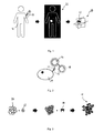
- FIG 1 is a schematic illustration of a corresponding procedure.
- Figure 1 shows a patient 10 to which a fluorescence marker 12 is administered by injection using a syringe 14.
- An example of a marker 12 that can be used for this purpose is shown in Figure 2 .
- the marker 12 comprises a radioactive tracer and a fluorescent dye 18, for example ICG.
- the radioactive tracer comprises chelator complex 16 with a radiometal such as 68 Ga, which is connected to the fluorescent dye via a linker. Both are connected to a binding motive 20 which binds with a PSMA enzyme 22 of a prostate cell 24. Accordingly, when the marker 12 is injected to the patient 10 as shown in Figure 1 , the marker 12 will bind with the PSMA enzyme 22.
- a medical image is taken, as indicated by reference sign 26.
- the medical image can for example be a combined PET-CT image which allows for obtaining a 3D image of the body using a CT scan, and in addition to detect the localization of the marker 12 by means of the radioactive tracer using the PET modality.
- a medical image 28 of the patient is obtained, which includes, in addition to the medical image proper, information regarding the spatial position of the fluorescence markers 12 within the body of the patient 10.
- This medical image 28 is an example of the "3D patient data set" referred to in the summary of the invention above.
- the medical image 28 is symbolically resembled by a corresponding coordinate system. Also included in the representation of the medical image is information about the spatial location of the markers 12, which for simplicity is designated by the same reference sign 12, although the skilled person will appreciate that this is not the actual, physical marker, but the representation of the marker in the medical image 28.
- FIG 3 schematically shows the construction of an alternative fluorescence marker 12 in a way similar to that described in van den Berg et al. "Fluorescence Guidarrce in urologic surgery", Current opinion in urology 22, 2; p. 109-120 (2012 ).
- the fluorescence marker 12 of Figure 3 consists of nano colloids 30 which are combined with a radio tracer 32, which in the example shown is formed by 99 Tc.
- a CT or MR imaging (MRI) contrast agents could be used instead.
- This combined nano colloid and radioactive tracer 30, 32 is then combined with a fluorescent dye 18, in the present example indocyanine green ICG, such as to form a nano particle complex of radio tracer and fluorescent dye.
- the location of the fluorescence marker 12 within the image can be discerned due to the radioactive tracer 30.
- the marker 12 upon injection, the marker 12 will not accumulate at a specific location, but a certain spatial distribution of fluorescence markers 12 within the body will nevertheless be obtained, and the information regarding the spatial position of the fluorescence markers 12 within the body can be obtained and included in or associated with the medical image 28.
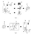
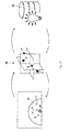
- Figure 4 symbolically represents a further scenario for administering fluorescence markers 12 and determining the position in the medical image 28.
- a mixture of a fluorescent dye 18 and a contrast agent 34 is given into a first barrel 36 of a double barrel syringe 38, and an adhesive 40 is given into a second barrel 40 of said double barrel syringe 38.
- a mixture of the fluorescent dye 18, contrast agent 34 and adhesive can be applied directly to a body part, such as an organ 44, as illustrated in the left part of Figure 4 . Localized spots of the mixture of fluorescent dye 18, contrast agent 34 and adhesive 40 can be regarded as "fluorescence markers" 12 in the sense of the present invention.
- the adhesive 40 is a biodegradable adhesive, such as a fibrin adhesive or cyanoacrylate.
- a medical image 28 of the body or body part including said fluorescence markers 12 is taken.
- this medical image can be taken using a conventional CT apparatus 46, or a so-called "Dyna CT” apparatus 48 comprising a C-shaped gantry.
- the "Dyna CT” apparatus 48 allows to take the medical image 28 not only pre-operatively, but also during the surgery.
- the fluorescent dye 18 is ICG
- some adhesives 40 such as cyanoacrylate tend to suppress the quenching effect thereof, which leads to a longer-lasting fluorescence.
- the fluorescence markers 12 can be applied preoperatively and still lead to sufficient fluorescence during surgery.
- the fluorescence markers consisting of ICG and cyanoacrylate show a stronger fluorescence signal as compared to the fluorescent dye in solution.
- the medical image 28 can also be obtained by 3D ultrasound imaging or photoacoustic tomography (PAT) imaging.
- PAT photoacoustic tomography
- Figure 4 where an ultrasound probe head 50 is schematically shown.
- ultrasound imaging it may be difficult to discern the fluorescence markers 12 in the image.
- photoacoustic tomography when choosing the photo acoustic wavelength properly, the fluorescence marker 12 can be directly detected or "seen" in the image.
- the starting point is a 3D medical image 28, which however does not yet include any information about spatial positions of fluorescence markers.
- This patient information is added to the medical image "manually", i.e. the surgeon may mark certain characteristic locations 52 in the medical image, as shown in the middle of Figure 5 .
- the "characteristic locations” are locations which the surgeon will also reliably find in the patient's actual body for manually applying markers 12 thereto, for example by again using an adhesive 40 and a fluorescent agent 18, but no contrast agent (see right part of Figure 5 ).
- the characteristic locations 52 could for example correspond to a branching point of a blood vessel 54 and a further position located a predetermined distance away from the branching point on a predetermined one of the branches of the blood vessel 54.
- the pattern of the distribution of the fluorescence markers 12 there are no limitations about the pattern of the distribution of the fluorescence markers 12, as long as the surgeon is able to determine precisely where these locations are both in the 3D medical image 28 and in the actual patient's body 10.
- This variant has the advantage that after placing the markers 12, no additional medical imaging step is necessary, does however require a certain amount of skill and experience of the surgeon.
- the system of the invention comprises an apparatus for detecting fluorescence from the fluorescence markers 12 provided in the patient's body 10. Examples of such apparatuses and methods for using the same will be illustrated with reference to Figures 6, 7 and 8 .
- Figure 6 shows a laparoscope 56 that can be used intraoperatively, as well as an organ 44 to which fluorescence markers 12 are attached.
- the laparoscope 56 has both, a visual image modality, as well as a fluorescence image modality.
- the laparoscope 56 has a light source (not shown) for illuminating the surgical site, such as the organ 44 with visual light, a light source (not shown) for emitting excitation light for exciting the fluorescent dye included in the fluorescence markers 12, as well as corresponding image sensors for recording video images of the visible light and the fluorescence light.
- the laparoscope 56 could have two different image sensors and a wavelength selective splitter, or could have a single image sensor and a switchable wavelength selective filter.
- Both, the visual image and the fluorescence image can then be displayed in an overlayed fashion on a display shown under the reference sign 58 in Figure 6 .
- the image of the organ 44 and the fluorescence markers 12 are designated with the same reference signs as the corresponding physical objects.
- the fluorescent dye included in the fluorescence marker 12 will emit in the NIR spectral range, which is almost not or not seen with an ordinary camera nor with the naked eye, but the fluorescence markers 12 can of course be visualized on the display 58 such as to be seen by the surgeon.
- the image sensor (not shown) for recording video images of the visible light, together with the display 58, forms an example of the "visualization tool" referred to in the summary of the invention.
- the image sensor (not shown) for recording fluorescence images forms an example of the "apparatus for detecting fluorescence" referred to in the summary of the invention.
- the fluorescence markers are not displayed on the display 58, but only used for registration purposes.
- Figure 7 shows again a patient's body 10 including a fluorescence marker 12. While reference is made to "the fluorescence marker 12" for simplicity, in actual examples there could be a fluorescent region in which functionalized markers such as the markers shown in Fig. 2 have accumulated in a target tissue. Further shown in Figure 7 are a light source 60 for emitting excitation light for exciting fluorescence of a fluorescent dye included in the fluorescence marker 12, and a light source 62 for visual light that illuminates the region of interest. This light source 62 could simply be the ordinary lighting system of the operating room. Further shown in Figure 7 is a fluorescence camera 64 for taking fluorescence images, typically IR images, and an ordinary RGB camera 66 for taking images in the visual spectrum.
- a fluorescence camera 64 for taking fluorescence images, typically IR images, and an ordinary RGB camera 66 for taking images in the visual spectrum.
- the fluorescence light is symbolized by a dashed ray, while the visible light is illustrated by a solid ray.
- a lens 68 is provided in the light path of both, the visible and the fluorescence light.
- a wavelength selective splitter 70 is provided for reflecting the visible light to the RGB camera 66 and for transmitting the IR light to the fluorescence camera 64.
- a wavelength selective splitter 70 a wavelength unselective half mirror could be used, and the fluorescence camera 64 and the RGB camera 66 could be provided with suitable filters transmitting only the desired component of the available light.
- a display 58 is shown on which the RGB image of the body and the fluorescence image of the fluorescence marker 12 (or tissue in which fluorescence markers 12 are accumulated) are superimposed.
- the RGB camera 66 together with the display 58, forms an example of the "visualization tool" referred to in the summary of the invention, while the fluorescence camera 64 resembles an example of an "apparatus for detecting fluorescence".
- Figure 8 shows a yet further embodiment, where the apparatus for detecting fluorescence is formed by glasses 72 shown in a top and a front view, respectively.
- a fluorescence camera 74 is provided which allows for taking fluorescence images of the fluorescence markers 12 distributed inside the patient's body 10 under surgery.
- a lens 76 of the glasses Through a lens 76 of the glasses, the user can get a direct view on the surgical site.
- additional graphical information can be projected into the field of view of the user. This additional graphical information could represent augmented reality to be described below, but also the fluorescence image detected by the fluorescence camera 74.
- the fluorescence image taken by the fluorescence camera 74 can be correlated with the field of view seen by the user wearing the glasses 72.
- the glasses 72 form a further example of a "visualization tool" as referred to in the summary of the invention, while the fluorescence camera 74 attached thereto forms a yet further example of the "apparatus for detecting fluorescence".
- the fluorescence camera 74 attached thereto forms a yet further example of the "apparatus for detecting fluorescence”.
- graphical information could alternatively be projected onto the patient's body.
- the fluorescence markers 12 are essentially point-like objects, in further embodiments the fluorescence markers can be used to mark surfaces, or surface parts, that can be surface registered. In addition, the registration need not exclusively rely on the fluorescence markers.
- the markers can be combined with surface registration, where a surface of the patient's body part is matched with a surface within the 3D data set.
- biomedical modelling algorithms can be employed for deformable registration, in which the point or surface correspondences serve as boundary conditions.
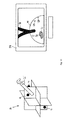
- Figure 9B shows a situation under surgery, where again an organ 44 provided with fluorescence markers 12 and a laparoscope 56 are shown.
- a fluorescence image can be recorded which includes the fluorescence image of the fluorescence markers 12, as shown in the left half of Figure 9A .
- This view of the fluorescence markers 12 can be correlated with the spatial distribution of fluorescence markers 12 in the medical image 28, schematically shown in the right half of Figure 9A .
- This correlation is symbolically represented by the double arrows associating the fluorescence image of the fluorescence markers 12 and the fluorescence marker 12 as included in the medical image 28.
- the laparoscope 56 has the capability of obtaining 3D information of the location of the fluorescence markers 12, for example by employing two cameras placed at a distance for obtaining stereo data, then this 3D information can be matched with the known 3D positions of the fluorescence markers 12 within the 3D medical image 28.
- the 3D medical image can be mapped into a coordinate system of the laparoscope 56, possibly accounting for deformation of non-rigid body parts, e.g. using a biomechanical model.
- Figure 10 shows in the left half the situation, where the position of the laparoscope 56 with regard to the patient body 12, or, in other words, the position of the virtual laparoscope 56' with regard to the medical image 28 has been derived.
- this augmentation amounts to displaying a blood vessel 78, which in the actual RGB image (see right half of Figure 6 ) cannot be seen, for example because it is covered by other tissue.
- the information that the blood vessel 78 is there is derived from the medical image 28 which includes the blood vessel 78.
- a further example of this type of "augmented reality" is a tumor 80, or what is believed to be at tumor based on the medical image 28.
- the surgeon can select features in the medical image 28 prior to or during the surgery that are to be projected into the image shown on display 58.
- the information derived from the medical image 28 can however not only be used to augment the view or image of the patient's body 10, but also to correct or improve an optical or medical image taking during surgery.
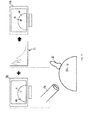
- An example for this is discussed with reference to Figure 11 .
- the fluorescence image may appear somewhat feeble, for example due to the fact that the corresponding fluorescence marker 12 is covered by tissue, such that a substantial part of the fluorescent light is absorbed and scattered thereby. Accordingly, there is some uncertainty whether actually a fluorescence marker 12 is detected, or whether there is an artifact.
- the thickness of the tissue covering the fluorescence marker 12 can be determined, and from this the expected absorption of fluorescence light can be estimated. This estimation can be made more precise if the absorbance of the tissue is accounted for, which can in many cases likewise be derived from the medical image 28.
- the medical image is, at least in part, obtained by photoacoustic tomography, which allows for deriving a characteristic absorption curve as shown at reference sign 81 in Figure 11 .
- a photoacoustic tomography probe head 82 is shown in the lower part of Figure 11 .
- the loss of intensity of the fluorescence light detected can be corrected, as is symbolically shown on the right of Figure 11 , where the brightness of the fluorescence image is correspondingly increased and a fluorescence marker can be identified indeed.
- absorption curve is obtained using photoacoustic tomography
- similar or related information can also be derived if other medical imaging modalities are used.
- the tissue composition can likewise be characterized, and the characteristic absorption can be estimated therefrom.
- the absorption properties are not only important for evaluating the fluorescence light from the fluorescence markers 12, but can also be used when multispectral or photoacoustic images are taken for diagnostic purposes.
- tissue properties from a pre-operatively taken 3D medical image
- the quality of a photoacoustic tomography image taken during surgery can be improved.
- the system of the invention may also operate the other way around in the sense that information gathered during surgery is associated with the three-dimensional medical image 28.
- the medical image 28, or more generally, the 3D patient data set can be enriched and be used for future scientific or educational purposes.
- Figure 12 which on the left shows an image taken during surgery, showing again the organ 44 and the fluorescence markers 12, and in the middle symbolically represents the medical image 28.
- the surgeon inputs a command that indicates to the system that the location 86 of a biopsy tool 84 used for this purpose should be recorded, and this location 86 may be labeled. Each of these labeled locations 86 can then be associated with the medical image 28, as is indicated in the middle of Figure 12 .
- the result thereof can likewise be associated with the labeled location 86 in the medical image 28.
- the medical image 28 enriched by this additional histologic information can then be stored in a database shown in the right of Figure 12 under reference sign 88. Then, anyone searching in the database 88 for certain histological findings can find corresponding medical images 28, and can thereby learn how this histology was manifested in the medical image. This way, doctors and algorithms can better learn how to interpret medical images 28.
- the system provides an interface allowing a user to input information associated with corresponding locations in the medical image 28.
Priority Applications (4)
| Application Number | Priority Date | Filing Date | Title |
|---|---|---|---|
| EP15193169.8A EP3165153A1 (fr) | 2015-11-05 | 2015-11-05 | Système de chirurgie assistée par fluorescence |
| EP16778003.0A EP3370599A1 (fr) | 2015-11-05 | 2016-10-06 | Système pour chirurgie assistée par fluorescence |
| PCT/EP2016/073856 WO2017076571A1 (fr) | 2015-11-05 | 2016-10-06 | Système pour chirurgie assistée par fluorescence |
| US15/773,627 US20190059736A1 (en) | 2015-11-05 | 2016-10-06 | System for Fluorescence Aided Surgery |
Applications Claiming Priority (1)
| Application Number | Priority Date | Filing Date | Title |
|---|---|---|---|
| EP15193169.8A EP3165153A1 (fr) | 2015-11-05 | 2015-11-05 | Système de chirurgie assistée par fluorescence |
Publications (1)
| Publication Number | Publication Date |
|---|---|
| EP3165153A1 true EP3165153A1 (fr) | 2017-05-10 |
Family
ID=54478598
Family Applications (2)
| Application Number | Title | Priority Date | Filing Date |
|---|---|---|---|
| EP15193169.8A Withdrawn EP3165153A1 (fr) | 2015-11-05 | 2015-11-05 | Système de chirurgie assistée par fluorescence |
| EP16778003.0A Pending EP3370599A1 (fr) | 2015-11-05 | 2016-10-06 | Système pour chirurgie assistée par fluorescence |
Family Applications After (1)
| Application Number | Title | Priority Date | Filing Date |
|---|---|---|---|
| EP16778003.0A Pending EP3370599A1 (fr) | 2015-11-05 | 2016-10-06 | Système pour chirurgie assistée par fluorescence |
Country Status (3)
| Country | Link |
|---|---|
| US (1) | US20190059736A1 (fr) |
| EP (2) | EP3165153A1 (fr) |
| WO (1) | WO2017076571A1 (fr) |
Cited By (4)
| Publication number | Priority date | Publication date | Assignee | Title |
|---|---|---|---|---|
| WO2019217893A1 (fr) * | 2018-05-10 | 2019-11-14 | Memorial Sloan Kettering Cancer Center | Systèmes de visualisation chirurgicale et clinique en réalité augmentée |
| US11282211B2 (en) | 2019-01-23 | 2022-03-22 | Siemens Healthcare Gmbh | Medical imaging device, method for supporting medical personnel, computer program product, and computer-readable storage medium |
| WO2023034598A1 (fr) * | 2021-09-02 | 2023-03-09 | Covidien Lp | Enregistrement en temps réel à l'aide d'une imagerie par fluorescence proche infrarouge |
| EP4169474A1 (fr) * | 2021-10-25 | 2023-04-26 | Erbe Vision GmbH | Système et procédé d'enregistrement d'images |
Families Citing this family (9)
| Publication number | Priority date | Publication date | Assignee | Title |
|---|---|---|---|---|
| US10925598B2 (en) | 2018-07-16 | 2021-02-23 | Ethicon Llc | Robotically-assisted surgical suturing systems |
| US20220095903A1 (en) * | 2019-01-25 | 2022-03-31 | Intuitive Surgical Operations, Inc. | Augmented medical vision systems and methods |
| US11759283B2 (en) | 2019-12-30 | 2023-09-19 | Cilag Gmbh International | Surgical systems for generating three dimensional constructs of anatomical organs and coupling identified anatomical structures thereto |
| US11896442B2 (en) | 2019-12-30 | 2024-02-13 | Cilag Gmbh International | Surgical systems for proposing and corroborating organ portion removals |
| US11776144B2 (en) | 2019-12-30 | 2023-10-03 | Cilag Gmbh International | System and method for determining, adjusting, and managing resection margin about a subject tissue |
| US11832996B2 (en) | 2019-12-30 | 2023-12-05 | Cilag Gmbh International | Analyzing surgical trends by a surgical system |
| US11744667B2 (en) | 2019-12-30 | 2023-09-05 | Cilag Gmbh International | Adaptive visualization by a surgical system |
| US11284963B2 (en) | 2019-12-30 | 2022-03-29 | Cilag Gmbh International | Method of using imaging devices in surgery |
| US11860098B1 (en) * | 2023-01-13 | 2024-01-02 | Tencent America LLC | Method and device for three-dimensional object scanning with invisible markers |
Citations (7)
| Publication number | Priority date | Publication date | Assignee | Title |
|---|---|---|---|---|
| US20130137873A1 (en) * | 2007-02-09 | 2013-05-30 | Nara Narayanan | Polycyclo Dyes and Use Thereof |
| WO2013158636A1 (fr) | 2012-04-16 | 2013-10-24 | Azizian Mahdi | Système bimode d'imagerie stéréo pour suivi et commande dans des interventions chirurgicales et des techniques interventionnelles |
| US20140028667A1 (en) * | 2012-07-30 | 2014-01-30 | Bernd Spruck | Three-Dimensional Representation of Objects |
| WO2014145606A1 (fr) | 2013-03-15 | 2014-09-18 | Sloan-Kettering Institute For Cancer Research | Nanoparticules multimodales à base de silice |
| US20140378843A1 (en) * | 2012-01-20 | 2014-12-25 | The Trustees Of Dartmouth College | Method And Apparatus For Quantitative Hyperspectral Fluorescence And Reflectance Imaging For Surgical Guidance |
| US20150073433A1 (en) * | 2011-01-24 | 2015-03-12 | Imris Inc. | MR Compatible Fluorescence Viewing Device for Use in the Bore of an MR Magnet |
| WO2015126466A1 (fr) * | 2014-02-21 | 2015-08-27 | The University Of Akron | Système d'imagerie et d'affichage permettant de guider des interventions médicales |
Family Cites Families (25)
| Publication number | Priority date | Publication date | Assignee | Title |
|---|---|---|---|---|
| WO2004081865A2 (fr) * | 2003-03-10 | 2004-09-23 | University Of Iowa Research Foundation | Systemes et procedes permettant de realiser une reconstruction tomographique calculee bioluminescente |
| US20090217932A1 (en) * | 2008-03-03 | 2009-09-03 | Ethicon Endo-Surgery, Inc. | Intraluminal tissue markers |
| US20100022893A1 (en) * | 2008-07-24 | 2010-01-28 | Hart Douglas P | Self-inflating bladder |
| WO2010019515A2 (fr) * | 2008-08-10 | 2010-02-18 | Board Of Regents, The University Of Texas System | Appareil d'imagerie hyperspectrale à traitement de lumière numérique |
| CN103209656B (zh) * | 2010-09-10 | 2015-11-25 | 约翰霍普金斯大学 | 配准过的表面下解剖部的可视化 |
| EP2452649A1 (fr) | 2010-11-12 | 2012-05-16 | Deutsches Krebsforschungszentrum Stiftung des Öffentlichen Rechts | Visualisation de données anatomiques à réalité améliorée |
| US20130023765A1 (en) * | 2011-01-05 | 2013-01-24 | The Regents Of The University Of California | Apparatus and method for quantitative noncontact in vivo fluorescence tomography using a priori information |
| EP3338617B1 (fr) * | 2012-01-23 | 2020-08-19 | Washington University | Systèmes et dispositifs d'imagerie par lunette |
| US20160038029A1 (en) * | 2013-03-15 | 2016-02-11 | Board Of Regents Of The University Of Texas System | System and method for fluorescence tomography |
| CA2894133C (fr) * | 2013-03-15 | 2016-11-01 | Synaptive Medical (Barbados) Inc. | Systemes d'imagerie chirurgicale |
| EP3087424A4 (fr) * | 2013-12-23 | 2017-09-27 | Camplex, Inc. | Systèmes de visualisation chirurgicale |
| US11547300B2 (en) * | 2014-01-31 | 2023-01-10 | The General Hospital Corporation | Methods of treating and imaging tumor micrometastases using photoactive immunoconjugates |
| US10152796B2 (en) * | 2014-02-24 | 2018-12-11 | H. Lee Moffitt Cancer Center And Research Institute, Inc. | Methods and systems for performing segmentation and registration of images using neutrosophic similarity scores |
| CA2949241A1 (fr) * | 2014-05-20 | 2015-11-26 | University Of Washington Through Its Center For Commercialization | Systemes et procedes de visualisation chirurgicale par realite induite |
| US10639104B1 (en) * | 2014-11-07 | 2020-05-05 | Verily Life Sciences Llc | Surgery guidance system |
| US10702353B2 (en) * | 2014-12-05 | 2020-07-07 | Camplex, Inc. | Surgical visualizations systems and displays |
| JP2016109579A (ja) * | 2014-12-08 | 2016-06-20 | ソニー株式会社 | 情報処理装置、画像取得システム、情報処理方法、画像情報取得方法及びプログラム |
| JP2018514748A (ja) * | 2015-02-06 | 2018-06-07 | ザ ユニバーシティ オブ アクロンThe University of Akron | 光学撮像システムおよびその方法 |
| KR101734094B1 (ko) * | 2015-03-09 | 2017-05-11 | 국립암센터 | 증강현실영상 투영 시스템 |
| US20160324580A1 (en) * | 2015-03-23 | 2016-11-10 | Justin Esterberg | Systems and methods for assisted surgical navigation |
| EP3277152A4 (fr) * | 2015-03-25 | 2018-12-26 | Camplex, Inc. | Systèmes et affichages de visualisation à usage chirurgical |
| US10598914B2 (en) * | 2015-07-14 | 2020-03-24 | Massachusetts Institute Of Technology | Enhancement of video-rate fluorescence imagery collected in the second near-infrared optical window |
| US20170046586A1 (en) * | 2015-08-10 | 2017-02-16 | Adnan Abbas | Optical projection overlay device |
| US11839433B2 (en) * | 2016-09-22 | 2023-12-12 | Medtronic Navigation, Inc. | System for guided procedures |
| WO2018097831A1 (fr) * | 2016-11-24 | 2018-05-31 | Smith Joshua R | Capture et restitution de champ lumineux pour des visiocasques |
-
2015
- 2015-11-05 EP EP15193169.8A patent/EP3165153A1/fr not_active Withdrawn
-
2016
- 2016-10-06 EP EP16778003.0A patent/EP3370599A1/fr active Pending
- 2016-10-06 US US15/773,627 patent/US20190059736A1/en not_active Abandoned
- 2016-10-06 WO PCT/EP2016/073856 patent/WO2017076571A1/fr active Application Filing
Patent Citations (7)
| Publication number | Priority date | Publication date | Assignee | Title |
|---|---|---|---|---|
| US20130137873A1 (en) * | 2007-02-09 | 2013-05-30 | Nara Narayanan | Polycyclo Dyes and Use Thereof |
| US20150073433A1 (en) * | 2011-01-24 | 2015-03-12 | Imris Inc. | MR Compatible Fluorescence Viewing Device for Use in the Bore of an MR Magnet |
| US20140378843A1 (en) * | 2012-01-20 | 2014-12-25 | The Trustees Of Dartmouth College | Method And Apparatus For Quantitative Hyperspectral Fluorescence And Reflectance Imaging For Surgical Guidance |
| WO2013158636A1 (fr) | 2012-04-16 | 2013-10-24 | Azizian Mahdi | Système bimode d'imagerie stéréo pour suivi et commande dans des interventions chirurgicales et des techniques interventionnelles |
| US20140028667A1 (en) * | 2012-07-30 | 2014-01-30 | Bernd Spruck | Three-Dimensional Representation of Objects |
| WO2014145606A1 (fr) | 2013-03-15 | 2014-09-18 | Sloan-Kettering Institute For Cancer Research | Nanoparticules multimodales à base de silice |
| WO2015126466A1 (fr) * | 2014-02-21 | 2015-08-27 | The University Of Akron | Système d'imagerie et d'affichage permettant de guider des interventions médicales |
Non-Patent Citations (5)
| Title |
|---|
| BAUMHAUER: "Soft tissue navigation for laparoscopic partical nephrectomy", INT J CARS, vol. 3, no. 3, 2008, pages 307 - 314 |
| MAIER-HEIN ET AL.: "Optical techniques for 3d surface reconstruction in computer-assisted laparoscopic surgery", MEDICAL IMAGE ANALYSIS, vol. 17, no. 8, 2013, pages 974 - 966, XP055249579, DOI: doi:10.1016/j.media.2013.04.003 |
| MAIER-HEIN, L; TEKBAS, A; SEITEL, A; PIANKA, F; MÜLLER, SA; SATZL, S; SCHAWO, S; RADELEFF, B; TETZLAFF, R; FRANZ, AM: "In-vivo accuracy assessment of a needle-based navigation system for CT-guided radiofrequency ablation of the liver", MED PHYS, vol. 35, no. 12, 2008, pages 5385 - 5396, XP012115833, DOI: doi:10.1118/1.3002315 |
| MIILLER, M ET AL.: "Mobile augmented reality for computer-assisted percutaneous nephrolithotomy", INT J CARS, vol. 8, no. 4, 2013, pages 663 - 675, XP055085869, DOI: doi:10.1007/s11548-013-0828-4 |
| VAN DEN BERG ET AL.: "Fluorescence Guidance in urologic surgery", CURRENT OPINION IN UROLOGY, vol. 22, no. 2, 2012, pages 109 - 120 |
Cited By (5)
| Publication number | Priority date | Publication date | Assignee | Title |
|---|---|---|---|---|
| WO2019217893A1 (fr) * | 2018-05-10 | 2019-11-14 | Memorial Sloan Kettering Cancer Center | Systèmes de visualisation chirurgicale et clinique en réalité augmentée |
| US11666411B2 (en) | 2018-05-10 | 2023-06-06 | Memorial Sloan Kettering Cancer Center | Systems for augmented reality surgical and clinical visualization |
| US11282211B2 (en) | 2019-01-23 | 2022-03-22 | Siemens Healthcare Gmbh | Medical imaging device, method for supporting medical personnel, computer program product, and computer-readable storage medium |
| WO2023034598A1 (fr) * | 2021-09-02 | 2023-03-09 | Covidien Lp | Enregistrement en temps réel à l'aide d'une imagerie par fluorescence proche infrarouge |
| EP4169474A1 (fr) * | 2021-10-25 | 2023-04-26 | Erbe Vision GmbH | Système et procédé d'enregistrement d'images |
Also Published As
| Publication number | Publication date |
|---|---|
| US20190059736A1 (en) | 2019-02-28 |
| WO2017076571A1 (fr) | 2017-05-11 |
| EP3370599A1 (fr) | 2018-09-12 |
Similar Documents
| Publication | Publication Date | Title |
|---|---|---|
| US20190059736A1 (en) | System for Fluorescence Aided Surgery | |
| Brouwer et al. | Image navigation as a means to expand the boundaries of fluorescence-guided surgery | |
| US11871913B2 (en) | Computed tomography enhanced fluoroscopic system, device, and method of utilizing the same | |
| US10758209B2 (en) | Photoacoustic tracking and registration in interventional ultrasound | |
| US11304686B2 (en) | System and method for guided injection during endoscopic surgery | |
| CN108140242A (zh) | 视频摄像机与医学成像的配准 | |
| US20200195903A1 (en) | Systems and methods for imaging a patient | |
| Wild et al. | Robust augmented reality guidance with fluorescent markers in laparoscopic surgery | |
| KR20130015146A (ko) | 의료 영상 처리 방법 및 장치, 영상 유도를 이용한 로봇 수술 시스템 | |
| KR20150001756A (ko) | 수술 및 중재 시술에서 추적 및 제어를 위한 듀얼-모드 스테레오 이미징 시스템 | |
| Azagury et al. | Image-guided surgery | |
| Greco et al. | Current perspectives in the use of molecular imaging to target surgical treatments for genitourinary cancers | |
| Okur et al. | MR in OR: First analysis of AR/VR visualization in 100 intra-operative Freehand SPECT acquisitions | |
| US11571180B2 (en) | Systems providing images guiding surgery | |
| JP2022512333A (ja) | 医療用撮像データを表示するためのシステム及び方法 | |
| Mitchell et al. | Image-guided surgery and emerging molecular imaging: advances to complement minimally invasive surgery | |
| WO2018109227A1 (fr) | Système fournissant des images guidant une chirurgie | |
| Vijayalakshmi | Image-guided surgery through internet of things | |
| Shahin et al. | Ultrasound-based tumor movement compensation during navigated laparoscopic liver interventions | |
| Han et al. | Imaging techniques for minimally invasive thoracic surgery—Korea University Guro Hospital experiences | |
| Quang | Integrated intraoperative imaging and navigation system for computer-assisted interventions | |
| Kim et al. | Integrating FireFly fluorescence into image guidance for the da Vinci robot | |
| US20220414994A1 (en) | Representation apparatus for displaying a graphical representation of an augmented reality | |
| KR100941612B1 (ko) | 골 종양 수술에서의 내비게이션 방법 | |
| Liu | Intraoperative Imaging and Navigation in Robotic Surgery |
Legal Events
| Date | Code | Title | Description |
|---|---|---|---|
| PUAI | Public reference made under article 153(3) epc to a published international application that has entered the european phase |
Free format text: ORIGINAL CODE: 0009012 |
|
| STAA | Information on the status of an ep patent application or granted ep patent |
Free format text: STATUS: THE APPLICATION HAS BEEN PUBLISHED |
|
| AK | Designated contracting states |
Kind code of ref document: A1 Designated state(s): AL AT BE BG CH CY CZ DE DK EE ES FI FR GB GR HR HU IE IS IT LI LT LU LV MC MK MT NL NO PL PT RO RS SE SI SK SM TR |
|
| AX | Request for extension of the european patent |
Extension state: BA ME |
|
| STAA | Information on the status of an ep patent application or granted ep patent |
Free format text: STATUS: THE APPLICATION IS DEEMED TO BE WITHDRAWN |
|
| 18D | Application deemed to be withdrawn |
Effective date: 20171111 |