EP3333603B1 - Holographisches optisches element und herstellungsverfahren dafür - Google Patents
Holographisches optisches element und herstellungsverfahren dafür Download PDFInfo
- Publication number
- EP3333603B1 EP3333603B1 EP16832709.6A EP16832709A EP3333603B1 EP 3333603 B1 EP3333603 B1 EP 3333603B1 EP 16832709 A EP16832709 A EP 16832709A EP 3333603 B1 EP3333603 B1 EP 3333603B1
- Authority
- EP
- European Patent Office
- Prior art keywords
- layer
- adjacent layer
- mass
- thiol compound
- holographic optical
- Prior art date
- Legal status (The legal status is an assumption and is not a legal conclusion. Google has not performed a legal analysis and makes no representation as to the accuracy of the status listed.)
- Active
Links
Images


Classifications
-
- G—PHYSICS
- G11—INFORMATION STORAGE
- G11B—INFORMATION STORAGE BASED ON RELATIVE MOVEMENT BETWEEN RECORD CARRIER AND TRANSDUCER
- G11B7/00—Recording or reproducing by optical means, e.g. recording using a thermal beam of optical radiation by modifying optical properties or the physical structure, reproducing using an optical beam at lower power by sensing optical properties; Record carriers therefor
- G11B7/24—Record carriers characterised by shape, structure or physical properties, or by the selection of the material
- G11B7/2403—Layers; Shape, structure or physical properties thereof
- G11B7/24035—Recording layers
- G11B7/24044—Recording layers for storing optical interference patterns, e.g. holograms; for storing data in three dimensions [3D], e.g. volume storage
-
- G—PHYSICS
- G02—OPTICS
- G02B—OPTICAL ELEMENTS, SYSTEMS OR APPARATUS
- G02B5/00—Optical elements other than lenses
- G02B5/32—Holograms used as optical elements
-
- C—CHEMISTRY; METALLURGY
- C08—ORGANIC MACROMOLECULAR COMPOUNDS; THEIR PREPARATION OR CHEMICAL WORKING-UP; COMPOSITIONS BASED THEREON
- C08K—Use of inorganic or non-macromolecular organic substances as compounding ingredients
- C08K5/00—Use of organic ingredients
- C08K5/36—Sulfur-, selenium-, or tellurium-containing compounds
- C08K5/37—Thiols
-
- C—CHEMISTRY; METALLURGY
- C08—ORGANIC MACROMOLECULAR COMPOUNDS; THEIR PREPARATION OR CHEMICAL WORKING-UP; COMPOSITIONS BASED THEREON
- C08K—Use of inorganic or non-macromolecular organic substances as compounding ingredients
- C08K5/00—Use of organic ingredients
- C08K5/36—Sulfur-, selenium-, or tellurium-containing compounds
- C08K5/37—Thiols
- C08K5/378—Thiols containing heterocyclic rings
-
- G—PHYSICS
- G03—PHOTOGRAPHY; CINEMATOGRAPHY; ANALOGOUS TECHNIQUES USING WAVES OTHER THAN OPTICAL WAVES; ELECTROGRAPHY; HOLOGRAPHY
- G03H—HOLOGRAPHIC PROCESSES OR APPARATUS
- G03H1/00—Holographic processes or apparatus using light, infrared or ultraviolet waves for obtaining holograms or for obtaining an image from them; Details peculiar thereto
- G03H1/02—Details of features involved during the holographic process; Replication of holograms without interference recording
-
- G—PHYSICS
- G03—PHOTOGRAPHY; CINEMATOGRAPHY; ANALOGOUS TECHNIQUES USING WAVES OTHER THAN OPTICAL WAVES; ELECTROGRAPHY; HOLOGRAPHY
- G03H—HOLOGRAPHIC PROCESSES OR APPARATUS
- G03H1/00—Holographic processes or apparatus using light, infrared or ultraviolet waves for obtaining holograms or for obtaining an image from them; Details peculiar thereto
- G03H1/02—Details of features involved during the holographic process; Replication of holograms without interference recording
- G03H1/024—Hologram nature or properties
- G03H1/0248—Volume holograms
-
- G—PHYSICS
- G03—PHOTOGRAPHY; CINEMATOGRAPHY; ANALOGOUS TECHNIQUES USING WAVES OTHER THAN OPTICAL WAVES; ELECTROGRAPHY; HOLOGRAPHY
- G03H—HOLOGRAPHIC PROCESSES OR APPARATUS
- G03H1/00—Holographic processes or apparatus using light, infrared or ultraviolet waves for obtaining holograms or for obtaining an image from them; Details peculiar thereto
- G03H1/04—Processes or apparatus for producing holograms
-
- G—PHYSICS
- G03—PHOTOGRAPHY; CINEMATOGRAPHY; ANALOGOUS TECHNIQUES USING WAVES OTHER THAN OPTICAL WAVES; ELECTROGRAPHY; HOLOGRAPHY
- G03H—HOLOGRAPHIC PROCESSES OR APPARATUS
- G03H1/00—Holographic processes or apparatus using light, infrared or ultraviolet waves for obtaining holograms or for obtaining an image from them; Details peculiar thereto
- G03H1/04—Processes or apparatus for producing holograms
- G03H1/0402—Recording geometries or arrangements
-
- G—PHYSICS
- G02—OPTICS
- G02B—OPTICAL ELEMENTS, SYSTEMS OR APPARATUS
- G02B27/00—Optical systems or apparatus not provided for by any of the groups G02B1/00 - G02B26/00, G02B30/00
- G02B27/01—Head-up displays
-
- G—PHYSICS
- G02—OPTICS
- G02B—OPTICAL ELEMENTS, SYSTEMS OR APPARATUS
- G02B27/00—Optical systems or apparatus not provided for by any of the groups G02B1/00 - G02B26/00, G02B30/00
- G02B27/02—Viewing or reading apparatus
-
- G—PHYSICS
- G03—PHOTOGRAPHY; CINEMATOGRAPHY; ANALOGOUS TECHNIQUES USING WAVES OTHER THAN OPTICAL WAVES; ELECTROGRAPHY; HOLOGRAPHY
- G03H—HOLOGRAPHIC PROCESSES OR APPARATUS
- G03H1/00—Holographic processes or apparatus using light, infrared or ultraviolet waves for obtaining holograms or for obtaining an image from them; Details peculiar thereto
- G03H1/04—Processes or apparatus for producing holograms
- G03H1/0402—Recording geometries or arrangements
- G03H2001/0439—Recording geometries or arrangements for recording Holographic Optical Element [HOE]
-
- G—PHYSICS
- G03—PHOTOGRAPHY; CINEMATOGRAPHY; ANALOGOUS TECHNIQUES USING WAVES OTHER THAN OPTICAL WAVES; ELECTROGRAPHY; HOLOGRAPHY
- G03H—HOLOGRAPHIC PROCESSES OR APPARATUS
- G03H2260/00—Recording materials or recording processes
- G03H2260/12—Photopolymer
Definitions
- the present invention relates to a holographic optical element and a method for producing the same.
- a holographic optical element having a volume hologram recording layer functions as an optical combiner and is applied to an optical lens, a display element and the like, and its demand is increasing.
- the holographic optical element as a display element of a head mount display or a head up display has high transparency of the volume hologram recording layer and thus can be used as a see-through type display element (for example, JP 2014-215410 A ).
- JPH 06-301322 A discloses a photosensitive composition excellent in refractive index modulation and a method for producing a volume hologram recording layer using the photosensitive composition. More specifically, according to JPH 06-301322 A , a volume hologram recording layer is prepared by subjecting a photosensitive layer obtained by applying and drying a photosensitive composition containing a polymerizable monomer sandwiched between a pair of transparent supports to face-to-face exposure with a coherent light source (interference exposure), causing a polymerization reaction in accordance with the interference wave in the photosensitive layer, and forming a diffraction grating composed of regions of high refractive index and low refractive index.
- a volume hologram recording layer is prepared by subjecting a photosensitive layer obtained by applying and drying a photosensitive composition containing a polymerizable monomer sandwiched between a pair of transparent supports to face-to-face exposure with a coherent light source (interference exposure), causing a polymerization reaction in accordance with the interference wave
- JP 2014-44242 A proposes a technique in which a compound containing two or more thiol groups is added to the composition for forming a photosensitive layer, in addition to the photopolymerizable monomer or the like.
- the demand for a holographic optical element has increased, the demand for its quality is also increasing.
- a technique capable of enhancing the diffraction efficiency which is the basic characteristic of the volume hologram recording layer, has been required.
- the holographic optical element is required to maintain its quality for a long period regardless of the variation in use environment.
- an object of the present invention to provide a means for improving the diffraction efficiency of a holographic optical element having a volume hologram recording layer. Also, another object of the present invention is to provide a means for improving the durability of the holographic optical element.
- the present inventors have conducted intensive study. As a result, the present inventors have found that the above problem can be solved by a holographic optical element containing a thiol compound in an adjacent layer provided in contact with a volume hologram recording layer, and have completed the present invention.
- a holographic optical element having a volume hologram recording layer containing a photopolymer, and at least one adjacent layer which is in contact with the volume hologram recording layer and contains a resin and a thiol compound.
- a method for producing a holographic optical element including: forming a photosensitive layer comprising a polymerizable monomer so that the photosensitive layer is in contact with an adjacent layer comprising a resin and a thiol compound, and then subjecting the photosensitive layer to holographic exposure to form a volume hologram recording layer.
- a layer containing a polymerizable monomer before holographic exposure is referred to as a photosensitive layer
- a layer in which a volume hologram is recorded by subjecting the photosensitive layer to holographic exposure is referred to as a volume hologram recording layer.
- the holographic optical element of the present embodiment has a volume hologram recording layer containing a photopolymer, and at least one adjacent layer which is in contact with the volume hologram recording layer and contains a resin and a thiol compound.
- the holographic optical element of the present embodiment having such a configuration is excellent in diffraction efficiency.
- a diffraction grating having a high refractive index region and a low refractive index region is formed in the volume hologram recording layer because the following phenomena occur in the photosensitive layer. That is, when holographic exposure is performed and polymerization of the polymerizable monomer in the photosensitive layer is promoted in the exposed part, diffusion movement of the polymerizable monomer occurs so as to minimize the interface between the polymerizable monomer and other components, and also the polymerization reaction further proceeds. As a result, in the photosensitive layer, the photopolymer region formed by the polymerization reaction and the other component region are formed as the same pattern as the interference wave irradiated by holographic exposure.
- the formation of a diffraction grating near the interface between the volume hologram recording layer and the adjacent layer is also presumed to be a major factor.
- the thiol compound contained in the adjacent layer functions like a so-called radical chain transfer agent.
- the frequency of chain transfer of radical polymerization near the interface with the adjacent layer is increased in the volume hologram recording layer, and the polymerization of the polymerizable monomer is promoted.
- the polymerization of the polymerizable monomer is easy to proceed toward the interface with the adjacent layer, and the formation of diffraction grating is promoted.
- the diffraction grating formation at the interface of the adjacent layer is performed sufficiently (surely), high diffraction efficiency can be achieved.
- JP 2014-44242 A proposes a technique relating to a volume hologram recording body mainly used for security purposes, and discloses a composition containing a thiol compound as a composition for forming a photosensitive layer of the recording body.
- a composition containing a thiol compound as a composition for forming a photosensitive layer of the recording body.
- the thiol compound is uniformly dispersed in the photosensitive layer which is formed by the composition containing the thiol compound, polymerization of the present polymerizable monomer may proceed in all directions within the exposed range.
- JP 2014-44242 A does not describe that a thiol compound is contained in the substrate side.
- JP 2014-44242 A the form in which a thiol compound is contained only in the photosensitive layer is less likely to obtain the effect of promoting polymerization in the vicinity of the interface with the adjacent layer, as compared with the present embodiment. Therefore, even if the technique of JP 2014-44242 A is adopted for a holographic optical element used for optical element applications, it is difficult to form a diffraction grating up to the vicinity of the interface with the adjacent layer, so the diffraction efficiency is not sufficient, and it is presumed that there is still room for improvement from the viewpoint of improving image quality.
- the present inventors have found that the holographic optical element according to the present embodiment is also excellent in durability in the process of examining the improvement of the diffraction efficiency as described above.
- one of the causes is diffusion movement of the polymerizable monomer or polymer (photopolymer) in the photosensitive layer. Such a diffusion movement phenomenon lowers the adhesion of the interface between the adjacent layer and the volume hologram recording layer (photosensitive layer).
- the holographic optical element of the present embodiment it is considered that polymerization of the polymerizable monomer is promoted at the interface between the photosensitive layer and the adjacent layer, as described above. Therefore, the diffraction grating surely formed up to the vicinity of the interface can enhance the adhesion between the adjacent layer and the volume hologram recording layer. Thereby, the holographic optical element of the present embodiment exhibits excellent durability such that peeling between the volume hologram recording layer and the adjacent layer is not likely to occur over a long term, and high diffraction efficiency can be maintained for a long period of time.
- a means for improving the diffraction efficiency of a holographic optical element having a volume hologram recording layer is provided. Further, according to the present invention, a means for improving the durability of the holographic optical element is provided.
- the "(from) X to Y" indicating the range means “X or more and Y or less", including X and Y.
- the operations and the measurements of physical properties are conducted under the conditions of room temperature (20 to 25°C)/relative humidity of 40 to 50% RH.
- Fig. 1 is a schematic cross-sectional view showing a typical configuration of a holographic optical element of the present embodiment.
- the holographic optical element 10 includes a volume hologram recording layer 11 and a pair of adjacent layers 12.
- a pair of adjacent layers 12 is provided so as to be in contact with both surfaces of the volume hologram recording layer 11, but the adjacent layer 12 may be provided only on one side of the volume hologram recording layer 11.
- the adjacent layer of the holographic optical element of the present embodiment contains a resin as a base material and a thiol compound.
- a thiol compound When forming a photopolymer contained in the volume hologram recording layer, such a thiol compound can exert a function like a chain transfer agent for radical polymerization.
- the thiol compound moves in the adjacent layer, in conjunction with the diffusion movement phenomenon of the polymerizable monomer, the photopolymer or the like in the photosensitive layer, and promotes formation of the diffraction grating near the interface with the adjacent layer, in the photosensitive layer.
- the thiol compound contained in the adjacent layer can improve the diffraction efficiency by the mechanism as described above, and furthermore, an effect that peeling between the volume hologram recording layer and the adjacent layer is not likely to occur over a long term and thus the holographic optical element is excellent in durability can also be obtained.
- the adjacent layer having the above configuration may be provided so as to be in contact with both surfaces of the volume hologram recording layer or may be provided so as to be in contact with only one side. That is, the holographic optical element of the present embodiment may have at least one adjacent layer containing a resin and a thiol compound, which is in contact with the volume hologram recording layer.
- the constituent material and thickness of each adjacent layer may be the same or different.
- a known resin having transparency can be used as the resin contained in an adjacent layer.
- resins include acrylic resins, polycarbonate, polyethylene terephthalate, polybutylene terephthalate, polyethylene naphthoate, polyethylene, polypropylene, amorphous polyolefin, cellulose acetate, hydrated cellulose, cellulose nitrate, cycloolefin polymers, polystyrene, polyepoxide, polysulfone, cellulose acylate, polyamide, polyimide, polystyrene, polymethyl methacrylate, polyvinyl chloride, polyvinyl butyral, polydicyclopentane diene, and the like.
- the amount of the resin in an adjacent layer is preferably 70% by mass or more.
- the upper limit is not particularly limited, but is preferably 99.999% by mass or less, more preferably 99.995% by mass or less, and particularly preferably 99.5% by mass or less.
- polyethylene terephthalate, cycloolefin polymer, cellulose acylate and polymethyl methacrylate are preferable.
- cellulose acylate has a density at which a thiol compound easily moves in the adjacent layer, and has a high surface energy that can have an affinity with a thiol group (-SH) of a thiol compound. Therefore, cellulose acylate is more preferable from the viewpoint of easily contributing to the improvement of diffraction efficiency and durability.
- the cellulose acylate is a polymer obtained by acylating a part or all of these hydroxy groups with an acyl group.
- the degree of substitution of an acyl group is the sum of the proportions of cellulose esterified at 2, 3 and 6 positions of the repeating unit. Specifically, the degree of substitution is 1 when each of the hydroxy groups at 2, 3 and 6 positions of cellulose is esterified to 100%. Therefore, when all of 2, 3 and 6 positions of cellulose are esterified to 100%, the degree of substitution becomes 3 at maximum.
- the degree of substitution of an acyl group can be measured according to ASTM-D817-96.
- the degree of substitution of the acyl group is preferably from 1.80 to 2.68 and more preferably from 2.40 to 2.65, from the viewpoint of the density of an adjacent layer.
- acyl group examples include an acetyl group, an n-propionyl group, an isopropionyl group, an n-butanoyl group, an isobutanoyl group, a t-butanoyl group, a pentanoyl group, a hexanoyl group, a heptanoyl group, an octanoyl group, a decanoyl group, a dodecanoyl group, a tridecanoyl group, a tetradecanoyl group, a hexadecanoyl group, an octadecanoyl group, a cyclohexanecarbonyl group, an oleoyl group, a benzoyl group, a naphthylcarbonyl group, a cinnamoyl group, or aromatic acyl groups represented by the following general formula (I), and the like.
- X represents a methyl group, an ethyl group, an n-propyl group, an isopropyl group, an n-butyl group, an isobutyl group, a t-butyl group, a pentyl group, a hexyl group, a heptyl group or an octyl group, n is an integer of 1 to 5, and when n is 2 or more, a plurality of Xs may be linked to each other to form a ring.
- an acetyl group, an n-propionyl group, an n-butanoyl group, a t-butanoyl group, a dodecanoyl group, an octadecanoyl group, an oleoyl group, a benzoyl group, a naphthylcarbonyl group, a cinnamoyl group, aromatic acyl groups represented by the above general formula (I) are more preferable, an acetyl group, an n-propionyl group, an n-butanoyl group, a t-butanoyl group, a benzoyl group and aromatic acyl groups represented by the above general formula (I) are further preferable, and an acetyl group is particularly preferable.
- the degree of substitution of an acetyl group of cellulose acylate is preferably 1.80 to 2.68, and more preferably 2.40 to 2.65.
- the weight average molecular weight (Mw) of cellulose acylate is preferably in the range of 75000 to 280000 and more preferably in the range of 100000 to 240000, from the viewpoint of securing uniformity of optical properties and ensuring productivity and processability.
- the weight average molecular weight (Mw) of cellulose acylate can be measured using gel permeation chromatography (GPC) under the following measurement conditions.
- the amount of cellulose acylate in the adjacent layer is preferably 99.999% by mass or less, more preferably from 70 to 99.995% by mass, and particularly preferably from 70 to 99.5% by mass,relative to the total mass of the adjacent layer.
- An adjacent layer of the present embodiment contains a thiol compound together with the above resin.
- the thiol compound is not particularly limited as long as it has at least one thiol group (-SH).
- the thiol compound can act as a chain transfer agent for radical polymerization of a polymerizable monomer. Such a thiol compound promotes the polymerization of the polymerizable monomer to the interface with the adjacent layer at the time of forming the volume hologram recording layer and promotes the formation of diffraction grating. As a result, a holographic optical element having excellent diffraction efficiency can be fabricated.
- the molecular weight of the thiol compound used in the present embodiment is not particularly limited, but it is preferably 80 to 330.
- the molecular weight of the thiol compound is preferably 80 to 330.
- the molecular weight of the thiol compound is more preferably from 100 to 250, and particularly preferably from 110 to 230.
- any compound having a thiol group can be used without particular limitation.
- Specific examples of the compound include the following compounds.
- thiol groups such as alkane thiol compounds such as ethyl mercaptan, n-butyl mercaptan, t-butyl mercaptan, 1-dodecyl mercaptan (n-dodecanethiol), and 1-octadecanethiol; heterocyclic mercaptans such as 3-mercapto-1,2,4-triazole, 4-methyl-4H-1,2,4-triazole-3-thiol, 3-amino-5-mercapto-1,2,4-triazole, 4-amino-3-hydrazino-5-mercapto-1,2,4-triazole, 4-cyclohexyl-5-mercapto-4H-1,2,4-triazol-3-ol; 2-mercaptooxazole; 2-mercaptobenzoxazole; 2-mercaptothiazole; 2-mercaptobenzothiazole, 5-chloro
- trifunctional thiol compound such as heterocyclic mercaptans such as 2,4,6-trimercapto-s-triazine and 2,4,6-trimercapto-1,3,5-triazine; and ester compounds of a trihydric alcohol and mercaptocarboxylic acid such as trimethylolethane tris(3-mercaptobutyrate) and trimethylolpropane tris(3-mercaptobutyrate).
- the thiol compound may be a polyfunctional thiol compound having four or more thiol groups. Also, these thiol compounds can be used singly or in combination of two or more kinds.
- the thiol compound is preferably a mercaptan having a heterocyclic ring (heterocyclic mercaptan compound).
- the heterocyclic ring represents a monocyclic heterocyclic ring composed of a 5-membered ring or 6-membered ring containing 1 to 4 hetero atoms selected from the group consisting of a nitrogen atom, an oxygen atom and a sulfur atom, or a polycyclic fused heterocyclic ring having two or more rings.
- Such mercaptans tend to have high compatibility with the resin forming the adjacent layer and to have excellent transfer capability in the adjacent layer. Therefore, the effect of polymerization promotion near the interface with the adjacent layer is improved.
- those having a triazole skeleton, a benzoxazole skeleton or a benzothiazole skeleton are preferable. Since these compounds have particularly high compatibility with the resin forming the adjacent layer and have excellent transfer capability in the adjacent layer, polymerization promotion at the interface with the adjacent layer becomes favorable, and the diffraction efficiency and its durability are further improved. From the above viewpoint, it is further preferable that the thiol compound has a benzoxazole skeleton or a benzothiazole skeleton.
- the resin contained in the adjacent layer contains polyethylene terephthalate, a cycloolefin polymer, cellulose acylate or polymethyl methacrylate and the thiol compound contained in the adjacent layer has a triazole skeleton, a benzoxazole skeleton or a benzothiazole skeleton.
- the thiol compound is contained in the adjacent layer, and it is preferably at least present near the interface with the volume hologram recording layer. More specifically, in the adjacent layer, it is preferable that the thiol compound is contained in the region which has a thickness of at least up to 100 nm from the interface between the adjacent layer and the volume hologram recording layer (herein sometimes referred to as "region A").
- region A the region which has a thickness of at least up to 100 nm from the interface between the adjacent layer and the volume hologram recording layer.
- the mass ratio (content ratio; C 2 in the Examples) of the thiol compound to the total mass of the adjacent layer occupying the range (region A) is preferably within a specific range.
- the content ratio (C 2 ) of the thiol compound in the region A is preferably 0.001 to 3.5% by mass, more preferably 0.005 to 3.5% by mass, still more preferably 0.005 to 3.2% by mass, and particularly preferably 0.005% by mass or more and less than 3.1% by mass.
- the content ratio (C 2 ) of the thiol compound in the region A By setting the content ratio (C 2 ) of the thiol compound in the region A to 0.001% by mass or more, and further 0.005% by mass or more, the polymerization of the polymerizable monomer near the interface with the adjacent layer in the volume hologram recording layer is sufficiently promoted, which contributes to further improvement of diffraction efficiency.
- the content ratio (C 2 ) of the thiol compound in the region A is 3.5% by mass or less, further 3.2% by mass or less, and further less than 3.1% by mass, peeling between the volume hologram recording layer and the adjacent layer is less likely to occur, which is preferable in that durability is improved.
- durability can also be improved.
- the content ratio (C 2 ) of the thiol compound in the region A is still more preferably 0.005 to 3.0% by mass, still more preferably 0.005 to 2.9% by mass, particularly more preferably 0.01 to 2.9% by mass, and most preferably 0.03 to 1.5% by mass.
- the content ratio (C 2 ) of the thiol compound in the region A is measured by the method described in the Examples. Also, when two or more kinds of thiol compounds are contained, the content ratio (C 2 ) is calculated based on the total mass.
- the mass ratio (content ratio; C 1 in the Examples) of the thiol compound to the mass of the entire adjacent layer is not particularly limited, but is preferably 0.000001 to 3.5% by mass, more preferably 0.00001% by mass or more and less than 3.1% by mass, still more preferably 0.001 to 2.9% by mass, still more preferably 0.005 to 2.9% by mass, particularly preferably 0.01 to 2.9% by mass, and most preferably 0.01 to 1.5% by mass.
- the content ratio (C 1 ) of the thiol compound to the mass of the entire adjacent layer is measured by the method described in the Examples. Also, when two or more kinds of thiol compounds are contained, the content ratio (C 1 ) is calculated based on the total mass.
- the adjacent layer preferably contains a thiol compound in the region A, and may be, for example, a form in which a thiol compound is unevenly distributed in the adjacent layer (form (i)), or a form in which a thiol compound is contained over the entire adjacent layer (form (ii)).
- the form (i) is a form in which a first layer containing at least a resin and a thiol compound and a second layer not containing thiol compound but containing at least a resin are laminated to form an adjacent layer.
- the adjacent layer of the form (i) may be formed not only by laminating the first layer and the second layer one by one, but also the first layer and/or the second layer may be composed of a plurality of layers.
- the first layer is composed of a plurality of layers
- the thiol compounds and the resins contained in the respective layers may be the same or different.
- the resins contained in the respective layers may be the same or different.
- the adjacent layer of the form (ii) is a form in which the thiol compound and the resin are substantially uniformly dispersed in the layer.
- a form (film) can be formed by employing a known method or appropriately modifying the known method.
- the effect of improving the diffraction efficiency can be obtained, and further, the effect of improving the durability can be sufficiently obtained.
- the thickness of the adjacent layer is not particularly limited, but is preferably 10 to 1000 ⁇ m, and more preferably 50 to 200 ⁇ m.
- the "thickness of the adjacent layer" in the above embodiment (i) refers to the total thickness of the first layer and the second layer.
- the adjacent layer in the form of a film has been described, but the adjacent layer may be in the form of a layer such as a film or plate or may be a substrate form also serving as a prism.
- the adjacent layer is in the form of a layer, processing by cutting is possible, and there is the convenience that it can be adopted to various optical elements.
- the method for forming an adjacent layer into the form of a layer such as a film or the like is not particularly limited, and any conventionally known method such as a melt extrusion method, a solution casting method, a calendar method or a compression molding method can be used. Among these methods, a melt extrusion method and a solution casting method are preferable.
- the melt extrusion method includes a method in which a resin, a thiol compound, and other components added as necessary are melt-kneaded and then formed into a film by melt extrusion.
- a kneader used for kneading is not particularly limited, and for example, a conventionally known kneading machine such as an extruder such as a single screw extruder or a twin screw extruder or a pressure kneader can be used.
- the melt extrusion method for forming into a film includes a T-die method, an inflation method, and the like.
- the molding temperature at the time of melt extrusion varies depending on the type of the resin, so it cannot be said definitely, but it is preferably from 200 to 350°C.
- a T-die is attached at the tip of a known single screw extruder or twin screw extruder to wind a film extruded into a film, whereby a roll-shaped film can be obtained.
- a T-die for a single layer as shown in Fig. 2 as the T-die to be used it is possible to easily form the adjacent layer of the form (ii).
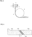
- the adjacent layer of the form (i) it can be easily formed by using a co-extrusion T-die as shown in Fig. 3 .
- an adjacent layer composition (composition for the first layer) containing a resin, a thiol compound, and other components added as necessary may be introduced into one pocket of the co-extrusion T-die, and the other adjacent layer composition (composition for the second layer) containing no thiol compound and containing at least a resin may be introduced into the other pocket.
- each of the first layer and/or the second layer is composed of a plurality of layers
- the solution casting method includes a method of preparing a solution or dispersion (dope) containing a resin, a thiol compound, and other components added as necessary, and then casting the solution or dispersion, and the like.
- the solvent used for the solution casting method is not particularly limited, and examples thereof include chlorine-based solvents such as chloroform and methylene chloride; aromatic solvents such as toluene, xylene, benzene, and mixtures thereof; alcohol solvents such as methanol, ethanol, n-propanol, 2-propanol, n-butanol, sec-butanol, t-butanol, 2,2,2-trifluoroethanol, 2,2,3,3-tetrafluoro-1-propanol, 1,3-difluoro-2-propanol, 1,1,1,3,3,3-hexafluoro-2-methyl-2-propanol,1,1,1,3,3,3-hexafluoro-2-propanol, and 2,2,3,3,3-pentafluoro-1-propanol; methylcellosolve, ethylcellosolve, butylcellosolve, dimethylformamide, dimethylsulfoxide, 1,3-
- a film is preferably formed by a method including a step of casting the dope onto the above apparatus, a step of drying the cast dope as a web, a step of peeling the web from the apparatus after drying, a step of holding the web in the stretching or width direction, a step of further drying the web and the like, whereby an adjacent layer is formed.
- the adjacent layer of the above (i) it is preferable to perform a step of casting a first dope (the adjacent layer composition containing a resin, a thiol compound and a solvent, and other components added as necessary) on an apparatus and drying the first dope, then a step of casting a second dope (other adjacent layer composition containing no thiol compound and containing at least a resin and a solvent) on the first dope and drying the second dope to form a web, a step of peeling the web from the apparatus after drying, a step of holding the web in the stretching or width direction, a step of further drying the web, and the like.
- a first dope the adjacent layer composition containing a resin, a thiol compound and a solvent, and other components added as necessary
- a second dope other adjacent layer composition containing no thiol compound and containing at least a resin and a solvent
- each of the first layer and/or the second layer is composed of a plurality of layers
- a plurality of first and/or second dope is prepared corresponding to the layer constitution, and the above steps may be repeated as appropriate so as to laminate these layers.
- an injection molding method can be used as a method for forming the adjacent layer into a substrate form. Preparation of the substrate by injection molding is carried out by melt kneading of the adjacent layer component, injection from the kneader into a mold, cooling with the mold and removal of the substrate.
- melt kneading of the resin and other components a conventionally known kneader such as an extruder such as a single screw extruder, a twin screw extruder or a pressure kneader can be used. At that time, in order to secure uniformity of the kneaded material, it is preferable to conduct melt-kneading while heating at a temperature higher than the glass transition temperature (Tg) of the resin.
- Tg glass transition temperature
- the injection amount can be adjusted by the amount of pressurization from the kneader to the mold, the diameter of the inner which becomes the path of the kneaded material to the mold and the applied temperature to the inner, and the like.
- the temperature of the mold during the injection of the kneaded material is preferably set to be equal to or lower than the Tg of the resin. As a result, dimensional accuracy can be ensured.
- the preferable cooling temperature is in the range of Tg or lower to Tg - 100°C, still preferably in the range of Tg or lower to Tg - 50°C, and further preferably in the range of Tg or lower to Tg - 20°C.
- the volume hologram recording layer is prepared by at least subjecting holographic exposure to a coating film (photosensitive layer) obtained by applying a photosensitive composition containing a polymerizable monomer, and a photopolymerization initiator and a matrix resin or a precursor thereof added as necessary to the adjacent layer described above and drying it, to form a diffraction grating composed of a high refractive index region and a low refractive index region in the photosensitive layer.
- the volume hologram recording layer contains a photopolymer.
- the "photopolymer” herein refers to a polymer obtained as a result of polymerization of the polymerizable monomer contained in the photosensitive composition described above.
- the photosensitive composition used for forming the volume hologram recording layer may contain, in addition to the radical polymerizable monomer, a photopolymerization initiator, a matrix resin or a precursor thereof, a sensitizer, a chain transfer agent, a solvent, and the like.
- these components will be described.
- radical polymerizable monomer those having a relatively high refractive index are preferable, and examples thereof include acrylamide, methacrylamide, methylenebisacrylamide, polyethylene glycol diacrylate, trimethylolpropane triacrylate, pentaerythritol triacrylate, dipentaerythritol hexaacrylate, 2,3-dibromopropyl acrylate, dicyclopentanyl acrylate, dibromoneopentyl glycol diacrylate, 2-phenoxyethyl acrylate, 2-phenoxymethyl methacrylate, phenol ethoxylate monoacrylate, 2-(p-chlorophenoxy)ethyl acrylate, p-chlorophenyl acrylate, phenyl acrylate, 2-phenylethyl acrylate, 2-(1-naphthyloxy)ethyl acrylate, o-biphenyl methacrylate, o-biphenyl methacryl
- examples thereof include those having a 9,9-diarylfluorene skeleton and having at least one ethylenically unsaturated bond in the molecule. Specifically, it is a compound having the following structure.
- R 1 and R 2 are each independently a radically polymerizable group having an acryloyl group or a methacryloyl group at the terminal.
- a preferred embodiment is a group having an acryloyl group or a methacryloyl group at the terminal and capable of bonding to the benzene ring of the above-described compound, via an oxyethylene chain, an oxypropylene chain, a urethane bond, an amide bond, or the like.
- X 1 to X 4 are each independently a hydrogen atom or a substituent.
- substituents include alkyl groups having 1 to 4 carbon atoms, alkoxy groups having 1 to 4 carbon atoms, amino groups, dialkylamino groups, hydroxyl groups, carboxyl groups, halogen atoms, and the like.
- a urethane acrylate comprising a condensation product of a phenyl isocyanate compound and a compound having a hydroxy group and an ethylenically unsaturated bond such as an acryloyl group in one molecule can also be used. Specifically, it is a compound having the following structure.
- Rs are each independently a group having an ethylenically unsaturated bond
- Xs are each independently a single bond, an oxygen atom, or a linear, branched or cyclic divalent aliphatic hydrocarbon group.
- a compound having a structure represented by the following chemical formula (IV) can also be used.
- R 1 to R 5 are each independently a hydrogen atom, a halogen atom, an alkyl group having 1 to 6 carbon atoms, a trifluoromethyl group, an alkylthio group having 1 to 6 carbon atoms, an alkylseleno group having 1 to 6 carbon atoms, an alkyltelluro group having 1 to 6 carbon atoms or a nitro group, and R 6 and R 7 are each independently a hydrogen atom or an alkyl group having 1 to 6 carbon atoms.
- A is a linear or branched alkylene group having 1 to 6 carbon atoms, a linear or branched alkenylene group having 2 to 6 carbon atoms, or a polyalkylene oxide group having an ethylene oxide unit or propylene oxide unit having 2 to 6 carbon atoms.
- R 1 to R 5 are each independently a hydrogen atom or an alkylthio group having 1 to 6 carbon atoms
- R 6 and R 7 are hydrogen atoms
- A is a linear or branched alkylene group having 2 to 6 carbon atoms.
- radical polymerizable monomers a monomer having a substituted or unsubstituted phenyl group, a monomer having a substituted or unsubstituted naphthyl group, a monomer having a substituted or unsubstituted heterocyclic aromatic moiety having up to 3 rings, a monomer having a chlorine atom and a monomer having a bromine atom are preferable because of their relatively high refractive index.
- radical polymerizable monomers can be used singly or in combination of two or more kinds.
- the amount of the radical polymerizable monomer in the photosensitive composition is preferably from 1 to 25% by mass, and more preferably from 5 to 20% by mass, relative to the total amount of the photosensitive composition.
- the radical polymerization initiator is an agent which initiates photopolymerization of the radical polymerizable monomer by irradiation with laser light having a specific wavelength or light having excellent coherence in holographic exposure.
- photo-radical polymerization initiators that can be used for such reactions, for example, known polymerization initiators described in US 4,766,055 , US 4,868,092 and US 4,965,171 , JP S54-151024 A , JP S58-15503 A , JP S58-29803 A , JP 59-189340 A , JP 60-76735 A , JP H1-28715 A and JP H4-239505 A , " PROCEEDINGS OF CONFERENCE ON RADIATION CURING ASIA" (pp. 461-477, 1988 ) and the like can be used, but are not limited thereto.
- photo-radical polymerization initiator examples include diaryl iodonium salts, 2,4,6-substituted-1,3,5-triazines (triazine compounds), azo compounds, azide compounds, organic peroxides, organic borates, onium salts, halogenated hydrocarbon derivatives, titanocene compounds, monoacylphosphine oxides, bisacylphosphine oxides, combinations of bisacylphosphine oxides and ⁇ -hydroxyketones, and the like.
- a photo-radical polymerization initiator system based on a combined use of a hydrogen donor such as a thiol compound and a bisimidazole derivative can be utilized.
- These photo-radical polymerization initiators may be used singly or in combination of two or more kinds.
- the amount of the photo-radical polymerization initiator to be used is preferably 0.05 to 50 parts by mass, and more preferably 0.1 to 30 parts by mass, relative to 100 parts by mass of the radical polymerizable monomer.
- the photosensitive composition may contain a sensitizer having a sensitizing function for a photo-radical polymerization initiator.
- a sensitizer has an absorption maximum wavelength in the range of 400 to 800 nm, especially 450 to 700 nm. These sensitizers absorb the light within the above-mentioned range, whereby sensitizing action occurs on the photo-radical polymerization initiator.
- sensitizers examples include polymethine-based compounds such as cyanine-based dyes and styryl-based dyes, xanthene-based compounds such as rhodamine B, rhodamine 6G and pyronin GY, phenazine-based compounds such as safranin O, phenoxazine-based compounds such as cresyl violet and brilliant cresylblue, phenothiazine-based compounds such as methylene blue and new methylene blue, diarylmethane-based compounds such as auramine, triarylmethane-based compounds such as crystal violet, brilliant green and Lissamine Green, (thio)pyrylium salt-based compounds, squarylium-based compounds, coumarin-based dyes, thioxanthene-based dyes, acene-based dyes, merocyanine-based dyes, thiazolium-based dyes, and the like. These sensitizers can be used sing
- the amount used is preferably from 1 to 2,000 parts by mass, and more preferably from 20 to 1,500 parts by mass, relative to 100 parts by mass of the photo-radical polymerization initiator.
- the photosensitive composition may contain a chain transfer agent.
- the chain transfer agent is not particularly limited, and a known radical chain transfer agent can be used.
- chain transfer agent examples include n-butyl mercaptan, t-butyl mercaptan, t-dodecyl mercaptan, n-octyl mercaptan, n-lauryl mercaptan, 5-chloro-2-mercaptobenzothiazole, 4-methyl-4H-1,2,4-triazole-3-thiol, 6-ethoxy-2-mercaptobenzothiazole and the like, as well as mercaptans such as the thiol compounds mentioned in the above section of ⁇ Thiol Compound>; disulfides such as tetramethylthiuram disulfide and tetraethylthiuram disulfide; halogen compounds such as carbon tetrachloride and carbon tetrabromide; olefins such as 2-methyl-1-butene and ⁇ -methylstyrene dimer; and the like. These chain transfer agents can be used singly
- the amount used is preferably from 0.05 to 50 parts by mass, and more preferably from 0.1 to 30 parts by mass, relative to 100 parts by mass of the radical polymerizable monomer.
- the matrix resin functions to improve the uniformity of film thickness of the volume hologram recording layer, heat resistance, mechanical properties and the like, and to stabilize the hologram formed by holographic exposure. Further, at the time of forming the volume hologram recording layer, the matrix resin can have a function of not inhibiting the diffusion movement phenomenon of the polymerizable monomer and the photopolymer or efficiently expressing the diffusion movement phenomenon.
- the matrix resin for example, a thermoplastic resin, a thermosetting resin, an active energy ray-curable resin and the like can be used without limitation.
- resins obtained by modifyng these resins with polysiloxane chains or perfluoroalkylene chains, and the like can also be used.
- the matrix resin can be used singly or in combination of two or more kinds.
- thermoplastic resin examples include, for example, polyvinyl acetate, polyvinyl butyrate, polyvinyl formal, polyvinyl carbazole, polyacrylic acid, polymethacrylic acid, polymethyl acrylate, polymethyl methacrylate, polyethyl acrylate, polybutyl acrylate, polymethacrylonitrile, polyethyl methacrylate, polybutyl methacrylate, polyacrylonitrile, poly-1,2-dichloroethylene, an ethylene-vinyl acetate copolymer, a tetrafluoroethylene-vinyl acetate copolymer, syndiotactic-type polymethyl methacrylate, poly- ⁇ -vinyl naphthalate, polycarbonate, cellulose acetate, cellulose triacetate, cellulose acetate butyrate, polystyrene, poly- ⁇ -methylstyrene, poly-o-methylstyrene, poly-p-methylstyren
- thermosetting resin examples include unsaturated polyester, acrylic urethane resin, epoxy-modified acrylic resin, epoxy-modified unsaturated polyester, polyurethane, alkyd resin, phenolic resin, and the like.
- the active energy ray-curable resin examples include epoxy acrylate, urethane acrylate, acryl-modified polyester, and the like.
- these active energy ray-curable resins can contain other monofunctional or polyfunctional monomers, oligomers and the like, as described below.
- the monofunctional monomer or oligomer is a mono(meth)acrylate such as tetrahydrofurfuryl (meth)acrylate, hydroxyethyl (meth)acrylate, (meth)acryloyloxyethyl succinate or (meth)acryloyloxyethyl phthalate, vinyl pyrrolidone.
- the polyfunctional monomer or oligomer is, when classified by skeleton structure, polyol (meth)acrylate (epoxy-modified polyol (meth)acrylate, lactone-modified polyol (meth)acrylate, etc.), polyester(meth)acrylate, epoxy (meth)acrylate, urethane (meth)acrylate, as well as poly (meth)acrylate having a skeleton such as polybutadiene type, isocyanuric acid type, hydantoin type, melamine type, phosphoric acid type, imide type or phosphazene type.
- Various monomer, oligomer and polymer which are curable by ultraviolet or electron beam can be used as the polyfunctional monomer or oligomer.
- thermoplastic resin thermosetting resin or active energy ray-curable resin
- a metal soap such as cobalt naphthenate or zinc naphthenate
- an organic peroxide such as benzoyl peroxide or methyl ethyl ketone peroxide
- a heat or active energy ray curing agent such as benzophenone, acetophenone, anthraquinone, naphthoquinone, azobisisobutyronitrile or diphenyl sulfide
- benzophenone acetophenone
- anthraquinone anthraquinone
- naphthoquinone azobisisobutyronitrile
- diphenyl sulfide can be contained in the photosensitive composition.
- thermosetting resin or an active energy ray-curable resin When a thermosetting resin or an active energy ray-curable resin is used, a photosensitive layer containing an uncured resin is formed on the adjacent layer and then, the uncured resin can be cured by heating or irradiation with an active energy ray. The curing may be carried out before or after the holographic exposure.
- a matrix resin precursor may be used.
- the precursor include isocyanate compounds and polyol compounds which form polyurethane by addition polymerization.
- the isocyanate compound is preferably one having two or more isocyanate groups in one molecule, but the type thereof is not particularly limited. When the number of isocyanate groups in one molecule is small, the required hardness as a matrix resin may not be obtained in some cases.
- the upper limit of the number of isocyanate groups in one molecule is not particularly limited, and is usually about 20 or less, preferably 8 or less, and further preferably 4 or less.
- the type is not particular limited as long as it has two or more isocyanate groups in one molecule.
- isocyanate compound used in the present embodiment examples include aliphatic isocyanates such as hexamethylene diisocyanate, lysine methyl ester diisocyanate and 2,4,4-trimethylhexamethylene diisocyanate, alicyclic isocyanates such as isophorone diisocyanate and 4,4'-methylenebis(cyclohexyl isocyanate); aromatic isocyanates such as tolylene diisocyanate, 4,4'-diphenylmethane diisocyanate, xylylene diisocyanate and naphthalene-1,5'-diisocyanate; multimers thereof or derivatives thereof, and the like.
- aliphatic isocyanates such as hexamethylene diisocyanate, lysine methyl ester diisocyanate and 2,4,4-trimethylhexamethylene diisocyanate
- alicyclic isocyanates such as isophorone diisocyanate and 4,4'-
- examples include reactants of water or a polyhydric alcohol such as trimethylolethane or trimethylolpropane with the isocyanate compound, and the like.
- polyol compound examples include polypropylene polyol, polycaprolactone polyol, polyester polyol, polycarbonate polyol, ethylene glycol, propylene glycol, 1,4-butanediol, 1,5-pentanediol, 3-methyl-1,5-pentanediol, 1,6-hexanediol, neopentyl glycol, diethylene glycol, 1,4-cyclohexanediol, 1,4-cyclohexanedimethanol, decamethylene glycol, trimethylolpropane, polyethylene glycol, polypropylene glycol, polytetramethylene glycol, and the like.
- These polyol compounds may be used singly or in combination of two or more kinds.
- a catalyst for addition polymerization of an isocyanate compound and a polyol compound can be blended in the photosensitive composition. Although these compounds can be cured at room temperature by using a catalyst, they may be cured by heating. The temperature during curing is preferably in the range of 40 to 90°C, and the curing time is preferably 1 to 24 hours.
- the catalyst examples include ordinary urethanation reaction catalysts such as tin compounds such as dibutyltin dilaurate, dioctyltin dilaurate and dibutyltin dioctanate, and tertiary amine compounds such as triethylamine and triethylenediamine.
- tin compounds such as dibutyltin dilaurate, dioctyltin dilaurate and dibutyltin dioctanate
- tertiary amine compounds such as triethylamine and triethylenediamine.
- the tin compound has good solubility and performance as a medium, and in particular, dibutyltin dilaurate is preferable.
- the amount of the catalyst to be used is preferably 0.0001% by mass or more, and more preferably 0.001% by mass or more, and is preferably 10% by mass or less, and more preferably 5% by mass or less, relative to the total amount of the isocyanate compound and the polyol compound.
- these catalysts are used, from the viewpoint of securing uniformity of the coating film of the photosensitive layer, it is preferable to add the catalyst to the photosensitive composition within 10 minutes before applying the photosensitive composition on the adjacent layer.
- a cationic polymerizable monomer may be used as another precursor of the matrix resin.
- the matrix resin obtained from the cationic polymerizable monomer makes it possible to form a volume hologram recording layer having excellent film strength.
- cationic polymerizable monomers include diglycerol polyglycidyl ether, pentaerythritol polyglycidyl ether, 1,4-bis(2,3-epoxypropoxyperfluoroisopropyl)cyclohexane, sorbitol polyglycidyl ether, trimethylolpropane polyglycidyl ether, resorcin diglycidyl ether, 1,6-hexanediol diglycidyl ether, polyethylene glycol diglycidyl ether, phenyl glycidyl ether, para-t-butylphenyl glycidyl ether, diglycidyl adipate, diglycidyl orthophthalate, dibromophenyl glycidyl ether, dibromoneopentyl glycol diglycidyl ether, 1,2,7,8-diepoxy octane, 1,6-di
- a photo cationic polymerization initiator or a thermal cationic polymerization initiator may be used.
- the photo-cationic polymerization initiator include iodonium salts, triarylsulfonium salts, and the like.
- Specific examples of the iodonium salts include tetrafluoroborate, hexafluorophosphate, hexafluoroarsenate, hexafluoroantimonate, trifluoromethanesulfonate, 9,10-dimethoxyanthracene-2-sulfonate of iodonium, and the like.
- triarylsulfonium salts include tetrafluoroborates of sulfonium such as triarylsulfonium, triphenylsulfonium, 4-t-butyltriphenylsulfonium, tris(4-methylphenyl)sulfonium, tris(4-methoxyphenyl)sulfonium and 4-thiophenyltriphenylsulfonium, hexafluorophosphate, hexafluoroarsenate, hexafluoroantimonate, trifluoromethanesulfonate, 9,10-dimethoxyanthracene-2-sulfonate of sulfonium, and the like.
- photo-cationic polymerization initiators can be used singly or in combination of two or more kinds.
- thermal cationic polymerization initiator examples include cationic or protonic acid catalysts such as triflic acid salt (triflate), boron trifluoride etherate complex and boron trifluoride, and preferable thermal cationic polymerization initiators is triflate.
- triflate examples include diethylammonium triflate available as "FC-520" from 3M Company, triethylammonium triflate, diisopropylammonium triflate, ethyldiisopropylammonium triflate and the like (many of which are described in Modern Coatings published by R.R.Alm in October 1980 ).
- aromatic onium salts also used as an active energy ray cationic polymerization initiator
- these can also be used as thermal cationic polymerization initiators.
- thermal cationic polymerization initiators examples include “San-Aid (registered trademark) SI-60L”, “San-Aid (registered trademark) SI-80L” and “San-Aid (registered trademark) SI-100L” (all manufactured by SANSHIN CHEMICAL INDUSTRY CO., LTD.).
- the amount of the photo-cationic polymerization initiator or the thermal cationic polymerization initiator to be used is preferably 0.05 to 50 parts by mass, and more preferably 0.1 to 30 parts by mass, relative to 100 parts by mass of the cationic polymerizable monomer.
- the amount of the matrix resin or its precursor in the photosensitive composition is preferably from 1 to 30% by mass, more preferably from 1 to 28% by mass, and further preferably from 5 to 27% by mass, relative to the total mass of the photosensitive composition.
- a solvent may be used as required at the time of coating.
- a solvent may not be required in some cases.
- the solvent examples include aliphatic solvents such as n-pentane, n-hexane, n-heptane, n-octane, cyclohexane and methylcyclohexane; ketone solvents such as methyl ethyl ketone (2-butanone), acetone and cyclohexanone; ether solvents such as diethyl ether, isopropyl ether, tetrahydrofuran, dioxane, ethylene glycol dimethyl ether, ethylene glycol diethyl ether, diethylene glycol dimethyl ether, diethylene glycol diethyl ether, propylene glycol monomethyl ether, anisole and phenetol; ester solvents such as ethyl acetate, butyl acetate and ethylene glycol diacetate; aromatic solvents such as toluene and xylene; cellosolve solvents such as methyl cellosolve,
- the photosensitive composition may further contain, if necessary, additives such as a plasticizer, a compatibilizer, a polymerization inhibitor, a surfactant, a silane coupling agent, a defoaming agent, a release agent, a stabilizer, an antioxidant, a flame retardant, an optical brightener and an ultraviolet absorber.
- additives such as a plasticizer, a compatibilizer, a polymerization inhibitor, a surfactant, a silane coupling agent, a defoaming agent, a release agent, a stabilizer, an antioxidant, a flame retardant, an optical brightener and an ultraviolet absorber.
- the photosensitive composition can be obtained by collectively or sequentially mixing the above-described components.
- Examples of an apparatus used for mixing include stirring or mixing apparatuses such as a magnetic stirrer, a homodisper, a quick homomixer, and a planetary mixer.
- the resulting photosensitive composition may be used after filtration, if necessary.
- the method for producing the holographic optical element is not particularly limited, and examples thereof include a production method including forming a photosensitive layer containing a polymerizable monomer so that the photosensitive layer is in contact with an adjacent layer containing a resin and a thiol compound, and subjecting the photosensitive layer to holographic exposure to form a volume hologram recording layer.
- the adjacent layer after the volume hologram recording layer is formed preferably contains a thiol compound, in the region whose distance is 100 nm or less from the interface between the volume hologram recording layer (photosensitive layer) and the adjacent layer (region A).
- the content ratio of the thiol compound in the region A is preferably 0.001 to 3.5% by mass, more preferably 0.005 to 3.5% by mass, still more preferably 0.005 to 3.2% by mass, and particularly preferably 0.005% by mass or more and less than 3.1% by mass.
- the method for forming a photosensitive layer on the adjacent layer is not particularly limited, and examples thereof include a method in which a photosensitive composition is directly applied on the adjacent layer and dried, a method in which a photosensitive composition is applied onto a separately prepared substrate and dried, followed by sticking the substrate to the adjacent layer using a laminator or the like and then peeling the substrate, and the like.
- a photosensitive layer is more likely to adhere to the adjacent layer and the combination with the adjacent layer promotes the formation of the diffraction grating to the interface with the adjacent layer inside the photosensitive layer, it is preferable to form a photosensitive layer by directly applying a photosensitive composition on the adjacent layer and drying it.
- the substrate examples include resin substrates containing acryl, polycarbonate, polyethylene terephthalate, polybutylene terephthalate, polyethylene naphthoate, polyethylene, polypropylene, amorphous polyolefin, cellulose acetate, hydrated cellulose, cellulose nitrate, cycloolefin polymers, polystyrene, polyepoxide, polysulfone, cellulose acylate, polyamide, polyimide, polymethyl methacrylate, polyvinyl chloride, polyvinyl butyral, polydicyclopentane diene, or the like.
- a method of applying the photosensitive composition on the adjacent layer or on the substrate conventionally known methods can be used, and specific examples include a spray method, a spin coating method, a wire bar method, a dip coating method, an air knife coating method, a roll coating method, a blade coating method, a doctor roll coating method, and the like.
- the drying various conventionally known methods using a hot plate, an oven, a belt furnace or the like can be adopted.
- the drying temperature is not particularly limited and is, for example, in the range of 10 to 80°C
- the drying time is not also particularly limited, and is, for example, in the range of 1 to 60 minutes.
- the thickness of the photosensitive layer may be appropriately set so that the volume hologram recording layer can be formed within the range of the preferable thickness described later.
- a photosensitive layer is formed on the adjacent layer, and the adjacent layer and the photosensitive layer are bonded to each other and then subjected to holographic exposure, whereby the polymerization reaction of the polymerizable monomer in the photosensitive layer proceeds.
- the photo-cured photopolymer region and the other component region generated by the polymerization reaction are formed as the same pattern as the interference wave irradiated by holographic exposure.
- the holographic optical element of the present embodiment has a structure in which the volume hologram recording layer is sandwiched between two adjacent layers, a photosensitive layer is formed on one adjacent layer, then another adjacent layer is laminated on the photosensitive layer using a laminator or the like, whereby a holographic optical element having the above-mentioned structure can be obtained.
- the method of subjecting the photosensitive layer to holographic exposure to record (write) a volume hologram to form into a volume hologram recording layer, and the method of reproducing (reading) the volume hologram are not particularly limited, and examples thereof include the following method.
- recording light also called as object light.
- the object light is emitted on the photosensitive layer together with the reference light so that the object light and the reference light interfere with each other in the photosensitive layer.
- the interference light causes polymerization and concentration changes of the polymerizable monomer in the photosensitive layer, and as a result, the interference fringe causes a difference in refractive index in the photosensitive layer.
- the difference in refractive index is recorded as a volume hologram due to the interference fringe recorded in the photosensitive layer, and it becomes a volume hologram recording layer. Thereby, a holographic optical element can be obtained.
- a visible light laser having excellent coherence As the recording light used for recording the volume hologram (indicating the wavelength in parentheses).
- a visible light laser having excellent coherence
- an argon ion laser (458 nm, 488 nm, 514 nm)
- a krypton ion laser 647.1 nm
- a helium-neon laser (633 nm)
- a YAG laser (532 nm) or the like can be used.
- the irradiation energy amount (exposure amount) at the time of hologram recording is not particularly limited, but it is preferably in the range of 10 to 250 mJ/cm 2 .
- the hologram recording method there are a polarized collinear hologram recording method, a multiple incident angle of reference light hologram recording method and the like, but it is possible to provide good recording quality in any recording method.
- the exposure apparatus is not particularly limited, but for example, an exposure apparatus of a type whose schematic configuration is shown in Fig. 5 can be used.
- a light beam (recording light) emitted from a laser light source 201 guides a light beam to an appropriate position of the exposure system by beam steerers 202a and 202b composed of two pairs of mirrors.
- Reference numeral 203 denotes a shutter, which controls ON/OFF of a light beam (recording light).
- Reference numeral 204 denotes a beam expander, which has a function of widening the light flux diameter and changing the numerical aperture (NA) according to the exposure area of the photosensitive layer.
- NA numerical aperture
- the light beam (recording light) that has passed through the beam expander 204 is divided into two light fluxes by beam splitter 205.
- the divided light beams (recording light) are guided to the spatial filters 211 and 212 by mirrors 206 and 207 and mirrors 209 and 208, respectively.
- the spatial filters 211 and 212 are composed of a lens and a pinhole, and the light beam (recording light) is condensed by the lens and the light beam (recording light) is guided to manufacturing optical system 213 via the pinhole.
- the manufacturing optical system 213 can set and fix a sample such as a glass prism having a photosensitive layer to be a volume hologram recording layer at a suitable position so that the reflection angle of light beam of the holographic optical element can be controlled.
- the photosensitive layer provided in a prism or the like fixed to the manufacturing optical system 213 is subjected to holographic exposure (interference exposure) by light beams (recording light) divided into two light fluxes, and respectively guided through the spatial filters 211 and 212.
- a chroic mirror is inserted in the optical path before the shutter 203, and laser beams emitted from a plurality of light sources may be synthesized step by step.
- processing such as entire exposure with ultraviolet rays and heating can be further appropriately performed on the volume hologram recording layer, in order to promote refractive index modulation and completion of the polymerization reaction (fixation).
- a light source used for entire exposure for example, a light source emitting ultraviolet rays such as an ultra-high pressure mercury lamp, a high pressure mercury lamp, a carbon arc lamp, a xenon arc lamp or a metal halide lamp can be used.
- the irradiation energy amount is preferably 50 to 200 J/cm 2 .
- the temperature when performing the heat treatment is preferably 50 to 150°C, and the treatment time is preferably 30 minutes to 3 hours.
- the order is not particularly limited, and the entire surface exposure may be performed first, or the heat treatment may be performed first.
- the thickness of the volume hologram recording layer (photosensitive layer) is preferably 10 to 100 ⁇ m, and more preferably 20 to 50 ⁇ m, from the viewpoint of durability.
- a predetermined reproducing light (usually reference light) is emitted to the volume hologram recording layer.
- the emitted reproducing light diffracts depending on the interference fringes. Since this diffracted light contains information similar to that of the volume hologram recording layer, information recorded on the volume hologram recording layer can be reproduced by reading the above-mentioned diffracted light by an appropriate detecting means.
- the wavelength regions of the object light, the reproducing light and the reference light are arbitrary according to their use, and may be a visible light region or an ultraviolet light region.
- the holographic optical element of the present embodiment may have other layers such as a protective layer, a reflective layer, an antireflection film, and an ultraviolet absorbing layer.
- the protective layer is a layer for preventing the influence such as degradation of storage stability of the recording layer.
- the specific constitution of the protective layer there is no limitation on the specific constitution of the protective layer, and a known one can be arbitrarily applied.
- a layer made of a water-soluble polymer, an organic/inorganic material or the like can be formed as a protective layer.
- the formation position of the protective layer is not particularly limited and may be formed, for example, on the surface of the volume hologram recording layer, between the adjacent layer and a support, or on the outer surface side of the support.
- the reflective layer is formed when the holographic optical element is configured as a reflection type.
- the reflective layer is usually formed on the outer surface of the adjacent layer.
- the reflective layer a conventionally known one can be appropriately referred to and applied, and for example, a metal thin film or the like can be used.
- the antireflection film may be provided also in either of the transmission type and reflection type holographic optical elements, on the side where the object light and the reproducing light enter and exit, or between the volume hologram recording layer and the adjacent layer.
- the antireflection film functions to improve the light utilization efficiency and to suppress the generation of the ghost image.
- As the antireflection film a conventionally known one can be appropriately referred to and applied.
- the holographic optical element of the present embodiment may be further sandwiched by a transparent support.
- the support may be adopted for protecting and holding the holographic optical element of the present embodiment, or it may be adopted to function as an optical element such as a prism in complex with the holographic optical element.
- the support is not particularly limited as long as it has necessary strength and durability, and any support can be used.
- the shape of the support is also not limited, but it is usually formed into a flat plate shape or a film shape.
- the material of the support is also not limited, and it may be transparent or opaque.
- Examples of transparent materials for the support include inorganic materials such as glass, silicon and quartz. Among these, glass is preferred.
- opaque materials for the support include metals such as aluminum; transparent supports coated with a metal such as gold, silver or aluminum, or a dielectric such as magnesium fluoride or zirconium oxide; and the like.
- Surface treatment may be applied to the surface of the support. This surface treatment is usually carried out to improve the adhesion between the support and the holographic optical element.
- Examples of the surface treatment include corona discharge treatment on the support or formation of an undercoat layer on the support in advance.
- examples of the composition of the undercoat layer include a halogenated phenol, a partially hydrolyzed vinyl chloride-vinyl acetate copolymer, a polyurethane resin, and the like.
- the surface treatment may be carried out for purposes other than improving the adhesion.
- examples thereof include a reflective coating process for forming a reflective coating layer using a metal such as gold, silver or aluminum as a material; a dielectric coating process for forming a dielectric layer such as magnesium fluoride or zirconium oxide; and the like.
- these layers may be formed of a single layer or two or more layers.
- these surface treatments may be provided for the purpose of controlling the permeability of the gas and moisture of the holographic optical element. Thereby, the reliability of the holographic optical element can be further improved.
- the support may be provided only on one of the upper side and the lower side of the holographic optical element, or may be provided on both of them. However, when the supports are provided on both upper and lower sides, at least one of the supports is made transparent so as to transmit active energy rays (recording light, reference light, reproducing light, etc.).
- an adhesive having high transparency such as a silicone adhesive or an acrylic adhesive can be used.
- a transmission type or reflection type hologram can be recorded.
- a support having reflection characteristics is used on one side of the holographic optical element, a reflection type hologram can be recorded.
- the holographic optical element of the present embodiment can be suitably used for a head mount display (HMD), a head up display (HUD), an optical memory, a pickup lens for an optical disc, a color filter for liquid crystal, a reflective liquid crystal reflector, a lens, a diffraction grating, an interference filter, a fiber optic coupler, a facsimile light polarizer, a building window glass, a cover of a book, a magazine or the like, a display such as a POP, a credit card, paper money, packaging, and the like, as a security purpose for gift or forgery prevention.
- HMD head mount display
- HUD head up display
- an optical memory e.g., a pickup lens for an optical disc
- a color filter for liquid crystal e.g., a color filter for liquid crystal
- a reflective liquid crystal reflector e.g., a lens
- a diffraction grating e.g., a diffraction
- Adjacent layer composition 1 having the following composition was supplied to extruder 2 of the film forming machine having the basic configuration as shown in Fig. 2 , melt-extruded at a temperature of 280°C, and then filtered with a 30 ⁇ m cut filter and introduced into T die 4.
- Polyethylene terephthalate (Pellet form; glass transition point 80°C, melting point 253°C) 99.95 parts by mass
- t-Butyl mercaptan (Thiol compound; molecular weight 90) 0.05 parts by mass
- the adjacent layer composition 1 was extruded into a sheet form from the T-die 4 to form a molten single layer sheet (resin film) 6, and the molten single layer sheet was cooled and solidified on the cooling drum 5 kept at a surface temperature of 20°C in a close contact state by an electrostatic application method to obtain an unoriented (unstretched) single layer film.
- the unstretched single layer film was preheated with a group of rolls heated to a temperature of 90°C, and then subjected to 2.5 times inter-roll stretching in the longer direction (longitudinal direction) with a heating roll at a temperature of 95°C, and cooled with a group of rolls at a temperature of 25°C to obtain a uniaxially oriented (uniaxially stretched) film.
- the obtained uniaxially stretched film was led to a preheating zone at a temperature of 95°C in the tenter while holding both ends thereof with a clip, and successively continuously stretched 2.5 times in a direction perpendicular to the longitudinal direction in a heating zone at a temperature of 105°C. Still subsequently, heat treatment was carried out at 230°C for 20 seconds in a heat treatment zone in the tenter, further subjected to relaxation treatment in the 4% width direction at a temperature of 200°C, and further subjected to relaxation treatment in the 1% width direction at a temperature of 140°C. Next, the resulting film was uniformly cooled slowly and wound up to prepare a polyethylene terephthalate film having a film thickness of 60 ⁇ m (adjacent layer 1).
- Adjacent layers 2 to 14 Polyethylene terephthalate films having a film thickness of 60 ⁇ m (adjacent layers 2 to 14) were prepared in the same manner as in the above ⁇ Preparation of Adjacent Layer 1>, except that the adjacent layer composition was respectively changed to the adjacent layer compositions 2 to 14 in Table 1 below.
- the adjacent layers 2 to 4, 7 and 10 to 13 were prepared in the same manner as the adjacent layer 1, except for using 3-mercapto-1,2,4-triazole (molecular weight 101), 5-chloro-2-mercaptobenzothiazole (molecular weight 202), 1,4-bis(3-mercaptobutyryloxy)butane (molecular weight 299), 2-mercaptobenzoxazole (molecular weight 151), n-dodecanethiol (molecular weight 202), 4-methyl-4H-1,2,4-triazole-3-thiol (molecular weight 115), 6-ethoxy-2-mercaptobenzothiazole (molecular weight 195) and methyl thioglycolate (molecular weight 106), respectively, in place of t-butyl mercaptan, as the thiol compound.
- 3-mercapto-1,2,4-triazole mole
- 5-chloro-2-mercaptobenzothiazole mole
- the adjacent layers 5, 6, 8 and 9 were prepared in the same manner as the adjacent layer 1, except that the added amount of the thiol compound was changed to 0.005, 0.01, 2.9 and 3.1 parts by mass, respectively.
- the adjacent layer 14 was prepared in the same manner as the adjacent layer 1, except that a thiol compound was not used. [Table 1] Adjacent layer composition No.
- the adjacent layer composition 6 and the adjacent layer composition 14 were heated at 280°C and introduced respectively into the pocket for the first layer 7 and the pocket for the second layer 8 of the T die of the two-layer structure having the basic configuration as shown in Fig. 3 .
- Fig. 3 illustrations of the hopper 1 and the extruder 2 as shown in Fig. 2 are omitted.
- the adjacent layer compositions were extruded into a sheet form from the T die 4' to form a molten bilayer sheet (resin film) 9, and the molten bilayer sheet was cooled and solidified on the cooling drum 5' kept at a surface temperature of 20°C in a close contact state by an electrostatic application method to obtain an unoriented (unstretched) two-layer film.
- the unstretched two-layer film was preheated with a group of rolls heated to a temperature of 90°C, and then subjected to 2.5 times inter-roll stretching in the longer direction (longitudinal direction) with a heating roll at a temperature of 95°C, and cooled with a group of rolls at a temperature of 25°C to obtain a uniaxially oriented (uniaxially stretched) film.
- the obtained uniaxially stretched film was led to a preheating zone at a temperature of 95°C in the tenter while holding both ends thereof with a clip, and successively continuously stretched 2.5 times in a direction perpendicular to the longitudinal direction in a heating zone at a temperature of 105°C. Still subsequently, heat treatment was carried out at 230°C for 20 seconds in a heat treatment zone in the tenter, further subjected to relaxation treatment in the 4% width direction at a temperature of 200°C, and further subjected to relaxation treatment in the 1% width direction at a temperature of 140°C. Next, the resulting film was uniformly cooled slowly and wound up to prepare a polyethylene terephthalate film having a film thickness of 60 ⁇ m (adjacent layer 15).
- the adjacent layer 15 had a configuration in which the adjacent layers 6 and 14 were bonded to each other, and the portions formed by the adjacent layer compositions 6 and 14 had thicknesses of 0.25 ⁇ m and 59.75 ⁇ m, respectively. Also, in the following examples, in the fabrication of the holographic optical element using the adjacent layer 15, a photosensitive layer was formed on the surface formed by the adjacent layer composition 6.
- a polyethylene terephthalate film having a film thickness of 60 ⁇ m was prepared in the same manner as in the above ⁇ Preparation of Adjacent Layer 15>, except that the adjacent layer composition 8 was introduced into the pocket for the first layer 7.
- the adjacent layer 16 had a configuration in which the adjacent layers 8 and 14 were bonded to each other, and the portions formed by the adjacent layer compositions 8 and 14 had thicknesses of 0.25 ⁇ m and 59.75 ⁇ m, respectively.
- a photosensitive layer was formed on the surface formed by the adjacent layer composition 8.
- Adjacent layer composition 17 having the following composition was supplied to an extruder of the film forming machine having the basic configuration as shown in Fig. 2 , melt-extruded at a temperature of 220°C, and then filtered with a 30 ⁇ m cut filter and introduced into T die 4.
- Acrylic resin (polymethylmethacrylate resin)
- the adjacent layer composition 17 was extruded into a sheet form from the T-die 4 to form a molten single layer sheet (resin film) 6, and the molten single layer sheet was cooled and solidified on the cooling drum 5 kept at a surface temperature of 20°C in a close contact state by an electrostatic application method to obtain an unoriented (unstretched) single layer film.
- the unstretched single layer film was preheated with a group of rolls heated to a temperature of 110°C, and then subjected to 2.5 times inter-roll stretching in the longer direction (longitudinal direction) with a heating roll at a temperature of 120°C, and cooled with a group of rolls at a temperature of 25°C to obtain a uniaxially oriented (uniaxially stretched) film.
- the obtained uniaxially stretched film was led to a preheating zone at a temperature of 140°C in the tenter while holding both ends thereof with a clip, and successively continuously stretched 1.9 times in a direction perpendicular to the longitudinal direction in a heating zone at a temperature of 150°C. Still subsequently, heat treatment was carried out at 200°C for 20 seconds in a heat treatment zone in the tenter, further subjected to relaxation treatment in the 4% width direction at a temperature of 180°C, and further subjected to relaxation treatment in the 1% width direction at a temperature of 120°C. Next, the resulting film was uniformly cooled slowly and wound up to prepare an acrylic resin film having a film thickness of 60 ⁇ m (adjacent layer 17).
- Adjacent layer 18 An acrylic resin film having a film thickness of 60 ⁇ m (adjacent layer 18) was prepared in the same manner as in the above ⁇ Preparation of Adjacent Layer 17>, except that the adjacent layer composition was changed to the following adjacent layer composition 18.
- Acrylic resin (polymethylmethacrylate resin)
- Adjacent layer composition 19 having the following composition was supplied to extruder 2 of the film forming machine having the basic configuration as shown in Fig. 2 , melt-extruded at a temperature of 280°C, and then filtered with a 30 ⁇ m cut filter and introduced into T die 4.
- the adjacent layer composition 19 was extruded into a sheet form from the T-die 4 to form a molten single layer sheet, and the molten single layer sheet was cooled and solidified on the drum kept at a surface temperature of 20°C in a close contact state by an electrostatic application method to obtain an unoriented (unstretched) single layer film.
- the unstretched single layer film was preheated with a group of rolls heated to a temperature of 90°C, and then subjected to 2.5 times inter-roll stretching in the longer direction (longitudinal direction) with a heating roll at a temperature of 95°C, and cooled with a group of rolls at a temperature of 25°C to obtain a uniaxially oriented (uniaxially stretched) film.
- the obtained uniaxially stretched film was led to a preheating zone at a temperature of 125°C in the tenter while holding both ends thereof with a clip, and successively continuously stretched 1.9 times in a direction perpendicular to the longitudinal direction in a heating zone at a temperature of 120°C. Still subsequently, heat treatment was carried out at 250°C for 20 seconds in a heat treatment zone in the tenter, further subjected to relaxation treatment in the 4% width direction at a temperature of 230°C, and further subjected to relaxation treatment in the 1% width direction at a temperature of 140°C. Next, the resulting film was uniformly cooled slowly and wound up to prepare a cycloolefin resin film having a film thickness of 60 ⁇ m (adjacent layer 19).
- a cycloolefin film having a film thickness of 60 ⁇ m was prepared in the same manner as in the above ⁇ Preparation of Adjacent Layer 19>, except that the adjacent layer composition was changed to the following adjacent layer composition 20.
- Cellulose acylate (degree of acetyl group substitution: 2.50, weight average molecular weight: 87000) 96.95 parts by mass 2-(2'-Hydroxy-3',5'-di-t-butylphenyl)benzotriazole (ultraviolet absorber) 2-Mercaptobenzoxazole 1 part by mass (Thiol compound; molecular weight 151) 0.05 parts by mass
- the adjacent layer composition 21 was set at a temperature of 35°C and uniformly cast on a stainless steel band support at 30°C, using a belt casting apparatus. Thereafter, the composition was dried to have a residual solvent amount such that the composition could be peeld off, and then the adjacent layer composition (dope) 21 was peeled off from the stainless steel band support. At this time, the residual solvent amount of the adjacent layer composition (dope) 21 was 25% by mass.
- the adjacent layer composition (dope) 21 was dried at 120°C while being held in the width direction, the holding in the width direction was released, and drying was finished in the drying zones at 120°C and 135°C while conveying the composition by a number of rolls, to obtain a film.
- knurling process to form a pattern with a width of 10 mm and a height of 5 ⁇ m was subjected to both ends of the film to prepare a cellulose acylate film with a film thickness of 60 ⁇ m (adjacent layer 21).
- Cellulose acylate films having a film thickness of 60 ⁇ m were prepared in the same manner as in the above ⁇ Preparation of Adjacent Layer 21>, except that the adjacent layer composition was respectively changed to the adjacent layer compositions (dope) 22 to 29 in Tables 2-1 and 2-2 below.
- the adjacent layers 22, 23, 28 and 29 were prepared in the same manner as the adjacent layers 21, except that 6-ethoxy-2-mercaptobenzothiazole (molecular weight 195), n-dodecanediol (molecular weight 202), 3-mercapto-1,2,4-triazole (molecular weight 101) and 1,4-bis(3-mercaptobutyryloxy)butane (molecular weight 299) were used respectively, in place of 2-mercaptobenzoxazole as the thiol compound.
- the adjacent layers 24 to 27 were prepared in the same manner as the adjacent layer 21, except that the added amount of the thiol compound was changed to 0.005, 0 (no addition), 2.90, and 3.10 parts by mass, respectively.
- the adjacent layer composition (dope) 25 was filtered, and using a belt casting apparatus, the adjacent layer composition (dope) 25 was set at a temperature of 35°C and uniformly cast on a stainless steel band support at 30°C. Thereafter, the solvent was dried to form a film on the stainless steel band support. Next, an adjacent layer composition (dope) 30' having the following composition was filtered and cast on the dried film, and the solvent was dried, then a film laminated with the adjacent layer compositions (dope) 25 and 30' was peeled off from the stainless steel band support.
- a cellulose acylate film having a film thickness of 60 ⁇ m was prepared.
- the adjacent layer 30 had a configuration in which the adjacent layer 25 and a layer 30' comprising the adjacent layer composition (dope) 30' were bonded to each other, and the portions formed by the adjacent layer compositions 25 and 30' had thicknesses of 0.25 ⁇ m and 59.75 ⁇ m, respectively.
- a photosensitive layer was formed on the surface formed by the adjacent layer composition (dope) 30'.
- Cellulose acylate (degree of acetyl group substitution: 2.50) 96.97 parts by mass 2-(2'-Hydroxy-3',5'-di-t-butylphenyl)benzotriazole (ultraviolet absorber) 2-Mercaptobenzoxazole 1 part by mass (Thiol compound; molecular weight 151) 0.03 parts by mass
- Vinyl acetate-tetrafluoroethylene copolymer 12.0 parts by mass ⁇ Vinyl acetate:tetrafluoroethylene 78 : 22 (mass ratio) ⁇ Phenol ethoxylate monoacrylate 1.0 parts by mass Ethoxylated bisphenol A diacrylate 2.0 parts by mass Fluorine-based nonionic surfactant 0.10 parts by mass (FC-430; Fluorad 430; manufactured by 3M company) 2,2'-bis(2-chlorophenyl)-4,4',5,5'-tetraphenyl 1,1'-bisimidazole 0.05 parts by mass 4-Methyl-4H-1,2,4-triazole-3-thiol 0.05 parts by mass A squarylium-based compound having the following structure 0.10 parts by mass 2-Butanone 30.0 parts by mass
- the photosensitive composition 1 for preparing a volume hologram recording layer was applied on one side of the adjacent layer 1 prepared as described above using a blade coater and dried for 30 minutes in an environment of 20°C and 50% RH to obtain a photosensitive layer having a thickness of 20 ⁇ m. Thereafter, the separately prepared adjacent layer 1 was further laminated on the surface on which the adjacent layer 1 of the photosensitive layer was not formed, by using a laminator, thereby obtaining a photosensitive film 1 in which the photosensitive layer formed from the photosensitive composition 1 for preparing a volume hologram recording layer is sandwiched between two adjacent layers 1.
- the obtained photosensitive film 1 was sandwiched between a pair of glass prism substrates 104a and 104b coated with silicone adhesives 103a and 103b, and then subjected to holographic exposure so that the irradiation energy amount on the photosensitive layer surface was 24 mJ/cm 2 , using an exposure apparatus having the same basic structure as in Fig. 5 (light source: argon laser, exposure wavelength 514 nm).
- Example 1 After performing the holographic exposure, the resulting laminate was placed at a position of 15 cm from a high pressure mercury lamp (illuminance 100 W) for 60 minutes and then subjected to heat treatment at 100°C for 3 hours to obtain holographic optical element 1 having a volume hologram recording layer. This was designated as Example 1.
- Holographic optical elements 2 to 25 were fabricated in the same manner as in Example 1, except that the adjacent layer 1 was changed to the adjacent layers 2 to 24 and 30, respectively, as shown in Tables 3-1 and 3-2 below, and were designated as Examples 2 to 13, Comparative Example 1, Examples 14 to 16, Comparative Example 2, Example 17, Comparative Example 3, and Examples 18 to 22, respectively.
- Hexamethylene diisocyanate 0.1 parts by mass Polypropylene glycol 10.0 parts by mass (weight average molecular weight 4000, hydroxy value 25.3 mg KOH/g) 2- ⁇ [3-(Methylsulfanyl)phenyl]carbamoyl ⁇ oxy ⁇ ethylprop-2-enoate 3.0 parts by mass CGI 909 (organic borate polymerization initiator, manufactured by BASF Japan) 0.01 parts by mass 6-Ethoxy-2-mercaptobenzothiazole 0.05 parts by mass New methylene blue (phenothiazine type sensitizing dye, manufactured by BASF Japan) 0.1 parts by mass N-Ethyl-2-pyrrolidone 0.5 parts by mass Ethyl acetate 25.0 parts by mass
- a photosensitive composition 2 for preparing a volume hologram recording layer was added 0.01 parts by mass of dibutyltin dilaurate to obtain a photosensitive composition 2 for preparing a volume hologram recording layer, and 5 minutes later, the photosensitive composition 2 for preparing a volume hologram recording layer was applied on the one side of the adjacent layer 5, using a blade coater. Thereafter, the photosensitive composition 2 was dried for 30 minutes in an environment of 20°C and 50% RH, and further subjected to heat treatment at 60°C for 2 hours to obtain a photosensitive layer having a thickness of 25 ⁇ m.
- the separately prepared adjacent layer 5 was further laminated on the surface on which the adjacent layer 1 of the photosensitive layer was not formed, by using a laminator, thereby obtaining a photosensitive film 26 in which the photosensitive layer formed from the photosensitive composition 2 for preparing a volume hologram recording layer is sandwiched between two adjacent layers 5.
- the obtained photosensitive film 26 was sandwiched between a pair of glass prism substrates 104a and 104b coated with silicone adhesives 103a and 103b, and then subjected to holographic exposure so that the energy amount on the photosensitive layer surface was 24 mJ/cm 2 , using an exposure apparatus having the same basic structure as in Fig. 5 (light source: argon laser, exposure wavelength 514 nm), to obtain a holographic optical element 26 having a volume hologram recording layer. This was designated as Example 23.
- Holographic optical elements 27 to 38 were fabricated in the same manner as in Example 23, except that the adjacent layer 5 was changed to the adjacent layers 15, 14, 17 to 20, 24, 30 and 26 to 29, respectively, as shown in Table 4 below, and were designated as Example 24, Comparative Example 4, Example 25, Comparative Example 5, Example 26, Comparative Example 6, and Examples 27 to 32, respectively.
- the content ratio of the thiol compound contained in the adjacent layer in the vicinity of the volume hologram recording layer was quantitatively determined by the following method.
- a calibration curve of the thiol compound was prepared in advance by using an eluent for liquid chromatography having different thiol compound concentrations contained in the adjacent layer. Measurement conditions of liquid chromatography were as follows.
- the volume hologram recording layer was peeled off from the holographic optical elements obtained in each example and comparative example, and the adjacent layer cut into a unit area (1 mm ⁇ 1 mm) was immersed in an eluent for 60 minutes.
- the eluent was measured by liquid chromatography, and the content (X 1 ; unit mg) of the thiol compound contained in the adjacent layer was quantitatively determined.
- the content ratio (C 1 ; unit % by mass) of the thiol compound contained in the entire adjacent layer was calculated by the following (Mathematical Formula 1).
- the thickness of the adjacent layer was designated as A (unit ⁇ m), and the density of the adjacent layer was designated as D (unit g/cm 3 ).
- C 1 % by mass X 1 / A ⁇ D ⁇ 10 5
- Etching was performed on the adjacent layer from the interface side with the volume hologram recording layer to a depth of 100 nm by flat milling.
- the content (X 2 ; unit mg) of the thiol compound was quantitatively determined for the sample by liquid chromatography in the same manner as described above.
- the content ratio (C 2 ; unit % by mass) of the thiol compound contained in the vicinity of the volume hologram recording layer was calculated by the following (Mathematical Formula 2).
- the density of the adjacent layer was designated as D (unit g/cm 3 ).
- C 2 % by mass X 1 ⁇ X 2 / D ⁇ 10 6
- the density of the adjacent layer was measured by a density gradient tube method (JIS K-7112-1999), using a specific gravity measuring apparatus manufactured by Shibayama Scientific Co., Ltd. Specifically, the density was calculated by the following method.
- a glass sphere with a diameter of 10.0 mm at a known density is immersed in a tank filled with a liquid medium having a density gradient, and the immersion depth according to its buoyancy is measured.
- the similar operation is carried out using a glass sphere having a diameter of 10.0 mm and a different density to prepare a calibration curve of depth vs density.
- the adjacent layer according to the present embodiment is formed into a spherical shape having a diameter of 10.0 mm and immersed in the tank.
- the density obtained from the immersion depth and the calibration curve was designated as density D of the adjacent layer according to the present embodiment.
- the holographic optical element obtained by the above procedure was frozen with liquid nitrogen and then cut with a microtome to expose the interface between the volume hologram recording layer and the adjacent layer.
- the sample was observed with a transmission electron microscope JEM-2100 (manufactured by JEOL Ltd.) at a magnification of 100,000 times, and the shape of the diffraction grating formed in the volume hologram recording layer at a distance of up to 100 nm from the interface of the adjacent layer was evaluated as follows. ⁇ , ⁇ , ⁇ are practical ranges.
- the transmittance was measured using a spectrophotometer U-3900 (manufactured by Hitachi, Ltd.) under the following conditions.
- the diffraction efficiency is 75% or more, for example, when an LED light source is used as a light source of reproducing light, there is a possibility that the power consumption of the LED light source can be reduced.
- the initial diffraction efficiency is as low as less than 61%, since it is necessary to increase the light emission intensity of the LED light source, troubles such as increased power consumption tend to occur.
- the holographic optical elements 1 to 38 by the comparison between the holographic optical elements 14, 18, 20, 28, 30 and 32 (comparative examples) and the other holographic optical elements (examples), it was confirmed that a holographic optical element in which the diffraction grating is clearly (distinctly) formed up to the adjacent layer can be obtained, in the case of having the adjacent layer containing a thiol compound. Furthermore, it was confirmed that the holographic optical element of the present example also has the effect that high diffraction efficiency does not deteriorate over a long period of time.
- the content ratio C 2 of the thiol compound in the adjacent layer at least in the region whose distance is 100 nm or less from the interface with the volume hologram recording layer (region A) is 0.005 to 3.5% by mass, further 0.005 to 3.2% by mass, and further 0.005% by mass or more and less than 3.1% by mass, a holographic optical element in which high diffraction efficiency does not deteriorate over a long period of time is easily obtained.
- the holographic optical elements 5 to 9 when the content ratio C 1 of the thiol compound in the (entire) adjacent layer is 0.005 to 3.5% by mass, further 0.005 to 3.2% by mass, and further 0.005% by mass or more and less than 3.1% by mass, it can be confirmed that the diffraction grating is easily clearly (distinctly) formed up to the adjacent layer, and a holographic optical element in which high diffraction efficiency does not deteriorate over a long period of time is obtained.
Landscapes
- Physics & Mathematics (AREA)
- General Physics & Mathematics (AREA)
- Chemical & Material Sciences (AREA)
- Health & Medical Sciences (AREA)
- Chemical Kinetics & Catalysis (AREA)
- Medicinal Chemistry (AREA)
- Polymers & Plastics (AREA)
- Organic Chemistry (AREA)
- Optics & Photonics (AREA)
- Holo Graphy (AREA)
- Diffracting Gratings Or Hologram Optical Elements (AREA)
Claims (7)
- Holographisches optisches Element, umfassend:eine ein Volumenhologramm speichernde Schicht, welche ein Photopolymer umfasst, undzumindest eine benachbarte Schicht, welche mit der ein Volumenhologramm speichernden Schicht in Kontakt steht, und welche ein Harz und eine Thiolverbindung umfasst.
- Holographisches optisches Element gemäß Anspruch 1, wobei die Thiolverbindung ein Molekulargewicht von 100 bis 250 aufweist.
- Holographisches optisches Element gemäß Anspruch 1 oder 2, wobei die Thiolverbindung ein Triazolgerüst, ein Benzoxazolgerüst oder ein Benzothiazolgerüst aufweist.
- Holographisches optisches Element gemäß einem der Ansprüche 1 bis 3, wobei die benachbarte Schicht die Thiolverbindung in dem Bereich, dessen Abstand von der Grenzfläche zwischen der ein Volumenhologramm speichernden Schicht und der benachbarten Schicht 100 nm oder weniger beträgt, in einer Menge von 0.005 Masse% oder mehr und 3.5 Masse% oder weniger, bezogen auf die Gesamtmasse der benachbarten Schicht, umfasst.
- Holographisches optisches Element gemäß einem der Ansprüche 1 bis 4, wobei die benachbarte Schicht ein Celluloseacylat umfasst.
- Verfahren zur Herstellung eines holographischen optischen Elements, umfassend:
Ausbilden einer ein polymerisierbares Monomer umfassenden lichtempfindlichen Schicht, so dass die lichtempfindliche Schicht mit einer ein Harz und eine Thiolverbindung umfassenden benachbarten Schicht in Kontakt steht, und anschließend holographisches Belichten der lichtempfindlichen Schicht, um auf diese Weise eine ein Volumenhologramm speichernde Schicht auszubilden. - Verfahren zur Herstellung eines holographischen optischen Elements gemäß Anspruch 6, wobei die benachbarte Schicht, nachdem die ein Volumenhologramm speichernde Schicht ausgebildet worden ist, die Thiolverbindung in dem Bereich, dessen Abstand von der Grenzfläche zwischen der ein Volumenhologramm speichernden Schicht und der benachbarten Schicht 100 nm oder weniger beträgt, in einer Menge von 0.005 Masse% oder mehr und 3.5 Masse% oder weniger, bezogen auf die Gesamtmasse der benachbarten Schicht, umfasst.
Applications Claiming Priority (2)
| Application Number | Priority Date | Filing Date | Title |
|---|---|---|---|
| JP2015155858 | 2015-08-06 | ||
| PCT/JP2016/070559 WO2017022430A1 (ja) | 2015-08-06 | 2016-07-12 | ホログラフィック光学素子およびその製造方法 |
Publications (3)
| Publication Number | Publication Date |
|---|---|
| EP3333603A1 EP3333603A1 (de) | 2018-06-13 |
| EP3333603A4 EP3333603A4 (de) | 2018-09-12 |
| EP3333603B1 true EP3333603B1 (de) | 2019-12-04 |
Family
ID=57943270
Family Applications (1)
| Application Number | Title | Priority Date | Filing Date |
|---|---|---|---|
| EP16832709.6A Active EP3333603B1 (de) | 2015-08-06 | 2016-07-12 | Holographisches optisches element und herstellungsverfahren dafür |
Country Status (4)
| Country | Link |
|---|---|
| US (1) | US20180217312A1 (de) |
| EP (1) | EP3333603B1 (de) |
| JP (1) | JP6610667B2 (de) |
| WO (1) | WO2017022430A1 (de) |
Families Citing this family (11)
| Publication number | Priority date | Publication date | Assignee | Title |
|---|---|---|---|---|
| US20160159009A1 (en) * | 2014-12-05 | 2016-06-09 | Philip L. Canale | Combined thermal and uv/visible light curing stereolithography |
| JP6337190B1 (ja) * | 2017-03-29 | 2018-06-06 | 東洋インキScホールディングス株式会社 | 固体撮像素子向けカラーフィルタ用感光性緑色着色組成物および固体撮像素子用カラーフィルタ |
| WO2019237117A1 (en) * | 2018-06-08 | 2019-12-12 | The Regents Of The University Of Colorado, A Body Corporate | High dynamic range two-stage photopolymers |
| KR102309427B1 (ko) * | 2018-09-27 | 2021-10-05 | 주식회사 엘지화학 | 홀로그램 매체 |
| US11738366B2 (en) * | 2019-01-25 | 2023-08-29 | The Regents Of The University Of California | Method of coating an object |
| WO2020172154A1 (en) | 2019-02-18 | 2020-08-27 | The Regents Of The University Of Colorado, A Body Corporate | Network polymers and methods of making and using same |
| US11718580B2 (en) | 2019-05-08 | 2023-08-08 | Meta Platforms Technologies, Llc | Fluorene derivatized monomers and polymers for volume Bragg gratings |
| US11780819B2 (en) | 2019-11-27 | 2023-10-10 | Meta Platforms Technologies, Llc | Aromatic substituted alkane-core monomers and polymers thereof for volume Bragg gratings |
| US11879024B1 (en) | 2020-07-14 | 2024-01-23 | Meta Platforms Technologies, Llc | Soft mold formulations for surface relief grating fabrication with imprinting lithography |
| US12405409B2 (en) * | 2020-11-16 | 2025-09-02 | Meta Platforms Technologies, Llc | Chemical diffusion treated volume holograms and methods for making the same |
| ES2969163T3 (es) * | 2021-02-11 | 2024-05-16 | Xetos Ag | Composición HOE fotopolimerizable |
Family Cites Families (7)
| Publication number | Priority date | Publication date | Assignee | Title |
|---|---|---|---|---|
| JPH0648075A (ja) * | 1992-06-03 | 1994-02-22 | Dainippon Printing Co Ltd | 情報記録媒体 |
| JPH11161142A (ja) * | 1997-11-26 | 1999-06-18 | Toppan Printing Co Ltd | ホログラムの製造方法 |
| JP4514934B2 (ja) * | 2000-10-31 | 2010-07-28 | 大日本印刷株式会社 | 情報記録体および情報記録体の製造方法 |
| JP2005077940A (ja) * | 2003-09-02 | 2005-03-24 | Tdk Corp | ホログラム記録材料及びホログラム記録媒体 |
| JP4568245B2 (ja) * | 2006-03-29 | 2010-10-27 | 株式会社東芝 | ホログラム記録媒体 |
| JP6028456B2 (ja) * | 2012-08-24 | 2016-11-16 | 大日本印刷株式会社 | 体積型ホログラム記録用感光性組成物、体積型ホログラム記録用感光性基板、及び、体積型ホログラム記録体 |
| JP6028455B2 (ja) * | 2012-08-24 | 2016-11-16 | 大日本印刷株式会社 | 体積型ホログラム記録用感光性組成物、体積型ホログラム記録用感光性基板、及び、体積型ホログラム記録体 |
-
2016
- 2016-07-12 JP JP2017532453A patent/JP6610667B2/ja active Active
- 2016-07-12 EP EP16832709.6A patent/EP3333603B1/de active Active
- 2016-07-12 WO PCT/JP2016/070559 patent/WO2017022430A1/ja not_active Ceased
- 2016-07-12 US US15/748,434 patent/US20180217312A1/en not_active Abandoned
Non-Patent Citations (1)
| Title |
|---|
| None * |
Also Published As
| Publication number | Publication date |
|---|---|
| EP3333603A4 (de) | 2018-09-12 |
| WO2017022430A1 (ja) | 2017-02-09 |
| US20180217312A1 (en) | 2018-08-02 |
| JPWO2017022430A1 (ja) | 2018-05-24 |
| EP3333603A1 (de) | 2018-06-13 |
| JP6610667B2 (ja) | 2019-11-27 |
Similar Documents
| Publication | Publication Date | Title |
|---|---|---|
| EP3333603A1 (de) | Holographisches optisches element und herstellungsverfahren dafür | |
| EP3327472B1 (de) | Holographisches optisches element und herstellungsverfahren dafür | |
| JP2873126B2 (ja) | 体積ホログラム記録用感光性組成物 | |
| JP2849021B2 (ja) | 体積ホログラム記録用感光性組成物 | |
| EP2889700B1 (de) | Lichtempfindliche zusammensetzung zur volumenhologrammaufzeichnung, lichtempfindliches substrat zur volumenhologrammaufzeichnung und als volumenhologramm aufgezeichnetes objekt | |
| US20220283497A1 (en) | Compound, polymerizable composition, polymer, holographic recording medium, optical material, and optical component | |
| WO2017195541A1 (ja) | 体積ホログラム記録層形成用組成物およびホログラフィック光学素子 | |
| EP1626309A2 (de) | Hologrammaufzeichnungsmaterial, Hologrammaufzeichnungsverfahren und holographisches optisches Element | |
| TW201908135A (zh) | 含有全像照射之光聚合物層與高抗性漆層之全像介質 | |
| CN103988260A (zh) | 聚氨酯基光聚合物配制剂中的含硫链转移剂 | |
| WO2017195877A1 (ja) | 光学素子およびその製造方法 | |
| WO2005078532A1 (ja) | 体積型ホログラム記録材料および体積ホログラム記録媒体 | |
| JP2018141815A (ja) | ホログラフィック光学素子およびその製造方法 | |
| JPH08101503A (ja) | 体積ホログラム記録用感光性組成物、及びそれを用いた記録媒体ならびに体積ホログラム形成方法 | |
| CN113527929B (zh) | 光致聚合物组合物以及光栅 | |
| JP6028456B2 (ja) | 体積型ホログラム記録用感光性組成物、体積型ホログラム記録用感光性基板、及び、体積型ホログラム記録体 | |
| Derevyanko et al. | Thin-Layer Holographic Photopolymer Materials with High Refractive Index Modulation | |
| JPH08101502A (ja) | 体積ホログラム記録用感光性組成物、及びそれを用いた記録媒体ならびに体積ホログラム形成方法 | |
| JPWO2017104402A1 (ja) | ホログラム記録材料、体積ホログラム媒体及び体積ホログラム媒体の製造方法 | |
| JP5108873B2 (ja) | 体積位相型ホログラム記録材料及びそれを用いた光情報記録媒体 | |
| CN119384644A (zh) | 光学元件的制造方法 | |
| CN113534607B (zh) | 光致聚合物组合物、衍射光栅及其制备方法 | |
| JPH05323850A (ja) | ホログラム記録媒体 | |
| JP2017223913A (ja) | ホログラフィック光学素子 | |
| WO2017110537A1 (ja) | 体積ホログラム製造用感光性組成物、体積ホログラムの製造方法、体積ホログラム、ホログラフィック光学素子 |
Legal Events
| Date | Code | Title | Description |
|---|---|---|---|
| STAA | Information on the status of an ep patent application or granted ep patent |
Free format text: STATUS: THE INTERNATIONAL PUBLICATION HAS BEEN MADE |
|
| PUAI | Public reference made under article 153(3) epc to a published international application that has entered the european phase |
Free format text: ORIGINAL CODE: 0009012 |
|
| STAA | Information on the status of an ep patent application or granted ep patent |
Free format text: STATUS: REQUEST FOR EXAMINATION WAS MADE |
|
| 17P | Request for examination filed |
Effective date: 20180206 |
|
| AK | Designated contracting states |
Kind code of ref document: A1 Designated state(s): AL AT BE BG CH CY CZ DE DK EE ES FI FR GB GR HR HU IE IS IT LI LT LU LV MC MK MT NL NO PL PT RO RS SE SI SK SM TR |
|
| AX | Request for extension of the european patent |
Extension state: BA ME |
|
| A4 | Supplementary search report drawn up and despatched |
Effective date: 20180810 |
|
| RIC1 | Information provided on ipc code assigned before grant |
Ipc: G02B 5/32 20060101AFI20180806BHEP Ipc: G11B 7/24044 20130101ALI20180806BHEP Ipc: G02B 27/01 20060101ALI20180806BHEP Ipc: G02B 27/02 20060101ALI20180806BHEP Ipc: G03H 1/02 20060101ALI20180806BHEP Ipc: G03H 1/04 20060101ALI20180806BHEP |
|
| DAV | Request for validation of the european patent (deleted) | ||
| DAX | Request for extension of the european patent (deleted) | ||
| GRAP | Despatch of communication of intention to grant a patent |
Free format text: ORIGINAL CODE: EPIDOSNIGR1 |
|
| STAA | Information on the status of an ep patent application or granted ep patent |
Free format text: STATUS: GRANT OF PATENT IS INTENDED |
|
| INTG | Intention to grant announced |
Effective date: 20190614 |
|
| GRAS | Grant fee paid |
Free format text: ORIGINAL CODE: EPIDOSNIGR3 |
|
| GRAA | (expected) grant |
Free format text: ORIGINAL CODE: 0009210 |
|
| STAA | Information on the status of an ep patent application or granted ep patent |
Free format text: STATUS: THE PATENT HAS BEEN GRANTED |
|
| AK | Designated contracting states |
Kind code of ref document: B1 Designated state(s): AL AT BE BG CH CY CZ DE DK EE ES FI FR GB GR HR HU IE IS IT LI LT LU LV MC MK MT NL NO PL PT RO RS SE SI SK SM TR |
|
| REG | Reference to a national code |
Ref country code: GB Ref legal event code: FG4D |
|
| REG | Reference to a national code |
Ref country code: CH Ref legal event code: EP |
|
| REG | Reference to a national code |
Ref country code: AT Ref legal event code: REF Ref document number: 1210097 Country of ref document: AT Kind code of ref document: T Effective date: 20191215 |
|
| REG | Reference to a national code |
Ref country code: DE Ref legal event code: R096 Ref document number: 602016025792 Country of ref document: DE |
|
| REG | Reference to a national code |
Ref country code: IE Ref legal event code: FG4D |
|
| REG | Reference to a national code |
Ref country code: NL Ref legal event code: MP Effective date: 20191204 |
|
| REG | Reference to a national code |
Ref country code: LT Ref legal event code: MG4D |
|
| PG25 | Lapsed in a contracting state [announced via postgrant information from national office to epo] |
Ref country code: SE Free format text: LAPSE BECAUSE OF FAILURE TO SUBMIT A TRANSLATION OF THE DESCRIPTION OR TO PAY THE FEE WITHIN THE PRESCRIBED TIME-LIMIT Effective date: 20191204 Ref country code: LT Free format text: LAPSE BECAUSE OF FAILURE TO SUBMIT A TRANSLATION OF THE DESCRIPTION OR TO PAY THE FEE WITHIN THE PRESCRIBED TIME-LIMIT Effective date: 20191204 Ref country code: BG Free format text: LAPSE BECAUSE OF FAILURE TO SUBMIT A TRANSLATION OF THE DESCRIPTION OR TO PAY THE FEE WITHIN THE PRESCRIBED TIME-LIMIT Effective date: 20200304 Ref country code: LV Free format text: LAPSE BECAUSE OF FAILURE TO SUBMIT A TRANSLATION OF THE DESCRIPTION OR TO PAY THE FEE WITHIN THE PRESCRIBED TIME-LIMIT Effective date: 20191204 Ref country code: GR Free format text: LAPSE BECAUSE OF FAILURE TO SUBMIT A TRANSLATION OF THE DESCRIPTION OR TO PAY THE FEE WITHIN THE PRESCRIBED TIME-LIMIT Effective date: 20200305 Ref country code: NO Free format text: LAPSE BECAUSE OF FAILURE TO SUBMIT A TRANSLATION OF THE DESCRIPTION OR TO PAY THE FEE WITHIN THE PRESCRIBED TIME-LIMIT Effective date: 20200304 Ref country code: FI Free format text: LAPSE BECAUSE OF FAILURE TO SUBMIT A TRANSLATION OF THE DESCRIPTION OR TO PAY THE FEE WITHIN THE PRESCRIBED TIME-LIMIT Effective date: 20191204 |
|
| PG25 | Lapsed in a contracting state [announced via postgrant information from national office to epo] |
Ref country code: HR Free format text: LAPSE BECAUSE OF FAILURE TO SUBMIT A TRANSLATION OF THE DESCRIPTION OR TO PAY THE FEE WITHIN THE PRESCRIBED TIME-LIMIT Effective date: 20191204 Ref country code: RS Free format text: LAPSE BECAUSE OF FAILURE TO SUBMIT A TRANSLATION OF THE DESCRIPTION OR TO PAY THE FEE WITHIN THE PRESCRIBED TIME-LIMIT Effective date: 20191204 |
|
| PG25 | Lapsed in a contracting state [announced via postgrant information from national office to epo] |
Ref country code: AL Free format text: LAPSE BECAUSE OF FAILURE TO SUBMIT A TRANSLATION OF THE DESCRIPTION OR TO PAY THE FEE WITHIN THE PRESCRIBED TIME-LIMIT Effective date: 20191204 |
|
| PG25 | Lapsed in a contracting state [announced via postgrant information from national office to epo] |
Ref country code: CZ Free format text: LAPSE BECAUSE OF FAILURE TO SUBMIT A TRANSLATION OF THE DESCRIPTION OR TO PAY THE FEE WITHIN THE PRESCRIBED TIME-LIMIT Effective date: 20191204 Ref country code: RO Free format text: LAPSE BECAUSE OF FAILURE TO SUBMIT A TRANSLATION OF THE DESCRIPTION OR TO PAY THE FEE WITHIN THE PRESCRIBED TIME-LIMIT Effective date: 20191204 Ref country code: PT Free format text: LAPSE BECAUSE OF FAILURE TO SUBMIT A TRANSLATION OF THE DESCRIPTION OR TO PAY THE FEE WITHIN THE PRESCRIBED TIME-LIMIT Effective date: 20200429 Ref country code: EE Free format text: LAPSE BECAUSE OF FAILURE TO SUBMIT A TRANSLATION OF THE DESCRIPTION OR TO PAY THE FEE WITHIN THE PRESCRIBED TIME-LIMIT Effective date: 20191204 Ref country code: NL Free format text: LAPSE BECAUSE OF FAILURE TO SUBMIT A TRANSLATION OF THE DESCRIPTION OR TO PAY THE FEE WITHIN THE PRESCRIBED TIME-LIMIT Effective date: 20191204 Ref country code: ES Free format text: LAPSE BECAUSE OF FAILURE TO SUBMIT A TRANSLATION OF THE DESCRIPTION OR TO PAY THE FEE WITHIN THE PRESCRIBED TIME-LIMIT Effective date: 20191204 |
|
| PG25 | Lapsed in a contracting state [announced via postgrant information from national office to epo] |
Ref country code: IS Free format text: LAPSE BECAUSE OF FAILURE TO SUBMIT A TRANSLATION OF THE DESCRIPTION OR TO PAY THE FEE WITHIN THE PRESCRIBED TIME-LIMIT Effective date: 20200404 Ref country code: SK Free format text: LAPSE BECAUSE OF FAILURE TO SUBMIT A TRANSLATION OF THE DESCRIPTION OR TO PAY THE FEE WITHIN THE PRESCRIBED TIME-LIMIT Effective date: 20191204 Ref country code: SM Free format text: LAPSE BECAUSE OF FAILURE TO SUBMIT A TRANSLATION OF THE DESCRIPTION OR TO PAY THE FEE WITHIN THE PRESCRIBED TIME-LIMIT Effective date: 20191204 |
|
| REG | Reference to a national code |
Ref country code: DE Ref legal event code: R097 Ref document number: 602016025792 Country of ref document: DE |
|
| REG | Reference to a national code |
Ref country code: AT Ref legal event code: MK05 Ref document number: 1210097 Country of ref document: AT Kind code of ref document: T Effective date: 20191204 |
|
| PLBE | No opposition filed within time limit |
Free format text: ORIGINAL CODE: 0009261 |
|
| STAA | Information on the status of an ep patent application or granted ep patent |
Free format text: STATUS: NO OPPOSITION FILED WITHIN TIME LIMIT |
|
| PG25 | Lapsed in a contracting state [announced via postgrant information from national office to epo] |
Ref country code: DK Free format text: LAPSE BECAUSE OF FAILURE TO SUBMIT A TRANSLATION OF THE DESCRIPTION OR TO PAY THE FEE WITHIN THE PRESCRIBED TIME-LIMIT Effective date: 20191204 |
|
| PGFP | Annual fee paid to national office [announced via postgrant information from national office to epo] |
Ref country code: DE Payment date: 20200630 Year of fee payment: 5 |
|
| 26N | No opposition filed |
Effective date: 20200907 |
|
| PG25 | Lapsed in a contracting state [announced via postgrant information from national office to epo] |
Ref country code: AT Free format text: LAPSE BECAUSE OF FAILURE TO SUBMIT A TRANSLATION OF THE DESCRIPTION OR TO PAY THE FEE WITHIN THE PRESCRIBED TIME-LIMIT Effective date: 20191204 Ref country code: PL Free format text: LAPSE BECAUSE OF FAILURE TO SUBMIT A TRANSLATION OF THE DESCRIPTION OR TO PAY THE FEE WITHIN THE PRESCRIBED TIME-LIMIT Effective date: 20191204 Ref country code: SI Free format text: LAPSE BECAUSE OF FAILURE TO SUBMIT A TRANSLATION OF THE DESCRIPTION OR TO PAY THE FEE WITHIN THE PRESCRIBED TIME-LIMIT Effective date: 20191204 |
|
| PG25 | Lapsed in a contracting state [announced via postgrant information from national office to epo] |
Ref country code: IT Free format text: LAPSE BECAUSE OF FAILURE TO SUBMIT A TRANSLATION OF THE DESCRIPTION OR TO PAY THE FEE WITHIN THE PRESCRIBED TIME-LIMIT Effective date: 20191204 |
|
| PG25 | Lapsed in a contracting state [announced via postgrant information from national office to epo] |
Ref country code: MC Free format text: LAPSE BECAUSE OF FAILURE TO SUBMIT A TRANSLATION OF THE DESCRIPTION OR TO PAY THE FEE WITHIN THE PRESCRIBED TIME-LIMIT Effective date: 20191204 |
|
| REG | Reference to a national code |
Ref country code: CH Ref legal event code: PL |
|
| GBPC | Gb: european patent ceased through non-payment of renewal fee |
Effective date: 20200712 |
|
| REG | Reference to a national code |
Ref country code: BE Ref legal event code: MM Effective date: 20200731 |
|
| PG25 | Lapsed in a contracting state [announced via postgrant information from national office to epo] |
Ref country code: LU Free format text: LAPSE BECAUSE OF NON-PAYMENT OF DUE FEES Effective date: 20200712 Ref country code: LI Free format text: LAPSE BECAUSE OF NON-PAYMENT OF DUE FEES Effective date: 20200731 Ref country code: CH Free format text: LAPSE BECAUSE OF NON-PAYMENT OF DUE FEES Effective date: 20200731 Ref country code: GB Free format text: LAPSE BECAUSE OF NON-PAYMENT OF DUE FEES Effective date: 20200712 Ref country code: FR Free format text: LAPSE BECAUSE OF NON-PAYMENT OF DUE FEES Effective date: 20200731 |
|
| PG25 | Lapsed in a contracting state [announced via postgrant information from national office to epo] |
Ref country code: BE Free format text: LAPSE BECAUSE OF NON-PAYMENT OF DUE FEES Effective date: 20200731 |
|
| PG25 | Lapsed in a contracting state [announced via postgrant information from national office to epo] |
Ref country code: IE Free format text: LAPSE BECAUSE OF NON-PAYMENT OF DUE FEES Effective date: 20200712 |
|
| REG | Reference to a national code |
Ref country code: DE Ref legal event code: R119 Ref document number: 602016025792 Country of ref document: DE |
|
| PG25 | Lapsed in a contracting state [announced via postgrant information from national office to epo] |
Ref country code: DE Free format text: LAPSE BECAUSE OF NON-PAYMENT OF DUE FEES Effective date: 20220201 |
|
| PG25 | Lapsed in a contracting state [announced via postgrant information from national office to epo] |
Ref country code: TR Free format text: LAPSE BECAUSE OF FAILURE TO SUBMIT A TRANSLATION OF THE DESCRIPTION OR TO PAY THE FEE WITHIN THE PRESCRIBED TIME-LIMIT Effective date: 20191204 Ref country code: MT Free format text: LAPSE BECAUSE OF FAILURE TO SUBMIT A TRANSLATION OF THE DESCRIPTION OR TO PAY THE FEE WITHIN THE PRESCRIBED TIME-LIMIT Effective date: 20191204 Ref country code: CY Free format text: LAPSE BECAUSE OF FAILURE TO SUBMIT A TRANSLATION OF THE DESCRIPTION OR TO PAY THE FEE WITHIN THE PRESCRIBED TIME-LIMIT Effective date: 20191204 |
|
| PG25 | Lapsed in a contracting state [announced via postgrant information from national office to epo] |
Ref country code: MK Free format text: LAPSE BECAUSE OF FAILURE TO SUBMIT A TRANSLATION OF THE DESCRIPTION OR TO PAY THE FEE WITHIN THE PRESCRIBED TIME-LIMIT Effective date: 20191204 |