EP3333124A1 - Anlage und verfahren zur erzeugung von synthesegas - Google Patents
Anlage und verfahren zur erzeugung von synthesegas Download PDFInfo
- Publication number
- EP3333124A1 EP3333124A1 EP16400057.2A EP16400057A EP3333124A1 EP 3333124 A1 EP3333124 A1 EP 3333124A1 EP 16400057 A EP16400057 A EP 16400057A EP 3333124 A1 EP3333124 A1 EP 3333124A1
- Authority
- EP
- European Patent Office
- Prior art keywords
- cooling
- stream
- synthesis gas
- refrigerant
- cooling water
- Prior art date
- Legal status (The legal status is an assumption and is not a legal conclusion. Google has not performed a legal analysis and makes no representation as to the accuracy of the status listed.)
- Granted
Links
Images

Classifications
-
- C—CHEMISTRY; METALLURGY
- C01—INORGANIC CHEMISTRY
- C01B—NON-METALLIC ELEMENTS; COMPOUNDS THEREOF; METALLOIDS OR COMPOUNDS THEREOF NOT COVERED BY SUBCLASS C01C
- C01B3/00—Hydrogen; Gaseous mixtures containing hydrogen; Separation of hydrogen from mixtures containing it; Purification of hydrogen; Reversible storage of hydrogen
- C01B3/02—Production of hydrogen; Production of gaseous mixtures containing hydrogen
- C01B3/32—Production of hydrogen; Production of gaseous mixtures containing hydrogen by reaction of gaseous or liquid organic compounds with gasifying agents, e.g. water, carbon dioxide or air
- C01B3/34—Production of hydrogen; Production of gaseous mixtures containing hydrogen by reaction of gaseous or liquid organic compounds with gasifying agents, e.g. water, carbon dioxide or air by reaction of hydrocarbons with gasifying agents
- C01B3/36—Production of hydrogen; Production of gaseous mixtures containing hydrogen by reaction of gaseous or liquid organic compounds with gasifying agents, e.g. water, carbon dioxide or air by reaction of hydrocarbons with gasifying agents using oxygen; using mixtures containing oxygen as gasifying agents
-
- B—PERFORMING OPERATIONS; TRANSPORTING
- B01—PHYSICAL OR CHEMICAL PROCESSES OR APPARATUS IN GENERAL
- B01D—SEPARATION
- B01D53/00—Separation of gases or vapours; Recovering vapours of volatile solvents from gases; Chemical or biological purification of waste gases, e.g. engine exhaust gases, smoke, fumes, flue gases, aerosols
- B01D53/14—Separation of gases or vapours; Recovering vapours of volatile solvents from gases; Chemical or biological purification of waste gases, e.g. engine exhaust gases, smoke, fumes, flue gases, aerosols by absorption
-
- C—CHEMISTRY; METALLURGY
- C01—INORGANIC CHEMISTRY
- C01B—NON-METALLIC ELEMENTS; COMPOUNDS THEREOF; METALLOIDS OR COMPOUNDS THEREOF NOT COVERED BY SUBCLASS C01C
- C01B3/00—Hydrogen; Gaseous mixtures containing hydrogen; Separation of hydrogen from mixtures containing it; Purification of hydrogen; Reversible storage of hydrogen
- C01B3/50—Separation of hydrogen or hydrogen-containing gases from gaseous mixtures, e.g. purification
- C01B3/506—Separation of hydrogen or hydrogen-containing gases from gaseous mixtures, e.g. purification at low temperatures
-
- B—PERFORMING OPERATIONS; TRANSPORTING
- B01—PHYSICAL OR CHEMICAL PROCESSES OR APPARATUS IN GENERAL
- B01D—SEPARATION
- B01D53/00—Separation of gases or vapours; Recovering vapours of volatile solvents from gases; Chemical or biological purification of waste gases, e.g. engine exhaust gases, smoke, fumes, flue gases, aerosols
- B01D53/14—Separation of gases or vapours; Recovering vapours of volatile solvents from gases; Chemical or biological purification of waste gases, e.g. engine exhaust gases, smoke, fumes, flue gases, aerosols by absorption
- B01D53/1456—Removing acid components
- B01D53/1462—Removing mixtures of hydrogen sulfide and carbon dioxide
-
- B—PERFORMING OPERATIONS; TRANSPORTING
- B01—PHYSICAL OR CHEMICAL PROCESSES OR APPARATUS IN GENERAL
- B01D—SEPARATION
- B01D53/00—Separation of gases or vapours; Recovering vapours of volatile solvents from gases; Chemical or biological purification of waste gases, e.g. engine exhaust gases, smoke, fumes, flue gases, aerosols
- B01D53/14—Separation of gases or vapours; Recovering vapours of volatile solvents from gases; Chemical or biological purification of waste gases, e.g. engine exhaust gases, smoke, fumes, flue gases, aerosols by absorption
- B01D53/1493—Selection of liquid materials for use as absorbents
-
- B—PERFORMING OPERATIONS; TRANSPORTING
- B01—PHYSICAL OR CHEMICAL PROCESSES OR APPARATUS IN GENERAL
- B01D—SEPARATION
- B01D53/00—Separation of gases or vapours; Recovering vapours of volatile solvents from gases; Chemical or biological purification of waste gases, e.g. engine exhaust gases, smoke, fumes, flue gases, aerosols
- B01D53/14—Separation of gases or vapours; Recovering vapours of volatile solvents from gases; Chemical or biological purification of waste gases, e.g. engine exhaust gases, smoke, fumes, flue gases, aerosols by absorption
- B01D53/18—Absorbing units; Liquid distributors therefor
-
- C—CHEMISTRY; METALLURGY
- C01—INORGANIC CHEMISTRY
- C01B—NON-METALLIC ELEMENTS; COMPOUNDS THEREOF; METALLOIDS OR COMPOUNDS THEREOF NOT COVERED BY SUBCLASS C01C
- C01B3/00—Hydrogen; Gaseous mixtures containing hydrogen; Separation of hydrogen from mixtures containing it; Purification of hydrogen; Reversible storage of hydrogen
- C01B3/02—Production of hydrogen; Production of gaseous mixtures containing hydrogen
-
- C—CHEMISTRY; METALLURGY
- C01—INORGANIC CHEMISTRY
- C01B—NON-METALLIC ELEMENTS; COMPOUNDS THEREOF; METALLOIDS OR COMPOUNDS THEREOF NOT COVERED BY SUBCLASS C01C
- C01B3/00—Hydrogen; Gaseous mixtures containing hydrogen; Separation of hydrogen from mixtures containing it; Purification of hydrogen; Reversible storage of hydrogen
- C01B3/50—Separation of hydrogen or hydrogen-containing gases from gaseous mixtures, e.g. purification
-
- C—CHEMISTRY; METALLURGY
- C01—INORGANIC CHEMISTRY
- C01B—NON-METALLIC ELEMENTS; COMPOUNDS THEREOF; METALLOIDS OR COMPOUNDS THEREOF NOT COVERED BY SUBCLASS C01C
- C01B3/00—Hydrogen; Gaseous mixtures containing hydrogen; Separation of hydrogen from mixtures containing it; Purification of hydrogen; Reversible storage of hydrogen
- C01B3/50—Separation of hydrogen or hydrogen-containing gases from gaseous mixtures, e.g. purification
- C01B3/52—Separation of hydrogen or hydrogen-containing gases from gaseous mixtures, e.g. purification by contacting with liquids; Regeneration of used liquids
-
- C—CHEMISTRY; METALLURGY
- C10—PETROLEUM, GAS OR COKE INDUSTRIES; TECHNICAL GASES CONTAINING CARBON MONOXIDE; FUELS; LUBRICANTS; PEAT
- C10K—PURIFYING OR MODIFYING THE CHEMICAL COMPOSITION OF COMBUSTIBLE GASES CONTAINING CARBON MONOXIDE
- C10K1/00—Purifying combustible gases containing carbon monoxide
- C10K1/002—Removal of contaminants
- C10K1/003—Removal of contaminants of acid contaminants, e.g. acid gas removal
- C10K1/004—Sulfur containing contaminants, e.g. hydrogen sulfide
-
- C—CHEMISTRY; METALLURGY
- C10—PETROLEUM, GAS OR COKE INDUSTRIES; TECHNICAL GASES CONTAINING CARBON MONOXIDE; FUELS; LUBRICANTS; PEAT
- C10K—PURIFYING OR MODIFYING THE CHEMICAL COMPOSITION OF COMBUSTIBLE GASES CONTAINING CARBON MONOXIDE
- C10K1/00—Purifying combustible gases containing carbon monoxide
- C10K1/002—Removal of contaminants
- C10K1/003—Removal of contaminants of acid contaminants, e.g. acid gas removal
- C10K1/005—Carbon dioxide
-
- F—MECHANICAL ENGINEERING; LIGHTING; HEATING; WEAPONS; BLASTING
- F25—REFRIGERATION OR COOLING; COMBINED HEATING AND REFRIGERATION SYSTEMS; HEAT PUMP SYSTEMS; MANUFACTURE OR STORAGE OF ICE; LIQUEFACTION SOLIDIFICATION OF GASES
- F25J—LIQUEFACTION, SOLIDIFICATION OR SEPARATION OF GASES OR GASEOUS OR LIQUEFIED GASEOUS MIXTURES BY PRESSURE AND COLD TREATMENT OR BY BRINGING THEM INTO THE SUPERCRITICAL STATE
- F25J3/00—Processes or apparatus for separating the constituents of gaseous or liquefied gaseous mixtures involving the use of liquefaction or solidification
- F25J3/02—Processes or apparatus for separating the constituents of gaseous or liquefied gaseous mixtures involving the use of liquefaction or solidification by rectification, i.e. by continuous interchange of heat and material between a vapour stream and a liquid stream
- F25J3/04—Processes or apparatus for separating the constituents of gaseous or liquefied gaseous mixtures involving the use of liquefaction or solidification by rectification, i.e. by continuous interchange of heat and material between a vapour stream and a liquid stream for air
-
- F—MECHANICAL ENGINEERING; LIGHTING; HEATING; WEAPONS; BLASTING
- F25—REFRIGERATION OR COOLING; COMBINED HEATING AND REFRIGERATION SYSTEMS; HEAT PUMP SYSTEMS; MANUFACTURE OR STORAGE OF ICE; LIQUEFACTION SOLIDIFICATION OF GASES
- F25J—LIQUEFACTION, SOLIDIFICATION OR SEPARATION OF GASES OR GASEOUS OR LIQUEFIED GASEOUS MIXTURES BY PRESSURE AND COLD TREATMENT OR BY BRINGING THEM INTO THE SUPERCRITICAL STATE
- F25J3/00—Processes or apparatus for separating the constituents of gaseous or liquefied gaseous mixtures involving the use of liquefaction or solidification
- F25J3/02—Processes or apparatus for separating the constituents of gaseous or liquefied gaseous mixtures involving the use of liquefaction or solidification by rectification, i.e. by continuous interchange of heat and material between a vapour stream and a liquid stream
- F25J3/04—Processes or apparatus for separating the constituents of gaseous or liquefied gaseous mixtures involving the use of liquefaction or solidification by rectification, i.e. by continuous interchange of heat and material between a vapour stream and a liquid stream for air
- F25J3/04521—Coupling of the air fractionation unit to an air gas-consuming unit, so-called integrated processes
- F25J3/04527—Integration with an oxygen consuming unit, e.g. glass facility, waste incineration or oxygen based processes in general
- F25J3/04539—Integration with an oxygen consuming unit, e.g. glass facility, waste incineration or oxygen based processes in general for the H2/CO synthesis by partial oxidation or oxygen consuming reforming processes of fuels
- F25J3/04545—Integration with an oxygen consuming unit, e.g. glass facility, waste incineration or oxygen based processes in general for the H2/CO synthesis by partial oxidation or oxygen consuming reforming processes of fuels for the gasification of solid or heavy liquid fuels, e.g. integrated gasification combined cycle [IGCC]
-
- F—MECHANICAL ENGINEERING; LIGHTING; HEATING; WEAPONS; BLASTING
- F25—REFRIGERATION OR COOLING; COMBINED HEATING AND REFRIGERATION SYSTEMS; HEAT PUMP SYSTEMS; MANUFACTURE OR STORAGE OF ICE; LIQUEFACTION SOLIDIFICATION OF GASES
- F25J—LIQUEFACTION, SOLIDIFICATION OR SEPARATION OF GASES OR GASEOUS OR LIQUEFIED GASEOUS MIXTURES BY PRESSURE AND COLD TREATMENT OR BY BRINGING THEM INTO THE SUPERCRITICAL STATE
- F25J3/00—Processes or apparatus for separating the constituents of gaseous or liquefied gaseous mixtures involving the use of liquefaction or solidification
- F25J3/02—Processes or apparatus for separating the constituents of gaseous or liquefied gaseous mixtures involving the use of liquefaction or solidification by rectification, i.e. by continuous interchange of heat and material between a vapour stream and a liquid stream
- F25J3/04—Processes or apparatus for separating the constituents of gaseous or liquefied gaseous mixtures involving the use of liquefaction or solidification by rectification, i.e. by continuous interchange of heat and material between a vapour stream and a liquid stream for air
- F25J3/04521—Coupling of the air fractionation unit to an air gas-consuming unit, so-called integrated processes
- F25J3/04563—Integration with a nitrogen consuming unit, e.g. for purging, inerting, cooling or heating
-
- B—PERFORMING OPERATIONS; TRANSPORTING
- B01—PHYSICAL OR CHEMICAL PROCESSES OR APPARATUS IN GENERAL
- B01D—SEPARATION
- B01D2252/00—Absorbents, i.e. solvents and liquid materials for gas absorption
- B01D2252/20—Organic absorbents
- B01D2252/202—Alcohols or their derivatives
- B01D2252/2021—Methanol
-
- C—CHEMISTRY; METALLURGY
- C01—INORGANIC CHEMISTRY
- C01B—NON-METALLIC ELEMENTS; COMPOUNDS THEREOF; METALLOIDS OR COMPOUNDS THEREOF NOT COVERED BY SUBCLASS C01C
- C01B2203/00—Integrated processes for the production of hydrogen or synthesis gas
- C01B2203/02—Processes for making hydrogen or synthesis gas
- C01B2203/0205—Processes for making hydrogen or synthesis gas containing a reforming step
- C01B2203/0227—Processes for making hydrogen or synthesis gas containing a reforming step containing a catalytic reforming step
- C01B2203/0233—Processes for making hydrogen or synthesis gas containing a reforming step containing a catalytic reforming step the reforming step being a steam reforming step
-
- C—CHEMISTRY; METALLURGY
- C01—INORGANIC CHEMISTRY
- C01B—NON-METALLIC ELEMENTS; COMPOUNDS THEREOF; METALLOIDS OR COMPOUNDS THEREOF NOT COVERED BY SUBCLASS C01C
- C01B2203/00—Integrated processes for the production of hydrogen or synthesis gas
- C01B2203/02—Processes for making hydrogen or synthesis gas
- C01B2203/025—Processes for making hydrogen or synthesis gas containing a partial oxidation step
- C01B2203/0261—Processes for making hydrogen or synthesis gas containing a partial oxidation step containing a catalytic partial oxidation step [CPO]
-
- C—CHEMISTRY; METALLURGY
- C01—INORGANIC CHEMISTRY
- C01B—NON-METALLIC ELEMENTS; COMPOUNDS THEREOF; METALLOIDS OR COMPOUNDS THEREOF NOT COVERED BY SUBCLASS C01C
- C01B2203/00—Integrated processes for the production of hydrogen or synthesis gas
- C01B2203/04—Integrated processes for the production of hydrogen or synthesis gas containing a purification step for the hydrogen or the synthesis gas
- C01B2203/0415—Purification by absorption in liquids
-
- C—CHEMISTRY; METALLURGY
- C01—INORGANIC CHEMISTRY
- C01B—NON-METALLIC ELEMENTS; COMPOUNDS THEREOF; METALLOIDS OR COMPOUNDS THEREOF NOT COVERED BY SUBCLASS C01C
- C01B2203/00—Integrated processes for the production of hydrogen or synthesis gas
- C01B2203/04—Integrated processes for the production of hydrogen or synthesis gas containing a purification step for the hydrogen or the synthesis gas
- C01B2203/0465—Composition of the impurity
- C01B2203/0475—Composition of the impurity the impurity being carbon dioxide
-
- C—CHEMISTRY; METALLURGY
- C01—INORGANIC CHEMISTRY
- C01B—NON-METALLIC ELEMENTS; COMPOUNDS THEREOF; METALLOIDS OR COMPOUNDS THEREOF NOT COVERED BY SUBCLASS C01C
- C01B2203/00—Integrated processes for the production of hydrogen or synthesis gas
- C01B2203/04—Integrated processes for the production of hydrogen or synthesis gas containing a purification step for the hydrogen or the synthesis gas
- C01B2203/0465—Composition of the impurity
- C01B2203/0485—Composition of the impurity the impurity being a sulfur compound
-
- C—CHEMISTRY; METALLURGY
- C01—INORGANIC CHEMISTRY
- C01B—NON-METALLIC ELEMENTS; COMPOUNDS THEREOF; METALLOIDS OR COMPOUNDS THEREOF NOT COVERED BY SUBCLASS C01C
- C01B2203/00—Integrated processes for the production of hydrogen or synthesis gas
- C01B2203/12—Feeding the process for making hydrogen or synthesis gas
- C01B2203/1205—Composition of the feed
- C01B2203/1211—Organic compounds or organic mixtures used in the process for making hydrogen or synthesis gas
- C01B2203/1235—Hydrocarbons
- C01B2203/1241—Natural gas or methane
-
- C—CHEMISTRY; METALLURGY
- C10—PETROLEUM, GAS OR COKE INDUSTRIES; TECHNICAL GASES CONTAINING CARBON MONOXIDE; FUELS; LUBRICANTS; PEAT
- C10J—PRODUCTION OF PRODUCER GAS, WATER-GAS, SYNTHESIS GAS FROM SOLID CARBONACEOUS MATERIAL, OR MIXTURES CONTAINING THESE GASES; CARBURETTING AIR OR OTHER GASES
- C10J2300/00—Details of gasification processes
- C10J2300/16—Integration of gasification processes with another plant or parts within the plant
- C10J2300/164—Integration of gasification processes with another plant or parts within the plant with conversion of synthesis gas
- C10J2300/1643—Conversion of synthesis gas to energy
- C10J2300/165—Conversion of synthesis gas to energy integrated with a gas turbine or gas motor
-
- F—MECHANICAL ENGINEERING; LIGHTING; HEATING; WEAPONS; BLASTING
- F25—REFRIGERATION OR COOLING; COMBINED HEATING AND REFRIGERATION SYSTEMS; HEAT PUMP SYSTEMS; MANUFACTURE OR STORAGE OF ICE; LIQUEFACTION SOLIDIFICATION OF GASES
- F25J—LIQUEFACTION, SOLIDIFICATION OR SEPARATION OF GASES OR GASEOUS OR LIQUEFIED GASEOUS MIXTURES BY PRESSURE AND COLD TREATMENT OR BY BRINGING THEM INTO THE SUPERCRITICAL STATE
- F25J2205/00—Processes or apparatus using other separation and/or other processing means
- F25J2205/30—Processes or apparatus using other separation and/or other processing means using a washing, e.g. "scrubbing" or bubble column for purification purposes
- F25J2205/34—Processes or apparatus using other separation and/or other processing means using a washing, e.g. "scrubbing" or bubble column for purification purposes as evaporative cooling tower to produce chilled water, e.g. evaporative water chiller [EWC]
-
- F—MECHANICAL ENGINEERING; LIGHTING; HEATING; WEAPONS; BLASTING
- F25—REFRIGERATION OR COOLING; COMBINED HEATING AND REFRIGERATION SYSTEMS; HEAT PUMP SYSTEMS; MANUFACTURE OR STORAGE OF ICE; LIQUEFACTION SOLIDIFICATION OF GASES
- F25J—LIQUEFACTION, SOLIDIFICATION OR SEPARATION OF GASES OR GASEOUS OR LIQUEFIED GASEOUS MIXTURES BY PRESSURE AND COLD TREATMENT OR BY BRINGING THEM INTO THE SUPERCRITICAL STATE
- F25J2240/00—Processes or apparatus involving steps for expanding of process streams
- F25J2240/02—Expansion of a process fluid in a work-extracting turbine (i.e. isentropic expansion), e.g. of the feed stream
- F25J2240/12—Expansion of a process fluid in a work-extracting turbine (i.e. isentropic expansion), e.g. of the feed stream the fluid being nitrogen
-
- F—MECHANICAL ENGINEERING; LIGHTING; HEATING; WEAPONS; BLASTING
- F25—REFRIGERATION OR COOLING; COMBINED HEATING AND REFRIGERATION SYSTEMS; HEAT PUMP SYSTEMS; MANUFACTURE OR STORAGE OF ICE; LIQUEFACTION SOLIDIFICATION OF GASES
- F25J—LIQUEFACTION, SOLIDIFICATION OR SEPARATION OF GASES OR GASEOUS OR LIQUEFIED GASEOUS MIXTURES BY PRESSURE AND COLD TREATMENT OR BY BRINGING THEM INTO THE SUPERCRITICAL STATE
- F25J2260/00—Coupling of processes or apparatus to other units; Integrated schemes
- F25J2260/42—Integration in an installation using nitrogen, e.g. as utility gas, for inerting or purging purposes in IGCC, POX, GTL, PSA, float glass forming, incineration processes, for heat recovery or for enhanced oil recovery
- F25J2260/44—Integration in an installation using nitrogen, e.g. as utility gas, for inerting or purging purposes in IGCC, POX, GTL, PSA, float glass forming, incineration processes, for heat recovery or for enhanced oil recovery using nitrogen for cooling purposes
Definitions
- the invention also includes a system for carrying out the method.
- cryogenic separation of air production of synthesis gas from a carbon dioxide-containing fuel and the cryogenic separation of sour gas from the (raw) synthesis gas belong to the prior art.
- Cryogenic air separation also called low-temperature decomposition
- Low-temperature decomposition has been known since the 1920s and is generally used, for example, in Ullmann's Encyclopedia of Industrial Chemistry, 6th Edition, Vol. 10, p. 39, 40 described.
- the two-column rectification is often used by the known air separation process, since in addition to the oxygen flow, a stream of pure nitrogen is produced, which can often be used in the synthesis gas downstream plants.
- One embodiment of the dual column rectification that is commonly used for syngas production is in US Pat Gasification Reference Book, Second Edition, Christopher Higman, Maart van der Burgt, Gulf Professional Publishing, Elsevier, Burlington, USA described.
- the sucked from the ambient air stream is compressed and subjected to a pre-purification, are separated in an adsorption step moisture and long-chain hydrocarbon molecules and then, by means of molecular sieve, carbon dioxide and the other hydrocarbons.
- the thus treated air stream is then brought into heat exchange with the product streams leaving the double column rectification, oxygen, nitrogen and residual gas.
- the heat exchange is carried out so that the compressed air is cooled down to its condensation temperature and the product streams are heated to ambient temperature.
- the process is often carried out so that the nitrogen product stream, after the heat exchange and the resulting heating on Room temperature, an elevated pressure of about 5 - 6 bar has.
- This nitrogen can be used as a utility for other plants or, for example, after expansion and cooling, for pre-cooling the air for the air separation plant.
- the oxygen produced in the air separation is then used together with a vapor stream for conversion, also called gasification, of a hydrocarbon-containing fuel to synthesis gas consisting mainly of hydrogen and carbon monoxide.
- a hydrocarbon-containing fuel to synthesis gas consisting mainly of hydrogen and carbon monoxide.
- fuel is often coal, coke or natural gas used, but also liquid hydrocarbons or biomass.
- a variety of methods and reactor types have been developed for the particular fuels present. An overview of these gasification processes are z. B. also the above-mentioned textbook Gasification.
- the synthesis gas as a raw material for the production of eg methanol, ammonia or hydrogen or as a fuel gas, carbon dioxide and hydrogen sulfide, collectively often referred to as acid gases, must be separated from it. This is done very effectively with a cryogenic absorption process using deep cooled methanol as the absorbent.
- the process has been known under the name Rectisol process since the 1950's. A description is for example in Ullmann's Encyclopedia of Industrial Chemistry, 6th edition, Vol. 15, p. 399 ff given.
- the acid gases are washed out in a column, in countercurrent, from the cryogenic methanol.
- both acid gases, carbon dioxide and hydrogen sulfide are washed out in a column.
- the synthesis gas to be washed enters the column at the bottom, in the lower part of the column mainly hydrogen sulphide and then, in the upper part, mainly carbon dioxide are washed out.
- the acid gases are recovered as a gas mixture and removed for further treatment.
- the so-called selective rectisol process was developed. In this case, the synthesis gas to be purified flows through two successively arranged washing or absorption columns. In the first is hydrogen sulfide, separated in the second carbon dioxide.
- both the standard and the selective Rectisol method can be used.
- the adjustment of the low temperature of the methanol required for the process takes place by removing a loaded methanol stream, which has been heated by the absorption, from the absorption column, cooling it by heat exchange with a cooling medium and then feeding it back into the column.
- the cooling medium is often ammonia, which is cooled down accordingly in a compression refrigeration system.
- the compression energy transferred to the cooling medium in the compression cooling system leads to heating of the cooling medium. By heat exchange with cooling water, this heat is removed from the cooling medium again.
- the cooling water itself is cooled by evaporative cooling before the heat exchange with the cooling medium.
- the method requires, in particular in the steps of producing the gasification agent by air separation and separation of the acid gas, a high expenditure of electrical energy, e.g. for the compression of the air for the air separation and the compression of the refrigerant in the compression refrigeration system for cooling the absorbent.
- the object of the invention is therefore to provide a variant of the method which has a lower consumption of electrical energy for its operation.
- the object is achieved by a method according to the features of claim 1 and by a system according to the features of claim 3.
- the air separation, high-pressure nitrogen and a residual gas stream is produced as a by-product or by-product, with a high expenditure on equipment and energy.
- These streams are completely dry and the invention makes use of their particular, particularly good absorption capacity for moisture, by using these streams for the evaporative cooling of the cooling water required for the compression refrigeration system of the Rectisol plant.
- ambient air which almost always contains a certain moisture content, so a lower cooling water temperature and thus in turn a lower temperature of the refrigerant can be achieved. Compression heats the refrigerant in the refrigerant circuit and then cools it again by exchanging heat with cooling water.
- the advantage of the invention is that the necessary for the cooling of the absorbent of Rectisol plant low temperature of the refrigerant can be done with a lower pressure during the condensation of the refrigerant.
- the consumption of electrical energy for the compression of the refrigerant is lowered by the invention.
- the cooling water which is cooled in the evaporative cooler, is added to the process or equipment from the outside, e.g. from a cooling water supply system, which does not belong to the scope of the invention, fed and, after use, again returned there from the system according to the invention.
- the cooling water is brought into contact with the residual gas and / or the expanded nitrogen stream.
- known to those skilled means such as structured packings or random packings, are used.
- a preferred embodiment of the invention is characterized in that the nitrogen stream generated by air separation, before it is used for evaporative cooling of the cooling water, expanded by a turbine, thereby cooled and then used to cool the refrigerant in the refrigerant circuit of the compression refrigeration system. In this way is also included in this stream Exploited pressure potential to support the compression refrigeration system and reduced the energy required for compression.
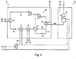
- Fig. 2 shows the parts compression refrigeration system 5 and evaporative cooling system 6 of the system according to the invention.
- the refrigerant circulates. Frequently used as a refrigerant ammonia or propylene.
- the refrigerant stream 22 is compressed in two stages in the series-connected compressor 23 and 24 and cooled in heat exchanger 25 by means of cooling water and condensed in part.
- the refrigerant flow is then split into the streams 26 and 27.
- the stream 27 is expanded in the valve 28, thereby cooled and used to cool the stream 26 in the heat exchanger 29 and then returned before compressor 24 back into the main stream.
- the refrigerant stream 26 is, after cooling in heat exchanger 29 in heat exchanger 30 by the, in the Rectisolstrom 4, Fig. 1 separated carbon dioxide stream 19 a cooled. From the air separation 2, Fig. 1 the nitrogen stream 9a produced there is brought in, relaxed and cooled in the turbine 20.
- the nitrogen stream is then used in heat exchanger 31 for cooling the refrigerant flow.
- the refrigerant flow in the valve 32 is expanded, thereby further cooled and then, in the heat exchanger 22 for cooling the Absorbent methanol 16 a, b used.
- cooling water 18 a is introduced into the evaporative cooler 33 of the partial layer 6.
- residual gas 10 from the air separation 2, Fig. 1 and the nitrogen stream 9 c introduced into the evaporative cooler 33. These gases are loaded with moisture, as stream 17, discharged from the system and disposed of.
- the cooled in the evaporative cooler 33 cooling water 18 b is passed into the compression refrigeration system 5, used there in the heat exchanger 25 for cooling and condensation of the refrigerant and then, as a current 18 c, discharged from the system.
- the invention provides a possibility in the production of sour gas-free synthesis gas to reduce the cost of electrical energy.
- the invention is therefore industrially applicable.
Landscapes
- Chemical & Material Sciences (AREA)
- Engineering & Computer Science (AREA)
- Organic Chemistry (AREA)
- Combustion & Propulsion (AREA)
- Chemical Kinetics & Catalysis (AREA)
- Inorganic Chemistry (AREA)
- General Chemical & Material Sciences (AREA)
- Oil, Petroleum & Natural Gas (AREA)
- Mechanical Engineering (AREA)
- Physics & Mathematics (AREA)
- Thermal Sciences (AREA)
- General Engineering & Computer Science (AREA)
- Analytical Chemistry (AREA)
- General Health & Medical Sciences (AREA)
- Health & Medical Sciences (AREA)
- Separation By Low-Temperature Treatments (AREA)
- Industrial Gases (AREA)
Abstract
Description
- Die Erfindung betrifft ein Verfahren zur Erzeugung eines hauptsächlich aus Kohlenmonoxid und Wasserstoff bestehenden und von Sauergasen befreiten Synthesegases, ausgehend von einem kohlenwasserstoffhaltigen Brennstoff, sowie Luft und Dampf, umfassend die folgenden Verfahrensschritte:
- Zerlegung von Luft durch Tieftemperatur-Rektifikation in einen Sauerstoff-, einen Restgas- und ein Stickstoffstrom, wobei der Restgas- und der Stickstoffstrom Umgebungstemperatur und der Stickstoffstrom einen erhöhten Druck hat
- Umwandlung eines kohlenwasserstoffhaltigen Brennstoffs bei erhöhter Temperatur und erhöhtem Druck mit dem Sauerstoffstrom und dem Dampf, nach einem dem Fachmann bekannten Verfahren, in ein Synthesegas
- Abtrennung der Sauergase aus dem Synthesegas durch Tieftemperatur-Absorption in einer Absorptionskolonne mit einem flüssigen Absorptionsmittel
- Kühlung des verwendeten Absorptionsmittels auf die für die Tieftemperatur-Absorption notwendige tiefe Temperatur mittels einer Kompressionskälteanlage, wobei die Kompressionskälteanlage einen Kältemittelkreislauf umfasst in dem das Kältemittel komprimiert und die dabei auf das Kältemittel übertragene Kompressionswärme durch anschließenden Wärmeaustausch mit Kühlwasser wieder dem Kältemittel entzogen wird,
- Kühlung des Kühlwassers vor dessen Wärmeaustausch mit dem Kältemittel durch Verdunstungskühlung.
- Die Erfindung umfasst ebenso eine Anlage zur Durchführung des Verfahrens.
- Die der Erfindung zugrunde liegenden Verfahren, kryogene Luftzerlegung, Erzeugung von Synthesegas aus einem kohlensfoffhaltigem Brennstoff und die kryogene Abtrennung von Sauergas aus dem (Roh-)Synthesegas gehören zum Stand der Technik.
- Kryogene Luftzerlegung, auch Tieftemperatur-Zerlegung genannt, ist seit den 1920ziger Jahre bekannt und grundsätzlich z.B. in Ullmann's Encyclopedia of Industrial Chemistry, 6th Edition, Vol. 10, S. 39, 40 beschrieben. Im Zusammenhang mit Synthesegasproduktion wird häufig von den bekannten Luftzerlegungsverfahren die Doppelsäulen-Rektifikation verwendet, da dabei, neben dem Sauerstoffstrom, auch ein Strom reinen Stickstoffs erzeugt wird, der häufig in der Synthesegasproduktion nachgeschalteten Anlagen verwendet werden kann. Eine Ausführungsart der Doppelsäulen-Rektifikation, die häufig für die Synthesegasproduktion verwendet wird, ist in dem Fachbuch Gasification, Second Edition, Christopher Higman, Maarten van der Burgt, Gulf Professional Publishing, Elsevier, Burlington, USA beschrieben.
- Bei dieser Ausführungsart wird der aus der Umgebung angesaugte Luftstrom verdichtet und einer Vorreinigung unterzogen, bei der in einem Adsorptionsschritt Feuchte und langkettige Kohlenwasserstoffmoleküle und dann, mittels Molekularsieb, Kohlendioxid und die übrigen Kohlenwasserstoffe abgetrennt werden. Der so behandelte Luftstrom wird dann in Wärmeaustausch mit den die Doppelsäulen-Rektifikation verlassenden Produktströme, Sauerstoff, Stickstoff und Restgas, gebracht.
- Der Wärmeaustausch wird so durchgeführt, dass die komprimierte Luft bis auf ihre Kondensationstemperatur abgekühlt und die Produktströme bis auf Umgebungstemperatur erwärmt werden. Dabei wird das Verfahren häufig so durchgeführt, dass der Stickstoffproduktstrom, nach dem Wärmeaustausch und der dabei erfolgten Erwärmung auf Raumtemperatur, einen erhöhten Druck von ca. 5 - 6 bar besitzt. Dieser Stickstoff kann als Utility für andere Anlagen oder, z.B. nach Entspannung und Abkühlung, zur Vorkühlung der Luft für die Luftzerlegungsanlage verwendet werden.
- Der in der Luftzerlegung produzierte Sauerstoff wird anschließend, zusammen mit einem Dampfstrom, zur Umwandlung, auch Vergasung genannt, eines kohlenwasserstoffhaltigen Brennstoffs zu hauptsächlich aus Wasserstoff und Kohlenmonoxid bestehendem Synthesegas verwendet. Als Brennstoff wird häufig Kohle, Koks oder Erdgas verwendet, aber auch flüssige Kohlenwasserstoffe oder Biomasse. Eine Vielzahl von Verfahren und Reaktortypen sind für die jeweilig vorliegenden Brennstoffe entwickelt worden. Einen Überblick über diese Vergasungsverfahren gibt z. B. auch das oben erwähnte Fachbuch Gasification.
- Grundsätzlich sind alle diese Vergasungsverfahren für die vorliegende Erfindung einsetzbar.
- Für die weitere Verwendung des Synthesegases, als Rohstoff für die Produktion von z.B. Methanol, Ammoniak oder Wasserstoff oder als Brenngas, müssen aus ihm Kohlendioxid und Schwefelwasserstoff, zusammenfassend oft als Sauergase bezeichnet, abgetrennt werden. Dies geschieht sehr wirksam mit einem Tieftemperaturabsorptionsverfahren, bei dem tief abgekühltes Methanol als Absorptionsmittel verwendet wird. Das Verfahren ist unter dem Namen Rectisol Prozess seit den 1950-ziger Jahren bekannt. Eine Beschreibung ist z.B. in Ullmann's Encyclopedia of Industrial Chemistry, 6th edition, Vol. 15, S. 399 ff gegeben. Die Sauergase werden dabei in einer Kolonne, im Gegenstrom, vom tiefkalten Methanol ausgewaschen. Beim sogenannten Standard-Rectisol-Prozess werden beide Sauergase, Kohlendioxid und Schwefelwasserstoff, in einer Kolonne ausgewaschen. Das zu waschende Synthesegas tritt am Boden in die Kolonne ein, im unteren Teil der Kolonne wird hauptsächlich Schwefelwasserstoff und dann, im oberen Teil, hauptsächlich Kohlendioxid ausgewaschen. Bei der Regenerierung des Methanols werden die Sauergase als Gasgemisch gewonnen und zur weiteren Behandlung abgeführt. Für den Fall, dass man Kohlendioxid und Schwefelwasserstoff getrennt gewinnen will, wurde das sogenannte selektive Rectisol-Verfahren entwickelt. Dabei durchströmt das zu reinigende Synthesegas zwei nacheinander angeordnete Wasch- bzw. Absorptionskolonnen. In der ersten wird Schwefelwasserstoff, in der zweiten Kohlendioxid abgetrennt. Die Gase werden so getrennt gehalten und können anschließend jeweils aus dem beladenen Methanol ausgetrieben werden. Für die vorliegende Erfindung können sowohl das Standard als auch das Selektive Rectisol-Verfahren zum Einsatz kommen. Die Einstellung der für das Verfahren erforderlichen tiefen Temperatur des Methanols erfolgt, indem ein beladener Methanolstrom, der durch die Absorption erwärmt wurde, der Absorptionskolonne entnommen, durch Wärmeaustausch mit einem Kühlmedium gekühlt und dann wieder in die Kolonne eingespeist wird. Als Kühlmedium wird häufig Ammoniak, das in einer Kompressionskühlanlage entsprechend heruntergekühlt wird. Die in der Kompressionskühlanlage auf das Kühlmedium übertragene Kompressionsenergie führt zu einer Erwärmung des Kühlmediums. Durch Wärmeaustausch mit Kühlwasser wird diese Wärme dem Kühlmedium wieder entzogen. Das Kühlwasser selbst wird, vor dem Wärmeaustausch mit dem Kühlmedium, durch Verdunstungskühlung gekühlt.
- Das Verfahren erfordert insbesondere in den Schritten Herstellung des Vergasungsmittels durch Luftzerlegung und Abtrennung des Sauergases einen hohen Aufwand an elektrischer Energie, z.B. für die Komprimierung der Luft für die Luftzerlegung und die Komprimierung des Kältemittels in der Kompressionskälteanlage zur Kühlung des Absorptionsmittels.
- Die Aufgabe der Erfindung ist es daher, eine Variante des Verfahrens zur Verfügung zu stellen, die einen niedrigeren Verbrauch an elektrischer Energie zu ihrem Betrieb aufweist.
- Die Aufgabe wird durch ein Verfahren gemäß den Merkmalen des Anspruchs 1 und durch eine Anlage gemäß den Merkmalen des Anspruchs 3 gelöst.
- Im ersten Schritt des erfindungsgemäßen Verfahrens, der Luftzerlegung, wird als Neben- bzw. Abfallprodukt, mit hohem apparativen und energetischen Aufwand hochgespannter Stickstoff und ein Restgasstrom erzeugt. Diese Ströme sind vollkommen trocken und die Erfindung nutzt deren dadurch gegebene, besonders gute Aufnahmefähigkeit für Feuchte, indem sie diese Ströme für die Verdunstungskühlung des für die Kompressionskälteanlage der Rectisol-Anlage benötigten Kühlwassers nutzt. Im Vergleich zur Verwendung von Umgebungsluft, die fast immer einen gewissen Feuchteanteil enthält, kann so eine tiefere Kühlwassertemperatur und damit wiederum eine tiefere Temperatur des Kältemittels erreicht werden. Durch die Kompression wird das Kältemittel im Kältemittelkreislauf erwärmt und anschließend, durch Wärmeaustausch mit Kühlwasser, wieder gekühlt. Der Vorteil der Erfindung liegt darin, dass die für die Kühlung des Absorptionsmittels der Rectisol-Anlage notwendige tiefe Temperatur des Kältemittels mit einem geringeren Druck bei der Kondensierung des Kältemittels erfolgen kann. Der Verbrauch an elektrischer Energie zur Kompression des Kältemittels wird durch die Erfindung gesenkt.
- Das Kühlwasser, das im Verdunstungskühler gekühlt wird, wird dem Verfahren bzw. der Anlage von außen, z.B. von einer Kühlwasserversorgungsanlage, die nicht zum Umfang der Erfindung gehört, zugeführt und, nach Gebrauch, wieder von der erfindungsgemäßen Anlage dorthin wieder zurückgeführt.
- Im Verdunstungskühler wird das Kühlwasser mit dem Restgas- und/oder dem entspannten Stickstoffstrom in Kontakt gebracht. Dabei können dem Fachmann bekannte Mittel, wie strukturierte Packungen oder Füllkörperschüttungen, zum Einsatz kommen.
- Eine bevorzugte Ausgestaltung der Erfindung ist dadurch gekennzeichnet, dass der durch Luftzerlegung erzeugte Stickstoffstrom, bevor er zur Verdunstungskühlung des Kühlwassers verwendet wird, über eine Turbine entspannt, dabei abgekühlt und anschließend zur Kühlung des Kältemittels im Kältemittelkreislauf der Kompressionskälteanlage verwendet wird. Auf diese Weise wird auch das in diesem Strom enthaltenen Druckpotential zur Unterstützung der Kompressionskälteanlage ausgenutzt und der Energieaufwand für die Kompression gesenkt.
- Weiterbildungen, Vorteile und Anwendungsmöglichkeiten der Erfindung ergeben sich auch aus der nachfolgenden Beschreibung von nicht beschränkenden Ausführungs- und Zahlenbeispielen und den Zeichnungen. Dabei bilden alle beschriebenen und/oder bildlich dargestellten Merkmale für sich oder in beliebiger Kombination die Erfindung, unabhängig von ihrer Zusammenfassung in den Ansprüchen oder deren Rückbeziehung.
- Es zeigen die Figuren:
-
Fig. 1 , Blockschema der erfindungsgemäßen Anlage -
Fig. 2 , Verfahrensschema eines Kompressionskältemittelkreislaufs mit der erfindungsgemäßen Verwendung von Stickstoff und Restgas zur Kühlung des Kühlwassers - Im Folgenden sollen die Figuren der Zeichnung erläutert werden:
- In
Fig. 1 umfasst die erfindungsgemäße Anlage 1 die Teilanlagen kryogene Luftzerlegung 2, Vergasung 3, Rectisolanlage 4, Kompressionskälteanlage 5 und den Verdunstungskühlanlage 6. Luft 7 wird aus der Umgebung angesaugt und in der Luftzerlegung 2 in einen Sauerstoff 8 -, einen Stickstoff 9 a- und einen Restgasstrom 10 zerlegt. Der Vergasungsanlage 3 wird kohlenstoffhaltiger Brennstoff 11 zugeführt und darin mit dem Sauerstoffstrom 8 und der Anlage zugeführtem Dampf 12 in Rohsynthesegas 13 und Asche 14 umgewandelt. Das erzeugte Rohsynthesegas 13 wird der Rectisolanlage 4 zugeführt, wo durch kryogene Absorption, mit Methanol als Absorptionsmittel, die Sauergase Schwefelwasserstoff 34 und Kohlendioxid 19 abgetrennt werden. Der abgetrennte Schwefelwasserstoff wird als Strom 34 und das gereinigte Synthesegas als Strom 15 zur weiteren Behandlung aus der Anlage 1 ausgeleitet. Das abgetrennte Kohlendioxid 19 a wird zur Kühlung im Kältemittelkreislauf der Kompressionskälteanlage 5 verwendet und anschließend als Strom 19 b aus der Anlage zur weiteren Verwendung oder Entsorgung ausgeleitet. Das in der Rectisolanlage 4 verwendete Absorptionsmittel Methanol wird bei seiner Verwendung erwärmt und muss daher kontinuierlich gekühlt werden. Ein Strom erwärmten Methanols 16 a wird in die Kompressionskälteanlage 5 geleitet, dort gekühlt, und als Strom 16 b zurück in die Rectisolanlage 4 geführt. Die Kühlleistung der Teilanlage 5 wird unterstützt, indem der in der Luftzerlegung 2 erzeugte und in der Turbine 20 entspannte und dabei abgekühlte Stickstoffstrom 9 b zur Kühlung des Kältemittels im Kältemittelkreislauf der Kompressionskälteanlage 5 herangezogen wird. Der in der Turbine 20 entspannte und abgekühlte Stickstoffstrom 9 b wird in die Kompressionskälteanlage 5 geleitet, dort erwärmt und als Strom 9 c zum Kühlturm 6 geleitet, um dort, zusammen mit dem Restgasstrom 10 aus der Luftzerlegung 2, den Kühlturm zu durchströmen und das Kühlwasser durch Verdunstung zu kühlen, Das im Kühlturm mit Feuchte beladene Stickstoff-Restgasgemisch 17 wird zur weiteren Behandlung außerhalb der Anlage 1 ausgeleitet. Von einer außerhalb der Anlage 1 liegenden, nicht dargestellten Anlage wir Kühlwasser 18 a dem Kühlturm 6 zugeführt, darin gekühlt und als Strom 18 b der Kompressionskälteanlage 5 zugeführt und von dort, als Strom 18 c aus der Anlage 1 ausgeführt. -
Fig. 2 zeigt die Teile Kompressionskälteanlage 5 und Verdunstungskühlanlage 6 der erfindungsgemäßen Anlage. Im Kompressionskältemittelkreislauf 21 zirkuliert das Kältemittel. Häufig wird als Kältemittel Ammoniak oder auch Propylen verwendet. - Der Kältemittelstrom 22 wird in zwei Stufen in den hintereinander geschalteten Verdichter 23 und 24 komprimiert und in Wärmeaustauscher 25 mittels Kühlwasser gekühlt und zum Teil kondensiert. Der Kältemittelstrom wird dann in die Ströme 26 und 27 aufgeteilt. Der Strom 27 wird in Ventil 28 entspannt, dabei abgekühlt und zur Kühlung des Stroms 26 in Wärmeaustauscher 29 verwendet und anschließend vor Verdichter 24 wieder in den Hauptstrom zurückgeführt. Der Kältemittelstrom 26 wird, nach der Kühlung in Wärmetauscher 29 in Wärmetauscher 30 durch den, in der Rectisolanlage 4,
Fig. 1 abgetrennten Kohlendioxidstrom 19 a gekühlt. Aus der Luftzerlegung 2,Fig. 1 wird der dort erzeugte Stickstoffstrom 9 a herangeführt, in der Turbine 20 entspannt und abgekühlt. Als Strom 9 b wird der Stickstoffstrom dann in Wärmeaustauscher 31 zur Kühlung des Kältemittelstroms verwendet. Anschließend wird der Kältemittelstrom in Ventil 32 entspannt, dabei weiter abgekühlt und dann, in Wärmeaustauscher 22 zur Kühlung des Absorptionsmittels Methanol 16 a, b verwendet. Von einer nicht dargestellten und nicht zur Anlage gehörenden Versorgungseinrichtung wird Kühlwasser 18 a in den Verdunstungskühler 33 der Teilenlage 6 eingeleitet. Ebenso wird Restgas 10 aus der Luftzerlegung 2,Fig. 1 und der Stickstoffstrom 9 c in den Verdunstungskühler 33 eingeleitet. Diese Gase werden mit Feuchtigkeit beladen, als Strom 17, aus der Anlage ausgeleitet und entsorgt. Das im Verdunstungskühler 33 gekühlte Kühlwasser 18 b wird in die Kompressionskälteanlage 5 geleitet, dort in Wärmeaustauscher 25 zur Kühlung und Kondensation des Kältemittels verwendet und dann, als Strom 18 c, aus der Anlage ausgeleitet. - Die Erfindung liefert eine Möglichkeit bei der Herstellung von sauergasbefreitem Synthesegas, den Aufwand an elektrischer Energie zu senken. Die Erfindung ist daher gewerblich anwendbar.
-
- 1
- erfindungsgemäßes Verfahren/Anlage
- 2
- Tieftemperatur-Luftzerlegung
- 3
- Vergasung
- 4
- Tieftemperatur-Absorption (Rectisol-Anlage)
- 5
- Kompressionskälteanlage
- 6
- Verdunstungskühlanlage
- 7
- Luft
- 8
- Sauerstoff
- 9
- Stickstoff
- 10
- Restgas
- 11
- Kohlenwasserstoffhaltiger Brennstoff
- 12
- Dampf
- 13
- Rohsynthesegas, Sauergase enthaltend
- 14
- Reststoff/Asche
- 15
- Synthesegas, frei von Sauergasen
- 16
- a, b Methanol
- 17
- Stickstoff-Restgas-Gemisch, beladen mit Feuchte
- 18
- a, b, c Kühlwasser
- 19
- a, b Kohlendioxid
- 20
- Turbine
- 21
- Kompressionskältemittelkreislauf
- 22
- Kältemittelstrom
- 23
- Verdichter
- 24
- Verdichter
- 25
- Wärmeaustauscher
- 26
- Kältemittelstrom
- 27
- Kältemittelstrom
- 28
- Ventil
- 29
- Wärmeaustauscher
- 30
- Wärmeaustauscher
- 31
- Wärmeaustauscher
- 32
- Ventil
- 33
- Verdunstungskühler
Claims (3)
- Verfahren zur Erzeugung eines hauptsächlich aus Kohlenmonoxid und Wasserstoff bestehenden und von Sauergasen befreiten Synthesegases, ausgehend von einem kohlenwasserstoffhaltigen Brennstoff, sowie Luft und Dampf, umfassend die folgenden Verfahrensschritte:a) Zerlegung von Luft durch Tieftemperatur-Rektifikation in einen Sauerstoff-, einen Restgas- und ein Stickstoffstrom, wobei der Restgas- und der Stickstoffstrom Umgebungstemperatur und der Stickstoffstrom einen erhöhten Druck hat,b) Umwandlung eines kohlenwasserstoffhaltigen Brennstoffs bei erhöhter Temperatur und erhöhtem Druck mit dem in Schritt a) erzeugten Sauerstoffstrom und dem Dampf, nach einem dem Fachmann bekannten Verfahren, in ein Synthesegas,c) Abtrennung der Sauergase aus dem in Schritt b) erzeugten Synthesegas durch Tieftemperatur-Absorption in einer Absorptionskolonne mit einem flüssigen Absorptionsmittel,d) Kühlung des in Schritt c) verwendeten Absorptionsmittels auf die für die Tieftemperatur-Absorption notwendige tiefe Temperatur mittels einer Kompressionskälteanlage, wobei die Kompressionskälteanlage einen Kältemittelkreislauf umfasst, in dem das Kältemittel komprimiert und dadurch erwärmt und durch anschließenden Wärmeaustausch mit Kühlwasser gekühlt und kondensiert wird,e) Kühlung des Kühlwassers vor dessen Wärmeaustausch mit dem Kältemittel in Schritt d) durch Verdunstungskühlung,dadurch gekennzeichnet, dass die Verdunstungskühlung in Schritt e) mit dem in Schritt a) erzeugten Restgas- und/oder, nach dessen Entspannung, mit dem in Schritt a) erzeugten Stickstoffstrom durchgeführt wird.
- Verfahren gemäß Anspruch 1, dadurch gekennzeichnet, dass der in Schritt a) von Anspruch 1 erzeugte Stickstoffstrom erst über eine Turbine entspannt und dabei abgekühlt, anschließend zur Kühlung durch Wärmeaustausch des Kältemittels im Kältemittelkreislauf der Kompressionskälteanlage und dann zur Verdunstungskühlung des Kühlwassers verwendet wird.
- Anlage zur Erzeugung von Synthesegas umfassend folgende Teilanlagen und Apparate:a) Anlage zur Zerlegung von Luft unter Verwendung einer nach dem Prinzip der kryogenen Rektifikation unter erhöhtem Druck arbeitenden Luftzerlegungsanlage, die geeignet ist einen Strom gasförmigen Sauerstoffs und einen Strom gasförmigen Stickstoffs erhöhten Drucks und Umgebungstemperatur, sowie einen Restgasstrom, zu erzeugen,b) Anlage zur Umwandlung eines kohlenstoffhaltigen Brennstoffs mit einem Vergasungsmittel zu einem hauptsächlich Wasserstoff und Kohlenmonoxid umfassenden Synthesegas, wobei die Teilanlagen a) und b) so verschaltet sind, dass der in Teilanlage a) erzeugte Sauerstoff dem in Teilanlage b) verwendeten Vergasungsmittel beigefügt werden kann,c) Anlage zur Abtrennung der Sauergase Kohlendioxid und Schwefelwasserstoff aus dem in Teilanlage b) erzeugten Rohsynthesegas durch Absorption bei tiefer Temperatur mit einem flüssigen Absorptionsmittel, wie z.B. Methanol,d) Kompressionskälteanlage, ein Kältemittel enthaltend, wie z.B. Ammoniak oder Propylene) Verdunstungskühler zum Kühlen von Kühlwasserf) Optional eine Entspannungsturbine
Priority Applications (7)
| Application Number | Priority Date | Filing Date | Title |
|---|---|---|---|
| EP16400057.2A EP3333124B1 (de) | 2016-12-09 | 2016-12-09 | Anlage und verfahren zur erzeugung von synthesegas |
| PCT/EP2017/025340 WO2018103891A1 (en) | 2016-12-09 | 2017-11-20 | Plant and method for generation of synthesis gas |
| US16/467,668 US11485634B2 (en) | 2016-12-09 | 2017-11-20 | Plant and method for generation of synthesis gas |
| RU2019119774A RU2754422C2 (ru) | 2016-12-09 | 2017-11-20 | Установка и способ получения синтез-газа |
| AU2017373374A AU2017373374B2 (en) | 2016-12-09 | 2017-11-20 | Plant and method for generation of synthesis gas |
| CN201721705021.9U CN207845153U (zh) | 2016-12-09 | 2017-12-08 | 用于产生合成气的设备 |
| CN201711295116.2A CN108217594B (zh) | 2016-12-09 | 2017-12-08 | 用于产生合成气的设备和方法 |
Applications Claiming Priority (1)
| Application Number | Priority Date | Filing Date | Title |
|---|---|---|---|
| EP16400057.2A EP3333124B1 (de) | 2016-12-09 | 2016-12-09 | Anlage und verfahren zur erzeugung von synthesegas |
Publications (2)
| Publication Number | Publication Date |
|---|---|
| EP3333124A1 true EP3333124A1 (de) | 2018-06-13 |
| EP3333124B1 EP3333124B1 (de) | 2019-06-26 |
Family
ID=57960213
Family Applications (1)
| Application Number | Title | Priority Date | Filing Date |
|---|---|---|---|
| EP16400057.2A Active EP3333124B1 (de) | 2016-12-09 | 2016-12-09 | Anlage und verfahren zur erzeugung von synthesegas |
Country Status (6)
| Country | Link |
|---|---|
| US (1) | US11485634B2 (de) |
| EP (1) | EP3333124B1 (de) |
| CN (2) | CN108217594B (de) |
| AU (1) | AU2017373374B2 (de) |
| RU (1) | RU2754422C2 (de) |
| WO (1) | WO2018103891A1 (de) |
Families Citing this family (1)
| Publication number | Priority date | Publication date | Assignee | Title |
|---|---|---|---|---|
| FR3124179B1 (fr) * | 2021-06-16 | 2025-11-07 | Technip France | Procédé de traitement d’un flux gazeux issu de la pyrolyse de plastique et/ou de la pyrolyse de biomasse, et installation visant à l’intégration dans un vapocraqueur |
Citations (6)
| Publication number | Priority date | Publication date | Assignee | Title |
|---|---|---|---|---|
| EP0556691A1 (de) * | 1992-02-20 | 1993-08-25 | RUHR OEL GmbH | Verfahren zur Vergasung kohlenstoffhaltiger Rückstände der Mineralölverarbeitung |
| WO2004089499A2 (en) * | 2003-04-03 | 2004-10-21 | Fluor Corporation | Configurations and methods of carbon capture |
| DE102005046790A1 (de) * | 2005-09-29 | 2007-04-05 | Linde Ag | Verfahren zur Reinigung eines Gasgemisches |
| US20100018216A1 (en) * | 2008-03-17 | 2010-01-28 | Fassbender Alexander G | Carbon capture compliant polygeneration |
| EP2292554A1 (de) * | 2009-09-02 | 2011-03-09 | Ammonia Casale S.A. | Herstellung von Ammoniak-Zusatz-Syngas mit kyrogener Reinigung |
| EP2498033A2 (de) * | 2011-03-11 | 2012-09-12 | General Electric Company | System und Verfahren zum Kühlen eines Lösungsmittels zur Gasbehandlung |
Family Cites Families (5)
| Publication number | Priority date | Publication date | Assignee | Title |
|---|---|---|---|---|
| US5345756A (en) * | 1993-10-20 | 1994-09-13 | Texaco Inc. | Partial oxidation process with production of power |
| EP1944268A1 (de) * | 2006-12-18 | 2008-07-16 | BP Alternative Energy Holdings Limited | Verfahren |
| US8617270B2 (en) * | 2008-12-03 | 2013-12-31 | Kellogg Brown & Root Llc | Systems and methods for improving ammonia synthesis efficiency |
| CN102985398B (zh) * | 2010-06-24 | 2015-04-15 | 赫多特普索化工设备公司 | 甲醇和氨的共同生产 |
| DE102015101415A1 (de) * | 2015-01-30 | 2016-08-04 | L'Air Liquide, Société Anonyme pour l'Etude et l'Exploitation des Procédés Georges Claude | Verfahren und Anlage zur Reinigung von Rohgasen mittels physikalischer Gaswäsche |
-
2016
- 2016-12-09 EP EP16400057.2A patent/EP3333124B1/de active Active
-
2017
- 2017-11-20 US US16/467,668 patent/US11485634B2/en active Active
- 2017-11-20 RU RU2019119774A patent/RU2754422C2/ru active
- 2017-11-20 WO PCT/EP2017/025340 patent/WO2018103891A1/en not_active Ceased
- 2017-11-20 AU AU2017373374A patent/AU2017373374B2/en not_active Ceased
- 2017-12-08 CN CN201711295116.2A patent/CN108217594B/zh not_active Expired - Fee Related
- 2017-12-08 CN CN201721705021.9U patent/CN207845153U/zh not_active Expired - Fee Related
Patent Citations (6)
| Publication number | Priority date | Publication date | Assignee | Title |
|---|---|---|---|---|
| EP0556691A1 (de) * | 1992-02-20 | 1993-08-25 | RUHR OEL GmbH | Verfahren zur Vergasung kohlenstoffhaltiger Rückstände der Mineralölverarbeitung |
| WO2004089499A2 (en) * | 2003-04-03 | 2004-10-21 | Fluor Corporation | Configurations and methods of carbon capture |
| DE102005046790A1 (de) * | 2005-09-29 | 2007-04-05 | Linde Ag | Verfahren zur Reinigung eines Gasgemisches |
| US20100018216A1 (en) * | 2008-03-17 | 2010-01-28 | Fassbender Alexander G | Carbon capture compliant polygeneration |
| EP2292554A1 (de) * | 2009-09-02 | 2011-03-09 | Ammonia Casale S.A. | Herstellung von Ammoniak-Zusatz-Syngas mit kyrogener Reinigung |
| EP2498033A2 (de) * | 2011-03-11 | 2012-09-12 | General Electric Company | System und Verfahren zum Kühlen eines Lösungsmittels zur Gasbehandlung |
Non-Patent Citations (3)
| Title |
|---|
| "Ullmann's Encyclopedia of Industrial Chemistry", vol. 10, pages: 39,40 |
| "Ullmann's Encyclopedia of Industrial Chemistry", vol. 15, pages: 399 FF |
| CHRISTOPHER HIGMAN; MAARTEN VAN DER BURGT: "Fachbuch Gasification", GULF PROFESSIONAL PUBLISHING, ELSEVIER, BURLINGTON, USA |
Also Published As
| Publication number | Publication date |
|---|---|
| RU2019119774A (ru) | 2020-12-25 |
| CN207845153U (zh) | 2018-09-11 |
| US20200087143A1 (en) | 2020-03-19 |
| CN108217594A (zh) | 2018-06-29 |
| US11485634B2 (en) | 2022-11-01 |
| AU2017373374B2 (en) | 2021-09-16 |
| AU2017373374A1 (en) | 2019-07-04 |
| WO2018103891A1 (en) | 2018-06-14 |
| EP3333124B1 (de) | 2019-06-26 |
| CN108217594B (zh) | 2022-12-30 |
| RU2019119774A3 (de) | 2021-02-24 |
| RU2754422C2 (ru) | 2021-09-02 |
Similar Documents
| Publication | Publication Date | Title |
|---|---|---|
| DE1544080C3 (de) | ||
| EP3390354B1 (de) | Verfahren zur bereitstellung von kohlendioxid für die synthese von harnstoff | |
| DE112011105958B4 (de) | Verfahren und Anlage zur Abtrennung von Kohlendioxid aus methan- und schwefelwasserstoffhaltigen Biogasen | |
| DE1494808B2 (de) | Verfahren zum reinigen von brenn- oder synthesegasen | |
| EP3666364B1 (de) | Verfahren und vorrichtung zur regenerierung eines beladenen waschmittels aus einer gaswäsche | |
| DE102007005494A1 (de) | Verfahren und Anlage zur Gewinnung von flüssigem Methan aus methan- und kohlendioxidhaltigen Rohgasen, insbesondere Biogas | |
| DE102005051952B3 (de) | Verfahren zur Herstellung von Methan und flüssigem Kohlendioxid aus Raffinerie- und/oder Biogas | |
| DE102010022501A1 (de) | Verfahren und Vorrichtung zur Wäsche von Synthesegas | |
| EP3583996A1 (de) | Verfahren und anlage zur herstellung von syngasprodukte | |
| EP1961697A1 (de) | Erzeugung von Produkten aus Raffinerieabgasen | |
| EP3333124B1 (de) | Anlage und verfahren zur erzeugung von synthesegas | |
| WO2009124666A2 (de) | Verfahren und vorrichtung zur erzeugung von wasserstoff und/oder kohlenmonoxid aus koks | |
| EP3333123B1 (de) | Verfahren und anlage zur erzeugung von synthesegas | |
| EP1519781B1 (de) | Anlageneinheit zur desorption von kohlendioxid aus methanol | |
| DE102016013753A1 (de) | Verfahren und Vorrichtung zur Synthesegaszerlegung mittels Sauergaswäsche und kryogenem Trennprozess | |
| DE1567690A1 (de) | Verfahren zur Herstellung von Wasserstoff insbesondere fuer die Ammoniak-Synthese | |
| DE1296133B (de) | Verfahren zur Herstellung von Methanol-Synthesegas | |
| DE1567690C3 (de) | Verfahren zur Herstellung von Wasserstoff aus CO- und H2 -reichen, CO2 und Schwefelverbindungen enthaltenden Rohgasen | |
| DE102022116801A1 (de) | Verfahren zum Aufbereiten von Biogas und/oder Erdgas zum Herstellen von verflüssigtem Methan und Aufbereitungsanlage | |
| DE1494808C3 (de) | ||
| DE102014015160A1 (de) | Verfahren und Vorrichtung zur Gewinnung von Kohlenmonoxid und Wasserstoff aus Synthesegas | |
| DE1494802A1 (de) | Verfahren zur Abtrennung von Methan und Aethan aus kohlensaeurereichen Druckgasen | |
| DE2124056A1 (en) | Regeneration of solvents - used to wash acid gases from natural gas, by stripping with flue gases | |
| DE2007441A1 (en) | Hydrogen-nitrogen mixture prodn | |
| DE2025763B (de) | Verfahren zum Gewinnen von Wasserstoff und Kohlenmonoxid |
Legal Events
| Date | Code | Title | Description |
|---|---|---|---|
| PUAI | Public reference made under article 153(3) epc to a published international application that has entered the european phase |
Free format text: ORIGINAL CODE: 0009012 |
|
| STAA | Information on the status of an ep patent application or granted ep patent |
Free format text: STATUS: THE APPLICATION HAS BEEN PUBLISHED |
|
| AK | Designated contracting states |
Kind code of ref document: A1 Designated state(s): AL AT BE BG CH CY CZ DE DK EE ES FI FR GB GR HR HU IE IS IT LI LT LU LV MC MK MT NL NO PL PT RO RS SE SI SK SM TR |
|
| AX | Request for extension of the european patent |
Extension state: BA ME |
|
| STAA | Information on the status of an ep patent application or granted ep patent |
Free format text: STATUS: REQUEST FOR EXAMINATION WAS MADE |
|
| 17P | Request for examination filed |
Effective date: 20180907 |
|
| RBV | Designated contracting states (corrected) |
Designated state(s): AL AT BE BG CH CY CZ DE DK EE ES FI FR GB GR HR HU IE IS IT LI LT LU LV MC MK MT NL NO PL PT RO RS SE SI SK SM TR |
|
| GRAP | Despatch of communication of intention to grant a patent |
Free format text: ORIGINAL CODE: EPIDOSNIGR1 |
|
| STAA | Information on the status of an ep patent application or granted ep patent |
Free format text: STATUS: GRANT OF PATENT IS INTENDED |
|
| INTG | Intention to grant announced |
Effective date: 20190213 |
|
| GRAS | Grant fee paid |
Free format text: ORIGINAL CODE: EPIDOSNIGR3 |
|
| GRAA | (expected) grant |
Free format text: ORIGINAL CODE: 0009210 |
|
| STAA | Information on the status of an ep patent application or granted ep patent |
Free format text: STATUS: THE PATENT HAS BEEN GRANTED |
|
| AK | Designated contracting states |
Kind code of ref document: B1 Designated state(s): AL AT BE BG CH CY CZ DE DK EE ES FI FR GB GR HR HU IE IS IT LI LT LU LV MC MK MT NL NO PL PT RO RS SE SI SK SM TR |
|
| REG | Reference to a national code |
Ref country code: GB Ref legal event code: FG4D Free format text: NOT ENGLISH |
|
| REG | Reference to a national code |
Ref country code: CH Ref legal event code: EP |
|
| REG | Reference to a national code |
Ref country code: DE Ref legal event code: R096 Ref document number: 502016005233 Country of ref document: DE |
|
| REG | Reference to a national code |
Ref country code: AT Ref legal event code: REF Ref document number: 1148072 Country of ref document: AT Kind code of ref document: T Effective date: 20190715 |
|
| REG | Reference to a national code |
Ref country code: IE Ref legal event code: FG4D Free format text: LANGUAGE OF EP DOCUMENT: GERMAN |
|
| REG | Reference to a national code |
Ref country code: NL Ref legal event code: FP |
|
| PG25 | Lapsed in a contracting state [announced via postgrant information from national office to epo] |
Ref country code: LT Free format text: LAPSE BECAUSE OF FAILURE TO SUBMIT A TRANSLATION OF THE DESCRIPTION OR TO PAY THE FEE WITHIN THE PRESCRIBED TIME-LIMIT Effective date: 20190626 Ref country code: FI Free format text: LAPSE BECAUSE OF FAILURE TO SUBMIT A TRANSLATION OF THE DESCRIPTION OR TO PAY THE FEE WITHIN THE PRESCRIBED TIME-LIMIT Effective date: 20190626 Ref country code: AL Free format text: LAPSE BECAUSE OF FAILURE TO SUBMIT A TRANSLATION OF THE DESCRIPTION OR TO PAY THE FEE WITHIN THE PRESCRIBED TIME-LIMIT Effective date: 20190626 Ref country code: SE Free format text: LAPSE BECAUSE OF FAILURE TO SUBMIT A TRANSLATION OF THE DESCRIPTION OR TO PAY THE FEE WITHIN THE PRESCRIBED TIME-LIMIT Effective date: 20190626 Ref country code: HR Free format text: LAPSE BECAUSE OF FAILURE TO SUBMIT A TRANSLATION OF THE DESCRIPTION OR TO PAY THE FEE WITHIN THE PRESCRIBED TIME-LIMIT Effective date: 20190626 |
|
| REG | Reference to a national code |
Ref country code: NO Ref legal event code: T2 Effective date: 20190626 |
|
| REG | Reference to a national code |
Ref country code: LT Ref legal event code: MG4D |
|
| PG25 | Lapsed in a contracting state [announced via postgrant information from national office to epo] |
Ref country code: GR Free format text: LAPSE BECAUSE OF FAILURE TO SUBMIT A TRANSLATION OF THE DESCRIPTION OR TO PAY THE FEE WITHIN THE PRESCRIBED TIME-LIMIT Effective date: 20190927 Ref country code: LV Free format text: LAPSE BECAUSE OF FAILURE TO SUBMIT A TRANSLATION OF THE DESCRIPTION OR TO PAY THE FEE WITHIN THE PRESCRIBED TIME-LIMIT Effective date: 20190626 Ref country code: RS Free format text: LAPSE BECAUSE OF FAILURE TO SUBMIT A TRANSLATION OF THE DESCRIPTION OR TO PAY THE FEE WITHIN THE PRESCRIBED TIME-LIMIT Effective date: 20190626 Ref country code: BG Free format text: LAPSE BECAUSE OF FAILURE TO SUBMIT A TRANSLATION OF THE DESCRIPTION OR TO PAY THE FEE WITHIN THE PRESCRIBED TIME-LIMIT Effective date: 20190926 |
|
| PG25 | Lapsed in a contracting state [announced via postgrant information from national office to epo] |
Ref country code: EE Free format text: LAPSE BECAUSE OF FAILURE TO SUBMIT A TRANSLATION OF THE DESCRIPTION OR TO PAY THE FEE WITHIN THE PRESCRIBED TIME-LIMIT Effective date: 20190626 Ref country code: RO Free format text: LAPSE BECAUSE OF FAILURE TO SUBMIT A TRANSLATION OF THE DESCRIPTION OR TO PAY THE FEE WITHIN THE PRESCRIBED TIME-LIMIT Effective date: 20190626 Ref country code: CZ Free format text: LAPSE BECAUSE OF FAILURE TO SUBMIT A TRANSLATION OF THE DESCRIPTION OR TO PAY THE FEE WITHIN THE PRESCRIBED TIME-LIMIT Effective date: 20190626 Ref country code: PT Free format text: LAPSE BECAUSE OF FAILURE TO SUBMIT A TRANSLATION OF THE DESCRIPTION OR TO PAY THE FEE WITHIN THE PRESCRIBED TIME-LIMIT Effective date: 20191028 Ref country code: SK Free format text: LAPSE BECAUSE OF FAILURE TO SUBMIT A TRANSLATION OF THE DESCRIPTION OR TO PAY THE FEE WITHIN THE PRESCRIBED TIME-LIMIT Effective date: 20190626 |
|
| PG25 | Lapsed in a contracting state [announced via postgrant information from national office to epo] |
Ref country code: SM Free format text: LAPSE BECAUSE OF FAILURE TO SUBMIT A TRANSLATION OF THE DESCRIPTION OR TO PAY THE FEE WITHIN THE PRESCRIBED TIME-LIMIT Effective date: 20190626 Ref country code: IT Free format text: LAPSE BECAUSE OF FAILURE TO SUBMIT A TRANSLATION OF THE DESCRIPTION OR TO PAY THE FEE WITHIN THE PRESCRIBED TIME-LIMIT Effective date: 20190626 Ref country code: IS Free format text: LAPSE BECAUSE OF FAILURE TO SUBMIT A TRANSLATION OF THE DESCRIPTION OR TO PAY THE FEE WITHIN THE PRESCRIBED TIME-LIMIT Effective date: 20191026 Ref country code: ES Free format text: LAPSE BECAUSE OF FAILURE TO SUBMIT A TRANSLATION OF THE DESCRIPTION OR TO PAY THE FEE WITHIN THE PRESCRIBED TIME-LIMIT Effective date: 20190626 |
|
| PG25 | Lapsed in a contracting state [announced via postgrant information from national office to epo] |
Ref country code: TR Free format text: LAPSE BECAUSE OF FAILURE TO SUBMIT A TRANSLATION OF THE DESCRIPTION OR TO PAY THE FEE WITHIN THE PRESCRIBED TIME-LIMIT Effective date: 20190626 |
|
| PG25 | Lapsed in a contracting state [announced via postgrant information from national office to epo] |
Ref country code: DK Free format text: LAPSE BECAUSE OF FAILURE TO SUBMIT A TRANSLATION OF THE DESCRIPTION OR TO PAY THE FEE WITHIN THE PRESCRIBED TIME-LIMIT Effective date: 20190626 Ref country code: PL Free format text: LAPSE BECAUSE OF FAILURE TO SUBMIT A TRANSLATION OF THE DESCRIPTION OR TO PAY THE FEE WITHIN THE PRESCRIBED TIME-LIMIT Effective date: 20190626 |
|
| PG25 | Lapsed in a contracting state [announced via postgrant information from national office to epo] |
Ref country code: IS Free format text: LAPSE BECAUSE OF FAILURE TO SUBMIT A TRANSLATION OF THE DESCRIPTION OR TO PAY THE FEE WITHIN THE PRESCRIBED TIME-LIMIT Effective date: 20200224 |
|
| REG | Reference to a national code |
Ref country code: DE Ref legal event code: R097 Ref document number: 502016005233 Country of ref document: DE |
|
| PLBE | No opposition filed within time limit |
Free format text: ORIGINAL CODE: 0009261 |
|
| STAA | Information on the status of an ep patent application or granted ep patent |
Free format text: STATUS: NO OPPOSITION FILED WITHIN TIME LIMIT |
|
| PG2D | Information on lapse in contracting state deleted |
Ref country code: IS |
|
| REG | Reference to a national code |
Ref country code: CH Ref legal event code: PL |
|
| 26N | No opposition filed |
Effective date: 20200603 |
|
| PG25 | Lapsed in a contracting state [announced via postgrant information from national office to epo] |
Ref country code: SI Free format text: LAPSE BECAUSE OF FAILURE TO SUBMIT A TRANSLATION OF THE DESCRIPTION OR TO PAY THE FEE WITHIN THE PRESCRIBED TIME-LIMIT Effective date: 20190626 Ref country code: MC Free format text: LAPSE BECAUSE OF FAILURE TO SUBMIT A TRANSLATION OF THE DESCRIPTION OR TO PAY THE FEE WITHIN THE PRESCRIBED TIME-LIMIT Effective date: 20190626 |
|
| PG25 | Lapsed in a contracting state [announced via postgrant information from national office to epo] |
Ref country code: LU Free format text: LAPSE BECAUSE OF NON-PAYMENT OF DUE FEES Effective date: 20191209 Ref country code: IE Free format text: LAPSE BECAUSE OF NON-PAYMENT OF DUE FEES Effective date: 20191209 |
|
| PG25 | Lapsed in a contracting state [announced via postgrant information from national office to epo] |
Ref country code: CH Free format text: LAPSE BECAUSE OF NON-PAYMENT OF DUE FEES Effective date: 20191231 Ref country code: LI Free format text: LAPSE BECAUSE OF NON-PAYMENT OF DUE FEES Effective date: 20191231 |
|
| PG25 | Lapsed in a contracting state [announced via postgrant information from national office to epo] |
Ref country code: CY Free format text: LAPSE BECAUSE OF FAILURE TO SUBMIT A TRANSLATION OF THE DESCRIPTION OR TO PAY THE FEE WITHIN THE PRESCRIBED TIME-LIMIT Effective date: 20190626 |
|
| PG25 | Lapsed in a contracting state [announced via postgrant information from national office to epo] |
Ref country code: MT Free format text: LAPSE BECAUSE OF FAILURE TO SUBMIT A TRANSLATION OF THE DESCRIPTION OR TO PAY THE FEE WITHIN THE PRESCRIBED TIME-LIMIT Effective date: 20190626 Ref country code: HU Free format text: LAPSE BECAUSE OF FAILURE TO SUBMIT A TRANSLATION OF THE DESCRIPTION OR TO PAY THE FEE WITHIN THE PRESCRIBED TIME-LIMIT; INVALID AB INITIO Effective date: 20161209 |
|
| PG25 | Lapsed in a contracting state [announced via postgrant information from national office to epo] |
Ref country code: MK Free format text: LAPSE BECAUSE OF FAILURE TO SUBMIT A TRANSLATION OF THE DESCRIPTION OR TO PAY THE FEE WITHIN THE PRESCRIBED TIME-LIMIT Effective date: 20190626 |
|
| REG | Reference to a national code |
Ref country code: AT Ref legal event code: MM01 Ref document number: 1148072 Country of ref document: AT Kind code of ref document: T Effective date: 20211209 |
|
| PG25 | Lapsed in a contracting state [announced via postgrant information from national office to epo] |
Ref country code: AT Free format text: LAPSE BECAUSE OF NON-PAYMENT OF DUE FEES Effective date: 20211209 |
|
| PGFP | Annual fee paid to national office [announced via postgrant information from national office to epo] |
Ref country code: DE Payment date: 20241210 Year of fee payment: 9 |
|
| PGFP | Annual fee paid to national office [announced via postgrant information from national office to epo] |
Ref country code: NO Payment date: 20241227 Year of fee payment: 9 |
|
| PGFP | Annual fee paid to national office [announced via postgrant information from national office to epo] |
Ref country code: NL Payment date: 20241219 Year of fee payment: 9 Ref country code: BE Payment date: 20241219 Year of fee payment: 9 |
|
| PGFP | Annual fee paid to national office [announced via postgrant information from national office to epo] |
Ref country code: GB Payment date: 20241226 Year of fee payment: 9 |
|
| PGFP | Annual fee paid to national office [announced via postgrant information from national office to epo] |
Ref country code: FR Payment date: 20241224 Year of fee payment: 9 |