EP3333010B1 - Fahrzeugrücksitzrahmen und fahrzeug - Google Patents
Fahrzeugrücksitzrahmen und fahrzeug Download PDFInfo
- Publication number
- EP3333010B1 EP3333010B1 EP17203213.8A EP17203213A EP3333010B1 EP 3333010 B1 EP3333010 B1 EP 3333010B1 EP 17203213 A EP17203213 A EP 17203213A EP 3333010 B1 EP3333010 B1 EP 3333010B1
- Authority
- EP
- European Patent Office
- Prior art keywords
- frame
- seat
- vehicle
- seat cushion
- seat back
- Prior art date
- Legal status (The legal status is an assumption and is not a legal conclusion. Google has not performed a legal analysis and makes no representation as to the accuracy of the status listed.)
- Active
Links
Images


Classifications
-
- B—PERFORMING OPERATIONS; TRANSPORTING
- B60—VEHICLES IN GENERAL
- B60N—SEATS SPECIALLY ADAPTED FOR VEHICLES; VEHICLE PASSENGER ACCOMMODATION NOT OTHERWISE PROVIDED FOR
- B60N2/00—Seats specially adapted for vehicles; Arrangement or mounting of seats in vehicles
- B60N2/24—Seats specially adapted for vehicles; Arrangement or mounting of seats in vehicles for particular purposes or particular vehicles
- B60N2/30—Non-dismountable or dismountable seats storable in a non-use position, e.g. foldable spare seats
- B60N2/3002—Non-dismountable or dismountable seats storable in a non-use position, e.g. foldable spare seats back-rest movements
- B60N2/3004—Non-dismountable or dismountable seats storable in a non-use position, e.g. foldable spare seats back-rest movements by rotation only
- B60N2/3009—Non-dismountable or dismountable seats storable in a non-use position, e.g. foldable spare seats back-rest movements by rotation only about transversal axis
- B60N2/3011—Non-dismountable or dismountable seats storable in a non-use position, e.g. foldable spare seats back-rest movements by rotation only about transversal axis the back-rest being hinged on the cushion, e.g. "portefeuille movement"
-
- B—PERFORMING OPERATIONS; TRANSPORTING
- B60—VEHICLES IN GENERAL
- B60N—SEATS SPECIALLY ADAPTED FOR VEHICLES; VEHICLE PASSENGER ACCOMMODATION NOT OTHERWISE PROVIDED FOR
- B60N2/00—Seats specially adapted for vehicles; Arrangement or mounting of seats in vehicles
- B60N2/68—Seat frames
-
- B—PERFORMING OPERATIONS; TRANSPORTING
- B60—VEHICLES IN GENERAL
- B60N—SEATS SPECIALLY ADAPTED FOR VEHICLES; VEHICLE PASSENGER ACCOMMODATION NOT OTHERWISE PROVIDED FOR
- B60N2/00—Seats specially adapted for vehicles; Arrangement or mounting of seats in vehicles
- B60N2/02—Seats specially adapted for vehicles; Arrangement or mounting of seats in vehicles the seat or part thereof being movable, e.g. adjustable
- B60N2/22—Seats specially adapted for vehicles; Arrangement or mounting of seats in vehicles the seat or part thereof being movable, e.g. adjustable the back-rest being adjustable
-
- B—PERFORMING OPERATIONS; TRANSPORTING
- B60—VEHICLES IN GENERAL
- B60N—SEATS SPECIALLY ADAPTED FOR VEHICLES; VEHICLE PASSENGER ACCOMMODATION NOT OTHERWISE PROVIDED FOR
- B60N2/00—Seats specially adapted for vehicles; Arrangement or mounting of seats in vehicles
- B60N2/24—Seats specially adapted for vehicles; Arrangement or mounting of seats in vehicles for particular purposes or particular vehicles
- B60N2/30—Non-dismountable or dismountable seats storable in a non-use position, e.g. foldable spare seats
- B60N2/3002—Non-dismountable or dismountable seats storable in a non-use position, e.g. foldable spare seats back-rest movements
- B60N2/3004—Non-dismountable or dismountable seats storable in a non-use position, e.g. foldable spare seats back-rest movements by rotation only
- B60N2/3009—Non-dismountable or dismountable seats storable in a non-use position, e.g. foldable spare seats back-rest movements by rotation only about transversal axis
- B60N2/3013—Non-dismountable or dismountable seats storable in a non-use position, e.g. foldable spare seats back-rest movements by rotation only about transversal axis the back-rest being hinged on the vehicle frame
-
- B—PERFORMING OPERATIONS; TRANSPORTING
- B60—VEHICLES IN GENERAL
- B60N—SEATS SPECIALLY ADAPTED FOR VEHICLES; VEHICLE PASSENGER ACCOMMODATION NOT OTHERWISE PROVIDED FOR
- B60N2/00—Seats specially adapted for vehicles; Arrangement or mounting of seats in vehicles
- B60N2/24—Seats specially adapted for vehicles; Arrangement or mounting of seats in vehicles for particular purposes or particular vehicles
- B60N2/30—Non-dismountable or dismountable seats storable in a non-use position, e.g. foldable spare seats
- B60N2/3038—Cushion movements
- B60N2/304—Cushion movements by rotation only
- B60N2/3045—Cushion movements by rotation only about transversal axis
- B60N2/305—Cushion movements by rotation only about transversal axis the cushion being hinged on the vehicle frame
-
- B—PERFORMING OPERATIONS; TRANSPORTING
- B60—VEHICLES IN GENERAL
- B60N—SEATS SPECIALLY ADAPTED FOR VEHICLES; VEHICLE PASSENGER ACCOMMODATION NOT OTHERWISE PROVIDED FOR
- B60N2/00—Seats specially adapted for vehicles; Arrangement or mounting of seats in vehicles
- B60N2/24—Seats specially adapted for vehicles; Arrangement or mounting of seats in vehicles for particular purposes or particular vehicles
- B60N2/42—Seats specially adapted for vehicles; Arrangement or mounting of seats in vehicles for particular purposes or particular vehicles the seat constructed to protect the occupant from the effect of abnormal g-forces, e.g. crash or safety seats
- B60N2/4207—Seats specially adapted for vehicles; Arrangement or mounting of seats in vehicles for particular purposes or particular vehicles the seat constructed to protect the occupant from the effect of abnormal g-forces, e.g. crash or safety seats characterised by the direction of the g-forces
- B60N2/4214—Seats specially adapted for vehicles; Arrangement or mounting of seats in vehicles for particular purposes or particular vehicles the seat constructed to protect the occupant from the effect of abnormal g-forces, e.g. crash or safety seats characterised by the direction of the g-forces longitudinal
- B60N2/4228—Seats specially adapted for vehicles; Arrangement or mounting of seats in vehicles for particular purposes or particular vehicles the seat constructed to protect the occupant from the effect of abnormal g-forces, e.g. crash or safety seats characterised by the direction of the g-forces longitudinal due to impact coming from the rear
-
- B—PERFORMING OPERATIONS; TRANSPORTING
- B60—VEHICLES IN GENERAL
- B60N—SEATS SPECIALLY ADAPTED FOR VEHICLES; VEHICLE PASSENGER ACCOMMODATION NOT OTHERWISE PROVIDED FOR
- B60N2/00—Seats specially adapted for vehicles; Arrangement or mounting of seats in vehicles
- B60N2/24—Seats specially adapted for vehicles; Arrangement or mounting of seats in vehicles for particular purposes or particular vehicles
- B60N2/42—Seats specially adapted for vehicles; Arrangement or mounting of seats in vehicles for particular purposes or particular vehicles the seat constructed to protect the occupant from the effect of abnormal g-forces, e.g. crash or safety seats
- B60N2/427—Seats or parts thereof displaced during a crash
- B60N2/42709—Seats or parts thereof displaced during a crash involving residual deformation or fracture of the structure
Definitions
- the present disclosure relates to a vehicle rear seat frame and a vehicle including the rear seat frame.
- Patent Document 1 JP 2003 212017 A discloses a structure for housing a rear seat of a vehicle.
- a recessed section is formed at the rear position of the rear seat on a rear floor, and the frame of a seat cushion (seat cushion frame) of the rear seat is supported by a shaft disposed in the rear section of the seat cushion frame so as to be rotatable toward the vehicle rear side, so that the frame of a seat back (seat back frame) of the rear seat can be folded toward the seat cushion via a hinge portion.
- the rear seat can be housed in the recessed section by folding the seat back and rotating the seat cushion.
- Patent Document 2 ( US 2009/179477 A1 ) describes a vehicle seat comprising a seat frame having a cushion frame, the cushion frame with a first and second side frame, a bead extending from an outer side of the at least one of the first and second side frame, the bead including a first and second inclined surface connected at a ridge portion, and a notch portion defined in a lower portion of the at least one of the first and second side frame, wherein the notch portion is positioned proximate the bead.
- high-voltage parts such as driving batteries and inverters may be situated inside the recessed section on the rear floor.
- the housed rear seat is positioned behind the high-voltage parts.
- an object of at least one embodiment of the present invention is to provide a vehicle rear seat frame wherein impact caused by the housed seat toward the vehicle front side can be mitigated in a rear-end collision.
- a vehicle rear seat frame for a rear seat disposed in a rear section of a vehicle includes a seat cushion frame and a seat back frame being foldable about an axis along a lateral direction of the vehicle so as to be overlapped with each other.
- the seat cushion frame includes a seat cushion side frame at each lateral end of the seat cushion frame.
- the seat cushion side frame extends in a longitudinal direction of the vehicle when folded.
- the seat back frame includes a seat back side frame at each lateral end of the seat back frame.
- the seat back side frame extends in the longitudinal direction when folded.
- the seat cushion side frame includes a first weak portion having less longitudinal strength than other portions thereof.
- the seat back side frame includes a second weak portion having less longitudinal strength than other portions.
- FIG. 1 is a schematic perspective view for describing the positional relationship on a rear floor between a vehicle rear seat frame according to the present example and high-voltage parts
- FIG. 2 is a side view of the same.
- FIGs. 1 and 2 both show the vehicle rear seat frame according to the present example in a housed state (i.e. folded and rotated state).
- the vehicle rear seat frame is used as, for instance, an interior structure of a rear seat 10 disposed in the rear section of a vehicle V.
- the rear seat 10 is a foldable seat consisting of a rotatable seat cushion and a rotatable seat back.
- the rear seat 10 includes a vehicle rear seat frame 10F that includes a seat cushion frame 11 and a seat back frame 12, as shown in FIGs. 1 and 2 .
- the seat cushion frame 11 is supported by a shaft 21 that extends in the lateral direction (transverse or vehicle width direction) in the rear section of the seat cushion frame 11, so as to be rotatable about the shaft 21 and toward the vehicle rear side.
- the seat back frame 12 is also supported by the shaft 21 and is foldable toward the seat cushion frame 11, i.e., the seat back frame 12 is also rotatable about the shaft 21 so that it can be rotated forward and folded on top of the seat cushion frame 11.
- the seat cushion frame 11 and the seat back frame 12 can be housed by rotating the seat cushion frame 11 and the seat back frame 12 together toward the vehicle rear side (clockwise in FIG. 2 ) while the seat back frame 12 is folded toward the seat cushion frame 11.
- the seat cushion frame 11 and the seat back frame 12 are rotated until they become substantially horizontal so that they are overlapped with each other with the seat cushion frame 11 lying above the seat back frame 12.
- FIG. 2 the normal position of the rear seat 10 is shown in dashed lines, and rotation of the rear seat 10 toward the vehicle rear side is indicated by a chain-line arrow.
- the vehicle is provided with high-voltage parts 22 such as a driving battery or an inverter.
- the seat cushion frame 11 and the seat back frame 12 are positioned above the high-voltage parts 22 while the seat is in use. Furthermore, while the seat is housed as described above, the seat cushion frame 11 and the seat back frame 12 are positioned at the vehicle rear side of the high-voltage parts 22 and at the vehicle front side of a rear end 23. In the vehicle height direction, the seat cushion frame 11, the seat back frame 12, the high-voltage parts 22, and the rear end 23 are partially or entirely overlapped with each other (positioned at the same height).
- seat cushion side frames 11a, 11b that extend in the longitudinal direction (front-rear direction) of the vehicle V (in a state where the seat cushion frame 11 and the seat back frame 12 are housed) have respective curved portions A1 to A3, B1 to B3, as shown in the exploded perspective view of FIG. 3 .
- the curved portion A1 (first curved portion) is formed so as to project (or curve) outward in the vehicle width direction, in the vicinity of a through hole 11d of the shaft 21, that is, at a first end (proximal end) of the seat cushion side frame 11a, toward a second end (distal end) of the seat cushion side frame 11a.
- the seat cushion frame 11 includes a seat cushion cross frame 11c that extends in the vehicle width direction so as to couple the second end of the seat cushion side frame 11a and the corresponding portion (second end) of the seat cushion side frame 11b, and the curved portion A3 (second curved portion) is the coupling portion between the second end of the seat cushion side frame 11a and the first end of the seat cushion cross frame 11c. That is, the seat cushion frame 11 includes a pair of seat cushion side frames 11a, 11b, and a seat cushion cross frame 11c coupling the distal ends of the seat cushion side frames 11a, 11b.
- the curved portion A2 (third curved portion) is formed so as to curve inward in the vehicle width direction, between the curved portion A1 and the curved portion A3, toward the second end of the seat cushion side frame 11a.
- FIG. 3 shows that the seat cushion side frame 11a and the seat cushion side frame 11b have a curved shape that projects outward in the vehicle width direction so that the seat cushion side frame 11a and the seat cushion side frame 11b are foldable outward in the vehicle width direction by receiving a predetermined load in the vehicle front-rear direction.
- the seat cushion side frames 11a, 11b have the curved portions A1 to A3, B1 to B3 formed thereon, respectively, thus having weak portions (first weak portions) that deform so that the length in the vehicle front-rear direction decreases by receiving a predetermined load in the vehicle front-rear direction.
- the predetermined load can be determined according to the dimensions and the strengths of each frame.
- the dimensions of the frame of the vehicle e.g., side members
- the shape of the curved portions can be determined according to the predetermined load.
- seat back side frames 12a, 12b extending in the vehicle front-rear direction also have respective curved portions C1 to C3, D1 to D3.
- the curved portions C1 to C3 will be described in detail.
- the curved portion C1 (fourth curved portion) is formed so as to curve outward in the vehicle width direction, in the vicinity of an end portion adjacent to the shaft 21, that is, at a first end (proximal end) of the seat back side frame 12a, toward a second end (distal end) of the seat back side frame 12a.
- the seat back frame 12 includes a seat back cross frame 12c extending in the vehicle width direction so as to couple the second end of the seat back side frame 12a and the corresponding portion (second end) of the seat back side frame 12b, and the curved portion C3 (fifth curved portion) is the coupling portion between the second end of the seat back side frame 12a and the seat back cross frame 12c. That is, the seat back frame 12 includes a pair of seat back side frames 12a, 12b, and a seat back cross frame 12c coupling the distal ends of the seat back side frames 12a, 12b.
- the curved portion C2 (sixth curved portion) is formed so as to curve inward in the vehicle width direction, between the curved portion C1 and the curved portion C3, toward the second end of the seat back side frame 12a.
- FIG. 3 shows that the seat back side frame 12a and the seat back side frame 12b have a curved shape that projects outward in the vehicle width direction so that the seat back side frame 12a and the seat back side frame 12b are foldable outward in the vehicle width direction by receiving a predetermined load in the vehicle front-rear direction.
- the seat back side frames 12a, 12b have the curved portions C1 to C3, D1 to D3 formed thereon, respectively, thus having weak portions (second weak portions) that deform so that the length in the vehicle front-rear direction decreases by receiving a predetermined load in the vehicle front-rear direction.
- the second weak portions of the seat back frame 12 are formed at the positions overlapping with the first weak portions of the seat cushion frame 11.
- the first weak portions and the second weak portions are formed at the positions overlapping with the positions of weak portions E of side members 24, 25 of the vehicle (i.e. third weak portions that deform so that the length in the vehicle front-rear direction decreases by receiving a predetermined load in the vehicle front-rear direction) (see FIG. 2 ).
- seat cushion frames and seat back frames typically include a center frame that extends in the vehicle front-rear direction at the center position with respect to the vehicle width direction
- the seat cushion frame 11 and the seat back frame 12 in the present example do not include such a center frame.
- the seat cushion frame 11 and the seat back frame 12 have a substantially rectangular shape (with the above curved portions).
- FIGs. 4A and 4B are each a schematic top view for describing deformation due to a rear-end collision of the vehicle rear seat frame according to the present example, showing the frame before and after a rear-end collision, respectively.
- the hollow arrow in FIG. 4B indicates the direction of transmission of a load from the rear end 23 (see FIGs. 1 and 2 ) at the time of a rear-end collision.
- FIGs. 5A and 5B are each a partial enlarged view of the seat cushion side frame 11a in FIGs. 4A and 4B and its peripheral structure, showing the frame before and after a rear-end collision, respectively.
- FIGs. 6A and 6B are each a partial enlarged view of the seat back side frame 12a in FIGs. 4A and 4B and its peripheral structure, showing the frame before and after a rear-end collision, respectively.
- the peripheral structures of the seat cushion side frame 11b and the seat back side frame 12b deform symmetrically with those of the seat cushion side frame 11a and the seat cushion side frame 12a, respectively.
- a typical rear seat frames i.e., a seat cushion side frame and a seat back side frame without weak portions, are not capable of absorbing impact, and may cause damage to the high-voltage parts 22 disposed in front of the frame.
- each of the seat cushion side frames 11a, 11b and the seat back side frames 12a, 12b having the weak portions bends outward in the vehicle width direction, thereby reducing the deforming load in the vehicle front-rear direction to reduce a non-collapsed portion, which makes it possible to reduce interference with the high-voltage parts 22 (see FIGs. 1 , 2 ) disposed at the vehicle front side (mitigate impact to the high-voltage parts 22).
- the weak portions are realized by the curved shape, so that the frames are bendable in a rear-end collision with a simple frame.
- hinge brackets 13, 14 are formed on both ends of the shaft 21 in the vehicle width direction.
- the hinge brackets 13, 14 support both ends of the shaft 21, and are fixed to the side members 24, 25, respectively.
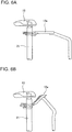
- FIGs. 7 and 8 which are enlarged schematic front and perspective views of the hinge bracket 14 and its peripheral structure, in the vehicle rear seat frame according to the present example, a plate 16 to serve as the first reinforcement member and a bulk head 17 to serve as the second reinforcement member are fixed to the inner side of the recessed section of the side member 25 having a substantially U-shape cross section.
- the frame inside the side member 25 is shown in dashed lines.
- the plate 16 is attached at the vehicle front side of the weak portion E of the side member 25 so as to cover (close) the upper side of the recessed section of the side member 25, and extends along a part of the side member 25.
- the bulk head 17 is formed integrally with the vehicle rear side of the plate 16, and extends toward the bottom side of the recessed section from the plate 16, inside the side member 25.
- the bulk head 17 couples the plate 16 and the bottom side of the recessed section of the side member 25.
- the bulk head 17 is positioned at the vehicle front side of the weak portion E of the side member 25.
- the hinge bracket 14 has a bottom surface 14a fixed to the side member 25 via the plate 16. That is, the plate 16 couples the side member 25 and the hinge bracket 14. Although not shown, the hinge bracket on the opposite side is fixed similarly to the side member 24.
- the hinge bracket 14 is formed and situated so as not to interfere with the side member 25 that deforms in a rear-end collision. That is, specifically, as shown in FIGs. 7 and 8 , the hinge bracket 14 has a side surface 14b and the bottom surface 14a, the shaft 21 penetrating through the upper part of the side surface 14b, and the bottom surface 14a being fixed at the vehicle front side of the weak portion E of the side member 25.
- the plate 16 is disposed between the side member 25 and the hinge bracket 14, at the vehicle front side of the weak portion E of the side member 25.
- the plate 16 and the bulk head 17 restrict movement of the hinge brackets 13, 14 supporting the shaft 21, so that the hinge brackets 13, 14 function as bracing members that promote bending of the seat cushion frame 11 and the seat back frame 12, thus suppressing the movement amount of the seat cushion frame 11 and the seat back frame 12 in a housed state toward the vehicle front side in a rear-end collision, which makes it possible to reduce interference with the high-voltage parts 22.
- the vehicle rear seat frame according to the present example includes a center bracket 15 supporting the center part of the shaft 21 with respect to the extending direction of the shaft 21 (the shaft 21 is disposed so as to penetrate through the center bracket 15).
- the center bracket 15 is fixed to the floor panel 26 of the vehicle of the vehicle V.
- the vehicle rear seat frame it is possible to further suppress the movement amount of the housed seat cushion frame 11 and the seat back frame 12 toward the vehicle front side in a rear-end collision, which makes it possible to reduce interference with the high-voltage parts 22 even further.
- the reinforcement by the hinge brackets 13, 14 also have an effect to suppress separation of the rear seat 10 from the vehicle body due to breakage of a base member (floor panel 26) caused by movement of the center bracket 15 in a rear-end collision.
- the rear seat 10 having the vehicle rear seat frame according to the present example as its internal frame can be properly used in a normal state (non-housed) state, for the direction of the load applied to the seat cushion frame 11 and the seat back frame 12 when the rear seat 10 is used in a normal (non-housed) state is different from the direction of the load applied to the seat cushion frame 11 and the seat back frame 12 in a rear-end collision described above (i.e. the above described weakening direction).
- the seat cushion frame 11 and the seat back frame 12 are housed by being rotated toward the vehicle rear side in the above description, the seat cushion frame 11 and the seat back frame 12 may be housed by being rotated toward the vehicle front side.
- the high-voltage parts 22 need to be disposed at the vehicle front side of the seat cushion frame 11 and the seat back frame 12 in a housed state.
- the high-voltage parts 22 need to be disposed even closer to the front of the vehicle than in a case where the seat cushion frame 11 and the seat back frame 12 are housed by being rotated toward the vehicle rear side.
- components disposed at the vehicle front side of the seat cushion frame 11 and the seat back frame 12 in a housed state are the high-voltage parts 22, the present example is not limited to this.
- the components may be other parts (parts that may a high risk when damaged, such as battery, fuel tank, etc.).
- the present disclosure is applicable as a vehicle rear seat frame.
Landscapes
- Engineering & Computer Science (AREA)
- Aviation & Aerospace Engineering (AREA)
- Transportation (AREA)
- Mechanical Engineering (AREA)
- Seats For Vehicles (AREA)
Claims (9)
- Fahrzeugrücksitzrahmen (10F) für einen Rücksitz, der in einem hinteren Teil eines Fahrzeugs (V) angeordnet ist, mit einem Sitzpolsterrahmen (11) und einem Sitzlehnenrahmen (12), die um eine Achse entlang einer Querrichtung des Fahrzeugs einklappbar sind, um einander zu überlappen, dadurch gekennzeichnet, dass
der Sitzpolsterrahmen einen Sitzpolsterseitenrahmen (11a, 11b) an jedem Seitenende des Sitzpolsterrahmens aufweist, wobei sich der Sitzpolsterseitenrahmen im eingeklappten Zustand in Längsrichtung des Fahrzeugs erstreckt, und
der Sitzlehnenrahmen einen Sitzlehnenseitenrahmen (12a, 12b) an jedem Seitenende des Sitzlehnenrahmens aufweist, wobei sich der Sitzlehnenseitenrahmen im eingeklappten Zustand in Längsrichtung erstreckt,
wobei der Sitzpolsterseitenrahmen einen ersten Schwachstellenabschnitt (A1 bis A3, B1 bis B3) mit niedrigerer Längsfestigkeit als andere Abschnitte davon aufweist und
der Sitzlehnenseitenrahmen einen zweiten Schwachstellenabschnitt (C1 bis C3, D1 bis D3) mit niedrigerer Längsfestigkeit als andere Abschnitte davon aufweist. - Fahrzeugrücksitzrahmen nach Anspruch 1,
wobei der erste Schwachstellenabschnitt und der zweite Schwachstellenabschnitt an Positionen gebildet sind, die einander in senkrechter Richtung überlappen, wenn der Sitzpolsterrahmen (11) und der Sitzlehnenrahmen (12) eingeklappt sind. - Fahrzeugrücksitzrahmen nach Anspruch 1 oder 2,
wobei der erste Schwachstellenabschnitt (A1 bis A3, B1 bis B3) ein Abschnitt des Sitzpolsterseitenrahmens mit einer Form ist, die so konfiguriert ist, dass sie sich bei Aufnahme einer Längslast vom Fahrzeugheck seitlich nach außen biegt, und
der zweite Schwachstellenabschnitt (C1 bis C3, D1 bis D3) ein Abschnitt des Sitzlehnenseitenrahmens mit einer Form ist, die so konfiguriert ist, dass sie sich bei Aufnahme einer Längslast vom Fahrzeugheck seitlich nach außen biegt. - Fahrzeugrücksitzrahmen nach Anspruch 3,
wobei der erste Schwachstellenabschnitt (A1 bis A3, B1 bis B3) und der zweite Schwachstellenabschnitt (C1 bis C3, D1 bis D3) jeweils eine gekrümmte Form haben, die in Seitenrichtung nach außen vorsteht. - Fahrzeugrücksitzrahmen nach Anspruch 4,
wobei der Sitzpolsterrahmen (11) ein Paar der Sitzpolsterseitenrahmen (11a, 11b) und einen Sitzpolsterquerrahmen (11c) aufweist, der sich in Querrichtung erstreckt und jeweilige distale Enden der Sitzpolsterseitenrahmen koppelt, und
der Sitzlehnenrahmen (12) ein Paar der Sitzlehnenseitenrahmen (12a, 12b) und einen Sitzlehnenquerrahmen (12c) aufweist, der sich in Querrichtung erstreckt und jeweilige distale Enden der Sitzlehnenseitenrahmen koppelt,
wobei der erste Schwachstellenabschnitt (A1 bis A3, B1 bis B3) aufweist:einen ersten gekrümmten Abschnitt (A1, B1), der auf einer proximalen Endseite des Sitzpolsterseitenrahmens mit einer Form gebildet ist, die seitlich nach außen gekrümmt ist;einen zweiten gekrümmten Abschnitt (A3, B3), der an einem Koppelabschnitt zwischen einem Seitenende des Sitzpolsterquerrahmens und dem distalen Ende des Sitzpolsterseitenrahmens gebildet ist; undeinen dritten gekrümmten Abschnitt (A2, B2), der zwischen dem ersten gekrümmten Abschnitt und dem zweiten gekrümmten Abschnitt gebildet ist und eine Form hat, die seitlich nach innen gekrümmt ist, undwobei der zweite Schwachstellenabschnitt (C1 bis C3, D1 bis D3) aufweist:einen vierten gekrümmten Abschnitt (C1, D1), der auf einem proximalen Ende des Sitzlehnenseitenrahmens mit einer Form gebildet ist, die seitlich nach außen gekrümmt ist;einen fünften gekrümmten Abschnitt (C3, D3), der an einem Koppelabschnitt zwischen einem Seitenende des Sitzlehnenquerrahmens und dem distalen Ende des Sitzlehnenseitenrahmens gebildet ist; undeinen sechsten gekrümmten Abschnitt (C2, D2), der zwischen dem vierten gekrümmten Abschnitt und dem fünften gekrümmten Abschnitt mit einer Form gebildet ist, die seitlich nach innen gekrümmt ist. - Fahrzeug, das aufweist:ein Paar Seitenteil (24, 25), die sich in Längsrichtung erstrecken und an beiden Seitenenden des Fahrzeugs (V) angeordnet sind; undden Fahrzeugrücksitzrahmen nach einem der Ansprüche 2 bis 5,wobei die Seitenteile einen dritten Schwachstellenabschnitt (E) aufweisen, der so konfiguriert ist, dass er sich bei Aufnahme einer Last in Längsrichtung in Längsrichtung verformt, undder erste Schwachstellenabschnitt, der zweite Schwachstellenabschnitt und der dritte Schwachstellenabschnitt an Positionen gebildet sind, die einander in senkrechter Richtung überlappen, wenn der Sitzpolsterrahmen und der Sitzlehnenrahmen eingeklappt sind.
- Fahrzeug nach Anspruch 6, das ferner aufweist:eine Achse (21), die sich in Querrichtung erstreckt und den Sitzpolsterrahmen und den Sitzlehnenrahmen drehbar stützt;eine Scharnierhalterung (13, 14), die an einer Fahrzeugvorderseite vom dritten Schwachstellenabschnitt des Seitenteils befestigt ist, wobei die Scharnierhalterung (13, 14) ein Ende der Achse stützt; undein erstes Koppelteil (16), das das Seitenteil und die Scharnierhalterung an der Fahrzeugvorderseite vom dritten Schwachstellenabschnitt des Längsträgers koppelt.
- Fahrzeug nach Anspruch 7, ferner mit einem zweiten Koppelteil (17), das innerhalb des Seitenteils und an einer Fahrzeugrückseite vom ersten Koppelteil vorgesehen ist, wobei das zweite Koppelteil das erste Koppelteil und eine Unterseite des Seitenteils koppelt.
- Fahrzeug nach Anspruch 7 oder 8, ferner mit einer Mittelhalterung (15), die an einem Bodenblech des Fahrzeugs befestigt ist und einen in Querrichtung mittleren Teil der Achse stützt.
Applications Claiming Priority (1)
| Application Number | Priority Date | Filing Date | Title |
|---|---|---|---|
| JP2016239034A JP6774026B2 (ja) | 2016-12-09 | 2016-12-09 | 車両後部座席構造 |
Publications (2)
| Publication Number | Publication Date |
|---|---|
| EP3333010A1 EP3333010A1 (de) | 2018-06-13 |
| EP3333010B1 true EP3333010B1 (de) | 2020-05-20 |
Family
ID=60450548
Family Applications (1)
| Application Number | Title | Priority Date | Filing Date |
|---|---|---|---|
| EP17203213.8A Active EP3333010B1 (de) | 2016-12-09 | 2017-11-23 | Fahrzeugrücksitzrahmen und fahrzeug |
Country Status (4)
| Country | Link |
|---|---|
| US (1) | US10604042B2 (de) |
| EP (1) | EP3333010B1 (de) |
| JP (1) | JP6774026B2 (de) |
| CN (1) | CN108215954B (de) |
Families Citing this family (6)
| Publication number | Priority date | Publication date | Assignee | Title |
|---|---|---|---|---|
| JP7298239B2 (ja) * | 2019-03-28 | 2023-06-27 | 三菱自動車工業株式会社 | 車両用シート装置のヘッドレスト移動抑制構造 |
| JP7391089B2 (ja) * | 2019-03-29 | 2023-12-04 | 株式会社タチエス | 車両用シート |
| KR102931341B1 (ko) * | 2019-12-05 | 2026-02-25 | 현대자동차주식회사 | 차량용 차체 |
| US12296666B2 (en) | 2020-01-17 | 2025-05-13 | Mitsubishi Jidosha Kogyo Kabushiki Kaisha | Arrangement structure for power supply unit and rear seat in electric vehicle |
| CN111516569B (zh) * | 2020-04-14 | 2025-02-14 | 广汽零部件有限公司 | 一种能溃缩吸能的汽车后排座椅骨架 |
| JP7424239B2 (ja) * | 2020-07-27 | 2024-01-30 | 三菱自動車工業株式会社 | 車両の後部構造 |
Family Cites Families (13)
| Publication number | Priority date | Publication date | Assignee | Title |
|---|---|---|---|---|
| US3544164A (en) * | 1967-07-24 | 1970-12-01 | Toyota Motor Co Ltd | Seat frame construction |
| JPH03125628U (de) * | 1990-03-31 | 1991-12-18 | ||
| US5499863A (en) * | 1993-05-17 | 1996-03-19 | Toyota Shatai Kabushiki Kaisha | Seat back frame |
| JP3376887B2 (ja) * | 1997-10-13 | 2003-02-10 | トヨタ自動車株式会社 | 車両用シート |
| JP4576780B2 (ja) * | 2001-09-21 | 2010-11-10 | マツダ株式会社 | 車体のフレーム構造及び車体フレームの製造方法 |
| JP3626160B2 (ja) * | 2001-11-19 | 2005-03-02 | 本田技研工業株式会社 | 車両用シート |
| JP4033696B2 (ja) | 2002-03-29 | 2008-01-16 | 株式会社タチエス | 車両用シート装置 |
| US7360832B2 (en) * | 2006-01-12 | 2008-04-22 | Tachi-S Co. Ltd. | Impact absorption structure of vehicle seat |
| JP5176555B2 (ja) * | 2008-01-16 | 2013-04-03 | トヨタ紡織株式会社 | フレーム構造 |
| JP5509917B2 (ja) * | 2010-02-24 | 2014-06-04 | トヨタ紡織株式会社 | 乗物シート用シート高さ調整装置 |
| JP5734812B2 (ja) * | 2011-11-15 | 2015-06-17 | トヨタ自動車株式会社 | 車両用シート |
| JP6017952B2 (ja) | 2012-12-27 | 2016-11-02 | トヨタ紡織株式会社 | 乗物用シート |
| JP2016150661A (ja) * | 2015-02-17 | 2016-08-22 | テイ・エス テック株式会社 | 車両用シート |
-
2016
- 2016-12-09 JP JP2016239034A patent/JP6774026B2/ja active Active
-
2017
- 2017-11-23 EP EP17203213.8A patent/EP3333010B1/de active Active
- 2017-12-05 US US15/832,132 patent/US10604042B2/en active Active
- 2017-12-08 CN CN201711295709.9A patent/CN108215954B/zh active Active
Non-Patent Citations (1)
| Title |
|---|
| None * |
Also Published As
| Publication number | Publication date |
|---|---|
| EP3333010A1 (de) | 2018-06-13 |
| CN108215954B (zh) | 2020-05-15 |
| US10604042B2 (en) | 2020-03-31 |
| CN108215954A (zh) | 2018-06-29 |
| JP6774026B2 (ja) | 2020-10-21 |
| JP2018094974A (ja) | 2018-06-21 |
| US20180162247A1 (en) | 2018-06-14 |
Similar Documents
| Publication | Publication Date | Title |
|---|---|---|
| EP3333010B1 (de) | Fahrzeugrücksitzrahmen und fahrzeug | |
| CN112109811B (zh) | 车身结构和包括该车身结构的车辆 | |
| JP5493897B2 (ja) | 車体後部の下部構造 | |
| JP4207806B2 (ja) | 車体フロア構造 | |
| CN104395149B (zh) | 车身前部结构 | |
| EP2599693A1 (de) | Struktur für den unteren teil einer fahrzeugkarosserie | |
| US20140327268A1 (en) | Vehicle underbody structure | |
| CN102858572B (zh) | 电源装置的保护框架结构 | |
| US20140158567A1 (en) | Reinforcing structure of package tray side member for vehicle | |
| CN104512475B (zh) | 车辆后部构造 | |
| JP2019006311A (ja) | 車体前部構造 | |
| JP2013112058A (ja) | スライドドア | |
| CN107891911B (zh) | 电池包车身一体化结构及汽车 | |
| US20120080907A1 (en) | Vehicle floor frame structure | |
| CN103085615A (zh) | 车辆的牵引用钩的固定部结构 | |
| US12194828B2 (en) | Vehicle body lower section structure | |
| JP2017144955A (ja) | 車体構造 | |
| JP2020083144A (ja) | 車両前部構造 | |
| EP3395653B1 (de) | Struktur eines vorderen fahrzeugabschnitts | |
| CN100482518C (zh) | 车辆的车架结构 | |
| JP2000203451A (ja) | 車両のシャシフレ―ム衝突安全構造 | |
| JP2009056855A (ja) | 車体上部構造 | |
| JP6516799B2 (ja) | 車体構造 | |
| US20180304930A1 (en) | Vechicle front structure | |
| JP5256867B2 (ja) | 車両の後部車体構造 |
Legal Events
| Date | Code | Title | Description |
|---|---|---|---|
| PUAI | Public reference made under article 153(3) epc to a published international application that has entered the european phase |
Free format text: ORIGINAL CODE: 0009012 |
|
| STAA | Information on the status of an ep patent application or granted ep patent |
Free format text: STATUS: REQUEST FOR EXAMINATION WAS MADE |
|
| 17P | Request for examination filed |
Effective date: 20171127 |
|
| AK | Designated contracting states |
Kind code of ref document: A1 Designated state(s): AL AT BE BG CH CY CZ DE DK EE ES FI FR GB GR HR HU IE IS IT LI LT LU LV MC MK MT NL NO PL PT RO RS SE SI SK SM TR |
|
| AX | Request for extension of the european patent |
Extension state: BA ME |
|
| RBV | Designated contracting states (corrected) |
Designated state(s): AL AT BE BG CH CY CZ DE DK EE ES FI FR GB GR HR HU IE IS IT LI LT LU LV MC MK MT NL NO PL PT RO RS SE SI SK SM TR |
|
| RAP1 | Party data changed (applicant data changed or rights of an application transferred) |
Owner name: MITSUBISHI JIDOSHA KOGYO KABUSHIKI KAISHA |
|
| GRAP | Despatch of communication of intention to grant a patent |
Free format text: ORIGINAL CODE: EPIDOSNIGR1 |
|
| STAA | Information on the status of an ep patent application or granted ep patent |
Free format text: STATUS: GRANT OF PATENT IS INTENDED |
|
| RIC1 | Information provided on ipc code assigned before grant |
Ipc: B60N 2/427 20060101ALI20191118BHEP Ipc: B60N 2/30 20060101AFI20191118BHEP Ipc: B60N 2/42 20060101ALI20191118BHEP |
|
| INTG | Intention to grant announced |
Effective date: 20191219 |
|
| GRAS | Grant fee paid |
Free format text: ORIGINAL CODE: EPIDOSNIGR3 |
|
| GRAA | (expected) grant |
Free format text: ORIGINAL CODE: 0009210 |
|
| STAA | Information on the status of an ep patent application or granted ep patent |
Free format text: STATUS: THE PATENT HAS BEEN GRANTED |
|
| AK | Designated contracting states |
Kind code of ref document: B1 Designated state(s): AL AT BE BG CH CY CZ DE DK EE ES FI FR GB GR HR HU IE IS IT LI LT LU LV MC MK MT NL NO PL PT RO RS SE SI SK SM TR |
|
| REG | Reference to a national code |
Ref country code: GB Ref legal event code: FG4D |
|
| REG | Reference to a national code |
Ref country code: CH Ref legal event code: EP |
|
| REG | Reference to a national code |
Ref country code: DE Ref legal event code: R096 Ref document number: 602017016984 Country of ref document: DE |
|
| REG | Reference to a national code |
Ref country code: AT Ref legal event code: REF Ref document number: 1272400 Country of ref document: AT Kind code of ref document: T Effective date: 20200615 |
|
| REG | Reference to a national code |
Ref country code: LT Ref legal event code: MG4D |
|
| REG | Reference to a national code |
Ref country code: NL Ref legal event code: MP Effective date: 20200520 |
|
| PG25 | Lapsed in a contracting state [announced via postgrant information from national office to epo] |
Ref country code: NO Free format text: LAPSE BECAUSE OF FAILURE TO SUBMIT A TRANSLATION OF THE DESCRIPTION OR TO PAY THE FEE WITHIN THE PRESCRIBED TIME-LIMIT Effective date: 20200820 Ref country code: GR Free format text: LAPSE BECAUSE OF FAILURE TO SUBMIT A TRANSLATION OF THE DESCRIPTION OR TO PAY THE FEE WITHIN THE PRESCRIBED TIME-LIMIT Effective date: 20200821 Ref country code: FI Free format text: LAPSE BECAUSE OF FAILURE TO SUBMIT A TRANSLATION OF THE DESCRIPTION OR TO PAY THE FEE WITHIN THE PRESCRIBED TIME-LIMIT Effective date: 20200520 Ref country code: LT Free format text: LAPSE BECAUSE OF FAILURE TO SUBMIT A TRANSLATION OF THE DESCRIPTION OR TO PAY THE FEE WITHIN THE PRESCRIBED TIME-LIMIT Effective date: 20200520 Ref country code: PT Free format text: LAPSE BECAUSE OF FAILURE TO SUBMIT A TRANSLATION OF THE DESCRIPTION OR TO PAY THE FEE WITHIN THE PRESCRIBED TIME-LIMIT Effective date: 20200921 Ref country code: IS Free format text: LAPSE BECAUSE OF FAILURE TO SUBMIT A TRANSLATION OF THE DESCRIPTION OR TO PAY THE FEE WITHIN THE PRESCRIBED TIME-LIMIT Effective date: 20200920 Ref country code: SE Free format text: LAPSE BECAUSE OF FAILURE TO SUBMIT A TRANSLATION OF THE DESCRIPTION OR TO PAY THE FEE WITHIN THE PRESCRIBED TIME-LIMIT Effective date: 20200520 |
|
| PG25 | Lapsed in a contracting state [announced via postgrant information from national office to epo] |
Ref country code: HR Free format text: LAPSE BECAUSE OF FAILURE TO SUBMIT A TRANSLATION OF THE DESCRIPTION OR TO PAY THE FEE WITHIN THE PRESCRIBED TIME-LIMIT Effective date: 20200520 Ref country code: LV Free format text: LAPSE BECAUSE OF FAILURE TO SUBMIT A TRANSLATION OF THE DESCRIPTION OR TO PAY THE FEE WITHIN THE PRESCRIBED TIME-LIMIT Effective date: 20200520 Ref country code: BG Free format text: LAPSE BECAUSE OF FAILURE TO SUBMIT A TRANSLATION OF THE DESCRIPTION OR TO PAY THE FEE WITHIN THE PRESCRIBED TIME-LIMIT Effective date: 20200820 Ref country code: RS Free format text: LAPSE BECAUSE OF FAILURE TO SUBMIT A TRANSLATION OF THE DESCRIPTION OR TO PAY THE FEE WITHIN THE PRESCRIBED TIME-LIMIT Effective date: 20200520 |
|
| REG | Reference to a national code |
Ref country code: AT Ref legal event code: MK05 Ref document number: 1272400 Country of ref document: AT Kind code of ref document: T Effective date: 20200520 |
|
| PG25 | Lapsed in a contracting state [announced via postgrant information from national office to epo] |
Ref country code: AL Free format text: LAPSE BECAUSE OF FAILURE TO SUBMIT A TRANSLATION OF THE DESCRIPTION OR TO PAY THE FEE WITHIN THE PRESCRIBED TIME-LIMIT Effective date: 20200520 Ref country code: NL Free format text: LAPSE BECAUSE OF FAILURE TO SUBMIT A TRANSLATION OF THE DESCRIPTION OR TO PAY THE FEE WITHIN THE PRESCRIBED TIME-LIMIT Effective date: 20200520 |
|
| PG25 | Lapsed in a contracting state [announced via postgrant information from national office to epo] |
Ref country code: ES Free format text: LAPSE BECAUSE OF FAILURE TO SUBMIT A TRANSLATION OF THE DESCRIPTION OR TO PAY THE FEE WITHIN THE PRESCRIBED TIME-LIMIT Effective date: 20200520 Ref country code: CZ Free format text: LAPSE BECAUSE OF FAILURE TO SUBMIT A TRANSLATION OF THE DESCRIPTION OR TO PAY THE FEE WITHIN THE PRESCRIBED TIME-LIMIT Effective date: 20200520 Ref country code: RO Free format text: LAPSE BECAUSE OF FAILURE TO SUBMIT A TRANSLATION OF THE DESCRIPTION OR TO PAY THE FEE WITHIN THE PRESCRIBED TIME-LIMIT Effective date: 20200520 Ref country code: DK Free format text: LAPSE BECAUSE OF FAILURE TO SUBMIT A TRANSLATION OF THE DESCRIPTION OR TO PAY THE FEE WITHIN THE PRESCRIBED TIME-LIMIT Effective date: 20200520 Ref country code: AT Free format text: LAPSE BECAUSE OF FAILURE TO SUBMIT A TRANSLATION OF THE DESCRIPTION OR TO PAY THE FEE WITHIN THE PRESCRIBED TIME-LIMIT Effective date: 20200520 Ref country code: EE Free format text: LAPSE BECAUSE OF FAILURE TO SUBMIT A TRANSLATION OF THE DESCRIPTION OR TO PAY THE FEE WITHIN THE PRESCRIBED TIME-LIMIT Effective date: 20200520 Ref country code: SM Free format text: LAPSE BECAUSE OF FAILURE TO SUBMIT A TRANSLATION OF THE DESCRIPTION OR TO PAY THE FEE WITHIN THE PRESCRIBED TIME-LIMIT Effective date: 20200520 Ref country code: IT Free format text: LAPSE BECAUSE OF FAILURE TO SUBMIT A TRANSLATION OF THE DESCRIPTION OR TO PAY THE FEE WITHIN THE PRESCRIBED TIME-LIMIT Effective date: 20200520 |
|
| REG | Reference to a national code |
Ref country code: DE Ref legal event code: R097 Ref document number: 602017016984 Country of ref document: DE |
|
| PG25 | Lapsed in a contracting state [announced via postgrant information from national office to epo] |
Ref country code: SK Free format text: LAPSE BECAUSE OF FAILURE TO SUBMIT A TRANSLATION OF THE DESCRIPTION OR TO PAY THE FEE WITHIN THE PRESCRIBED TIME-LIMIT Effective date: 20200520 Ref country code: PL Free format text: LAPSE BECAUSE OF FAILURE TO SUBMIT A TRANSLATION OF THE DESCRIPTION OR TO PAY THE FEE WITHIN THE PRESCRIBED TIME-LIMIT Effective date: 20200520 |
|
| PLBE | No opposition filed within time limit |
Free format text: ORIGINAL CODE: 0009261 |
|
| STAA | Information on the status of an ep patent application or granted ep patent |
Free format text: STATUS: NO OPPOSITION FILED WITHIN TIME LIMIT |
|
| 26N | No opposition filed |
Effective date: 20210223 |
|
| PG25 | Lapsed in a contracting state [announced via postgrant information from national office to epo] |
Ref country code: SI Free format text: LAPSE BECAUSE OF FAILURE TO SUBMIT A TRANSLATION OF THE DESCRIPTION OR TO PAY THE FEE WITHIN THE PRESCRIBED TIME-LIMIT Effective date: 20200520 |
|
| PG25 | Lapsed in a contracting state [announced via postgrant information from national office to epo] |
Ref country code: MC Free format text: LAPSE BECAUSE OF FAILURE TO SUBMIT A TRANSLATION OF THE DESCRIPTION OR TO PAY THE FEE WITHIN THE PRESCRIBED TIME-LIMIT Effective date: 20200520 |
|
| REG | Reference to a national code |
Ref country code: CH Ref legal event code: PL |
|
| PG25 | Lapsed in a contracting state [announced via postgrant information from national office to epo] |
Ref country code: LU Free format text: LAPSE BECAUSE OF NON-PAYMENT OF DUE FEES Effective date: 20201123 |
|
| REG | Reference to a national code |
Ref country code: BE Ref legal event code: MM Effective date: 20201130 |
|
| PG25 | Lapsed in a contracting state [announced via postgrant information from national office to epo] |
Ref country code: LI Free format text: LAPSE BECAUSE OF NON-PAYMENT OF DUE FEES Effective date: 20201130 Ref country code: CH Free format text: LAPSE BECAUSE OF NON-PAYMENT OF DUE FEES Effective date: 20201130 |
|
| PG25 | Lapsed in a contracting state [announced via postgrant information from national office to epo] |
Ref country code: IE Free format text: LAPSE BECAUSE OF NON-PAYMENT OF DUE FEES Effective date: 20201123 |
|
| PG25 | Lapsed in a contracting state [announced via postgrant information from national office to epo] |
Ref country code: TR Free format text: LAPSE BECAUSE OF FAILURE TO SUBMIT A TRANSLATION OF THE DESCRIPTION OR TO PAY THE FEE WITHIN THE PRESCRIBED TIME-LIMIT Effective date: 20200520 Ref country code: MT Free format text: LAPSE BECAUSE OF FAILURE TO SUBMIT A TRANSLATION OF THE DESCRIPTION OR TO PAY THE FEE WITHIN THE PRESCRIBED TIME-LIMIT Effective date: 20200520 Ref country code: CY Free format text: LAPSE BECAUSE OF FAILURE TO SUBMIT A TRANSLATION OF THE DESCRIPTION OR TO PAY THE FEE WITHIN THE PRESCRIBED TIME-LIMIT Effective date: 20200520 |
|
| PG25 | Lapsed in a contracting state [announced via postgrant information from national office to epo] |
Ref country code: MK Free format text: LAPSE BECAUSE OF FAILURE TO SUBMIT A TRANSLATION OF THE DESCRIPTION OR TO PAY THE FEE WITHIN THE PRESCRIBED TIME-LIMIT Effective date: 20200520 |
|
| GBPC | Gb: european patent ceased through non-payment of renewal fee |
Effective date: 20211123 |
|
| PG25 | Lapsed in a contracting state [announced via postgrant information from national office to epo] |
Ref country code: BE Free format text: LAPSE BECAUSE OF NON-PAYMENT OF DUE FEES Effective date: 20201130 |
|
| PG25 | Lapsed in a contracting state [announced via postgrant information from national office to epo] |
Ref country code: GB Free format text: LAPSE BECAUSE OF NON-PAYMENT OF DUE FEES Effective date: 20211123 |
|
| PGFP | Annual fee paid to national office [announced via postgrant information from national office to epo] |
Ref country code: FR Payment date: 20250930 Year of fee payment: 9 |
|
| PGFP | Annual fee paid to national office [announced via postgrant information from national office to epo] |
Ref country code: DE Payment date: 20250930 Year of fee payment: 9 |