EP3327738A1 - Transformateur - Google Patents
Transformateur Download PDFInfo
- Publication number
- EP3327738A1 EP3327738A1 EP17202127.1A EP17202127A EP3327738A1 EP 3327738 A1 EP3327738 A1 EP 3327738A1 EP 17202127 A EP17202127 A EP 17202127A EP 3327738 A1 EP3327738 A1 EP 3327738A1
- Authority
- EP
- European Patent Office
- Prior art keywords
- coil
- coil section
- ring
- section
- circuit board
- Prior art date
- Legal status (The legal status is an assumption and is not a legal conclusion. Google has not performed a legal analysis and makes no representation as to the accuracy of the status listed.)
- Granted
Links
- 239000004020 conductor Substances 0.000 claims abstract description 26
- 239000011347 resin Substances 0.000 claims abstract description 24
- 229920005989 resin Polymers 0.000 claims abstract description 24
- 238000003780 insertion Methods 0.000 claims abstract description 18
- 230000037431 insertion Effects 0.000 claims abstract description 18
- RYGMFSIKBFXOCR-UHFFFAOYSA-N Copper Chemical compound [Cu] RYGMFSIKBFXOCR-UHFFFAOYSA-N 0.000 claims description 4
- 238000009413 insulation Methods 0.000 description 7
- 238000000034 method Methods 0.000 description 3
- 238000006243 chemical reaction Methods 0.000 description 2
- 230000008878 coupling Effects 0.000 description 2
- 238000010168 coupling process Methods 0.000 description 2
- 238000005859 coupling reaction Methods 0.000 description 2
- 239000000696 magnetic material Substances 0.000 description 2
- 239000000463 material Substances 0.000 description 2
- 230000001629 suppression Effects 0.000 description 2
- 229910000859 α-Fe Inorganic materials 0.000 description 2
- 230000000694 effects Effects 0.000 description 1
- 230000005611 electricity Effects 0.000 description 1
- 230000004907 flux Effects 0.000 description 1
- 239000010410 layer Substances 0.000 description 1
- 238000010248 power generation Methods 0.000 description 1
- 230000005855 radiation Effects 0.000 description 1
- 239000002356 single layer Substances 0.000 description 1
Images


Classifications
-
- H—ELECTRICITY
- H01—ELECTRIC ELEMENTS
- H01F—MAGNETS; INDUCTANCES; TRANSFORMERS; SELECTION OF MATERIALS FOR THEIR MAGNETIC PROPERTIES
- H01F27/00—Details of transformers or inductances, in general
- H01F27/28—Coils; Windings; Conductive connections
- H01F27/32—Insulating of coils, windings, or parts thereof
- H01F27/324—Insulation between coil and core, between different winding sections, around the coil; Other insulation structures
-
- H—ELECTRICITY
- H01—ELECTRIC ELEMENTS
- H01F—MAGNETS; INDUCTANCES; TRANSFORMERS; SELECTION OF MATERIALS FOR THEIR MAGNETIC PROPERTIES
- H01F27/00—Details of transformers or inductances, in general
- H01F27/28—Coils; Windings; Conductive connections
- H01F27/2823—Wires
-
- H—ELECTRICITY
- H01—ELECTRIC ELEMENTS
- H01F—MAGNETS; INDUCTANCES; TRANSFORMERS; SELECTION OF MATERIALS FOR THEIR MAGNETIC PROPERTIES
- H01F27/00—Details of transformers or inductances, in general
- H01F27/28—Coils; Windings; Conductive connections
- H01F27/2804—Printed windings
-
- H—ELECTRICITY
- H01—ELECTRIC ELEMENTS
- H01F—MAGNETS; INDUCTANCES; TRANSFORMERS; SELECTION OF MATERIALS FOR THEIR MAGNETIC PROPERTIES
- H01F27/00—Details of transformers or inductances, in general
- H01F27/006—Details of transformers or inductances, in general with special arrangement or spacing of turns of the winding(s), e.g. to produce desired self-resonance
-
- H—ELECTRICITY
- H01—ELECTRIC ELEMENTS
- H01F—MAGNETS; INDUCTANCES; TRANSFORMERS; SELECTION OF MATERIALS FOR THEIR MAGNETIC PROPERTIES
- H01F27/00—Details of transformers or inductances, in general
- H01F27/24—Magnetic cores
- H01F27/26—Fastening parts of the core together; Fastening or mounting the core on casing or support
- H01F27/266—Fastening or mounting the core on casing or support
-
- H—ELECTRICITY
- H01—ELECTRIC ELEMENTS
- H01F—MAGNETS; INDUCTANCES; TRANSFORMERS; SELECTION OF MATERIALS FOR THEIR MAGNETIC PROPERTIES
- H01F27/00—Details of transformers or inductances, in general
- H01F27/28—Coils; Windings; Conductive connections
- H01F27/2847—Sheets; Strips
-
- H—ELECTRICITY
- H01—ELECTRIC ELEMENTS
- H01F—MAGNETS; INDUCTANCES; TRANSFORMERS; SELECTION OF MATERIALS FOR THEIR MAGNETIC PROPERTIES
- H01F27/00—Details of transformers or inductances, in general
- H01F27/28—Coils; Windings; Conductive connections
- H01F27/32—Insulating of coils, windings, or parts thereof
- H01F27/323—Insulation between winding turns, between winding layers
-
- H—ELECTRICITY
- H01—ELECTRIC ELEMENTS
- H01F—MAGNETS; INDUCTANCES; TRANSFORMERS; SELECTION OF MATERIALS FOR THEIR MAGNETIC PROPERTIES
- H01F27/00—Details of transformers or inductances, in general
- H01F27/28—Coils; Windings; Conductive connections
- H01F27/32—Insulating of coils, windings, or parts thereof
- H01F27/327—Encapsulating or impregnating
-
- H—ELECTRICITY
- H05—ELECTRIC TECHNIQUES NOT OTHERWISE PROVIDED FOR
- H05K—PRINTED CIRCUITS; CASINGS OR CONSTRUCTIONAL DETAILS OF ELECTRIC APPARATUS; MANUFACTURE OF ASSEMBLAGES OF ELECTRICAL COMPONENTS
- H05K1/00—Printed circuits
- H05K1/18—Printed circuits structurally associated with non-printed electric components
- H05K1/182—Printed circuits structurally associated with non-printed electric components associated with components mounted in the printed circuit board, e.g. insert mounted components [IMC]
- H05K1/183—Components mounted in and supported by recessed areas of the printed circuit board
-
- H—ELECTRICITY
- H01—ELECTRIC ELEMENTS
- H01F—MAGNETS; INDUCTANCES; TRANSFORMERS; SELECTION OF MATERIALS FOR THEIR MAGNETIC PROPERTIES
- H01F27/00—Details of transformers or inductances, in general
- H01F27/28—Coils; Windings; Conductive connections
- H01F27/2804—Printed windings
- H01F2027/2809—Printed windings on stacked layers
-
- H—ELECTRICITY
- H01—ELECTRIC ELEMENTS
- H01F—MAGNETS; INDUCTANCES; TRANSFORMERS; SELECTION OF MATERIALS FOR THEIR MAGNETIC PROPERTIES
- H01F27/00—Details of transformers or inductances, in general
- H01F27/28—Coils; Windings; Conductive connections
- H01F27/2804—Printed windings
- H01F2027/2819—Planar transformers with printed windings, e.g. surrounded by two cores and to be mounted on printed circuit
-
- H—ELECTRICITY
- H01—ELECTRIC ELEMENTS
- H01F—MAGNETS; INDUCTANCES; TRANSFORMERS; SELECTION OF MATERIALS FOR THEIR MAGNETIC PROPERTIES
- H01F27/00—Details of transformers or inductances, in general
- H01F27/28—Coils; Windings; Conductive connections
- H01F27/2847—Sheets; Strips
- H01F2027/2861—Coil formed by folding a blank
Definitions
- the present invention relates to a transformer.
- Japanese Patent Application Publication No. 2008-004823 discloses a transformer having a structure that holds primary coils formed of conductor patterns on a printed circuit board between secondary coils formed of ring-shaped conductor plates.
- the present invention provides a transformer having a structure capable of reducing the number of components, and also reducing man-hours of component assembly, while securing electric insulation between a primary coil and a secondary coil.
- a transformer of a first aspect of the present invention includes: a first coil section formed around a insertion hole provided on a circuit board by coiling a conductor pattern by one round or more in a planar state; a second coil section that includes a first ring composed of a coil formed by coiling a conductor plate by one round or more, the coil being covered with an electric-insulating resin, the first ring being annular and being arranged on a first surface of the circuit board such that a core of the first ring coincides with a core of the first coil section, a second ring composed of a coil formed by coiling a conductor plate by one round or more, the coil being covered with the electric-insulating resin, the second ring being annular and being arranged on a second surface of the circuit board such that a core of the second ring coincides with the core of the first coil section, and a coupled part formed by covering a coupled position between the first ring and the second ring with the electric-insulating resin; and core sections inserted through the insertion
- the second coil section there is employed a shape formed by coupling the annular first ring composed of a coil covered with the electric insulating resin and the annular second ring composed of a coil covered with the electric insulating resin to each other.
- the core sections that are magnetic cores through respective holes extending through the first ring and the second ring after being resin-molded so that the core sections can be fixed.
- the second coil section (one of the primary coil and the secondary coil) is covered with the electric-insulating resin.
- the circuit board may include a slit, the coupled part being inserted and fitted into the slit so as to position the first coil section and the second coil section such that the core of the first coil section coincides with a core of the second coil section.
- the circuit board when the second coil section is assemble to the circuit board where the first coil section is formed, the circuit board is provided with the slit for positioning the first coil section and the second coil section such that the core of the first coil section coincides with the core of the second coil section.
- a part (the coupled part) where the first ring and the second ring of the second coil section are coupled to each other is inserted and fitted into the slit of the circuit board until the coupled position abuts to the end portion of the slit.
- the assembling work with less components allows the core of the first coil section and the core of the second coil section to readily coincide with each other, and to secure coaxial accuracy of the holes into which the core sections are inserted, that is, coaxial accuracy between the through-hole of the circuit board and the through hole of the second coil section. Accordingly, it is possible to enhance assemblability of the core section after the second coil section is fixed to the circuit board.
- the conductor plate may be a rectangular copper wire.
- the circuit board may be disposed in the gap.
- the transformer of the present invention it is possible to reduce the number of components, and also reduce man-hours of component assembly, while securing electric insulation between the primary coil and the secondary coil.
- a transformer of the present invention is configured such that each of air core coils around which a coil wire (conductor plate) is coiled is covered with an electric-insulating resin in a manner as to have a hole through which a core as a magnetic core is to be inserted.
- coil components after being resin-molded can be fixed by inserting cores thereof as magnetic cores through the holes.
- This configuration eliminates necessity of preparing a bobbin around which the coil wire is coiled as a separate component. Accordingly, it is possible to reduce the number of components of the transformer, and also reduce man-hours of component assembly.
- each of components composing the transformer 1 according to one embodiment of the present invention will be described.
- FIG. 1 is a view explaining the structure of the transformer 1 according to one embodiment of the present invention with the components of the transformer developed.
- the transformer 1 exemplified in FIG. 1 is composed of the following components: a circuit board 10 where a first coil section 11 is formed, a second coil section 20, an upper core section 30, and a lower core section 40.
- FIG. 2 is a view explaining a more detailed structure of the second coil section 20 in FIG. 1 .
- the transformer 1 is formed by assembling the following components: the second coil section 20, the upper core section 30, and the lower core section 40, respectively to the circuit board 10 (the first coil section 11) in numerical order indicated in respective arrows from respective directions of these arrows shown in FIG. 1 . This assembling method will be described later.
- the transformer 1 assembled in this manner becomes an element having a structure in which the first coil section 11 and the second coil section 20 are magnetically coupled with each other via the upper core section 30 and the lower core section 40.
- the circuit board 10 is a print circuit board on which conductor patterns allowing electricity to flow therethrough are printed, and wire-connects surface mounted components and others by the conductor patterns so as to configure a predetermined electric circuit.
- This circuit board 10 may have a multiple layer structure or a single layer structure.
- the circuit board 10 is provided with an insertion hole 12a through which a center leg portion 40a of the lower core section 40 described later is inserted, an insertion hole 12b through which an outer leg portion 40b of the lower core section 40 is inserted, and an insertion hole 12c through which an outer leg portion 40c of the lower core section 40 is inserted, respectively.
- a conductor pattern in a coil shape is so formed as to be coiled around the insertion hole 12a of the circuit board 10 by one round or more in a planar state. If the circuit board 10 has a multiple layer structure, a coiled conductor pattern may be formed in each layer. The first coil section 11 formed by this coiled conductor pattern composes a coil on a higher-voltage side in the transformer 1.
- the circuit board 10 is provided with a slit 13 into which a coupled part 24c of the second coil section 20 described later is inserted.
- This slit 13 is formed to facilitate positioning of the first coil section 11 and the second coil section 20 such that cores thereof coincide with each other by inserting and fitting the coupled part 24c into the slit 13 until the coupled part 24c abuts to an end portion 13w located at an innermost position of the slit 13.
- circuit board 10 is provided with screw holes 14n, 15n used for fixing and connecting, to the circuit board 10, a first connecting terminal 21t and a second connecting terminal 22t of the second coil section 20 in which the coupled part 24c is inserted and fitted to the slit 13.
- the second coil section 20 composes a coil on a lower-voltage side of the transformer 1.
- This second coil section 20 has a structure (resin-mold structure) in which a conductor formed by connecting two coils 21 and 22 to each other at a coupled position 23 is covered with a resin (electric-insulating resin) 24 having an electric insulation property, as shown in FIG. 2 .
- Each of the coil 21 and the coil 22 is an air core coil formed of a conductor plate such as a rectangular copper wire, coiled by one round (edgewise coil), for example.
- the coil 21 and the coil 22 are formed with the same coil inner diameter and the same coil outer diameter.
- the coil 21 and the coil 22 are electrically coupled to each other at a coupled position 23 such that both cores thereof coincide with each other, in substantially parallel to each other with a predetermined distance therebetween.
- the predetermined distance is designed to be any dimension that allows a predetermined gap 24g to be formed between a first ring 24u and a second ring 24d that are covered with the electric-insulating resin 24 described later.
- the first connecting terminal 21t extending to the outside of the electric-insulating resin 24 is connected to the coil 21.
- This first connecting terminal 21t is provided with a screw hole 21n.
- a second connecting terminal 22t extending to the outside of the electric-insulating resin 24 is connected to the coil 22.
- This second connecting terminal 22t is provided with a screw hole 22n.
- the coil 21 is covered with the electric-insulating resin 24 so as to have a predetermined thickness around the circumference of the coil 21, to thereby form the annular first ring 24u having a through-hole inside the coil.
- the coil 22 is so covered with the electric-insulating resin 24 as to have a predetermined thickness around the circumference of the coil 22, to thereby form the annular second ring 24d having a through-hole inside the coil.
- the coupled position 23 where the coil 21 and the coil 22 are coupled to each other is covered with the electric-insulating resin 24 so as to have a predetermined thickness around the circumference of the coupled position 23, to thereby form a coupled part 24c.
- the coil 21 and the coil 22 are molded in a manner as to form the predetermined gap 24g between the first ring 24u and the second ring 24d.
- the predetermined gap 24g is designed to have a dimension that allows the circuit board 10 to be inserted thereinto (a thickness equal to or greater than that of the circuit board 10).
- the coupled position 23 is molded such that the coupled part 24c has a thickness not greater than the width of the slit 13 provided to the circuit board 10.
- a pair of V-shaped first guide ribs 24ur between which the upper core section 30 is to be fitted and fixed is erected on a surface of the first ring 24u opposite to the gap 24g.
- the first guide ribs 24ur are formed in a manner as to correspond to the outer shape of the upper core section 30 so that inner surfaces facing each other of the first guide ribs 24ur are engaged with side surfaces of the upper core section 30.
- a pair of V-shaped second guide ribs 24dr between which the lower core section 40 is to be fitted and fixed is erected on a surface of the second ring 24d opposite to the gap 24g.
- These second guide ribs 24dr are formed in a manner as to correspond to the outer shape of the lower core section 40 so that inner surfaces facing each other of the second guide ribs 24dr are engaged with side surfaces of the lower core section 40.
- each of the coil 21 and the coil 22 is formed by coiling the conductor plate by one round.
- each of the coil 21 and the coil 22 may be formed by coiling the conductor plate by two rounds or more, or the coil 21 and the coil 22 may have different coiling rounds from each other.
- the upper core section 30 is a so-called I-shaped core that is in a flat plate-like and butterfly shape in a plan view, and is made of a magnetic material such as a ferrite material, for example.
- the upper core section 30 is formed to have one pair of side surfaces whose center portions are recessed so as to be engaged with the pair of first guide ribs 24ur erected on the surface of the first ring 24u of the second coil section 20.
- the lower core section 40 is a so-called E-shaped core that is made of a magnetic material such as a ferrite material, and has a main body 40p in a flat plate-like and butterfly shape in a plan view, the center leg portion 40a, the outer leg portion 40b, and the outer leg portion 40c.
- the main body 40p is formed to have one pair of side surfaces whose center portions are recessed so as to be engaged with the pair of second guide ribs 24dr erected on the surface of the second ring 24d of the second coil section 20.
- the outer leg portion 40b is erected at one longitudinal end of the main body 40p such that the outer leg portion 40b can be inserted through the insertion hole 12b of the circuit board 10.
- the outer leg portion 40c is erected at the other longitudinal end of the main body 40p such that the outer leg portion 40c can be inserted through the insertion hole 12c of the circuit board 10.
- the center leg portion 40a is erected between the outer leg portion 40b and the outer leg portion 40c such that the center leg portion 40a can be inserted through the insertion hole 12a.
- the center leg portion 40a, the outer leg portion 40b, and the outer leg portion 40c are formed from the main body 40p at the same height so that respective end surfaces thereof become parallel to the main body 40p.
- a closed magnetic circuit (closed magnetic path) through which a magnetic flux passing through the coiled wire of the first coil section 11 and the coiled wire of the second coil section 20 passes is formed by the center leg portion 40a and the outer leg portion 40b, and center leg portion 40a and the outer leg portion 40c.
- the second coil section 20 is assembled to the circuit board 10 from the direction indicated by the arrow (1) in FIG. 1 .
- the coupled part 24c is inserted into the slit 13 while the circuit board 10 is inserted into the gap 24g between the first ring 24u and the second ring 24d.
- the second coil section 20 is inserted until the coupled part 24c abuts to the end portion 13w located at the innermost position of the slit 13.
- the first ring 24u of the second coil section 20 is arranged on one surface (in the upward direction of the drawing) of the circuit board 10 in such a manner that the core of the first ring 24u coincides with the core of the first coil section 11; and the second ring 24d of the second coil section 20 is arranged on the other surface (in the downward direction of the drawing) of the circuit board 10 in such a manner that the core of the second ring 24d coincides with the core of the first coil section 11.
- the second coil section 20 is positioned relative to the circuit board 10 such that the core of the first coil section 11 formed on the circuit board 10 and the core of the second coil section 20 coincide with each other.
- the screw holes 14n and 15n provided to the circuit board 10 coincide with the screw holes 21n and 22n provided respectively to the first connecting terminal 21t and the second connecting terminal 22t of the second coil section 20, and thus screw clamp can be carried out.
- the lower core section 40 is assembled to the circuit board 10 to which the second coil section 20 is assembled, from the direction indicated by the arrow (2) in FIG. 1 , that is, from a direction where the second ring 24d of the second coil section 20 is located.
- the side surfaces of the lower core section 40 are fitted so as to be engaged with the pair of guide ribs 24dr erected on the surface of the second ring 24d of the second coil section 20, to thereby insert the center leg portion 40a of the lower core section 40 into the insertion hole 12a of the circuit board 10, the outer leg portion 40b of the lower core section 40 into the insertion hole 12b of the circuit board 10, and the outer leg portion 40c of the lower core section 40 into the insertion hole 12c of the circuit board 10, respectively.
- the upper core section 30 is assembled to the circuit board 10 where the second coil section 20 and the lower core section 40 have already been assembled, from the direction indicated by the arrow (3) in FIG. 1 , that is, from the direction where the first ring 24u of the second coil section 20 is located.
- the side surface of the upper core section 30 is fitted to be engaged with the pair of first guide ribs 24ur erected on the surface of the first ring 24u of the second coil section 20.
- the respective end surfaces of the center leg portion 40a, the outer leg portion 40b, and the outer leg portion 40c of the lower core section 40 are joined to one flat surface of the upper core section 30. Accordingly, it is possible to form the closed magnetic circuit that magnetically couples the first coil section 11 and the second coil section 20 to each other, by the upper core section 30 and the lower core section 40.
- the structure of the transformer 1 in a state in which the circuit board 10 (the first coil section 11), the second coil section 20, the upper core section 30, and the lower core section 40 are assembled in the above manner will be described.
- FIG. 3 is a perspective view showing a state of the transformer 1 formed by assembling the respective components.
- FIG. 4 is a view of the transformer 1 in FIG. 3 , as viewed from a point A in the arrow direction.
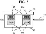
- FIG. 5 is a view of the transformer 1 in FIG. 3 , taken along V-V line and as viewed in the arrow direction.
- the transformer 1 to which the respective components are assembled and mounted to the circuit board 10 has a total thickness by summing the thickness of the upper core section 30 and the thickness of the lower core section 40.
- the circuit board 10 is held by the first ring 24u of the second coil section 20 and the second ring 24d of the second coil section 20.
- the coupled part 24c of the second coil section 20 is inserted in the slit 13 of the circuit board 10.
- the second coil section 20 having a shape such that the annular first ring 24u having a through-hole and composed of the coil 21 covered with the electric-insulating resin 24, and the annular second ring 24d having a through-hole and composed of the coil 22 covered with the electric-insulating resin 24 are coupled at the coupled part 24c.
- the upper core section 30 and the lower core section 40 that are the magnetic cores can be inserted into and fixed to the through-holes of the first ring 24u and the second ring 24d after being resin-molded. Through this, it becomes unnecessary to prepare a bobbin around which the coil wire is coiled as a different component. Hence, it is possible to reduce the number of components of the transformer 1, and also reduce man-hours of component assembly.
- the second coil section 20 is covered with the electric-insulating resin 24. Through this, it is possible to secure electric insulation between the first coil section 11 and the second coil section 20 required for the transformer 1 while the second coil section 20 is assembled to the first coil section 11 formed on the circuit board 10.
- each of the coil 21 and the coil 22 that are the conductor of the second coil section 20 are formed by a conductor plate having a wider width such as a rectangular copper wire.
- the first coil section 11 is formed by utilizing the conductor pattern on the circuit board 10 coiled around the insertion hole 12a by one round or more in a planar state. Through this, the first coil section 11 can be set by using a multiple-round wire; thus it is possible to configure the transformer 1 having a coiling ratio depending on the high voltage conversion rate.
- the coupled part 24c between the first ring 24u and the second ring 24d of the second coil section is inserted and fitted into the slit 13 until the coupled part 24c abuts to the end portion 13w of the slit 13 formed in the circuit board 10, to thereby position the first coil section 11 and the second coil section 20 to each other.
- the circuit board 10 is inserted into the gap 24g of the second coil section 20 so as to assemble the first coil section 11 and the second coil section 20 to each other. That is, this is a structure that holds the first coil section 11 between the first ring 24u and the second ring 24d of the second coil section 20. With this structure, there is a possibility to reduce the dimension of the transformer 1 (particularly, a total thickness thereof when the first coil section 11 and the second coil section 20 are held by the upper core section 30 and the lower core section 40). Since the magnetic coupling between first coil section 11 and the second coil section 20 can be tight, to thereby reduce the number of components such as a radiation mechanism for heat suppression and electronic components for suppressing electric stress (surge), and others.
- the transformer 1 it is possible to freely design how many first coil sections 11 on the higher-voltage side are used, or which of the first coil section 11 on the higher-voltage side and the second coil section 20 on the lower-voltage side is set to be the primary coil or the secondary coil.
- the circuit board 10 having a multiple layer structure may be used so as to configure three first coil sections 11.
- a step-up transformer may be configured such that the primary coil of the transformer 1 is composed of the second coil section 20 as the lower-voltage side, and the secondary coil of the transformer 1 is composed of the first coil section 11 as the higher-voltage side.
- a step-down transformer may be configured such that the primary coil of the transformer 1 is composed of the first coil section 11 as the higher-voltage side, and the secondary coil of the transformer 1 is composed of the second coil section 20 as the lower-voltage side.
- the transformer of the present invention is usable in a solar power generation system, for example, and is useful particularly in the case in which it is desired to reduce the number of components and man-hours of component assembly while securing the electric insulation between the primary coil and the secondary coil.
Landscapes
- Engineering & Computer Science (AREA)
- Power Engineering (AREA)
- Microelectronics & Electronic Packaging (AREA)
- Coils Or Transformers For Communication (AREA)
- Coils Of Transformers For General Uses (AREA)
- Insulating Of Coils (AREA)
Applications Claiming Priority (1)
| Application Number | Priority Date | Filing Date | Title |
|---|---|---|---|
| JP2016226945A JP6572871B2 (ja) | 2016-11-22 | 2016-11-22 | トランス装置およびその組み立て方法 |
Publications (2)
| Publication Number | Publication Date |
|---|---|
| EP3327738A1 true EP3327738A1 (fr) | 2018-05-30 |
| EP3327738B1 EP3327738B1 (fr) | 2021-06-16 |
Family
ID=60331518
Family Applications (1)
| Application Number | Title | Priority Date | Filing Date |
|---|---|---|---|
| EP17202127.1A Active EP3327738B1 (fr) | 2016-11-22 | 2017-11-16 | Transformateur |
Country Status (13)
| Country | Link |
|---|---|
| US (1) | US10535461B2 (fr) |
| EP (1) | EP3327738B1 (fr) |
| JP (1) | JP6572871B2 (fr) |
| KR (1) | KR102016225B1 (fr) |
| CN (1) | CN108091472B (fr) |
| AU (1) | AU2017261482B2 (fr) |
| BR (1) | BR102017024213A2 (fr) |
| CA (1) | CA2985924C (fr) |
| MX (1) | MX2017014984A (fr) |
| MY (1) | MY186543A (fr) |
| PH (1) | PH12017050114B1 (fr) |
| RU (1) | RU2679009C1 (fr) |
| TW (1) | TWI637410B (fr) |
Cited By (2)
| Publication number | Priority date | Publication date | Assignee | Title |
|---|---|---|---|---|
| DE102018221125A1 (de) * | 2018-12-06 | 2020-06-10 | Zf Friedrichshafen Ag | Abstandshalter für einen Planartransformator, Planartransformator mit dem Abstandshalter, Stromverdoppleranordnung mit dem Planartransformator sowie Verfahren zur Montage des Planartransformators |
| EP3817017A4 (fr) * | 2018-06-29 | 2022-02-23 | Shindengen Electric Manufacturing Co., Ltd. | Élément magnétique |
Families Citing this family (8)
| Publication number | Priority date | Publication date | Assignee | Title |
|---|---|---|---|---|
| DE102018213174A1 (de) * | 2018-08-07 | 2019-11-07 | Conti Temic Microelectronic Gmbh | Transformator, Gleichspannungswandler mit einem Transformator |
| KR102174306B1 (ko) * | 2018-10-10 | 2020-11-04 | 이주열 | 성능 개선을 위한 절연 구조가 적용된 평면 트랜스포머 |
| RU200384U1 (ru) * | 2019-06-10 | 2020-10-21 | Общество с ограниченной ответственностью "АЕДОН" | Импульсный трансформатор малой мощности |
| US11164694B2 (en) * | 2019-09-27 | 2021-11-02 | Apple Inc. | Low-spurious electric-field inductor design |
| US12057255B2 (en) * | 2019-12-02 | 2024-08-06 | Acleap Power Inc. | Hybrid transformers for power supplies |
| CN114078623A (zh) * | 2020-08-20 | 2022-02-22 | Tdk株式会社 | 线圈部件以及搭载其的开关电源装置 |
| CN112248330B (zh) * | 2020-10-12 | 2022-08-26 | 中车株洲电机有限公司 | 一种用于变压器下部双出线线圈浇注的方法及底板结构 |
| CN114244073B (zh) * | 2021-12-18 | 2023-07-21 | 北京动力源科技股份有限公司 | 扩电压环形变压器及其与谐振变换器的磁集成结构和方法 |
Citations (5)
| Publication number | Priority date | Publication date | Assignee | Title |
|---|---|---|---|---|
| DE19725865A1 (de) * | 1996-06-21 | 1998-01-02 | Toko Inc | Transformatorwicklungsstruktur |
| EP0961303A2 (fr) * | 1998-05-26 | 1999-12-01 | Artesyn Technologies | Dispositif transformateur |
| JP2008004823A (ja) | 2006-06-23 | 2008-01-10 | Tdk Corp | コイル装置、トランスおよびスイッチング電源 |
| US7414510B1 (en) * | 2007-12-17 | 2008-08-19 | Kuan Tech (Shenzhen) Co., Ltd. | Low-profile planar transformer |
| KR101590132B1 (ko) * | 2015-07-31 | 2016-02-01 | 삼성전기주식회사 | 트랜스포머, 및 판상 코일 성형체 |
Family Cites Families (18)
| Publication number | Priority date | Publication date | Assignee | Title |
|---|---|---|---|---|
| GB2252208B (en) | 1991-01-24 | 1995-05-03 | Burr Brown Corp | Hybrid integrated circuit planar transformer |
| JP2003151838A (ja) * | 2001-11-13 | 2003-05-23 | Murata Mfg Co Ltd | コイル装置およびそれを搭載したモジュール部品 |
| JP4059396B2 (ja) * | 2003-03-31 | 2008-03-12 | Tdk株式会社 | 薄型大電流トランス |
| JP4189745B2 (ja) | 2003-07-24 | 2008-12-03 | 株式会社デンソー | チョークコイル及びトランス並びにこれらの製造方法 |
| RU2345510C1 (ru) * | 2007-09-06 | 2009-01-27 | Яков Аронович Гофман | Способ изготовления планарного трансформатора на основе многослойной печатной платы |
| US8421571B2 (en) * | 2009-02-13 | 2013-04-16 | Mitsubishi Electric Corporation | Transformer |
| JP2012104724A (ja) * | 2010-11-12 | 2012-05-31 | Panasonic Corp | インダクタ部品 |
| JP5413445B2 (ja) * | 2011-03-29 | 2014-02-12 | 株式会社デンソー | トランス |
| JP2013042021A (ja) | 2011-08-18 | 2013-02-28 | Nagano Japan Radio Co | コイル部品及びその製造方法 |
| JP6030828B2 (ja) | 2011-10-19 | 2016-11-24 | 株式会社タムラ製作所 | トランス |
| CN103137305B (zh) | 2011-12-01 | 2016-12-21 | 台达电子企业管理(上海)有限公司 | 一种变压器导电结构及变压器 |
| DE102012111069A1 (de) | 2012-11-16 | 2014-05-22 | Phoenix Contact Gmbh & Co. Kg | Planarübertrager |
| US20140292471A1 (en) | 2013-04-02 | 2014-10-02 | Bao Hui Science & Technology Co., Ltd. | Transformer |
| JP6330311B2 (ja) * | 2013-12-17 | 2018-05-30 | Tdk株式会社 | 巻線部品及び電源装置 |
| JP6388770B2 (ja) | 2014-01-21 | 2018-09-12 | Fdk株式会社 | 巻線部品 |
| KR101475677B1 (ko) * | 2014-09-11 | 2014-12-23 | 삼성전기주식회사 | 코일 부품 및 이를 포함하는 전원공급장치 |
| JP2015026867A (ja) | 2014-10-31 | 2015-02-05 | 株式会社豊田自動織機 | 誘導機器 |
| JP6344797B2 (ja) | 2014-12-26 | 2018-06-20 | オムロンオートモーティブエレクトロニクス株式会社 | 回路基板モジュール |
-
2016
- 2016-11-22 JP JP2016226945A patent/JP6572871B2/ja active Active
-
2017
- 2017-11-09 US US15/808,396 patent/US10535461B2/en active Active
- 2017-11-10 MY MYPI2017704284A patent/MY186543A/en unknown
- 2017-11-10 BR BR102017024213-7A patent/BR102017024213A2/pt not_active Application Discontinuation
- 2017-11-13 TW TW106139118A patent/TWI637410B/zh not_active IP Right Cessation
- 2017-11-13 CN CN201711115559.9A patent/CN108091472B/zh active Active
- 2017-11-14 AU AU2017261482A patent/AU2017261482B2/en not_active Ceased
- 2017-11-14 KR KR1020170151279A patent/KR102016225B1/ko active IP Right Grant
- 2017-11-14 RU RU2017139518A patent/RU2679009C1/ru active
- 2017-11-16 EP EP17202127.1A patent/EP3327738B1/fr active Active
- 2017-11-17 CA CA2985924A patent/CA2985924C/fr not_active Expired - Fee Related
- 2017-11-22 MX MX2017014984A patent/MX2017014984A/es active IP Right Grant
- 2017-11-22 PH PH12017050114A patent/PH12017050114B1/en unknown
Patent Citations (5)
| Publication number | Priority date | Publication date | Assignee | Title |
|---|---|---|---|---|
| DE19725865A1 (de) * | 1996-06-21 | 1998-01-02 | Toko Inc | Transformatorwicklungsstruktur |
| EP0961303A2 (fr) * | 1998-05-26 | 1999-12-01 | Artesyn Technologies | Dispositif transformateur |
| JP2008004823A (ja) | 2006-06-23 | 2008-01-10 | Tdk Corp | コイル装置、トランスおよびスイッチング電源 |
| US7414510B1 (en) * | 2007-12-17 | 2008-08-19 | Kuan Tech (Shenzhen) Co., Ltd. | Low-profile planar transformer |
| KR101590132B1 (ko) * | 2015-07-31 | 2016-02-01 | 삼성전기주식회사 | 트랜스포머, 및 판상 코일 성형체 |
Cited By (2)
| Publication number | Priority date | Publication date | Assignee | Title |
|---|---|---|---|---|
| EP3817017A4 (fr) * | 2018-06-29 | 2022-02-23 | Shindengen Electric Manufacturing Co., Ltd. | Élément magnétique |
| DE102018221125A1 (de) * | 2018-12-06 | 2020-06-10 | Zf Friedrichshafen Ag | Abstandshalter für einen Planartransformator, Planartransformator mit dem Abstandshalter, Stromverdoppleranordnung mit dem Planartransformator sowie Verfahren zur Montage des Planartransformators |
Also Published As
| Publication number | Publication date |
|---|---|
| AU2017261482A1 (en) | 2018-06-07 |
| RU2679009C1 (ru) | 2019-02-05 |
| PH12017050114A1 (en) | 2018-08-06 |
| CN108091472A (zh) | 2018-05-29 |
| EP3327738B1 (fr) | 2021-06-16 |
| US10535461B2 (en) | 2020-01-14 |
| CA2985924C (fr) | 2019-10-22 |
| JP6572871B2 (ja) | 2019-09-11 |
| CA2985924A1 (fr) | 2018-05-22 |
| MX2017014984A (es) | 2018-10-04 |
| CN108091472B (zh) | 2019-06-18 |
| JP2018085409A (ja) | 2018-05-31 |
| TWI637410B (zh) | 2018-10-01 |
| KR102016225B1 (ko) | 2019-08-29 |
| BR102017024213A2 (pt) | 2018-06-12 |
| TW201820349A (zh) | 2018-06-01 |
| KR20180057526A (ko) | 2018-05-30 |
| MY186543A (en) | 2021-07-26 |
| US20180144858A1 (en) | 2018-05-24 |
| PH12017050114B1 (en) | 2018-08-06 |
| AU2017261482B2 (en) | 2019-01-31 |
Similar Documents
| Publication | Publication Date | Title |
|---|---|---|
| EP3327738B1 (fr) | Transformateur | |
| US9424982B2 (en) | Transformer | |
| CN101840765B (zh) | 线圈部件、变压器以及开关电源装置 | |
| US8373533B2 (en) | Power module and circuit board assembly thereof | |
| EP1752997B1 (fr) | Bobine d'inductance | |
| US20100265029A1 (en) | Winding structure for a transformer and winding | |
| US7948350B2 (en) | Coil component | |
| US20140197914A1 (en) | Transformer assemblies with moveable terminal blocks | |
| US9000878B1 (en) | Magnetic component with bobbinless winding | |
| US20170047159A1 (en) | Transformer and power source device | |
| KR101858117B1 (ko) | 이중 나선형 트랜스포머 | |
| JP5196139B2 (ja) | リアクトル及びコイル成形体 | |
| US9082544B2 (en) | Bobbin and coil component | |
| JP2013042021A (ja) | コイル部品及びその製造方法 | |
| JP6610515B2 (ja) | トランス装置 | |
| KR101338905B1 (ko) | 고주파 변압기 | |
| JP7268289B2 (ja) | コイル部品 | |
| US11538623B2 (en) | Coil component, electronic component, and electronic apparatus | |
| JP2015207577A (ja) | コイル | |
| TW202431291A (zh) | 用於環形磁性元件的正交聯結的板繞組 | |
| JP2023089699A (ja) | リアクトル | |
| TWM542845U (zh) | 磁性元件 |
Legal Events
| Date | Code | Title | Description |
|---|---|---|---|
| PUAI | Public reference made under article 153(3) epc to a published international application that has entered the european phase |
Free format text: ORIGINAL CODE: 0009012 |
|
| STAA | Information on the status of an ep patent application or granted ep patent |
Free format text: STATUS: REQUEST FOR EXAMINATION WAS MADE |
|
| 17P | Request for examination filed |
Effective date: 20171214 |
|
| AK | Designated contracting states |
Kind code of ref document: A1 Designated state(s): AL AT BE BG CH CY CZ DE DK EE ES FI FR GB GR HR HU IE IS IT LI LT LU LV MC MK MT NL NO PL PT RO RS SE SI SK SM TR |
|
| AX | Request for extension of the european patent |
Extension state: BA ME |
|
| GRAP | Despatch of communication of intention to grant a patent |
Free format text: ORIGINAL CODE: EPIDOSNIGR1 |
|
| STAA | Information on the status of an ep patent application or granted ep patent |
Free format text: STATUS: GRANT OF PATENT IS INTENDED |
|
| INTG | Intention to grant announced |
Effective date: 20210114 |
|
| GRAS | Grant fee paid |
Free format text: ORIGINAL CODE: EPIDOSNIGR3 |
|
| GRAA | (expected) grant |
Free format text: ORIGINAL CODE: 0009210 |
|
| STAA | Information on the status of an ep patent application or granted ep patent |
Free format text: STATUS: THE PATENT HAS BEEN GRANTED |
|
| AK | Designated contracting states |
Kind code of ref document: B1 Designated state(s): AL AT BE BG CH CY CZ DE DK EE ES FI FR GB GR HR HU IE IS IT LI LT LU LV MC MK MT NL NO PL PT RO RS SE SI SK SM TR |
|
| REG | Reference to a national code |
Ref country code: GB Ref legal event code: FG4D |
|
| REG | Reference to a national code |
Ref country code: CH Ref legal event code: EP |
|
| REG | Reference to a national code |
Ref country code: DE Ref legal event code: R096 Ref document number: 602017040295 Country of ref document: DE |
|
| REG | Reference to a national code |
Ref country code: AT Ref legal event code: REF Ref document number: 1403013 Country of ref document: AT Kind code of ref document: T Effective date: 20210715 |
|
| REG | Reference to a national code |
Ref country code: IE Ref legal event code: FG4D |
|
| REG | Reference to a national code |
Ref country code: LT Ref legal event code: MG9D |
|
| PG25 | Lapsed in a contracting state [announced via postgrant information from national office to epo] |
Ref country code: BG Free format text: LAPSE BECAUSE OF FAILURE TO SUBMIT A TRANSLATION OF THE DESCRIPTION OR TO PAY THE FEE WITHIN THE PRESCRIBED TIME-LIMIT Effective date: 20210916 Ref country code: HR Free format text: LAPSE BECAUSE OF FAILURE TO SUBMIT A TRANSLATION OF THE DESCRIPTION OR TO PAY THE FEE WITHIN THE PRESCRIBED TIME-LIMIT Effective date: 20210616 Ref country code: FI Free format text: LAPSE BECAUSE OF FAILURE TO SUBMIT A TRANSLATION OF THE DESCRIPTION OR TO PAY THE FEE WITHIN THE PRESCRIBED TIME-LIMIT Effective date: 20210616 Ref country code: LT Free format text: LAPSE BECAUSE OF FAILURE TO SUBMIT A TRANSLATION OF THE DESCRIPTION OR TO PAY THE FEE WITHIN THE PRESCRIBED TIME-LIMIT Effective date: 20210616 |
|
| REG | Reference to a national code |
Ref country code: AT Ref legal event code: MK05 Ref document number: 1403013 Country of ref document: AT Kind code of ref document: T Effective date: 20210616 |
|
| REG | Reference to a national code |
Ref country code: NL Ref legal event code: MP Effective date: 20210616 |
|
| PG25 | Lapsed in a contracting state [announced via postgrant information from national office to epo] |
Ref country code: LV Free format text: LAPSE BECAUSE OF FAILURE TO SUBMIT A TRANSLATION OF THE DESCRIPTION OR TO PAY THE FEE WITHIN THE PRESCRIBED TIME-LIMIT Effective date: 20210616 Ref country code: GR Free format text: LAPSE BECAUSE OF FAILURE TO SUBMIT A TRANSLATION OF THE DESCRIPTION OR TO PAY THE FEE WITHIN THE PRESCRIBED TIME-LIMIT Effective date: 20210917 Ref country code: RS Free format text: LAPSE BECAUSE OF FAILURE TO SUBMIT A TRANSLATION OF THE DESCRIPTION OR TO PAY THE FEE WITHIN THE PRESCRIBED TIME-LIMIT Effective date: 20210616 Ref country code: SE Free format text: LAPSE BECAUSE OF FAILURE TO SUBMIT A TRANSLATION OF THE DESCRIPTION OR TO PAY THE FEE WITHIN THE PRESCRIBED TIME-LIMIT Effective date: 20210616 Ref country code: NO Free format text: LAPSE BECAUSE OF FAILURE TO SUBMIT A TRANSLATION OF THE DESCRIPTION OR TO PAY THE FEE WITHIN THE PRESCRIBED TIME-LIMIT Effective date: 20210916 |
|
| PG25 | Lapsed in a contracting state [announced via postgrant information from national office to epo] |
Ref country code: SM Free format text: LAPSE BECAUSE OF FAILURE TO SUBMIT A TRANSLATION OF THE DESCRIPTION OR TO PAY THE FEE WITHIN THE PRESCRIBED TIME-LIMIT Effective date: 20210616 Ref country code: SK Free format text: LAPSE BECAUSE OF FAILURE TO SUBMIT A TRANSLATION OF THE DESCRIPTION OR TO PAY THE FEE WITHIN THE PRESCRIBED TIME-LIMIT Effective date: 20210616 Ref country code: NL Free format text: LAPSE BECAUSE OF FAILURE TO SUBMIT A TRANSLATION OF THE DESCRIPTION OR TO PAY THE FEE WITHIN THE PRESCRIBED TIME-LIMIT Effective date: 20210616 Ref country code: PT Free format text: LAPSE BECAUSE OF FAILURE TO SUBMIT A TRANSLATION OF THE DESCRIPTION OR TO PAY THE FEE WITHIN THE PRESCRIBED TIME-LIMIT Effective date: 20211018 Ref country code: RO Free format text: LAPSE BECAUSE OF FAILURE TO SUBMIT A TRANSLATION OF THE DESCRIPTION OR TO PAY THE FEE WITHIN THE PRESCRIBED TIME-LIMIT Effective date: 20210616 Ref country code: ES Free format text: LAPSE BECAUSE OF FAILURE TO SUBMIT A TRANSLATION OF THE DESCRIPTION OR TO PAY THE FEE WITHIN THE PRESCRIBED TIME-LIMIT Effective date: 20210616 Ref country code: EE Free format text: LAPSE BECAUSE OF FAILURE TO SUBMIT A TRANSLATION OF THE DESCRIPTION OR TO PAY THE FEE WITHIN THE PRESCRIBED TIME-LIMIT Effective date: 20210616 Ref country code: CZ Free format text: LAPSE BECAUSE OF FAILURE TO SUBMIT A TRANSLATION OF THE DESCRIPTION OR TO PAY THE FEE WITHIN THE PRESCRIBED TIME-LIMIT Effective date: 20210616 Ref country code: AT Free format text: LAPSE BECAUSE OF FAILURE TO SUBMIT A TRANSLATION OF THE DESCRIPTION OR TO PAY THE FEE WITHIN THE PRESCRIBED TIME-LIMIT Effective date: 20210616 |
|
| PG25 | Lapsed in a contracting state [announced via postgrant information from national office to epo] |
Ref country code: PL Free format text: LAPSE BECAUSE OF FAILURE TO SUBMIT A TRANSLATION OF THE DESCRIPTION OR TO PAY THE FEE WITHIN THE PRESCRIBED TIME-LIMIT Effective date: 20210616 |
|
| REG | Reference to a national code |
Ref country code: DE Ref legal event code: R097 Ref document number: 602017040295 Country of ref document: DE |
|
| PLBE | No opposition filed within time limit |
Free format text: ORIGINAL CODE: 0009261 |
|
| STAA | Information on the status of an ep patent application or granted ep patent |
Free format text: STATUS: NO OPPOSITION FILED WITHIN TIME LIMIT |
|
| PG25 | Lapsed in a contracting state [announced via postgrant information from national office to epo] |
Ref country code: DK Free format text: LAPSE BECAUSE OF FAILURE TO SUBMIT A TRANSLATION OF THE DESCRIPTION OR TO PAY THE FEE WITHIN THE PRESCRIBED TIME-LIMIT Effective date: 20210616 |
|
| 26N | No opposition filed |
Effective date: 20220317 |
|
| PG25 | Lapsed in a contracting state [announced via postgrant information from national office to epo] |
Ref country code: AL Free format text: LAPSE BECAUSE OF FAILURE TO SUBMIT A TRANSLATION OF THE DESCRIPTION OR TO PAY THE FEE WITHIN THE PRESCRIBED TIME-LIMIT Effective date: 20210616 |
|
| PG25 | Lapsed in a contracting state [announced via postgrant information from national office to epo] |
Ref country code: MC Free format text: LAPSE BECAUSE OF FAILURE TO SUBMIT A TRANSLATION OF THE DESCRIPTION OR TO PAY THE FEE WITHIN THE PRESCRIBED TIME-LIMIT Effective date: 20210616 |
|
| REG | Reference to a national code |
Ref country code: CH Ref legal event code: PL |
|
| PG25 | Lapsed in a contracting state [announced via postgrant information from national office to epo] |
Ref country code: LU Free format text: LAPSE BECAUSE OF NON-PAYMENT OF DUE FEES Effective date: 20211116 Ref country code: IT Free format text: LAPSE BECAUSE OF FAILURE TO SUBMIT A TRANSLATION OF THE DESCRIPTION OR TO PAY THE FEE WITHIN THE PRESCRIBED TIME-LIMIT Effective date: 20210616 Ref country code: BE Free format text: LAPSE BECAUSE OF NON-PAYMENT OF DUE FEES Effective date: 20211130 |
|
| REG | Reference to a national code |
Ref country code: BE Ref legal event code: MM Effective date: 20211130 |
|
| PG25 | Lapsed in a contracting state [announced via postgrant information from national office to epo] |
Ref country code: LI Free format text: LAPSE BECAUSE OF NON-PAYMENT OF DUE FEES Effective date: 20211130 Ref country code: CH Free format text: LAPSE BECAUSE OF NON-PAYMENT OF DUE FEES Effective date: 20211130 |
|
| PG25 | Lapsed in a contracting state [announced via postgrant information from national office to epo] |
Ref country code: IE Free format text: LAPSE BECAUSE OF NON-PAYMENT OF DUE FEES Effective date: 20211116 |
|
| PG25 | Lapsed in a contracting state [announced via postgrant information from national office to epo] |
Ref country code: HU Free format text: LAPSE BECAUSE OF FAILURE TO SUBMIT A TRANSLATION OF THE DESCRIPTION OR TO PAY THE FEE WITHIN THE PRESCRIBED TIME-LIMIT; INVALID AB INITIO Effective date: 20171116 |
|
| P01 | Opt-out of the competence of the unified patent court (upc) registered |
Effective date: 20230427 |
|
| REG | Reference to a national code |
Ref country code: DE Ref legal event code: R084 Ref document number: 602017040295 Country of ref document: DE |
|
| PG25 | Lapsed in a contracting state [announced via postgrant information from national office to epo] |
Ref country code: CY Free format text: LAPSE BECAUSE OF FAILURE TO SUBMIT A TRANSLATION OF THE DESCRIPTION OR TO PAY THE FEE WITHIN THE PRESCRIBED TIME-LIMIT Effective date: 20210616 |
|
| REG | Reference to a national code |
Ref country code: GB Ref legal event code: 746 Effective date: 20230815 |
|
| PGFP | Annual fee paid to national office [announced via postgrant information from national office to epo] |
Ref country code: GB Payment date: 20230928 Year of fee payment: 7 |
|
| PGFP | Annual fee paid to national office [announced via postgrant information from national office to epo] |
Ref country code: FR Payment date: 20230929 Year of fee payment: 7 |
|
| PGFP | Annual fee paid to national office [announced via postgrant information from national office to epo] |
Ref country code: DE Payment date: 20230929 Year of fee payment: 7 |
|
| PG25 | Lapsed in a contracting state [announced via postgrant information from national office to epo] |
Ref country code: MK Free format text: LAPSE BECAUSE OF FAILURE TO SUBMIT A TRANSLATION OF THE DESCRIPTION OR TO PAY THE FEE WITHIN THE PRESCRIBED TIME-LIMIT Effective date: 20210616 |
|
| PG25 | Lapsed in a contracting state [announced via postgrant information from national office to epo] |
Ref country code: TR Free format text: LAPSE BECAUSE OF FAILURE TO SUBMIT A TRANSLATION OF THE DESCRIPTION OR TO PAY THE FEE WITHIN THE PRESCRIBED TIME-LIMIT Effective date: 20210616 |