EP3327416B1 - Force detection sensor, force sensor, torque sensor, and robot - Google Patents
Force detection sensor, force sensor, torque sensor, and robot Download PDFInfo
- Publication number
- EP3327416B1 EP3327416B1 EP17203041.3A EP17203041A EP3327416B1 EP 3327416 B1 EP3327416 B1 EP 3327416B1 EP 17203041 A EP17203041 A EP 17203041A EP 3327416 B1 EP3327416 B1 EP 3327416B1
- Authority
- EP
- European Patent Office
- Prior art keywords
- force
- force detection
- sensor
- detection sensor
- inter
- Prior art date
- Legal status (The legal status is an assumption and is not a legal conclusion. Google has not performed a legal analysis and makes no representation as to the accuracy of the status listed.)
- Active
Links
- 238000001514 detection method Methods 0.000 title claims description 369
- 239000000463 material Substances 0.000 claims description 32
- 239000013078 crystal Substances 0.000 claims description 16
- 239000010453 quartz Substances 0.000 claims description 16
- VYPSYNLAJGMNEJ-UHFFFAOYSA-N silicon dioxide Inorganic materials O=[Si]=O VYPSYNLAJGMNEJ-UHFFFAOYSA-N 0.000 claims description 16
- 239000000470 constituent Substances 0.000 claims description 13
- 239000011295 pitch Substances 0.000 description 116
- 238000010897 surface acoustic wave method Methods 0.000 description 60
- 239000000758 substrate Substances 0.000 description 40
- 229910052751 metal Inorganic materials 0.000 description 6
- 239000002184 metal Substances 0.000 description 6
- 150000002739 metals Chemical class 0.000 description 6
- 239000012636 effector Substances 0.000 description 5
- XEEYBQQBJWHFJM-UHFFFAOYSA-N Iron Chemical compound [Fe] XEEYBQQBJWHFJM-UHFFFAOYSA-N 0.000 description 4
- PXHVJJICTQNCMI-UHFFFAOYSA-N Nickel Chemical compound [Ni] PXHVJJICTQNCMI-UHFFFAOYSA-N 0.000 description 4
- XLOMVQKBTHCTTD-UHFFFAOYSA-N Zinc monoxide Chemical compound [Zn]=O XLOMVQKBTHCTTD-UHFFFAOYSA-N 0.000 description 4
- 229910052782 aluminium Inorganic materials 0.000 description 4
- XAGFODPZIPBFFR-UHFFFAOYSA-N aluminium Chemical compound [Al] XAGFODPZIPBFFR-UHFFFAOYSA-N 0.000 description 4
- 239000010949 copper Substances 0.000 description 4
- 239000007769 metal material Substances 0.000 description 4
- 238000000034 method Methods 0.000 description 4
- BASFCYQUMIYNBI-UHFFFAOYSA-N platinum Chemical compound [Pt] BASFCYQUMIYNBI-UHFFFAOYSA-N 0.000 description 4
- 230000004043 responsiveness Effects 0.000 description 4
- RYGMFSIKBFXOCR-UHFFFAOYSA-N Copper Chemical compound [Cu] RYGMFSIKBFXOCR-UHFFFAOYSA-N 0.000 description 3
- 229910045601 alloy Inorganic materials 0.000 description 3
- 239000000956 alloy Substances 0.000 description 3
- 239000000919 ceramic Substances 0.000 description 3
- 239000002131 composite material Substances 0.000 description 3
- 229910052802 copper Inorganic materials 0.000 description 3
- 238000003825 pressing Methods 0.000 description 3
- WFKWXMTUELFFGS-UHFFFAOYSA-N tungsten Chemical compound [W] WFKWXMTUELFFGS-UHFFFAOYSA-N 0.000 description 3
- 229910052721 tungsten Inorganic materials 0.000 description 3
- 239000010937 tungsten Substances 0.000 description 3
- 239000011701 zinc Substances 0.000 description 3
- 229910000838 Al alloy Inorganic materials 0.000 description 2
- XKRFYHLGVUSROY-UHFFFAOYSA-N Argon Chemical compound [Ar] XKRFYHLGVUSROY-UHFFFAOYSA-N 0.000 description 2
- IJGRMHOSHXDMSA-UHFFFAOYSA-N Atomic nitrogen Chemical compound N#N IJGRMHOSHXDMSA-UHFFFAOYSA-N 0.000 description 2
- FYYHWMGAXLPEAU-UHFFFAOYSA-N Magnesium Chemical compound [Mg] FYYHWMGAXLPEAU-UHFFFAOYSA-N 0.000 description 2
- BQCADISMDOOEFD-UHFFFAOYSA-N Silver Chemical compound [Ag] BQCADISMDOOEFD-UHFFFAOYSA-N 0.000 description 2
- ATJFFYVFTNAWJD-UHFFFAOYSA-N Tin Chemical compound [Sn] ATJFFYVFTNAWJD-UHFFFAOYSA-N 0.000 description 2
- RTAQQCXQSZGOHL-UHFFFAOYSA-N Titanium Chemical compound [Ti] RTAQQCXQSZGOHL-UHFFFAOYSA-N 0.000 description 2
- HCHKCACWOHOZIP-UHFFFAOYSA-N Zinc Chemical compound [Zn] HCHKCACWOHOZIP-UHFFFAOYSA-N 0.000 description 2
- 239000000853 adhesive Substances 0.000 description 2
- 230000001070 adhesive effect Effects 0.000 description 2
- 229910002113 barium titanate Inorganic materials 0.000 description 2
- 229910002115 bismuth titanate Inorganic materials 0.000 description 2
- 229910017052 cobalt Inorganic materials 0.000 description 2
- 239000010941 cobalt Substances 0.000 description 2
- GUTLYIVDDKVIGB-UHFFFAOYSA-N cobalt atom Chemical compound [Co] GUTLYIVDDKVIGB-UHFFFAOYSA-N 0.000 description 2
- PSHMSSXLYVAENJ-UHFFFAOYSA-N dilithium;[oxido(oxoboranyloxy)boranyl]oxy-oxoboranyloxyborinate Chemical compound [Li+].[Li+].O=BOB([O-])OB([O-])OB=O PSHMSSXLYVAENJ-UHFFFAOYSA-N 0.000 description 2
- 229910000154 gallium phosphate Inorganic materials 0.000 description 2
- LWFNJDOYCSNXDO-UHFFFAOYSA-K gallium;phosphate Chemical compound [Ga+3].[O-]P([O-])([O-])=O LWFNJDOYCSNXDO-UHFFFAOYSA-K 0.000 description 2
- PCHJSUWPFVWCPO-UHFFFAOYSA-N gold Chemical compound [Au] PCHJSUWPFVWCPO-UHFFFAOYSA-N 0.000 description 2
- 229910052737 gold Inorganic materials 0.000 description 2
- 239000010931 gold Substances 0.000 description 2
- 229910000765 intermetallic Inorganic materials 0.000 description 2
- 229910052742 iron Inorganic materials 0.000 description 2
- 239000011133 lead Substances 0.000 description 2
- 229910052451 lead zirconate titanate Inorganic materials 0.000 description 2
- 229910052749 magnesium Inorganic materials 0.000 description 2
- 239000011777 magnesium Substances 0.000 description 2
- WPBNNNQJVZRUHP-UHFFFAOYSA-L manganese(2+);methyl n-[[2-(methoxycarbonylcarbamothioylamino)phenyl]carbamothioyl]carbamate;n-[2-(sulfidocarbothioylamino)ethyl]carbamodithioate Chemical compound [Mn+2].[S-]C(=S)NCCNC([S-])=S.COC(=O)NC(=S)NC1=CC=CC=C1NC(=S)NC(=O)OC WPBNNNQJVZRUHP-UHFFFAOYSA-L 0.000 description 2
- 150000001247 metal acetylides Chemical class 0.000 description 2
- 229910052759 nickel Inorganic materials 0.000 description 2
- 150000004767 nitrides Chemical class 0.000 description 2
- -1 or oxides Chemical class 0.000 description 2
- 229910052697 platinum Inorganic materials 0.000 description 2
- 230000035945 sensitivity Effects 0.000 description 2
- 229910052709 silver Inorganic materials 0.000 description 2
- 239000004332 silver Substances 0.000 description 2
- 229910052718 tin Inorganic materials 0.000 description 2
- 239000011135 tin Substances 0.000 description 2
- 239000010936 titanium Substances 0.000 description 2
- 229910052719 titanium Inorganic materials 0.000 description 2
- 229910052725 zinc Inorganic materials 0.000 description 2
- 239000011787 zinc oxide Substances 0.000 description 2
- WSMQKESQZFQMFW-UHFFFAOYSA-N 5-methyl-pyrazole-3-carboxylic acid Chemical compound CC1=CC(C(O)=O)=NN1 WSMQKESQZFQMFW-UHFFFAOYSA-N 0.000 description 1
- PIGFYZPCRLYGLF-UHFFFAOYSA-N Aluminum nitride Chemical compound [Al]#N PIGFYZPCRLYGLF-UHFFFAOYSA-N 0.000 description 1
- JBRZTFJDHDCESZ-UHFFFAOYSA-N AsGa Chemical compound [As]#[Ga] JBRZTFJDHDCESZ-UHFFFAOYSA-N 0.000 description 1
- 229910002902 BiFeO3 Inorganic materials 0.000 description 1
- 229910003334 KNbO3 Inorganic materials 0.000 description 1
- 229910003327 LiNbO3 Inorganic materials 0.000 description 1
- 229910003237 Na0.5Bi0.5TiO3 Inorganic materials 0.000 description 1
- 229910052786 argon Inorganic materials 0.000 description 1
- JRPBQTZRNDNNOP-UHFFFAOYSA-N barium titanate Chemical compound [Ba+2].[Ba+2].[O-][Ti]([O-])([O-])[O-] JRPBQTZRNDNNOP-UHFFFAOYSA-N 0.000 description 1
- 230000015572 biosynthetic process Effects 0.000 description 1
- 229910052797 bismuth Inorganic materials 0.000 description 1
- JCXGWMGPZLAOME-UHFFFAOYSA-N bismuth atom Chemical compound [Bi] JCXGWMGPZLAOME-UHFFFAOYSA-N 0.000 description 1
- FSAJRXGMUISOIW-UHFFFAOYSA-N bismuth sodium Chemical compound [Na].[Bi] FSAJRXGMUISOIW-UHFFFAOYSA-N 0.000 description 1
- 230000006835 compression Effects 0.000 description 1
- 238000007906 compression Methods 0.000 description 1
- 230000007797 corrosion Effects 0.000 description 1
- 238000005260 corrosion Methods 0.000 description 1
- 230000007423 decrease Effects 0.000 description 1
- NKZSPGSOXYXWQA-UHFFFAOYSA-N dioxido(oxo)titanium;lead(2+) Chemical compound [Pb+2].[O-][Ti]([O-])=O NKZSPGSOXYXWQA-UHFFFAOYSA-N 0.000 description 1
- 230000000694 effects Effects 0.000 description 1
- 230000004927 fusion Effects 0.000 description 1
- 239000007789 gas Substances 0.000 description 1
- 230000005484 gravity Effects 0.000 description 1
- 239000001307 helium Substances 0.000 description 1
- 229910052734 helium Inorganic materials 0.000 description 1
- SWQJXJOGLNCZEY-UHFFFAOYSA-N helium atom Chemical compound [He] SWQJXJOGLNCZEY-UHFFFAOYSA-N 0.000 description 1
- 238000005304 joining Methods 0.000 description 1
- 229910000833 kovar Inorganic materials 0.000 description 1
- HFGPZNIAWCZYJU-UHFFFAOYSA-N lead zirconate titanate Chemical compound [O-2].[O-2].[O-2].[O-2].[O-2].[Ti+4].[Zr+4].[Pb+2] HFGPZNIAWCZYJU-UHFFFAOYSA-N 0.000 description 1
- GQYHUHYESMUTHG-UHFFFAOYSA-N lithium niobate Chemical compound [Li+].[O-][Nb](=O)=O GQYHUHYESMUTHG-UHFFFAOYSA-N 0.000 description 1
- 238000004519 manufacturing process Methods 0.000 description 1
- 229910052757 nitrogen Inorganic materials 0.000 description 1
- TWNQGVIAIRXVLR-UHFFFAOYSA-N oxo(oxoalumanyloxy)alumane Chemical compound O=[Al]O[Al]=O TWNQGVIAIRXVLR-UHFFFAOYSA-N 0.000 description 1
- BITYAPCSNKJESK-UHFFFAOYSA-N potassiosodium Chemical compound [Na].[K] BITYAPCSNKJESK-UHFFFAOYSA-N 0.000 description 1
- UKDIAJWKFXFVFG-UHFFFAOYSA-N potassium;oxido(dioxo)niobium Chemical compound [K+].[O-][Nb](=O)=O UKDIAJWKFXFVFG-UHFFFAOYSA-N 0.000 description 1
- 230000001902 propagating effect Effects 0.000 description 1
- 238000000926 separation method Methods 0.000 description 1
- 229910052708 sodium Inorganic materials 0.000 description 1
- 239000011734 sodium Substances 0.000 description 1
- UYLYBEXRJGPQSH-UHFFFAOYSA-N sodium;oxido(dioxo)niobium Chemical compound [Na+].[O-][Nb](=O)=O UYLYBEXRJGPQSH-UHFFFAOYSA-N 0.000 description 1
- 238000005476 soldering Methods 0.000 description 1
- 238000003466 welding Methods 0.000 description 1
- 229910000859 α-Fe Inorganic materials 0.000 description 1
Images


Classifications
-
- B—PERFORMING OPERATIONS; TRANSPORTING
- B25—HAND TOOLS; PORTABLE POWER-DRIVEN TOOLS; MANIPULATORS
- B25J—MANIPULATORS; CHAMBERS PROVIDED WITH MANIPULATION DEVICES
- B25J13/00—Controls for manipulators
- B25J13/08—Controls for manipulators by means of sensing devices, e.g. viewing or touching devices
- B25J13/085—Force or torque sensors
-
- G—PHYSICS
- G01—MEASURING; TESTING
- G01L—MEASURING FORCE, STRESS, TORQUE, WORK, MECHANICAL POWER, MECHANICAL EFFICIENCY, OR FLUID PRESSURE
- G01L1/00—Measuring force or stress, in general
- G01L1/16—Measuring force or stress, in general using properties of piezoelectric devices
- G01L1/162—Measuring force or stress, in general using properties of piezoelectric devices using piezoelectric resonators
- G01L1/165—Measuring force or stress, in general using properties of piezoelectric devices using piezoelectric resonators with acoustic surface waves
-
- G—PHYSICS
- G01—MEASURING; TESTING
- G01G—WEIGHING
- G01G3/00—Weighing apparatus characterised by the use of elastically-deformable members, e.g. spring balances
- G01G3/12—Weighing apparatus characterised by the use of elastically-deformable members, e.g. spring balances wherein the weighing element is in the form of a solid body stressed by pressure or tension during weighing
- G01G3/13—Weighing apparatus characterised by the use of elastically-deformable members, e.g. spring balances wherein the weighing element is in the form of a solid body stressed by pressure or tension during weighing having piezoelectric or piezoresistive properties
-
- G—PHYSICS
- G01—MEASURING; TESTING
- G01G—WEIGHING
- G01G3/00—Weighing apparatus characterised by the use of elastically-deformable members, e.g. spring balances
- G01G3/12—Weighing apparatus characterised by the use of elastically-deformable members, e.g. spring balances wherein the weighing element is in the form of a solid body stressed by pressure or tension during weighing
- G01G3/16—Weighing apparatus characterised by the use of elastically-deformable members, e.g. spring balances wherein the weighing element is in the form of a solid body stressed by pressure or tension during weighing measuring variations of frequency of oscillations of the body
- G01G3/165—Constructional details
-
- G—PHYSICS
- G01—MEASURING; TESTING
- G01L—MEASURING FORCE, STRESS, TORQUE, WORK, MECHANICAL POWER, MECHANICAL EFFICIENCY, OR FLUID PRESSURE
- G01L1/00—Measuring force or stress, in general
- G01L1/16—Measuring force or stress, in general using properties of piezoelectric devices
- G01L1/162—Measuring force or stress, in general using properties of piezoelectric devices using piezoelectric resonators
- G01L1/167—Measuring force or stress, in general using properties of piezoelectric devices using piezoelectric resonators optical excitation or measuring of vibrations
-
- G—PHYSICS
- G01—MEASURING; TESTING
- G01L—MEASURING FORCE, STRESS, TORQUE, WORK, MECHANICAL POWER, MECHANICAL EFFICIENCY, OR FLUID PRESSURE
- G01L3/00—Measuring torque, work, mechanical power, or mechanical efficiency, in general
-
- G—PHYSICS
- G01—MEASURING; TESTING
- G01L—MEASURING FORCE, STRESS, TORQUE, WORK, MECHANICAL POWER, MECHANICAL EFFICIENCY, OR FLUID PRESSURE
- G01L5/00—Apparatus for, or methods of, measuring force, work, mechanical power, or torque, specially adapted for specific purposes
- G01L5/0061—Force sensors associated with industrial machines or actuators
-
- G—PHYSICS
- G01—MEASURING; TESTING
- G01L—MEASURING FORCE, STRESS, TORQUE, WORK, MECHANICAL POWER, MECHANICAL EFFICIENCY, OR FLUID PRESSURE
- G01L5/00—Apparatus for, or methods of, measuring force, work, mechanical power, or torque, specially adapted for specific purposes
- G01L5/22—Apparatus for, or methods of, measuring force, work, mechanical power, or torque, specially adapted for specific purposes for measuring the force applied to control members, e.g. control members of vehicles, triggers
- G01L5/226—Apparatus for, or methods of, measuring force, work, mechanical power, or torque, specially adapted for specific purposes for measuring the force applied to control members, e.g. control members of vehicles, triggers to manipulators, e.g. the force due to gripping
-
- H—ELECTRICITY
- H10—SEMICONDUCTOR DEVICES; ELECTRIC SOLID-STATE DEVICES NOT OTHERWISE PROVIDED FOR
- H10N—ELECTRIC SOLID-STATE DEVICES NOT OTHERWISE PROVIDED FOR
- H10N30/00—Piezoelectric or electrostrictive devices
- H10N30/80—Constructional details
- H10N30/87—Electrodes or interconnections, e.g. leads or terminals
Definitions
- the present invention relates to a force detection sensor, a force sensor, a torque sensor, and a robot.
- Patent Document 1 JP-A-2002-31574
- the force detection sensor described in Patent Document 1 has a substrate and a first vibrator and a second vibrator stacked on the substrate.
- the vibration of the first vibrator is easily transmitted to the second vibrator by the amount of pressing and a signal having the same frequency as the first vibrator is output from the second vibrator with an amplitude according to the pressing force.
- US 4,623,813 A discloses a force detection sensor according to the preamble of claim 1.
- An advantage of some aspects of the invention is to provide a force detection sensor having a higher force detection property, a force sensor, a torque sensor, and a robot.
- a force detection sensor according to an aspect of the invention is defined in claim 1.
- the pitch of the electrode fingers changes.
- the frequency of surface acoustic wave excited in the surface of the base member (the resonance frequency of an SAW resonator) by energization of the electrode fingers also changes.
- the applied force may be detected based on the frequency change.
- the applied force is detected based on the frequency change, and thereby, higher resolution and responsiveness may be exerted. Therefore, the force detection sensor that may exert a higher force detection property is obtained.
- the second surface includes a surface of a piezoelectric material.
- the electrode fingers are energized, and surface acoustic wave may be excited in the second surface more reliably.
- the base member has a third surface having a normal direction different from the first surface and the second surface, electrode fingers are placed on the third surface, and an arrangement direction of the electrode fingers placed on the third surface is different from the normal direction of the first surface in a plan view of the third surface.
- the third surface includes a surface of a piezoelectric material.
- the electrode fingers are energized, and surface acoustic wave may be excited in the third surface more reliably.
- first electrode fingers in an arrangement direction tilting toward one side with respect to a normal line of the first surface and second electrode fingers in an arrangement direction tilting toward the other side with respect to the normal line of the first surface are provided.
- a constituent material of the piezoelectric material is quartz crystal.
- the first surface crosses an electrical axis of the quartz crystal.
- surface acoustic wave may be excited in the surfaces (second surface and third surface) of the base member more reliably.
- the base member has a first base member and a second base member connected to the first base member, the first base member has the first surface, and the second base member has the second surface.
- the base member is pressurized, as defined in claim 1.
- a force sensor according to an aspect of the invention includes the force detection sensor according to the aspect of the invention.
- a torque sensor according to an aspect of the invention includes the force detection sensor according to the aspect of the invention.
- a robot according to an aspect of the invention includes the force detection sensor according to the aspect of the invention.
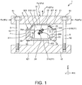
- Fig. 1 is a sectional view showing a force sensor according to the first embodiment.
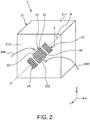
- Fig. 2 is a perspective view of a force detection sensor of the force sensor shown in Fig. 1 .
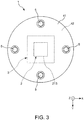
- Fig. 3 is a plan view of the force sensor shown in Fig. 1 .
- the upside in Figs. 1 and 2 and the near side of the paper in Fig. 3 are also referred to as “upper” and the downside in Figs. 1 and 2 and the far side of the paper in Fig. 3 are also referred to as "lower”.
- X-axis three axes orthogonal to one another are referred to as "X-axis", “Y-axis”, and “Z-axis", and directions parallel to the X-axis are also referred to as “X-axis directions”, directions parallel to the Y-axis are also referred to as “Y-axis directions”, and directions parallel to the Z-axis are also referred to as "Z-axis directions”.
- a force sensor 1 shown in Fig. 1 may detect a force Fz (Fz1, Fz2) in the Z-axis directions and a force Fx (Fxl, Fx2) in the X-axis directions.
- the force sensor 1 has a force detection sensor 2, a package 3 housing the force detection sensor 2, a pair of substrates 41, 42 provided to sandwich the package 3 in the thickness direction, and pressurization bolts 5 that couple the substrates 41, 42 and pressurize the force detection sensor 2 via the package 3. As below, these respective parts will be sequentially explained.
- the force detection sensor 2 has a base member 21 including a pressure receiving surface 211 as a first surface subjected to an external force (Fz, Fx) and a placement surface 213 as a second surface having a different normal direction from the pressure receiving surface 211, and electrode fingers 25 placed on the placement surface 213.
- the arrangement direction of the electrode fingers 25 is different from the normal direction of the pressure receiving surface 211 (Z-axis direction). That is, in the plan view of the placement surface 213, the arrangement direction of the electrode fingers 25 tilts with respect to the normal line of the pressure receiving surface 211.
- the force detection sensor 2 forms an SAW resonator that may excite surface acoustic wave in the surface of the base member 21.
- the base member 21 deforms and the pitch of the electrode fingers 25 (intervals between the adjacent electrode fingers 25, i.e., intervals between the electrode fingers 25 in the direction in which surface acoustic wave propagates) changes with the deformation of the base member 21.
- the pitch of the electrode fingers 25 changes, the frequency of the surface acoustic wave (the resonance frequency of the SAW resonator) changes with the change. This is because the frequency of the surface acoustic wave depends on the pitch of the electrode fingers 25.
- the forces Fz, Fz may be detected based on the frequency of the surface acoustic wave excited by the force detection sensor 2.
- the force detection sensor 2 that may exert a higher force detection property is obtained.
- the arrangement direction of the electrode fingers 25 is tilted with respect to the Z-axis, and both the force Fz and the force Fx may be detected. As below, the force detection sensor 2 will be explained in detail.
- the force detection sensor 2 has the base member 21, an inter-digital electrode 22 provided in the base member 21, and a pair of reflectors 23, 24 provided with the inter-digital electrode 22 in between on the placement surface 213.
- the inter-digital electrode 22 is also the comb-like electrode.
- the base member 21 is a quadrangular prism (cubic in the embodiment). Further, the base member 21 has a top surface and a bottom surface, and four side surfaces connecting the top surface and the bottom surface. Of the surfaces, the top surface of the base member 21 is formed by an XY-plane with a normal line along the Z-axis and forms the pressure receiving surface 211 as the first surface subjected to the forces Fz, Fx. Further, one of the four side surfaces is formed by an XZ-plane with a normal line along the Y-axis and forms the placement surface 213 as the second surface on which the inter-digital electrode 22 and the reflectors 23, 24 are placed.
- the placement surface 213 deforms when the pressure receiving surface 211 is subjected to the forces Fz, Fx.
- the placement surface 213 deforms, and thereby, the pitch of the inter-digital electrode 22 changes and the frequency of the surface acoustic wave (the resonance frequency of the SAW resonator) changes according to the change.
- “deformation” here has a broad concept including e.g. the case of not substantial deformation, but with internal distortion (the same applies to the following description).
- the surface adjacent to (i.e., the surface connected to without a different surface in between) the pressure receiving surface 211 is used as the placement surface 213. Accordingly, the forces Fz, Fx applied to the pressure receiving surface 211 are easily transmitted to the placement surface 213. Therefore, the placement surface 213 may be deformed more reliably and more largely. Therefore, the amount of change of the frequency with respect to the magnitude of the applied force may be made larger. As a result, resolution of the force detection sensor 2 is further improved.
- the shape of the base member 21 is not particularly limited as long as the base member has the pressure receiving surface 211 (first surface) and the placement surface 213 (second surface) on which the inter-digital electrode 22 is provided, but may be e.g. a polygonal prism such as a triangular prism, pentagonal prism, hexagonal prism or the like. Further, the respective surfaces of the base member 21 including the pressure receiving surface 211 and the placement surface 213 are not limited to flat surfaces, but entire or part of the surfaces may be curved surfaces.
- the base member 21 is formed by a piezoelectric material. Accordingly, the placement surface 213 includes a surface of the piezoelectric material. Thereby, the surface acoustic wave may be excited more reliably.
- the constituent material of the piezoelectric material is not particularly limited, but includes e.g.
- quartz crystal lithium niobate (LiNbO 3 ), lithium tantalate (LiTaO 3 ), lead zirconate titanate (PZT), lithium tetraborate (Li 2 B 4 O 7 ), langasite (La 3 Ga 5 SiO 14 ), potassium niobate (KNbO 3 ), gallium phosphate (GaPO 4 ), gallium arsenide (GaAs), aluminum nitride (AlN), zinc oxide (ZnO, Zn 2 O 3 ), barium titanate (BaTiO 3 ), lead titanate (PbPO 3 ), potassium sodium niobate ((K,Na)NbO 3 ), bismuth ferrite (BiFeO 3 ), sodium niobate (NaNbO 3 ), bismuth titanate (Bi 4 Ti 3 O 12 ), and sodium bismuth titanate (Na 0.5 Bi 0.5 TiO 3 ).
- the constituent material of the piezoelectric material is quartz crystal. That is, the base member 21 is formed of quartz crystal.
- the force detection sensor 2 may exert higher frequency stability, better frequency-temperature characteristics (the amount of change of the frequency is smaller in a certain temperature range), higher mechanical strength (rigidity, load bearing), higher natural frequency, and higher dynamic range compared to the case using another piezoelectric material. Accordingly, the forces Fz, Fx may be detected in a wider range with higher accuracy. Therefore, the force detection sensor 2 having a better detection property is obtained.
- the pressure receiving surface 211 crosses the electrical axis of the quartz crystal as the piezoelectric material. Specifically, in the embodiment, the pressure receiving surface 211 is orthogonal to the electrical axis of the quartz crystal. That is, the pressure receiving surface 211 is the X-cut face of the quartz crystal.
- the placement surface 213 is parallel to the electrical axis of the quartz crystal.
- the quartz crystal with the cut angle is used, and thereby, surface acoustic wave may be excited more reliably.
- the cut angle of the quartz crystal forming the base member 21 includes e.g. ST cut, CT cut, AT cut, and BT cut, and the ST cut is preferably used.
- the cut angle is used, and thereby, surface acoustic wave called Rayleigh wave may be used and, for example, compared to surface acoustic wave called leaky wave, variations in frequency and frequency-temperature characteristics for the processing accuracy of the base member 21 and the inter-digital electrode 22 may be made smaller. Accordingly, mass productivity is excellent.
- the cut angle of the quartz crystal is not particularly limited as long as surface acoustic wave may be excited.
- the inter-digital electrode 22 is provided in the center part in the Z-axis direction of the placement surface 213 of the base member 21. Further, the inter-digital electrode 22 has a pair of electrodes 221, 222. The pair of electrodes 221, 222 are placed so that their electrode fingers 25 may mesh with each other. That is, the electrodes 221, 222 are placed so that their electrode fingers 25 may be alternately arranged without contact. When a drive voltage is applied between the electrodes 221, 222, cyclical strain is generated between the electrode fingers 25 due to the piezoelectric effect of the base member 21, and surface acoustic wave is excited along the arrangement direction of the electrode fingers 25. Note that, in the embodiment, the extension direction of the electrode fingers 25 and the arrangement direction of the electrode fingers 25 are orthogonal, however, the directions are not necessarily orthogonal as long as surface acoustic wave may be excited.
- the arrangement direction of the electrode fingers 25 of the inter-digital electrode 22 tilts with respect to the normal line (Z-axis) of the pressure receiving surface 211. That is, in the plan view of the placement surface 213, supposing that the axis along the arrangement direction of the electrode fingers 25 of the inter-digital electrode 22 is an axis A, the axis A tilts with respect to the normal line (Z-axis) of the pressure receiving surface 211. Further, the axis A also tilts with respect to the X-axis.
- the tilt angle ⁇ of the axis A with respect to the Z-axis is not particularly limited, but preferably from 30° to 60° and more preferably from 40° to 50°, for example. The angle is set as above, and thereby, even when any one of the forces Fz, Fx is applied, the pitch of the inter-digital electrode 22 may be changed more largely. Therefore, the forces Fz, Fx may be respectively detected with higher sensitivity.
- the pair of reflectors 23, 24 are placed on both sides with the inter-digital electrode 22 in between.
- the reflectors 23, 24 have a function of reflecting the surface acoustic wave propagating in the base member 21 and containing the surface acoustic wave between the reflector 23 and the reflector 24. Note that the reflectors 23, 24 may be omitted.
- the inter-digital electrode 22 and the reflectors 23, 24 may be respectively formed using metal materials having better conductivity including aluminum (Al) and aluminum alloys.
- the aluminum (Al) and the aluminum alloys are materials having smaller specific gravity than other metal materials such as copper (Cu) or tungsten (W), for example, and thus, the influence by the dimension variations of the inter-digital electrode 22 and the reflectors 23, 24 on the frequency-temperature characteristics of the force detection sensor 2 may be suppressed to be smaller.
- the force detection sensor 2 is explained. Note that, in the embodiment, the force detection sensor 2 is the so-called single-port SAW resonator with the single inter-digital electrode 22, however, not limited to that.
- the so-called dual-port SAW resonator with the two inter-digital electrodes 22 provided along the propagation direction of surface acoustic wave may be used. Or, another configuration may be employed.
- the package 3 includes a base 31 having a concave portion 311 opening upward and a cap-shaped lid 32 joined to the upper surface of the base 31 to cover the opening of the concave portion 311. Further, an air-tight housing space S is formed inside of the package 3, and the force detection sensor 2 is housed in the housing space S.
- the atmosphere in the housing space S is not particularly limited, but the space is preferably filled with e.g. a rare gas such as nitrogen, argon, or helium. Thereby, the atmosphere in the housing space S is stable. Further, corrosion of the inter-digital electrode 22 and the reflectors 23, 24 or the like may be suppressed.
- the housing space S may be depressurized (preferably, in vacuum) . Thereby, for example, the viscosity resistance is reduced and the Q-value of the force detection sensor 2 becomes higher, and surface acoustic wave is easily excited.
- the lower surface of the base member 21 is joined to the concave portion 311 (an upper surface of a foundation 31A), and the upper surface of the base member 21 (pressure receiving surface 211) is joined to the lid 32.
- the base 31 and lid 32 and the force detection sensor 2 are joined using e.g. an insulating adhesive. Note that the joining method of the base 31 and lid 32 and the force detection sensor 2 is not particularly limited.
- the force detection sensor 2 and the package 3 are not necessarily joined as long as the force detection sensor 2 may be fixed within the housing space S, for example.
- the lid 32 has a center portion 321 located in the center part and joined to the force detection sensor 2, an outer edge portion 322 located in the outer edge part and joined to the base 31, and a tapered connecting portion 323 located between the center portion 321 and the outer edge portion 322 and connecting the portions.
- the center portion 321 is located on the upside (substrate 41 side) of the outer edge portion 322. Only the center portion 321 is in contact with the substrate 41, and the outer edge portion 322 and the connecting portion 323 are not in contact with (separated from) the substrate 41. Thereby, the forces Fz, Fx may be transmitted to the pressure receiving surface 211 of the force detection sensor 2 more reliably and efficiently.
- the force detection sensor 2 may be pressurized in the Z-axis direction by the package 3 or not. It is preferable that the sensor is not substantially pressurized. Thereby, for example, compared to the case where the sensor is pressurized by the package 3, the rigidity of the package 3 may be lower and the package 3 may be downsized. In the embodiment, the height of the housing space S and the height of the force detection sensor 2 are nearly equal, and, in the state in which the sensor is housed in the package 3, the force detection sensor 2 is not substantially pressurized by the package 3.
- the base 31 has the foundation 31A forming the bottom center part of the base 31 and a frame portion 31B provided around the foundation 31A and forming the outer edge portion and the side wall of the bottom part of the base 31.
- the force detection sensor 2 is mounted on the upper surface of the foundation 31A. That is, the foundation 31A functions as a mount on which the force detection sensor 2 is mounted.
- the frame portion 31B two internal terminals 33 located within the housing space S and two external terminals 34 located on the lower surface of the base 31 and electrically connected to the internal terminals 33 by internal wiring (not shown) are provided.
- the internal terminals 33, 33 are respectively electrically connected to the electrodes 221, 222 of the inter-digital electrode 22 via bonding wires BW.
- the inter-digital electrode 22 may be electrically led to the outside of the package 3, and electrical connection to an external apparatus may be made more easily.
- the constituent material of the frame portion 31B is not particularly limited, but e.g. various ceramics such as aluminum oxide may be used.
- the constituent materials of the foundation 31A and the lid 32 are respectively not particularly limited, but e.g. members having coefficients of linear expansion close to that of the constituent material of the frame portion 31B may be preferably used.
- the constituent materials of the foundation 31A and the lid 32 are metal materials (e.g. alloys including kovar) .
- the foundation 31A and the lid 32 are respectively formed using the metal materials, and thereby, strength and dimension accuracy of the foundation 31A and the lid 32 may be higher, and the sufficient mechanical strength may be exerted and the height of the housing space S may be controlled with higher accuracy. Accordingly, the package 3 may be harder to break and the force detection sensor 2 may be preferably housed in the housing space S.
- the frame portion 31B is formed using the ceramics, and thereby, the strength of the frame portion 31B may be made higher and the whole strength of the package 3 may be increased. Further, the frame portion 31B may be insulated and formation of the internal terminals 33 and the external terminals 34 may be easier.
- the pair of substrates 41, 42 are provided to overlap in the Z-axis direction with the package 3 in between.
- the package 3 is located in the center parts of the substrates 41, 42 in a plan view as seen from the Z-axis direction.
- the substrate 41 is located on the upside of the package 3 and has a plate-like shape.
- the lower surface of the substrate 41 is in contact with the center portion 321 of the lid 32.
- the substrate 42 is located on the downside of the package 3 and has a plate-like base 421 and a projecting portion 422 projecting upward from the base 421.
- the upper surface of the projecting portion 422 is in contact with the lower surface of the base 31.
- the projecting portion 422 is in contact with the lower surface of the foundation 31A of the base 31, but not in contact with the frame portion 31B.
- the constituent materials of the substrates 41, 42 are not particularly limited, but e.g. various metals including iron, nickel, cobalt, gold, platinum, silver, copper, manganese, aluminum, magnesium, zinc, lead, tin, titanium, tungsten, alloys or intermetallic compounds containing at least one kind of the metals, or oxides, nitrides, carbides, etc. of the metals are used.
- the substrates 41, 42 are secured (coupled) using the four pressurization bolts 5.
- the four pressurization bolts 5 are provided at equal intervals (i.e., intervals of 90 degrees) in the outer edge parts of the substrates 41, 42 along the circumferential direction. Further, the respective pressurization bolts 5 are placed so that head portions 51 thereof may be on the substrate 41 side and thread portions 52 of the respective pressurization bolts 5 are screwed into the substrate 42.
- pressure in the Z-axis direction is applied to the force detection sensor 2 within the package 3. That is, the base member 21 is pressurized by the pressurization bolts 5.
- the base member 21 is pressurized, and thereby, for example, compared to the case without pressurization, responsiveness of the force sensor 1 is improved. Further, not only the compression force Fz1 but also the tensile force Fz2 may be detected more accurately.
- the magnitude of pressurization may be adjusted by the amount of tightening of the pressurization bolts 5. Accordingly, adjustment of pressurization is easier.
- the magnitude of pressurization is not particularly limited, but may be appropriately set according to the strength of the force detection sensor 2 or the like. Note that the number and arrangement of the pressurization bolts 5 are not particularly limited as long as the bolts may pressurize the force detection sensor 2. Or, the method is not limited to the method using the pressurization bolts 5 as long as the base member 21 may be pressurized.
- the force sensor 1 may detect the force Fz (Fz1, Fz2) in the Z-axis directions (the directions orthogonal to the pressure receiving surface 211) and the force Fx (Fxl, Fx2) in the X-axis directions (the directions parallel to the pressure receiving surface 211) as described above.
- a force detection method of the force sensor 1 will be explained. Note that, hereinafter, a state in which another external force than pressurization is not substantially applied to the force detection sensor 2 is also referred to as "natural state”. Further, hereinafter, the forces Fz, Fx act on the pressure receiving surface 211 via the substrate 41 with the substrate 42 fixed.
- the base member 21 compressively deforms in the Z-axis direction and the pitch of the inter-digital electrode 22 (the intervals of the adjacent electrode fingers 25, i.e., the intervals between the electrode fingers 25 in the direction in which surface acoustic wave propagates) becomes shorter than that in the natural state. Accordingly, the frequency f of the surface acoustic wave excited in the force detection sensor 2 becomes higher than that in the natural state.
- the base member 21 When the force Fz2 is applied to the pressure receiving surface 211, the base member 21 tensilely deforms in the Z-axis direction and the pitch of the inter-digital electrode 22 becomes longer than that in the natural state. Accordingly, the frequency f of the surface acoustic wave excited in the force detection sensor 2 becomes lower than that in the natural state.
- the force sensor 1 may detect the forces Fz1, Fz2 based on the changes (amounts of change and directions of change) of the frequency f from the natural state.
- the base member 21 shear-deforms toward the positive side in the X-axis direction and the pitch of the inter-digital electrode 22 becomes shorter than that in the natural state. Accordingly, the frequency f of the surface acoustic wave excited in the force detection sensor 2 becomes higher than that in the natural state.
- the base member 21 shear-deforms toward the negative side in the X-axis direction and the pitch of the inter-digital electrode 22 becomes longer than that in the natural state. Accordingly, the frequency f of the surface acoustic wave excited in the force detection sensor 2 becomes lower than that in the natural state.
- the force sensor 1 may detect the forces Fx1, Fx2 based on the changes (amounts of change and directions of change) of the frequency f from the natural state.
- the force Fz and the force Fx may be detected, however, both are detected by the changes in frequency f.
- a device for determination as to whether the applied force is the force Fz or force Fx, a device (circuit or the like) for the determination is necessary and the whole apparatus may be complicated.
- the force sensor 1 it is preferable to use the force sensor 1 in environments in which only one of the force Fz in the Z-axis direction and the force Fx in the X-axis direction is substantially applied. Thereby, the force Fz or force Fx may be accurately detected.
- the force sensor 1 is excellent in convenience because the sensor may be used as both the force sensor that detects the force Fz in the Z-axis direction and the force sensor that detects the force Fx in the X-axis direction.
- the force sensor 1 of the embodiment is explained.
- the force sensor 1 has the force detection sensor 2. Accordingly, the sensor may enjoy the advantages of the above described force detection sensor 2 and exert the excellent reliability and detection property.
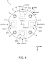
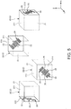
- Fig. 4 is a plan view showing a torque sensor according to the second embodiment.
- Fig. 5 is a perspective view of a force detection sensor of the torque sensor shown in Fig. 4 .
- a torque sensor 10 according to the embodiment is the same as the above described force sensor 1 of the first embodiment mainly except that the number and the placement of the force detection sensors 2 are different.
- the torque sensor 10 of the second embodiment will be described with a focus on the differences from the above described force sensor 1 of the first embodiment and the description of the same items will be omitted. Further, in Figs. 4 and 5 , the same configurations as those of the above described embodiment have the same signs. Furthermore, in Fig. 5 , the bonding wires BW connected to the respective electrodes 221, 222 are not shown.
- the torque sensor 10 shown in Fig. 4 may detect a force Fz (Fz1, Fz2) in the Z-axis directions, a force Fx (Fxl, Fx2) in the X-axis directions, a force Fy (Fy1, Fy2) in the Y-axis directions, and torque ⁇ z ( ⁇ z1, ⁇ z2) about the Z-axis.
- the torque sensor 10 has four packages 3 (3A, 3B, 3C, 3D) housing force detection sensors 2 (2A, 2B, 2C, 2D). Further, the packages 3A, 3B, 3C, 3D are arranged at equal intervals (intervals of 90°) along the outer circumference parts of the substrates 41, 42. The packages 3A, 3B are placed side by side along the Y-axis and the packages 3C, 3D are placed side by side along the X-axis. Note that the configurations of the respective force detection sensors 2 (2A, 2B, 2C, 2D) are the same as those of the above described first embodiment.
- Placement surfaces 213 for the force detection sensors 2A, 2B housed in the packages 3A, 3B are placed with the normal lines along the Y-axis, and placement surfaces 213 for the force detection sensors 2C, 2D housed in the packages 3C, 3D are placed with the normal lines along the X-axis.
- four projecting portions 422 (not shown) of the substrate 42 are provided in correspondence with the respective packages 3A, 3B, 3C, 3D.
- the directions of tilt of the inter-digital electrodes 22 with respect to the Z-axis are opposite to each other in a plan view as seen from one side in the Y-axis direction. Specifically, in the plan view as seen from the positive side in the Y-axis direction, the inter-digital electrode 22 tilts counterclockwise with respect to the Z-axis in the force detection sensor 2A and the inter-digital electrode 22 tilts clockwise with respect to the Z-axis in the force detection sensor 2B.
- the pitch of the inter-digital electrode 22 of one of the force detection sensors 2A, 2B becomes longer than that in the natural state and the pitch of the inter-digital electrode 22 of the other becomes shorter than that in the natural state.
- the directions of tilt of the inter-digital electrodes 22 with respect to the Z-axis are opposite to each other in a plan view as seen from one side in the Y-axis direction. Specifically, in the plan view as seen from the positive side in the X-axis direction, the inter-digital electrode 22 tilts clockwise with respect to the Z-axis in the force detection sensor 2C and the inter-digital electrode 22 tilts counterclockwise with respect to the Z-axis in the force detection sensor 2D.
- the pitch of the inter-digital electrode 22 of one of the force detection sensors 2C, 2D becomes longer than that in the natural state and the pitch of the inter-digital electrode 22 of the other becomes shorter than that in the natural state.
- the torque sensor 10 may detect the force Fz (Fz1, Fz2) in the Z-axis directions, the force Fx (Fxl, Fx2) in the X-axis directions, and the force Fy (Fy1, Fy2) in the Y-axis directions, and may further detect torque ⁇ z ( ⁇ z1, ⁇ z2) about the Z-axis.
- a force detection method of the torque sensor 10 will be explained. Note that, hereinafter, a state in which another external force than pressurization is not substantially applied to the force detection sensors 2 is also referred to as "natural state”. Further, hereinafter, the forces Fz, Fx, Fy, ⁇ z act on the pressure receiving surfaces 211 via the substrate 41 with the substrate 42 fixed.
- the base members 21 of the respective force detection sensors 2A, 2B, 2C, 2D compressively deform in the Z-axis direction.
- the pitches of the inter-digital electrodes 22 of the respective force detection sensors 2A, 2B, 2C, 2D become shorter than those in the natural state.
- frequencies fa, fb, fc, fd of the surface acoustic wave excited in the respective force detection sensors 2A, 2B, 2C, 2D become higher than those in the natural state.
- the base members 21 of the respective force detection sensors 2A, 2B, 2C, 2D tensilely deform in the Z-axis direction.
- the pitches of the inter-digital electrodes 22 of the respective force detection sensors 2A, 2B, 2C, 2D become longer than those in the natural state.
- the frequencies fa, fb, fc, fd of the surface acoustic wave excited in the respective force detection sensors 2A, 2B, 2C, 2D become lower than those in the natural state.
- the torque sensor 10 may detect the forces Fz1, Fz2 based on the changes (amounts of change and directions of change) of the frequencies fa, fb, fc, fd from the natural state.
- the base members 21 of the respective force detection sensors 2A, 2B, 2C, 2D shear-deform toward the positive side in the X-axis direction.
- the pitch of the inter-digital electrode 22 of the force detection sensor 2A becomes shorter than that in the natural state and, on the other hand, the pitch of the inter-digital electrode 22 of the force detection sensor 2B becomes longer than that in the natural state.
- the frequency fa of the surface acoustic wave excited in the force detection sensor 2A becomes higher than that in the natural state
- the frequency fb of the surface acoustic wave excited in the force detection sensor 2B becomes lower than that in the natural state.
- the base members 21 of the respective force detection sensors 2A, 2B, 2C, 2D shear-deform toward the negative side in the X-axis direction.
- the pitch of the inter-digital electrode 22 of the force detection sensor 2A becomes longer than that in the natural state and, on the other hand, the pitch of the inter-digital electrode 22 of the force detection sensor 2B becomes shorter than that in the natural state.
- the frequency fa of the surface acoustic wave excited in the force detection sensor 2A becomes lower than that in the natural state
- the frequency fb of the surface acoustic wave excited in the force detection sensor 2B becomes higher than that in the natural state.
- the torque sensor 10 may detect the forces Fx1, Fx2 based on the changes (amounts of change and directions of change) of the frequencies fa, fb from the natural state.
- the placement surfaces 213 are orthogonal to the directions of the forces Fx1, Fx2. Accordingly, even when the pressure receiving surfaces 211 are subjected to the forces Fx1, Fx2 and the base members 21 deform, the pitches of the inter-digital electrodes 22 do not substantially change (if the pitches change, the pitch changes are sufficiently smaller than the pitch changes of the force detection sensors 2A, 2B) .
- the base members 21 of the respective force detection sensors 2A, 2B, 2C, 2D shear-deform toward the positive side in the Y-axis direction.
- the pitch of the inter-digital electrode 22 of the force detection sensor 2C becomes shorter than that in the natural state and, on the other hand, the pitch of the inter-digital electrode 22 of the force detection sensor 2D becomes longer than that in the natural state.
- the frequency fc of the surface acoustic wave excited in the force detection sensor 2C becomes higher than that in the natural state
- the frequency fd of the surface acoustic wave excited in the force detection sensor 2D becomes lower than that in the natural state.
- the base members 21 of the respective force detection sensors 2A, 2B, 2C, 2D shear-deform toward the negative side in the Y-axis direction.
- the pitch of the inter-digital electrode 22 of the force detection sensor 2C becomes longer than that in the natural state and, on the other hand, the pitch of the inter-digital electrode 22 of the force detection sensor 2D becomes shorter than that in the natural state.
- the frequency fc of the surface acoustic wave excited in the force detection sensor 2C becomes lower than that in the natural state
- the frequency fd of the surface acoustic wave excited in the force detection sensor 2D becomes higher than that in the natural state.
- the torque sensor 10 may detect the forces Fy1, Fy2 based on the changes (amounts of change and directions of change) of the frequencies fc, fd from the natural state.
- the placement surfaces 213 are orthogonal to the directions of the forces Fy1, Fy2. Accordingly, even when the pressure receiving surfaces 211 are subjected to the forces Fy1, Fy2 and the base members 21 deform, the pitches of the inter-digital electrodes 22 do not substantially change (if the pitches change, the pitch changes are sufficiently smaller than the pitch changes of the force detection sensors 2C, 2D) .
- the base members 21 of the respective force detection sensors 2A, 2B, 2C, 2D torsionally deform in the forward direction about the Z-axis (in the clockwise direction as seen from the positive side of the Z-axis).
- the pitches of the inter-digital electrodes 22 of the force detection sensors 2A, 2B become shorter than those in the natural state and, on the other hand, the pitches of the inter-digital electrodes 22 of the force detection sensor 2C, 2D become longer than those in the natural state.
- the frequencies fa, fb of the surface acoustic wave excited in the force detection sensors 2A, 2B become higher than those in the natural state
- the frequencies fc, fd of the surface acoustic wave excited in the force detection sensors 2C, 2D become lower than those in the natural state.
- the base members 21 of the respective force detection sensors 2A, 2B, 2C, 2D torsionally deform in the backward direction about the Z-axis (in the counterclockwise direction as seen from the positive side of the Z-axis).
- the pitches of the inter-digital electrodes 22 of the force detection sensors 2A, 2B become longer than those in the natural state and, on the other hand, the pitches of the inter-digital electrodes 22 of the force detection sensor 2C, 2D become shorter than those in the natural state.
- the frequencies fa, fb of the surface acoustic wave excited in the force detection sensors 2A, 2B become lower than those in the natural state
- the frequencies fc, fd of the surface acoustic wave excited in the force detection sensors 2C, 2D become higher than those in the natural state.
- the torque sensor 10 may detect the torque ⁇ z1, ⁇ z2 based on the changes (amounts of change and directions of change) of the frequencies fa, fb, fc, fd from the natural state.
- Table 1 Frequency Fa fb fc fd Fx1 Higher Lower - - Fx2 Lower Higher - - Fy1 - - Higher Lower Fy2 - - Lower Higher Fz1 Higher Higher Higher Higher Fz2 Lower Lower Lower Lower Lower ⁇ z1 Higher Higher Lower Lower Lower ⁇ z2 Lower Lower Higher Higher Higher
- the torque sensor 10 of the embodiment is explained.
- the torque sensor 10 has the force detection sensors 2. Accordingly, the sensor may enjoy the above described advantages of the force detection sensors 2 and exert excellent reliability and detection property.
- the torque sensor 10 of the embodiment may detect the forces Fz, Fx, Fy in addition to the torque ⁇ z, i.e., is a composite sensor serving as a force sensor and a torque sensor.
- the torque sensor 10 is not limited to that, but may not have the function as a force sensor.
- the torque sensor may detect ⁇ z as a rotation force about the Z-axis, however, may be adapted to further detect a rotation force about the X-axis and a rotation force about the Y-axis by calculation of the frequency changes of the respective force detection sensors 2A, 2B, 2C, 2D as appropriate, for example.
- the torque sensor 10 has the four force detection sensors 2, however, the number of force detection sensors 2 is not particularly limited, but may be e.g. two, three, five or more.
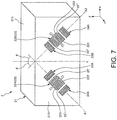
- Fig. 6 is a sectional view showing a force sensor according to the third embodiment.
- Fig. 7 is a perspective view of a force detection sensor of the force sensor shown in Fig. 6 .
- a force sensor 1A according to the embodiment is the same as the above described force sensor 1 of the first embodiment mainly except that the configuration of the force detection sensor is different.
- the force sensor 1A of the third embodiment will be described with a focus on the differences from the above described force sensor 1 of the first embodiment and the description of the same items will be omitted.
- the same configurations as those of the above described embodiments have the same signs.
- the bonding wires BW connected to the respective electrodes 221, 222 are not shown.
- a plurality of inter-digital electrodes 22 are placed on the placement surface 213.
- the sensor has first electrode fingers 25' (first inter-digital electrode 22A) in an arrangement direction tilted toward one side with respect to the normal line (Z-axis) of the pressure receiving surface 211 and second electrode fingers 25" (second inter-digital electrode 22B) in an arrangement direction tilted toward the other side with respect to the normal line (Z-axis) of the pressure receiving surface 211 in the plan view of the placement surface 213.
- the sensor has the first inter-digital electrode 22A tilted toward one side with respect to the normal line (Z-axis) of the pressure receiving surface 211 and the second inter-digital electrode 22B tilted toward the other side with respect to the normal line (Z-axis) of the pressure receiving surface 211 in the plan view of the placement surface 213.
- the force detection sensor 2 contains a plurality of SAW resonators. According to the configuration, both Fz and Fx may be detected by a simple configuration as will be described later. That is, the force sensor 1 (force detection sensor 2) having more detection axes is obtained.
- the number of inter-digital electrodes 22 placed on the placement surface 213 is not particularly limited as long as the number is more than one. In the embodiment, the number is two. Thereby, the number of inter-digital electrodes 22 is smaller and the area of the placement surface 213 may be made smaller by the size of the electrodes. Accordingly, the force detection sensor 2 may be downsized.
- the first inter-digital electrode 22A and the second inter-digital electrode 22B are placed side by side in the X-axis direction.
- the first inter-digital electrode 22A is provided with a tilt clockwise in the drawing with respect to the Z-axis
- the second inter-digital electrode 22B is provided with a tilt counterclockwise in the drawing with respect to the Z-axis.
- the first inter-digital electrode 22A and the second inter-digital electrode 22B are placed in a tapered arrangement such that the separation distance between the electrodes gradually decreases (gradually increases) along the Z-axis direction.
- the first inter-digital electrode 22A and the second inter-digital electrode 22B are provided line-symmetrically with respect to a virtual line L located between the electrodes and parallel to the Z-axis.
- tilt angles ⁇ of the axes A1, A2 with respect to the Z-axis are not particularly limited, but preferably from 10° to 80°, more preferably from 30° to 60°, and even more preferably from 40° to 50°.
- the angles are set as above, and thereby, when any one of the forces Fz, Fx is applied, the pitches of the first and second inter-digital electrodes 22A, 22B may be changed more largely. Therefore, the forces Fz, Fx may be respectively detected with higher sensitivity.
- a pair of reflectors 23A, 24A are provided on both sides with the first inter-digital electrode 22A in between, and a pair of reflectors 23B, 24B are provided on both sides with the second inter-digital electrode 22B in between.
- the force sensor 1A may detect the force Fz (Fz1, Fz2) in the Z-axis directions and the force Fx (Fxl, Fx2) in the X-axis directions .
- a force detection method of the force sensor 1A will be explained. Note that, hereinafter, a state in which another external force than pressurization is not substantially applied to the force detection sensor 2 is also referred to as "natural state”. Further, hereinafter, the forces Fz, Fx, Fy, ⁇ z act on the pressure receiving surface 211 via the substrate 41 with the substrate 42 fixed.
- both of the pitches of the first and second inter-digital electrodes 22A, 22B become shorter than those in the natural state. Accordingly, both of frequencies f1, f2 of surface acoustic wave excited in the first and second inter-digital electrodes 22A, 22B become higher than those in the natural state.
- both of the pitches of the first and second inter-digital electrodes 22A, 22B become longer than those in the natural state. Accordingly, both of frequencies f1, f2 of surface acoustic wave excited in the first and second inter-digital electrodes 22A, 22B become lower than those in the natural state.
- the force sensor 1A may detect the forces Fz1, Fz2 based on the changes (amounts of change and directions of change) of the frequencies f1, f2 from the natural state.
- the base member 21 shear-deforms toward the positive side in the X-axis direction.
- the pitch of the first inter-digital electrode 22A becomes longer than that in the natural state and, on the other hand, the pitch of the second inter-digital electrode 22B becomes shorter than that in the natural state.
- the frequency f1 of the surface acoustic wave excited in the first inter-digital electrode 22A becomes lower than that in the natural state
- the frequency f2 of the surface acoustic wave excited in the second inter-digital electrode 22B becomes higher than that in the natural state.
- the base member 21 shear-deforms toward the negative side in the X-axis direction.
- the pitch of the first inter-digital electrode 22A becomes shorter than that in the natural state and, on the other hand, the pitch of the second inter-digital electrode 22 becomes longer than that in the natural state.
- the frequency f1 of the surface acoustic wave excited in the first inter-digital electrode 22A becomes higher than that in the natural state
- the frequency f2 of the surface acoustic wave excited in the second inter-digital electrode 22B becomes lower than that in the natural state.
- the force sensor 1A may detect the forces Fx1, Fx2 based on the changes (amounts of change and directions of change) of the frequencies f1, f2 from the natural state.
- the force sensor 1A of the embodiment is explained.
- the force sensor 1A has the force detection sensor 2. Accordingly, the sensor may enjoy the above described advantages of the force detection sensor 2 and exert excellent reliability and detection property.
- Fig. 8 is a plan view showing a torque sensor according to the fourth embodiment.
- Fig. 9 is a perspective view of a force detection sensor of the torque sensor shown in Fig. 8 .
- a torque sensor 10A according to the embodiment is the same as the above described force sensor 1A of the third embodiment mainly except that the number and the placement of the force detection sensors 2 are different.
- the torque sensor 10A of the fourth embodiment will be described with a focus on the differences from the above described force sensor 1A of the third embodiment and the description of the same items will be omitted. Further, in Figs. 8 and 9 , the same configurations as those of the above described embodiments have the same signs. Furthermore, in Fig. 9 , the bonding wires BW connected to the respective electrodes 221, 222 are not shown.
- the torque sensor 10A shown in Fig. 8 may detect a force Fz (Fz1, Fz2) in the Z-axis directions, a force Fx (Fxl, Fx2) in the X-axis directions, a force Fy (Fy1, Fy2) in the Y-axis directions, and torque ⁇ z ( ⁇ z1, ⁇ z2) about the Z-axis.
- the torque sensor 10A has four packages 3 (3A, 3B, 3C, 3D) housing force detection sensors 2 (2A, 2B, 2C, 2D). Further, the packages 3A, 3B, 3C, 3D are arranged at equal intervals (intervals of 90°) along the outer circumference parts of the substrates 41, 42. The packages 3A, 3B are placed side by side along the Y-axis and the packages 3C, 3D are placed side by side along the X-axis. Note that the configurations of the respective force detection sensors 2 (2A, 2B, 2C, 2D) are the same as those of the above described third embodiment.
- placement surfaces 213 for the force detection sensors 2A, 2B are placed with normal lines along the Y-axis, and placement surfaces 213 for the force detection sensors 2C, 2D are placed with normal lines along the X-axis.
- the torque sensor 10A may detect the force Fz (Fz1, Fz2) in the Z-axis directions, the force Fx (Fxl, Fx2) in the X-axis directions, and the force Fy (Fy1, Fy2) in the Y-axis directions, and may detect further torque ⁇ z ( ⁇ z1, ⁇ z2) about the Z-axis.
- a force detection method of the torque sensor 10A will be explained. Note that, hereinafter, a state in which another external force than pressurization is not substantially applied to the force detection sensors 2 is also referred to as "natural state”. Further, hereinafter, the forces Fz, Fx, Fy, ⁇ z act on the pressure receiving surfaces 211 via the substrate 41 with the substrate 42 fixed.
- the base members 21 of the respective force detection sensors 2A, 2B, 2C, 2D compressively deform in the Z-axis direction.
- the pitches of the first and second inter-digital electrodes 22A, 22B of the respective force detection sensors 2A, 2B, 2C, 2D become shorter than those in the natural state. Accordingly, both the frequencies f1 of the surface acoustic wave excited by the first inter-digital electrodes 22A and the frequencies f2 of the surface acoustic wave excited by the second inter-digital electrodes 22B in the respective force detection sensors 2A, 2B, 2C, 2D become higher than those in the natural state.
- the base members 21 of the respective force detection sensors 2A, 2B, 2C, 2D tensilely deform in the Z-axis direction.
- the pitches of the first and second inter-digital electrodes 22A, 22B of the respective force detection sensors 2A, 2B, 2C, 2D become longer than those in the natural state. Accordingly, both of the frequencies f1, f2 of the respective force detection sensors 2A, 2B, 2C, 2D become lower than those in the natural state.
- the torque sensor 10A may detect the forces Fz1, Fz2 based on the changes (amounts of change and directions of change) of the frequencies f1, f2 of the respective force detection sensors 2A, 2B, 2C, 2D from the natural state.
- the base members 21 of the respective force detection sensors 2A, 2B, 2C, 2D shear-deform toward the positive side in the X-axis direction.
- the pitch of the first inter-digital electrode 22A of the force detection sensor 2A and the pitch of the second inter-digital electrode 22B of the force detection sensor 2B become shorter than those in the natural state and, on the other hand, the pitches of the second inter-digital electrode 22B of the force detection sensor 2A and the first inter-digital electrode 22A of the force detection sensor 2B become longer than those in the natural state.
- the frequency f1 of the force detection sensor 2A and the frequency f2 of the force detection sensor 2B become higher than those in the natural state, and the frequency f2 of the force detection sensor 2A and the frequency f1 of the force detection sensor 2B become lower than those in the natural state.
- the base members 21 of the respective force detection sensors 2A, 2B, 2C, 2D shear-deform toward the negative side in the X-axis direction.
- the pitch of the second inter-digital electrode 22B of the force detection sensor 2A and the pitch of the first inter-digital electrode 22A of the force detection sensor 2B become shorter than those in the natural state and, on the other hand, the pitches of the first inter-digital electrode 22A of the force detection sensor 2A and the second inter-digital electrode 22B of the force detection sensor 2B become longer than those in the natural state.
- the frequency f2 of the force detection sensor 2A and the frequency f1 of the force detection sensor 2B become higher than those in the natural state, and the frequency f1 of the force detection sensor 2A and the frequency f2 of the force detection sensor 2B become lower than those in the natural state.
- the torque sensor 10A may detect the forces Fx1, Fx2 based on the changes (amounts of change and directions of change) of the frequencies f1, f2 of the force detection sensors 2A, 2B from the natural state.
- the placement surfaces 213 are orthogonal to the directions of the forces Fx1, Fx2. Accordingly, even when the pressure receiving surfaces 211 are subjected to the forces Fx1, Fx2 and the base members 21 deform, the pitches of the first and second inter-digital electrodes 22A, 22B do not substantially change (if the pitches change, the pitch changes are sufficiently smaller than the pitch changes of the force detection sensors 2A, 2B) .
- the base members 21 of the respective force detection sensors 2A, 2B, 2C, 2D shear-deform toward the positive side in the Y-axis direction.
- the pitch of the first inter-digital electrode 22A of the force detection sensor 2C and the pitch of the second inter-digital electrode 22B of the force detection sensor 2D become shorter than those in the natural state and, on the other hand, the pitches of the second inter-digital electrode 22B of the force detection sensor 2C and the first inter-digital electrode 22A of the force detection sensor 2D become longer than those in the natural state.
- the frequency f1 of the force detection sensor 2C and the frequency f2 of the force detection sensor 2D become higher than those in the natural state, and the frequency f2 of the force detection sensor 2C and the frequency f1 of the force detection sensor 2D become lower than those in the natural state.
- the base members 21 of the respective force detection sensors 2A, 2B, 2C, 2D shear-deform toward the negative side in the Y-axis direction.
- the pitch of the second inter-digital electrode 22B of the force detection sensor 2C and the pitch of the first inter-digital electrode 22A of the force detection sensor 2D become shorter than those in the natural state and, on the other hand, the pitches of the first inter-digital electrode 22A of the force detection sensor 2C and the second inter-digital electrode 22B of the force detection sensor 2D become longer than those in the natural state.
- the frequency f2 of the force detection sensor 2C and the frequency f1 of the force detection sensor 2D become higher than those in the natural state, and the frequency f1 of the force detection sensor 2C and the frequency f2 of the force detection sensor 2D become lower than those in the natural state.
- the torque sensor 10A may detect the forces Fy1, Fy2 based on the changes (amounts of change and directions of change) of the frequencies f1, f2 of the force detection sensors 2C, 2D from the natural state.
- the placement surfaces 213 are orthogonal to the directions of the forces Fy1, Fy2. Accordingly, even when the pressure receiving surfaces 211 are subjected to the forces Fy1, Fy2 and the base members 21 deform, the pitches of the first and second inter-digital electrodes 22A, 22B do not substantially change (if the pitches change, the pitch changes are sufficiently smaller than the pitch changes of the force detection sensors 2C, 2D) .
- the base members 21 of the respective force detection sensors 2A, 2B, 2C, 2D torsionally deform in the forward direction about the Z-axis (in the clockwise direction as seen from the positive side of the Z-axis).
- the pitches of the first inter-digital electrodes 22A of the force detection sensors 2A, 2B, 2C, 2D become shorter than those in the natural state and, on the other hand, the pitches of the second inter-digital electrodes 22B of the force detection sensor 2A, 2B, 2C, 2D become longer than those in the natural state.
- the frequencies f1 of the respective force detection sensors 2A, 2B, 2C, 2D become higher than those in the natural state, and the frequencies f2 of the respective force detection sensors 2A, 2B, 2C, 2D become lower than those in the natural state.
- the base members 21 of the respective force detection sensors 2A, 2B, 2C, 2D torsionally deform in the backward direction about the Z-axis (in the counterclockwise direction as seen from the positive side of the Z-axis).
- the pitches of the first inter-digital electrodes 22A of the force detection sensors 2A, 2B, 2C, 2D become longer than those in the natural state and, on the other hand, the pitches of the second inter-digital electrodes 22B of the force detection sensor 2A, 2B, 2C, 2D become shorter than those in the natural state.
- the frequencies f1 of the respective force detection sensors 2A, 2B, 2C, 2D become lower than those in the natural state, and the frequencies f2 of the respective force detection sensors 2A, 2B, 2C, 2D become higher than those in the natural state.
- the torque sensor 10A may detect the torque ⁇ z1, ⁇ z2 based on the changes (amounts of change and directions of change) of the frequencies f1, f2 of the respective force detection sensors 2A, 2B, 2C, 2D from the natural state.
- the torque sensor 10A of the embodiment is explained.
- the torque sensor 10A has the force detection sensors 2. Accordingly, the sensor may enjoy the above described advantages of the force detection sensors 2 and exert excellent reliability and detection property.
- the torque sensor 10A of the embodiment may detect the forces Fz, Fx, Fy in addition to the torque ⁇ z, i.e., is a composite sensor serving as a force sensor and a torque sensor.
- the torque sensor 10A is not limited to that, but may not have the function as a force sensor.
- the torque sensor may detect ⁇ z as a rotation force about the Z-axis, however, may be adapted to further detect a rotation force about the X-axis and a rotation force about the Y-axis by calculation of the frequency changes of the respective force detection sensors 2A, 2B, 2C, 2D as appropriate, for example.
- the torque sensor 10A has the four force detection sensors 2, however, the number of force detection sensors 2 is not particularly limited, but may be e.g. two, three, five or more.
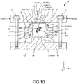
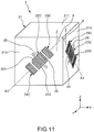
- Fig. 10 is a sectional view showing a force sensor according to the fifth embodiment of the invention.
- Fig. 11 is a perspective view of a force detection sensor of the force sensor shown in Fig. 10 .
- a force sensor 1B according to the embodiment is the same as the above described force sensor 1 of the first embodiment mainly except that the configuration of the force detection sensor is different.
- the force sensor 1B of the fifth embodiment will be described with a focus on the differences from the above described force sensor 1 of the first embodiment and the description of the same items will be omitted.
- the same configurations as those of the above described embodiments have the same signs.
- the bonding wires BW connected to the respective electrodes 221, 222 are not shown.
- the base member 21 has a placement surface 215 as a third surface having a different normal direction from the pressure receiving surface 211 (first surface) and the placement surface 213 (second surface).
- the placement surface 215 is formed by a side surface of the base member 21 and the orientation of the normal line is different from that of the placement surface 213.
- the placement surface 213 is formed by an XZ-plane with the normal line along the Y-axis and the placement surface 215 is formed by a YZ-plane with the normal line along the X-axis. Note that the placement of the placement surface 215 is not particularly limited as long as the orientation is different from that of the placement surface 213.
- the force detection sensor 2 has electrode fingers 25 (inter-digital electrode 22C) placed on the placement surface 213 and electrode fingers 25 (inter-digital electrode 22D) placed on the placement surface 215. Further, in the plan view of the placement surface 213, the arrangement direction of the electrode fingers 25 of the inter-digital electrode 22C placed on the placement surface 213 is different from the normal direction (Z-axis direction) of the pressure receiving surface 211, and, in the plan view of the placement surface 215, the arrangement direction of the electrode fingers 25 of the inter-digital electrode 22D placed on the placement surface 215 is different from the normal direction (Z-axis direction) of the pressure receiving surface 211.
- both the inter-digital electrode 22C and the inter-digital electrode 22D tilt with respect to the normal line of the pressure receiving surface 211.
- the inter-digital electrode 22C tilts clockwise with respect to the Z-axis
- the inter-digital electrode 22D tilts counterclockwise with respect to the Z-axis. Note that the directions of tilt of the inter-digital electrode 22C, 22D are not particularly limited.
- the force Fy in the Y-axis direction may be detected in addition to the force Fz in the Z-axis direction and the force Fx in the X-axis direction. Accordingly, the force sensor 1 (force detection sensor 2) having more detection axes is obtained.
- a tilt angle ⁇ of the axis A3 with respect to the Z-axis is not particularly limited, but preferably from 30° to 60° and more preferably from 40° to 50°, for example.
- a tilt angle ⁇ of the axis A4 with respect to the Z-axis is not particularly limited, but preferably from 30° to 60° and more preferably from 40° to 50°, for example.
- a pair of reflectors 23C, 24C are provided on both sides with the inter-digital electrode 22C in between, and a pair of reflectors 23D, 24D are provided on both sides with the inter-digital electrode 22D in between.
- the base member 21 is formed by a piezoelectric material (quartz crystal). Accordingly, the placement surfaces 213, 215 respectively include surfaces of the piezoelectric material. Thereby, surface acoustic wave may be excited in the placement surfaces 213, 215 more reliably.
- the force sensor 1B may detect the force Fz (Fz1, Fz2) in the Z-axis directions, the force Fx (Fxl, Fx2) in the X-axis directions, and the force Fy (Fy1, Fy2) in the Y-axis directions.
- a force detection method of the force sensor 1B will be explained. Note that, hereinafter, a state in which another external force than pressurization is not substantially applied to the force detection sensor 2 is also referred to as "natural state”. Further, hereinafter, the forces Fz, Fx, Fy, ⁇ z act on the pressure receiving surface 211 via the substrate 41 with the substrate 42 fixed.
- both of the pitches of the inter-digital electrodes 22C, 22D become shorter than those in the natural state. Accordingly, both of frequencies f3, f4 of surface acoustic wave excited in the inter-digital electrodes 22C, 22D become higher than those in the natural state.
- both of the pitches of the inter-digital electrodes 22C, 22D become longer than those in the natural state. Accordingly, both of frequencies f3, f4 of surface acoustic wave excited in the inter-digital electrodes 22C, 22D become lower than those in the natural state.
- the force sensor 1B may detect the forces Fz1, Fz2 based on the changes (amounts of change and directions of change) of the frequencies f3, f4 from the natural state.
- the base member 21 shear-deforms toward the positive side in the X-axis direction. Thereby, the pitch of the inter-digital electrode 22C becomes longer than that in the natural state. Accordingly, the frequency f3 of the surface acoustic wave excited in the inter-digital electrode 22C becomes lower than that in the natural state.
- the base member 21 shear-deforms toward the negative side in the X-axis direction. Thereby, the pitch of the inter-digital electrode 22C becomes shorter than that in the natural state. Accordingly, the frequency f3 of the surface acoustic wave excited in the inter-digital electrode 22C becomes higher than that in the natural state.
- the force sensor 1B may detect the forces Fx1, Fx2 based on the changes (amounts of change and directions of change) of the frequency f3 from the natural state.
- the placement surface 215 is orthogonal to the directions of the forces Fx1, Fx2. Accordingly, even when the pressure receiving surface 211 is subjected to the forces Fx1, Fx2 and the base member 21 deforms, the pitch of the inter-digital electrode 22D does not substantially change (if the pitch changes, the pitch change is sufficiently smaller than the pitch change of the inter-digital electrode 22C). Therefore, even when the forces Fx1, Fx2 are applied, the frequency f4 of the surface acoustic wave excited in the inter-digital electrode 22D changes little from the natural state.
- the base member 21 shear-deforms toward the positive side in the Y-axis direction. Thereby, the pitch of the inter-digital electrode 22D becomes longer than that in the natural state. Accordingly, the frequency f4 of the surface acoustic wave excited in the inter-digital electrode 22D becomes lower than that in the natural state.
- the base member 21 shear-deforms toward the negative side in the Y-axis direction. Thereby, the pitch of the inter-digital electrode 22D becomes shorter than that in the natural state. Accordingly, the frequency f4 of the surface acoustic wave excited in the inter-digital electrode 22D becomes higher than that in the natural state.
- the force sensor 1B may detect the forces Fy1, Fy2 based on the changes (amounts of change and directions of change) of the frequency f4 from the natural state.
- the placement surface 213 is orthogonal to the directions of the forces Fy1, Fy2. Accordingly, even when the pressure receiving surface 211 is subjected to the forces Fy1, Fy2 and the base member 21 deforms, the pitch of the inter-digital electrode 22C does not substantially change (if the pitch changes, the pitch change is sufficiently smaller than the pitch change of the inter-digital electrode 22D). Therefore, even when the forces Fx1, Fx2 are applied, the frequency f3 of the surface acoustic wave excited in the inter-digital electrode 22C changes little from the natural state.
- the force sensor 1B of the embodiment is explained.
- the force sensor 1B has the force detection sensor 2. Accordingly, the sensor may enjoy the above described advantages of the force detection sensor 2 and exert excellent reliability and detection property.
- Fig. 12 is a plan view showing a torque sensor according to the sixth embodiment of the invention.
- Fig. 13 is a perspective view of a force detection sensor of the torque sensor shown in Fig. 12 .
- a torque sensor 10B according to the embodiment is the same as the above described force sensor 1B of the fifth embodiment mainly except that the number and the placement of the force detection sensors 2 are different.
- the torque sensor 10B shown in Fig. 12 may detect a force Fz (Fz1, Fz2) in the Z-axis directions, a force Fx (Fxl, Fx2) in the X-axis directions, a force Fy (Fy1, Fy2) in the Y-axis directions, and torque ⁇ z ( ⁇ z1, ⁇ z2) about the Z-axis.
- the torque sensor 10B has four packages 3 (3A, 3B, 3C, 3D) housing force detection sensors 2 (2A, 2B, 2C, 2D). Further, the packages 3A, 3B, 3C, 3D are arranged at equal intervals (intervals of 90°) along the outer circumference parts of the substrates 41, 42. The packages 3A, 3B are placed side by side along the Y-axis and the packages 3C, 3D are placed side by side along the X-axis. Note that the configurations of the respective force detection sensors 2 (2A, 2B, 2C, 2D) are the same as those of the above described fifth embodiment.
- placement surfaces 213 are XZ-planes with normal lines along the Y-axis
- placement surfaces 215 are YZ-planes with normal lines along the X-axis
- placement surfaces 213 are YZ-planes with normal lines along the X-axis
- placement surfaces 215 are XZ-planes with normal lines along the Y-axis.
- the torque sensor 10B may detect the force Fz (Fz1, Fz2) in the Z-axis directions, the force Fx (Fxl, Fx2) in the X-axis directions, and the force Fy (Fy1, Fy2) in the Y-axis directions, and may further detect torque ⁇ z ( ⁇ z1, ⁇ z2) about the Z-axis.
- a force detection method of the torque sensor 10B will be explained. Note that, hereinafter, a state in which another external force than pressurization is not substantially applied to the force detection sensors 2 is also referred to as "natural state”. Further, hereinafter, the forces Fz, Fx, Fy, ⁇ z act on the pressure receiving surfaces 211 via the substrate 41 with the substrate 42 fixed.
- the base members 21 of the respective force detection sensors 2A, 2B, 2C, 2D compressively deform in the Z-axis direction.
- the pitches of the inter-digital electrodes 22C, 22D of the respective force detection sensors 2A, 2B, 2C, 2D become shorter than those in the natural state.
- both the frequencies f3 of the surface acoustic wave excited by the inter-digital electrodes 22C and the frequencies f4 of the surface acoustic wave excited by the inter-digital electrodes 22D in the respective force detection sensors 2A, 2B, 2C, 2D become higher than those in the natural state.
- the base members 21 of the respective force detection sensors 2A, 2B, 2C, 2D tensilely deform in the Z-axis direction.
- the pitches of the inter-digital electrodes 22C, 22D of the respective force detection sensors 2A, 2B, 2C, 2D become longer than those in the natural state.
- the frequencies f3, f4 of the respective force detection sensors 2A, 2B, 2C, 2D become lower than those in the natural state.
- the torque sensor 10B may detect the forces Fz1, Fz2 based on the changes (amounts of change and directions of change) of the frequencies f3, f4 of the respective force detection sensors 2A, 2B, 2C, 2D from the natural state.
- the base members 21 of the respective force detection sensors 2A, 2B, 2C, 2D shear-deform toward the positive side in the X-axis direction.
- the pitches of the inter-digital electrode 22C of the force detection sensor 2A and the inter-digital electrode 22D of the force detection sensor 2C become shorter than those in the natural state and the pitches of the inter-digital electrode 22C of the force detection sensor 2B and the inter-digital electrode 22D of the force detection sensor 2D become longer than those in the natural state.
- the frequency f3 of the force detection sensor 2A and the frequency f4 of the force detection sensor 2C become higher than those in the natural state
- the frequency f3 of the force detection sensor 2B and the frequency f4 of the force detection sensor 2D become lower than those in the natural state.
- the base members 21 of the respective force detection sensors 2A, 2B, 2C, 2D shear-deform toward the negative side in the X-axis direction.
- the pitches of the inter-digital electrode 22C of the force detection sensor 2A and the inter-digital electrode 22D of the force detection sensor 2C become longer than those in the natural state and the pitches of the inter-digital electrode 22C of the force detection sensor 2B and the inter-digital electrode 22D of the force detection sensor 2D become shorter than those in the natural state.
- the frequency f3 of the force detection sensor 2A and the frequency f4 of the force detection sensor 2C become lower than those in the natural state
- the frequency f3 of the force detection sensor 2B and the frequency f4 of the force detection sensor 2D become higher than those in the natural state.
- the torque sensor 10B may detect the forces Fx1, Fx2 based on the changes (amounts of change and directions of change) of the frequencies f3, f4 of the force detection sensors 2A, 2B, 2C, 2D from the natural state.
- the placement surfaces 215 are orthogonal to the directions of the forces Fx1, Fx2. Accordingly, even when the pressure receiving surfaces 211 are subjected to the forces Fx1, Fx2 and the base members 21 deform, the pitches of the inter-digital electrodes 22D do not substantially change (if the pitches change, the pitch changes are sufficiently smaller than the pitch changes of the inter-digital electrodes 22C) .
- the frequencies f4 of the force detection sensors 2A, 2B change little from the natural state.
- the placement surfaces 213 are orthogonal to the directions of the forces Fx1, Fx2. Accordingly, even when the pressure receiving surfaces 211 are subjected to the forces Fx1, Fx2 and the base members 21 deform, the pitches of the inter-digital electrodes 22C do not substantially change (if the pitches change, the pitch changes are sufficiently smaller than the pitch changes of the inter-digital electrodes 22D). Therefore, even when the forces Fx1, Fx2 are applied, the frequencies f3 of the force detection sensors 2C, 2D change little from the natural state.
- the base members 21 of the respective force detection sensors 2A, 2B, 2C, 2D shear-deform toward the positive side in the Y-axis direction.
- the pitches of the inter-digital electrode 22D of the force detection sensor 2A and the inter-digital electrode 22C of the force detection sensor 2D become shorter than those in the natural state and the pitches of the inter-digital electrode 22D of the force detection sensor 2B and the inter-digital electrode 22C of the force detection sensor 2C become longer than those in the natural state.
- the frequency f4 of the force detection sensor 2A and the frequency f3 of the force detection sensor 2D become higher than those in the natural state
- the frequency f4 of the force detection sensor 2B and the frequency f3 of the force detection sensor 2C become lower than those in the natural state.
- the base members 21 of the respective force detection sensors 2A, 2B, 2C, 2D shear-deform toward the negative side in the Y-axis direction.
- the pitches of the inter-digital electrode 22D of the force detection sensor 2A and the inter-digital electrode 22C of the force detection sensor 2D become longer than those in the natural state and the pitches of the inter-digital electrode 22D of the force detection sensor 2B and the inter-digital electrode 22C of the force detection sensor 2C become shorter than those in the natural state.
- the frequency f4 of the force detection sensor 2A and the frequency f3 of the force detection sensor 2D become lower than those in the natural state
- the frequency f4 of the force detection sensor 2B and the frequency f3 of the force detection sensor 2C become higher than those in the natural state.
- the torque sensor 10B may detect the forces Fy1, Fy2 based on the changes (amounts of change and directions of change) of the frequencies f3, f4 of the force detection sensors 2A, 2B, 2C, 2D from the natural state.
- the placement surfaces 213 are orthogonal to the directions of the forces Fy1, Fy2. Accordingly, even when the pressure receiving surfaces 211 are subjected to the forces Fy1, Fy2 and the base members 21 deform, the pitches of the inter-digital electrodes 22C do not substantially change (if the pitches change, the pitch changes are sufficiently smaller than the pitch changes of the inter-digital electrodes 22D).
- the frequencies f3 of the force detection sensors 2A, 2B change little from the natural state.
- the placement surfaces 215 are orthogonal to the directions of the forces Fy1, Fy2. Accordingly, even when the pressure receiving surfaces 211 are subjected to the forces Fy1, Fy2 and the base members 21 deform, the pitches of the inter-digital electrode 22D do not substantially change (if the pitches change, the pitch changes are sufficiently smaller than the pitch changes of the inter-digital electrodes 22C). Therefore, even when the forces Fy1, Fy2 are applied, the frequencies f4 of the force detection sensors 2C, 2D change little from the natural state.
- the base members 21 of the respective force detection sensors 2A, 2B, 2C, 2D torsionally deform in the forward direction about the Z-axis (in the clockwise direction as seen from the positive side of the Z-axis).
- the pitches of the inter-digital electrodes 22C of the force detection sensors 2A, 2B, 2C, 2D become shorter than those in the natural state and, on the other hand, the pitches of the inter-digital electrodes 22D of the force detection sensor 2A, 2B, 2C, 2D become longer than those in the natural state.
- the frequencies f3 of the force detection sensors 2A, 2B, 2C, 2D become higher than those in the natural state, and the frequencies f4 of the force detection sensors 2A, 2B, 2C, 2D become lower than those in the natural state.
- the base members 21 of the respective force detection sensors 2A, 2B, 2C, 2D torsionally deform in the backward direction about the Z-axis (in the counterclockwise direction as seen from the positive side of the Z-axis).
- the pitches of the inter-digital electrodes 22C of the force detection sensors 2A, 2B, 2C, 2D become longer than those in the natural state and, on the other hand, the pitches of the inter-digital electrodes 22D of the force detection sensor 2A, 2B, 2C, 2D become shorter than those in the natural state.
- the frequencies f3 of the respective force detection sensors 2A, 2B, 2C, 2D become lower than those in the natural state, and the frequencies f4 of the respective force detection sensors 2A, 2B, 2C, 2D become higher than those in the natural state.
- the torque sensor 10B may detect the torque ⁇ z1, ⁇ z2 based on the changes (amounts of change and directions of change) of the frequencies f3, f4 of the respective force detection sensors 2A, 2B, 2C, 2D from the natural state.
- the torque sensor 10B of the embodiment is explained.
- the torque sensor 10B has the force detection sensors 2. Accordingly, the sensor may enjoy the above described advantages of the force detection sensors 2 and exert excellent reliability and detection property.
- the torque sensor 10B of the embodiment may detect the forces Fz, Fx, Fy in addition to the torque ⁇ z, i.e., is a composite sensor serving as a force sensor and a torque sensor.
- the torque sensor 10B is not limited to that, but may not have the function as a force sensor.
- the torque sensor may detect ⁇ z as a rotation force about the Z-axis, however, may be adapted to further detect a rotation force about the X-axis and a rotation force about the Y-axis by calculation of the frequency changes of the respective force detection sensors 2A, 2B, 2C, 2D as appropriate, for example.
- the torque sensor 10B has the four force detection sensors 2, however, the number of force detection sensors 2 is not particularly limited, but may be e.g. two, three, five or more.
- Fig. 14 is a perspective view of a force detection sensor of a force sensor according to the seventh embodiment.
- a force sensor 1C according to the embodiment is the same as the above described force sensor 1 of the first embodiment mainly except that the configuration of the force detection sensor 2 is different.
- the base member 21 has a first base member 21A and a second base member 21B connected to the first base member 21A. Further, the first base member 21A has the pressure receiving surface 211 as the first surface and the second base member 21B has the placement surface 213 as the second surface. That is, the base member has the first base member 21A as a part subjected to the forces Fz, Fx, etc. and pressurization and the second base member 21B with the inter-digital electrode 22 and the reflectors 23, 24 placed thereon as a part that functions as an SAW resonator, and the members are separately formed.
- the base member 21 is formed by the first base member 21A and the second base member 21B, and accordingly, constituent materials of the first base member 21A and the second base member 21B may be respectively appropriately selected. Thereby, the degree of freedom of design of the base member 21 is higher.
- the constituent material of the first base member 21A is not particularly limited, but preferably a relatively hard material.
- the material includes e.g. various metals including iron, nickel, cobalt, gold, platinum, silver, copper, manganese, aluminum, magnesium, zinc, lead, tin, titanium, tungsten, alloys or intermetallic compounds containing at least one kind of the metals, or oxides, nitrides, carbides, etc. of the metals.
- the constituent material of the second base member 21B is not particularly limited as long as the material may excite surface acoustic wave, but various piezoelectric materials cited in the above described first embodiment may be used.
- the second base member 21B is formed using quartz crystal.
- first base member 21A and the second base member 21B are connected (joined) via an adhesive 21C.
- the connecting method of the first base member 21A and the second base member 21B is not particularly limited as long as the force applied to the first base member 21A may be transmitted to the second base member 21B, but may be e.g. concavo-convex fitting, screwing using screws, welding, fusion, soldering, or the like.
- Fig. 15 is a perspective view showing a robot according to the eighth embodiment of the invention.
- a robot 9 shown in Fig. 15 is a robot that may be used in e.g. a manufacturing process that manufactures industrial products such as precision apparatuses.
- the robot 9 has a base 91 fixed to e.g. a floor or ceiling, an arm 92 rotatably coupled to the base 91, an arm 93 rotatably coupled to the arm 92, an arm 94 rotatably coupled to the arm 93, an arm 95 rotatably coupled to the arm 94, an arm 96 rotatably coupled to the arm 95, an arm 97 rotatably coupled to the arm 96, and a robot control unit 98 that controls driving of these arms 92, 93, 94, 95, 96, 97 and an end effector 99.
- a hand connection part is provided in the arm 97 and the end effector 99 according to work to be executed by the robot 9 is attached to the hand connection part.
- a torque sensor 10 including the above described force detection sensor 2 is provided in the robot 9, as a sensor that detects an external force applied to the end effector 99.
- the force detected by the torque sensor 10 is fed back to the robot control unit 98, and thereby, the robot 9 may execute more precise work.
- the robot 9 may sense contact of the end effector 99 with an object for work or an obstacle or the like by the force detected by the torque sensor 10. Accordingly, the operation of grasping and moving the object for work by the end effector 99 or the like may be performed more properly, obstacle avoidance operation, object damage avoidance operation, etc. that have been difficult in the position control of related art may be easily performed, and the robot 9 may execute work more properly and safely.
- the robot 9 has the torque sensor 10 (force detection sensor 2). Accordingly, the robot may enjoy the above described advantages of the force detection sensor 2 and exert excellent reliability and detection property.
- the configuration of the robot 9 is not particularly limited, but the number of arms may be different from that of the embodiment, for example.
- the robot 9 may be the so-called scalar robot or dual-arm robot.
- the robot 9 has the torque sensor 10, however, may have the above described torque sensors 10A, 10B and force sensors 1, 1A, 1B, 1C instead, or may have another configuration.
- the force detection sensor, the force sensor, the torque sensor, and the robot according to the invention are explained with reference to the illustrated embodiments, however, the invention is not limited to those.
- the configurations of the respective parts may be replaced by arbitrary configurations having the same functions. Or, other arbitrary configurations may be added to the invention. Or, the respective embodiments may be combined as appropriate.
- the force detection sensor is not necessarily incorporated in the sensors, but incorporated in another electronic device.
- each of the force sensor and the torque sensor has the package, pair of substrates, and pressurization bolts in addition to the force detection sensor, however, the configurations of the force sensor and the torque sensor are not particularly limited as long as the sensors have the force detection sensor elements.
- the package may be omitted and the force detection sensor element may be directly sandwiched by the pair of substrates .
- the pair of substrates and the pressurization bolts may be omitted. That is, the force detection sensor is not necessarily pressurized.
Landscapes
- Physics & Mathematics (AREA)
- General Physics & Mathematics (AREA)
- Engineering & Computer Science (AREA)
- Acoustics & Sound (AREA)
- Human Computer Interaction (AREA)
- Robotics (AREA)
- Mechanical Engineering (AREA)
- Chemical & Material Sciences (AREA)
- Analytical Chemistry (AREA)
- Force Measurement Appropriate To Specific Purposes (AREA)
- Manipulator (AREA)
Applications Claiming Priority (1)
| Application Number | Priority Date | Filing Date | Title |
|---|---|---|---|
| JP2016228406A JP6862794B2 (ja) | 2016-11-24 | 2016-11-24 | 力検出センサー、力覚センサー、トルクセンサーおよびロボット |
Publications (2)
| Publication Number | Publication Date |
|---|---|
| EP3327416A1 EP3327416A1 (en) | 2018-05-30 |
| EP3327416B1 true EP3327416B1 (en) | 2019-07-31 |
Family
ID=60450485
Family Applications (1)
| Application Number | Title | Priority Date | Filing Date |
|---|---|---|---|
| EP17203041.3A Active EP3327416B1 (en) | 2016-11-24 | 2017-11-22 | Force detection sensor, force sensor, torque sensor, and robot |
Country Status (4)
| Country | Link |
|---|---|
| US (1) | US10682768B2 (ja) |
| EP (1) | EP3327416B1 (ja) |
| JP (1) | JP6862794B2 (ja) |
| CN (1) | CN108106757B (ja) |
Families Citing this family (7)
| Publication number | Priority date | Publication date | Assignee | Title |
|---|---|---|---|---|
| JP6789853B2 (ja) * | 2017-03-08 | 2020-11-25 | 日本電産コパル電子株式会社 | 力覚センサ |
| CN108917668A (zh) * | 2018-06-12 | 2018-11-30 | 重庆大学 | 一种差分式双谐振器声波拉伸应变传感器芯片 |
| JP7127513B2 (ja) * | 2018-11-30 | 2022-08-30 | トヨタ自動車株式会社 | センサシステムおよびロボットハンド |
| CN110274717A (zh) * | 2019-01-17 | 2019-09-24 | 上海肇擎传感技术有限公司 | 一种单轴力矩传感器及其敏感方法 |
| JP7375345B2 (ja) * | 2019-06-27 | 2023-11-08 | セイコーエプソン株式会社 | ロボット |
| US11491663B2 (en) * | 2020-06-16 | 2022-11-08 | Ati Industrial Automation, Inc. | Robotic force/torque sensor with controlled thermal conduction |
| US11796378B1 (en) * | 2021-06-25 | 2023-10-24 | Amazon Technologies, Inc. | Piezoelectric weight sensing apparatus |
Family Cites Families (32)
| Publication number | Priority date | Publication date | Assignee | Title |
|---|---|---|---|---|
| US3878477A (en) * | 1974-01-08 | 1975-04-15 | Hewlett Packard Co | Acoustic surface wave oscillator force-sensing devices |
| US4096740A (en) * | 1974-06-17 | 1978-06-27 | Rockwell International Corporation | Surface acoustic wave strain detector and gage |
| US4107626A (en) * | 1976-12-20 | 1978-08-15 | Gould Inc. | Digital output force sensor using surface acoustic waves |
| JPS57133329A (en) * | 1981-02-12 | 1982-08-18 | Yokogawa Hokushin Electric Corp | Power converter |
| JPS5873821A (ja) * | 1981-10-28 | 1983-05-04 | Yamato Scale Co Ltd | ロ−ドセル式はかり |
| JPS60133320A (ja) * | 1983-12-22 | 1985-07-16 | Ishida Scales Mfg Co Ltd | 荷重検出器 |
| CS267053B1 (en) * | 1985-06-24 | 1990-02-12 | Capek Jan | Palpable sensing element for robot |
| JPH05322670A (ja) | 1992-05-21 | 1993-12-07 | Ishida Co Ltd | 荷重検出器 |
| US5527711A (en) * | 1993-12-13 | 1996-06-18 | Hewlett Packard Company | Method and reagents for binding chemical analytes to a substrate surface, and related analytical devices and diagnostic techniques |
| ATE177530T1 (de) | 1994-08-16 | 1999-03-15 | Siemens Ag | Kraft- oder dehnungssensor |
| WO2001067058A1 (de) * | 2000-03-10 | 2001-09-13 | Siemens Aktiengesellschaft | Verfahren und vorrichtung zur messung eines an einem bauteil wirkenden moments |
| JP2002031574A (ja) | 2000-07-17 | 2002-01-31 | Sharp Corp | 触覚センサ |
| JP2004274696A (ja) * | 2002-10-04 | 2004-09-30 | Seiko Epson Corp | 弾性表面波装置および弾性表面波装置の温度特性調整方法 |
| KR20050099520A (ko) * | 2003-02-05 | 2005-10-13 | 브루넬 유니버시티 | 공진 센서 조립체 |
| JP2005184340A (ja) | 2003-12-18 | 2005-07-07 | Seiko Epson Corp | 弾性表面波チップ |
| JP4826194B2 (ja) | 2005-03-04 | 2011-11-30 | 凸版印刷株式会社 | 弾性表面波素子とその使用方法 |
| GB2426590B (en) | 2005-05-26 | 2009-01-14 | Transense Technologies Plc | Pressure sensor |
| CN101018045A (zh) * | 2006-02-08 | 2007-08-15 | 精工爱普生株式会社 | 弹性表面波元件及电子设备 |
| GB2451861A (en) * | 2007-08-14 | 2009-02-18 | Transense Technologies Plc | Surface acoustic wave based sensor in vented housing |
| JP5310572B2 (ja) | 2010-01-13 | 2013-10-09 | 凸版印刷株式会社 | 圧力センサ |
| US20110221312A1 (en) * | 2010-03-12 | 2011-09-15 | Seiko Epson Corporation | Vibrator element, vibrator, sensor, and electronic apparatus |
| JP5713615B2 (ja) * | 2010-09-17 | 2015-05-07 | 大和製衡株式会社 | ロードセル |
| JP5880935B2 (ja) | 2011-12-20 | 2016-03-09 | セイコーエプソン株式会社 | センサーデバイス、センサーモジュール、ロボット、センサーデバイスの製造方法 |
| JP5895615B2 (ja) * | 2012-03-09 | 2016-03-30 | セイコーエプソン株式会社 | センサーモジュール、力検出装置及びロボット |
| JP6051678B2 (ja) * | 2012-08-22 | 2016-12-27 | セイコーエプソン株式会社 | センサーデバイス、センサーモジュール、力検出装置およびロボット |
| CN103994845B (zh) | 2013-02-19 | 2019-09-10 | 精工爱普生株式会社 | 力检测装置、机械手、以及移动体 |
| JP6102341B2 (ja) | 2013-02-27 | 2017-03-29 | セイコーエプソン株式会社 | 力検出装置、ロボット、電子部品搬送装置、電子部品検査装置、部品加工装置および移動体 |
| JP6163900B2 (ja) * | 2013-06-13 | 2017-07-19 | セイコーエプソン株式会社 | 力検出装置およびロボット |
| US20150013461A1 (en) * | 2013-07-12 | 2015-01-15 | Environetix Technologies Corp. | Device and method for measuring physical parameters using saw sensors |
| JP5459890B1 (ja) * | 2013-09-10 | 2014-04-02 | 株式会社ワコー | 力覚センサ |
| US9705069B2 (en) * | 2013-10-31 | 2017-07-11 | Seiko Epson Corporation | Sensor device, force detecting device, robot, electronic component conveying apparatus, electronic component inspecting apparatus, and component machining apparatus |
| JP6349979B2 (ja) | 2014-06-05 | 2018-07-04 | 株式会社デンソー | 弾性表面波式センサ |
-
2016
- 2016-11-24 JP JP2016228406A patent/JP6862794B2/ja active Active
-
2017
- 2017-10-26 CN CN201711019828.1A patent/CN108106757B/zh active Active
- 2017-11-07 US US15/805,777 patent/US10682768B2/en active Active
- 2017-11-22 EP EP17203041.3A patent/EP3327416B1/en active Active
Non-Patent Citations (1)
| Title |
|---|
| None * |
Also Published As
| Publication number | Publication date |
|---|---|
| US10682768B2 (en) | 2020-06-16 |
| US20180141217A1 (en) | 2018-05-24 |
| EP3327416A1 (en) | 2018-05-30 |
| JP2018084519A (ja) | 2018-05-31 |
| JP6862794B2 (ja) | 2021-04-21 |
| CN108106757A (zh) | 2018-06-01 |
| CN108106757B (zh) | 2022-03-08 |
Similar Documents
| Publication | Publication Date | Title |
|---|---|---|
| EP3327416B1 (en) | Force detection sensor, force sensor, torque sensor, and robot | |
| EP3315932B1 (en) | Force sensor | |
| US10201902B2 (en) | Force detector and robot | |
| US8714013B2 (en) | Acceleration detector, acceleration detecting device, inclination sensor, inclination sensor device, and electronic device | |
| US20140123754A1 (en) | Physical quantity detecting device, electronic apparatus, and moving object | |
| US10520375B2 (en) | Force detection apparatus and robot | |
| US11824521B2 (en) | Vibration substrate having a pair of holding portions and a beam portion connecting the holding portions, vibrator, and vibrator unit | |
| CN109842394A (zh) | 振动器件、振动器件的制造方法、电子设备以及移动体 | |
| JP7314562B2 (ja) | 振動デバイス、発振器、電子機器および移動体 | |
| JP6477843B2 (ja) | 力検出装置、およびロボット | |
| TWI657659B (zh) | 電子裝置、電子機器及移動體 | |
| JP2018087780A (ja) | 力検出装置およびロボット | |
| CN110034743A (zh) | 振动器件、振动器件的制造方法、电子设备以及移动体 | |
| JP5950087B2 (ja) | 物理量検出デバイス、物理量検出器、および電子機器 | |
| WO2021215040A1 (ja) | 圧電振動子 | |
| JP2019114964A (ja) | 振動デバイス、電子機器および移動体 | |
| JP5954531B2 (ja) | 物理量検出デバイス、物理量検出器、および電子機器 | |
| JP2019169796A (ja) | 振動デバイス、電子機器および移動体 | |
| JP2013113786A (ja) | 物理量検出デバイス、物理量検出器、および電子機器 |
Legal Events
| Date | Code | Title | Description |
|---|---|---|---|
| PUAI | Public reference made under article 153(3) epc to a published international application that has entered the european phase |
Free format text: ORIGINAL CODE: 0009012 |
|
| STAA | Information on the status of an ep patent application or granted ep patent |
Free format text: STATUS: THE APPLICATION HAS BEEN PUBLISHED |
|
| AK | Designated contracting states |
Kind code of ref document: A1 Designated state(s): AL AT BE BG CH CY CZ DE DK EE ES FI FR GB GR HR HU IE IS IT LI LT LU LV MC MK MT NL NO PL PT RO RS SE SI SK SM TR |
|
| AX | Request for extension of the european patent |
Extension state: BA ME |
|
| STAA | Information on the status of an ep patent application or granted ep patent |
Free format text: STATUS: REQUEST FOR EXAMINATION WAS MADE |
|
| 17P | Request for examination filed |
Effective date: 20181008 |
|
| RBV | Designated contracting states (corrected) |
Designated state(s): AL AT BE BG CH CY CZ DE DK EE ES FI FR GB GR HR HU IE IS IT LI LT LU LV MC MK MT NL NO PL PT RO RS SE SI SK SM TR |
|
| GRAP | Despatch of communication of intention to grant a patent |
Free format text: ORIGINAL CODE: EPIDOSNIGR1 |
|
| STAA | Information on the status of an ep patent application or granted ep patent |
Free format text: STATUS: GRANT OF PATENT IS INTENDED |
|
| INTG | Intention to grant announced |
Effective date: 20190304 |
|
| GRAS | Grant fee paid |
Free format text: ORIGINAL CODE: EPIDOSNIGR3 |
|
| GRAA | (expected) grant |
Free format text: ORIGINAL CODE: 0009210 |
|
| STAA | Information on the status of an ep patent application or granted ep patent |
Free format text: STATUS: THE PATENT HAS BEEN GRANTED |
|
| AK | Designated contracting states |
Kind code of ref document: B1 Designated state(s): AL AT BE BG CH CY CZ DE DK EE ES FI FR GB GR HR HU IE IS IT LI LT LU LV MC MK MT NL NO PL PT RO RS SE SI SK SM TR |
|
| REG | Reference to a national code |
Ref country code: CH Ref legal event code: EP Ref country code: GB Ref legal event code: FG4D |
|
| REG | Reference to a national code |
Ref country code: AT Ref legal event code: REF Ref document number: 1161411 Country of ref document: AT Kind code of ref document: T Effective date: 20190815 |
|
| REG | Reference to a national code |
Ref country code: IE Ref legal event code: FG4D |
|
| REG | Reference to a national code |
Ref country code: DE Ref legal event code: R096 Ref document number: 602017005712 Country of ref document: DE |
|
| REG | Reference to a national code |
Ref country code: NL Ref legal event code: MP Effective date: 20190731 |
|
| REG | Reference to a national code |
Ref country code: LT Ref legal event code: MG4D |
|
| REG | Reference to a national code |
Ref country code: AT Ref legal event code: MK05 Ref document number: 1161411 Country of ref document: AT Kind code of ref document: T Effective date: 20190731 |
|
| PG25 | Lapsed in a contracting state [announced via postgrant information from national office to epo] |
Ref country code: FI Free format text: LAPSE BECAUSE OF FAILURE TO SUBMIT A TRANSLATION OF THE DESCRIPTION OR TO PAY THE FEE WITHIN THE PRESCRIBED TIME-LIMIT Effective date: 20190731 Ref country code: LT Free format text: LAPSE BECAUSE OF FAILURE TO SUBMIT A TRANSLATION OF THE DESCRIPTION OR TO PAY THE FEE WITHIN THE PRESCRIBED TIME-LIMIT Effective date: 20190731 Ref country code: NL Free format text: LAPSE BECAUSE OF FAILURE TO SUBMIT A TRANSLATION OF THE DESCRIPTION OR TO PAY THE FEE WITHIN THE PRESCRIBED TIME-LIMIT Effective date: 20190731 Ref country code: AT Free format text: LAPSE BECAUSE OF FAILURE TO SUBMIT A TRANSLATION OF THE DESCRIPTION OR TO PAY THE FEE WITHIN THE PRESCRIBED TIME-LIMIT Effective date: 20190731 Ref country code: BG Free format text: LAPSE BECAUSE OF FAILURE TO SUBMIT A TRANSLATION OF THE DESCRIPTION OR TO PAY THE FEE WITHIN THE PRESCRIBED TIME-LIMIT Effective date: 20191031 Ref country code: PT Free format text: LAPSE BECAUSE OF FAILURE TO SUBMIT A TRANSLATION OF THE DESCRIPTION OR TO PAY THE FEE WITHIN THE PRESCRIBED TIME-LIMIT Effective date: 20191202 Ref country code: NO Free format text: LAPSE BECAUSE OF FAILURE TO SUBMIT A TRANSLATION OF THE DESCRIPTION OR TO PAY THE FEE WITHIN THE PRESCRIBED TIME-LIMIT Effective date: 20191031 Ref country code: HR Free format text: LAPSE BECAUSE OF FAILURE TO SUBMIT A TRANSLATION OF THE DESCRIPTION OR TO PAY THE FEE WITHIN THE PRESCRIBED TIME-LIMIT Effective date: 20190731 Ref country code: SE Free format text: LAPSE BECAUSE OF FAILURE TO SUBMIT A TRANSLATION OF THE DESCRIPTION OR TO PAY THE FEE WITHIN THE PRESCRIBED TIME-LIMIT Effective date: 20190731 |
|
| PG25 | Lapsed in a contracting state [announced via postgrant information from national office to epo] |
Ref country code: IS Free format text: LAPSE BECAUSE OF FAILURE TO SUBMIT A TRANSLATION OF THE DESCRIPTION OR TO PAY THE FEE WITHIN THE PRESCRIBED TIME-LIMIT Effective date: 20191130 Ref country code: RS Free format text: LAPSE BECAUSE OF FAILURE TO SUBMIT A TRANSLATION OF THE DESCRIPTION OR TO PAY THE FEE WITHIN THE PRESCRIBED TIME-LIMIT Effective date: 20190731 Ref country code: GR Free format text: LAPSE BECAUSE OF FAILURE TO SUBMIT A TRANSLATION OF THE DESCRIPTION OR TO PAY THE FEE WITHIN THE PRESCRIBED TIME-LIMIT Effective date: 20191101 Ref country code: ES Free format text: LAPSE BECAUSE OF FAILURE TO SUBMIT A TRANSLATION OF THE DESCRIPTION OR TO PAY THE FEE WITHIN THE PRESCRIBED TIME-LIMIT Effective date: 20190731 Ref country code: AL Free format text: LAPSE BECAUSE OF FAILURE TO SUBMIT A TRANSLATION OF THE DESCRIPTION OR TO PAY THE FEE WITHIN THE PRESCRIBED TIME-LIMIT Effective date: 20190731 Ref country code: LV Free format text: LAPSE BECAUSE OF FAILURE TO SUBMIT A TRANSLATION OF THE DESCRIPTION OR TO PAY THE FEE WITHIN THE PRESCRIBED TIME-LIMIT Effective date: 20190731 |
|
| PG25 | Lapsed in a contracting state [announced via postgrant information from national office to epo] |
Ref country code: TR Free format text: LAPSE BECAUSE OF FAILURE TO SUBMIT A TRANSLATION OF THE DESCRIPTION OR TO PAY THE FEE WITHIN THE PRESCRIBED TIME-LIMIT Effective date: 20190731 |
|
| PG25 | Lapsed in a contracting state [announced via postgrant information from national office to epo] |
Ref country code: PL Free format text: LAPSE BECAUSE OF FAILURE TO SUBMIT A TRANSLATION OF THE DESCRIPTION OR TO PAY THE FEE WITHIN THE PRESCRIBED TIME-LIMIT Effective date: 20190731 Ref country code: EE Free format text: LAPSE BECAUSE OF FAILURE TO SUBMIT A TRANSLATION OF THE DESCRIPTION OR TO PAY THE FEE WITHIN THE PRESCRIBED TIME-LIMIT Effective date: 20190731 Ref country code: DK Free format text: LAPSE BECAUSE OF FAILURE TO SUBMIT A TRANSLATION OF THE DESCRIPTION OR TO PAY THE FEE WITHIN THE PRESCRIBED TIME-LIMIT Effective date: 20190731 Ref country code: IT Free format text: LAPSE BECAUSE OF FAILURE TO SUBMIT A TRANSLATION OF THE DESCRIPTION OR TO PAY THE FEE WITHIN THE PRESCRIBED TIME-LIMIT Effective date: 20190731 Ref country code: RO Free format text: LAPSE BECAUSE OF FAILURE TO SUBMIT A TRANSLATION OF THE DESCRIPTION OR TO PAY THE FEE WITHIN THE PRESCRIBED TIME-LIMIT Effective date: 20190731 |
|
| PG25 | Lapsed in a contracting state [announced via postgrant information from national office to epo] |
Ref country code: SK Free format text: LAPSE BECAUSE OF FAILURE TO SUBMIT A TRANSLATION OF THE DESCRIPTION OR TO PAY THE FEE WITHIN THE PRESCRIBED TIME-LIMIT Effective date: 20190731 Ref country code: CZ Free format text: LAPSE BECAUSE OF FAILURE TO SUBMIT A TRANSLATION OF THE DESCRIPTION OR TO PAY THE FEE WITHIN THE PRESCRIBED TIME-LIMIT Effective date: 20190731 Ref country code: IS Free format text: LAPSE BECAUSE OF FAILURE TO SUBMIT A TRANSLATION OF THE DESCRIPTION OR TO PAY THE FEE WITHIN THE PRESCRIBED TIME-LIMIT Effective date: 20200224 Ref country code: SM Free format text: LAPSE BECAUSE OF FAILURE TO SUBMIT A TRANSLATION OF THE DESCRIPTION OR TO PAY THE FEE WITHIN THE PRESCRIBED TIME-LIMIT Effective date: 20190731 |
|
| REG | Reference to a national code |
Ref country code: DE Ref legal event code: R097 Ref document number: 602017005712 Country of ref document: DE |
|
| PLBE | No opposition filed within time limit |
Free format text: ORIGINAL CODE: 0009261 |
|
| STAA | Information on the status of an ep patent application or granted ep patent |
Free format text: STATUS: NO OPPOSITION FILED WITHIN TIME LIMIT |
|
| PG2D | Information on lapse in contracting state deleted |
Ref country code: IS |
|
| PG25 | Lapsed in a contracting state [announced via postgrant information from national office to epo] |
Ref country code: LU Free format text: LAPSE BECAUSE OF NON-PAYMENT OF DUE FEES Effective date: 20191122 Ref country code: MC Free format text: LAPSE BECAUSE OF FAILURE TO SUBMIT A TRANSLATION OF THE DESCRIPTION OR TO PAY THE FEE WITHIN THE PRESCRIBED TIME-LIMIT Effective date: 20190731 Ref country code: IS Free format text: LAPSE BECAUSE OF FAILURE TO SUBMIT A TRANSLATION OF THE DESCRIPTION OR TO PAY THE FEE WITHIN THE PRESCRIBED TIME-LIMIT Effective date: 20191030 |
|
| 26N | No opposition filed |
Effective date: 20200603 |
|
| REG | Reference to a national code |
Ref country code: BE Ref legal event code: MM Effective date: 20191130 |
|
| PG25 | Lapsed in a contracting state [announced via postgrant information from national office to epo] |
Ref country code: SI Free format text: LAPSE BECAUSE OF FAILURE TO SUBMIT A TRANSLATION OF THE DESCRIPTION OR TO PAY THE FEE WITHIN THE PRESCRIBED TIME-LIMIT Effective date: 20190731 |
|
| PG25 | Lapsed in a contracting state [announced via postgrant information from national office to epo] |
Ref country code: IE Free format text: LAPSE BECAUSE OF NON-PAYMENT OF DUE FEES Effective date: 20191122 Ref country code: FR Free format text: LAPSE BECAUSE OF NON-PAYMENT OF DUE FEES Effective date: 20191130 |
|
| PG25 | Lapsed in a contracting state [announced via postgrant information from national office to epo] |
Ref country code: BE Free format text: LAPSE BECAUSE OF NON-PAYMENT OF DUE FEES Effective date: 20191130 |
|
| PG25 | Lapsed in a contracting state [announced via postgrant information from national office to epo] |
Ref country code: CY Free format text: LAPSE BECAUSE OF FAILURE TO SUBMIT A TRANSLATION OF THE DESCRIPTION OR TO PAY THE FEE WITHIN THE PRESCRIBED TIME-LIMIT Effective date: 20190731 |
|
| REG | Reference to a national code |
Ref country code: CH Ref legal event code: PL |
|
| PG25 | Lapsed in a contracting state [announced via postgrant information from national office to epo] |
Ref country code: HU Free format text: LAPSE BECAUSE OF FAILURE TO SUBMIT A TRANSLATION OF THE DESCRIPTION OR TO PAY THE FEE WITHIN THE PRESCRIBED TIME-LIMIT; INVALID AB INITIO Effective date: 20171122 Ref country code: MT Free format text: LAPSE BECAUSE OF FAILURE TO SUBMIT A TRANSLATION OF THE DESCRIPTION OR TO PAY THE FEE WITHIN THE PRESCRIBED TIME-LIMIT Effective date: 20190731 |
|
| PG25 | Lapsed in a contracting state [announced via postgrant information from national office to epo] |
Ref country code: CH Free format text: LAPSE BECAUSE OF NON-PAYMENT OF DUE FEES Effective date: 20201130 Ref country code: LI Free format text: LAPSE BECAUSE OF NON-PAYMENT OF DUE FEES Effective date: 20201130 |
|
| PG25 | Lapsed in a contracting state [announced via postgrant information from national office to epo] |
Ref country code: MK Free format text: LAPSE BECAUSE OF FAILURE TO SUBMIT A TRANSLATION OF THE DESCRIPTION OR TO PAY THE FEE WITHIN THE PRESCRIBED TIME-LIMIT Effective date: 20190731 |
|
| GBPC | Gb: european patent ceased through non-payment of renewal fee |
Effective date: 20211122 |
|
| PG25 | Lapsed in a contracting state [announced via postgrant information from national office to epo] |
Ref country code: GB Free format text: LAPSE BECAUSE OF NON-PAYMENT OF DUE FEES Effective date: 20211122 |
|
| PGFP | Annual fee paid to national office [announced via postgrant information from national office to epo] |
Ref country code: DE Payment date: 20230929 Year of fee payment: 7 |