EP3324542B1 - Adaptiver filter mit verwaltbarer ressourcenteilung - Google Patents
Adaptiver filter mit verwaltbarer ressourcenteilung Download PDFInfo
- Publication number
- EP3324542B1 EP3324542B1 EP16199542.8A EP16199542A EP3324542B1 EP 3324542 B1 EP3324542 B1 EP 3324542B1 EP 16199542 A EP16199542 A EP 16199542A EP 3324542 B1 EP3324542 B1 EP 3324542B1
- Authority
- EP
- European Patent Office
- Prior art keywords
- filter
- tapped delay
- delay signals
- cluster
- filter coefficients
- Prior art date
- Legal status (The legal status is an assumption and is not a legal conclusion. Google has not performed a legal analysis and makes no representation as to the accuracy of the status listed.)
- Active
Links
- 230000003044 adaptive effect Effects 0.000 title claims description 124
- 238000004422 calculation algorithm Methods 0.000 claims description 39
- 238000000034 method Methods 0.000 claims description 38
- 238000011161 development Methods 0.000 claims description 36
- 238000012544 monitoring process Methods 0.000 claims description 22
- 230000004044 response Effects 0.000 claims description 12
- 230000018109 developmental process Effects 0.000 claims 5
- 238000010586 diagram Methods 0.000 description 27
- 238000002347 injection Methods 0.000 description 15
- 239000007924 injection Substances 0.000 description 15
- 238000005070 sampling Methods 0.000 description 14
- 230000008859 change Effects 0.000 description 12
- 230000006870 function Effects 0.000 description 9
- 238000004364 calculation method Methods 0.000 description 8
- 238000013461 design Methods 0.000 description 5
- 230000005055 memory storage Effects 0.000 description 5
- 238000005516 engineering process Methods 0.000 description 3
- 230000003287 optical effect Effects 0.000 description 3
- 230000001174 ascending effect Effects 0.000 description 2
- 230000001419 dependent effect Effects 0.000 description 2
- 239000000835 fiber Substances 0.000 description 2
- 239000002245 particle Substances 0.000 description 2
- 230000000737 periodic effect Effects 0.000 description 2
- 230000006399 behavior Effects 0.000 description 1
- 238000004891 communication Methods 0.000 description 1
- 238000004590 computer program Methods 0.000 description 1
- 238000012937 correction Methods 0.000 description 1
- 230000008878 coupling Effects 0.000 description 1
- 238000010168 coupling process Methods 0.000 description 1
- 238000005859 coupling reaction Methods 0.000 description 1
- 230000003278 mimic effect Effects 0.000 description 1
- 238000012986 modification Methods 0.000 description 1
- 230000004048 modification Effects 0.000 description 1
- 238000005192 partition Methods 0.000 description 1
- 238000012545 processing Methods 0.000 description 1
- 238000000638 solvent extraction Methods 0.000 description 1
- 238000012546 transfer Methods 0.000 description 1
Images


Classifications
-
- H—ELECTRICITY
- H03—ELECTRONIC CIRCUITRY
- H03H—IMPEDANCE NETWORKS, e.g. RESONANT CIRCUITS; RESONATORS
- H03H21/00—Adaptive networks
- H03H21/0012—Digital adaptive filters
- H03H21/0043—Adaptive algorithms
-
- H—ELECTRICITY
- H04—ELECTRIC COMMUNICATION TECHNIQUE
- H04B—TRANSMISSION
- H04B3/00—Line transmission systems
- H04B3/02—Details
- H04B3/20—Reducing echo effects or singing; Opening or closing transmitting path; Conditioning for transmission in one direction or the other
- H04B3/23—Reducing echo effects or singing; Opening or closing transmitting path; Conditioning for transmission in one direction or the other using a replica of transmitted signal in the time domain, e.g. echo cancellers
- H04B3/232—Reducing echo effects or singing; Opening or closing transmitting path; Conditioning for transmission in one direction or the other using a replica of transmitted signal in the time domain, e.g. echo cancellers using phase shift, phase roll or frequency offset correction
-
- G—PHYSICS
- G06—COMPUTING; CALCULATING OR COUNTING
- G06F—ELECTRIC DIGITAL DATA PROCESSING
- G06F9/00—Arrangements for program control, e.g. control units
- G06F9/06—Arrangements for program control, e.g. control units using stored programs, i.e. using an internal store of processing equipment to receive or retain programs
- G06F9/30—Arrangements for executing machine instructions, e.g. instruction decode
- G06F9/38—Concurrent instruction execution, e.g. pipeline, look ahead
- G06F9/3885—Concurrent instruction execution, e.g. pipeline, look ahead using a plurality of independent parallel functional units
- G06F9/3889—Concurrent instruction execution, e.g. pipeline, look ahead using a plurality of independent parallel functional units controlled by multiple instructions, e.g. MIMD, decoupled access or execute
- G06F9/3891—Concurrent instruction execution, e.g. pipeline, look ahead using a plurality of independent parallel functional units controlled by multiple instructions, e.g. MIMD, decoupled access or execute organised in groups of units sharing resources, e.g. clusters
-
- H—ELECTRICITY
- H03—ELECTRONIC CIRCUITRY
- H03H—IMPEDANCE NETWORKS, e.g. RESONANT CIRCUITS; RESONATORS
- H03H21/00—Adaptive networks
- H03H21/0012—Digital adaptive filters
-
- H—ELECTRICITY
- H04—ELECTRIC COMMUNICATION TECHNIQUE
- H04B—TRANSMISSION
- H04B3/00—Line transmission systems
- H04B3/02—Details
- H04B3/20—Reducing echo effects or singing; Opening or closing transmitting path; Conditioning for transmission in one direction or the other
- H04B3/23—Reducing echo effects or singing; Opening or closing transmitting path; Conditioning for transmission in one direction or the other using a replica of transmitted signal in the time domain, e.g. echo cancellers
- H04B3/234—Reducing echo effects or singing; Opening or closing transmitting path; Conditioning for transmission in one direction or the other using a replica of transmitted signal in the time domain, e.g. echo cancellers using double talk detection
-
- H—ELECTRICITY
- H04—ELECTRIC COMMUNICATION TECHNIQUE
- H04B—TRANSMISSION
- H04B3/00—Line transmission systems
- H04B3/02—Details
- H04B3/20—Reducing echo effects or singing; Opening or closing transmitting path; Conditioning for transmission in one direction or the other
- H04B3/23—Reducing echo effects or singing; Opening or closing transmitting path; Conditioning for transmission in one direction or the other using a replica of transmitted signal in the time domain, e.g. echo cancellers
- H04B3/235—Reducing echo effects or singing; Opening or closing transmitting path; Conditioning for transmission in one direction or the other using a replica of transmitted signal in the time domain, e.g. echo cancellers combined with adaptive equaliser
-
- H—ELECTRICITY
- H03—ELECTRONIC CIRCUITRY
- H03H—IMPEDANCE NETWORKS, e.g. RESONANT CIRCUITS; RESONATORS
- H03H21/00—Adaptive networks
- H03H21/0012—Digital adaptive filters
- H03H21/0043—Adaptive algorithms
- H03H2021/0056—Non-recursive least squares algorithm [LMS]
-
- H—ELECTRICITY
- H03—ELECTRONIC CIRCUITRY
- H03H—IMPEDANCE NETWORKS, e.g. RESONANT CIRCUITS; RESONATORS
- H03H21/00—Adaptive networks
- H03H21/0012—Digital adaptive filters
- H03H2021/0085—Applications
- H03H2021/0092—Equalization, i.e. inverse modeling
-
- H—ELECTRICITY
- H03—ELECTRONIC CIRCUITRY
- H03H—IMPEDANCE NETWORKS, e.g. RESONANT CIRCUITS; RESONATORS
- H03H21/00—Adaptive networks
- H03H21/0012—Digital adaptive filters
- H03H2021/0085—Applications
- H03H2021/0094—Interference Cancelling
-
- H—ELECTRICITY
- H03—ELECTRONIC CIRCUITRY
- H03H—IMPEDANCE NETWORKS, e.g. RESONANT CIRCUITS; RESONATORS
- H03H2218/00—Indexing scheme relating to details of digital filters
- H03H2218/08—Resource sharing
Definitions
- the present disclosure relates generally to an adaptive filter.
- the present disclosure relates to an adaptive filter using resource sharing of computational blocks for performing filter coefficient convergence algorithm. More particularly, the present disclosure relates to a manageable sharing of computational block resources for an adaptive filter.
- An adaptive filter is a computational device that attempts to model the relationship between two signals in real time in an iterative manner.
- Such adaptive filters are used in many applications e.g. for canceling undesired signal components.
- Echo cancelers / equalizer for inter-symbol interference cancellation
- Adaptive filters are often realized either as a set of program instructions running on an arithmetical processing device such as a microprocessor or DSP chip, or as a set of logic operations implemented in a field-programmable gate array (FPGA) or in a semicustom or custom VLSI integrated circuit.
- the adaptive filter has a tapped-delay line and a tap-weight coefficient controller for producing a sum of tap signals weighted respectively by tap-weight coefficients.
- a tap-weight coefficient controller for producing a sum of tap signals weighted respectively by tap-weight coefficients.
- the tap-weight (filter) coefficients are updated by correlations between the tap signals and a residual error of a correction signal, which is represented by the sum of the weighted tap signals.
- US 7,120,656 B1 discloses an IR filter apparatus comprising an input responsive to an input signal and an FIR filter that comprises three filter stages.
- a first delay circuit has a first time delay coupled between two of the three filter stages.
- a second delay circuit has a second time delay coupled between another two of the three filter stages. The first time delay and second time delay are different.
- a first memory is connected to the first delay circuit. The first memory is configured to provide a first coefficient corresponding to the first delay.
- a second memory is connected to the second delay circuit. The second memory is configured to provide a second coefficient corresponding to the second delay.
- a shift register is connected to the first memory and the second memory. The first memory is configured to store the first coefficient in response to a value received from the shift register in a first cycle and the second memory is configured to store the second coefficient in response to the value received from the shift register in a second cycle subsequent to the first cycle.
- a preferably optimal use of the computational resources of the adaptive filter for performing the adaptive convergence algorithm is a major desire in view of power efficient implementation for a cost sensitive market.
- the present invention provides an adaptive filter with manageable resource sharing and a method of operating adaptive filter with manageable resource sharing as described in the accompanying claims. Specific embodiments of the invention are set forth in the dependent claims. These and other aspects of the invention will be apparent from and elucidated with reference to the embodiments described hereinafter.
- adaptive filters and in particular techniques of resource sharing are summarized with reference to FIGs. 1 to 6 .
- the illustrated adaptive filters and techniques of resource sharing form the basis of the concept of the present application and are described for the sake of a better and fully understanding of the inventive concept of the present invention.
- FIG. 1 a block diagram of a general adaptive filter is schematically illustrated.
- a digital input signal s(n) is fed into the adaptive filter 100, which is arranged to compute a digital output signal y(n) at each time n.
- the digital output signal y(n) is a function of the digital input signal s(n) and a set of parameters including so-called filter coefficients c i (n).
- the digital output signal y(n) is compared to a response or reference signal d(n) by subtracting the digital output signal y(n) and the reference signal d(n) at each time n.
- the objective of the adaptive convergence algorithm is to minimize a cost function based on the error signal e(n).
- the parameters within the adaptive filter 100 may depend on its design and computational implementation.
- the exemplary adaptive filter 100 comprises a finite number L of filter coefficients co to c L-1 .
- the adaptive filter can take the form of a finite-impulse-response (FIR) filter as exemplified herein with reference to FIG. 2 .
- FIR finite-impulse-response
- a finite-impulse-response (FIR) filter comprises a tapped-delay-line with L-1 delay elements 110.1 to 110.L-1 denoted "Z -1 " module and each filter coefficient is a multiplicative gain.
- the adaptive filter further comprises at least 2L memory locations to store the L tapped delay signals s(n-1) and the L filter coefficients c i (n).
- the adaptive convergence algorithm of an adaptive filter for adjusting the filter coefficients c i (n) is performed to minimize a cost function selected with respect to a respective use case of the adaptive filter.
- ⁇ ( n ) is a vector of states that may be used to describe pertinent information of the characteristics of the input signal, error signal and/or filter coefficients.
- the adaptive filter comprises a coefficient-adjusting module 125, which performs the aforementioned adaptive convergence algorithm. At least the error signal e ( n ) and the input signal vector S ( n ) is input to the coefficient adjusting module 125, which may further comprise at least L memory storage locations to store the filter coefficients c i (n) and to supply the stored filter coefficients c i (n) for generating the output signal y(n). Further parameters required by the adaptive convergence algorithm implemented in the coefficient-adjusting module 125 such as the step size ⁇ ( n ) may be predefined and/or configurable.
- LMS Least mean squares
- C ( n ) [ c 0 ( n ), c 1 ( n ), ⁇ , c L -1 ( n )] T
- S ( n ) [ s ( n ), s ( n - 1), ⁇ , s ( n - L + 1)] T
- ⁇ is the step size and L is the order of the filter.
- the initial values are predefined.
- the filter coefficients would never reach the optimal convergence values in the absolute sense, but a convergence is possible in mean.
- filter coefficients may change by small amounts, they change about the convergence values.
- the value of step-size ⁇ should be chosen properly.
- a filter coefficient changing by small amounts about its optimal convergence value will be referred to as a filter coefficient, which has reached steady state.
- a LMS computational block 120.0 to 120.L-1 may be arranged for each filter coefficient c i (n) of the adaptive filter shown in FIG. 2 .
- Such a LMS computational block 120.0 to 120.L-1 comprises for instance two multipliers, an adder and a memory storage location as illustratively shown in form of a schematic block diagram in FIG. 3 . It should be noted that the computational module of FIG. 3 is merely exemplary and not intended to limit the present application.
- FIG. 4 a block diagram of a further illustrative adaptive filter is schematically illustrated.
- the adaptive filter shown in FIG. 4 makes use of fixed computational resource sharing in order to reduce the implementation complexity and costs.
- the exemplary adaptive filter of FIG. 4 will be explained to introduce to the technique of resource sharing, which is the basis of the concept of the present application.
- the computational resources used for performing the adjustment of the filter coefficients are shared among the filter coefficients c i (n) of the adaptive filter. Only a subset of the filter coefficients c i (n) is adjusted at a current time, e.g. at time n, the remaining subset of filter coefficients c i (n) are maintained and adjusted at a later point in time, e.g. at time n+1.
- n may be understood to designate the sampling index n further described below.
- the exemplary adaptive filter further comprises the LMS computational blocks 120.1, 120.3 and 120.5, wherein each of the LMS computational blocks 120.1, 120.3 and 120.5 is provided for adjusting two different ones of the filter coefficients c i (n).
- the LMS computational block 120.1 is provided and configured to adjust the filter coefficients c 0 (n) and c 1 (n), the LMS computational block 120.3 is provided and configured to adjust the filter coefficients c 2 (n) and c 3 (n) and the LMS computational block 120.5 is provided and configured to adjust the filter coefficients c 4 (n) and c 5 (n).
- Each tapped delay signal s(n-i) and the associated filter coefficient c i (n) is fixedly assigned to one of the computational blocks 120, which is fixedly shared with one or more further tapped delay signals s(n-i) and the associated filter coefficients c i (n).
- Each computational block 120 is timely shared to perform the calculation for adjusting the two or more assigned filter coefficients c i (n) according to the implemented filter coefficient convergence algorithm.
- a LMS computational block such as each LMS computational blocks 120.1, 120.3 and 120.5 may comprises for instance two multipliers, an adder and two memory storage locations, which are selectively coupled to the adder, as illustratively shown in form of a schematic block diagram of FIG. 5 .
- the adjusting procedure of the computational resources sharing exemplary adaptive filter of FIG. 4 is schematically illustrated.
- the computational resources sharing may be implemented with higher values of k, which will be denoted as sharing factor k in the following, wherein k is integer and k > 1.
- the exemplified adaptive filter comprises the three LMS computational blocks 120.1, 120.3 and 120.5.
- the adjusting of filter coefficients in adaptive filter requires computational blocks configured to carry out the adaptive convergence algorithm. Each computational block is enabled to perform the adjusting procedure of one filter coefficient c i (n) at one cycle. Therefore, the number of computational blocks in traditional adaptive filters corresponds to the order L of the adaptive filter or the number of tapped delay signal s(n-i) provided by the tapped-delay-line. In adaptive filters using computational resources sharing, the number of computational blocks is less than the order L of the adaptive filter. Accordingly, only a subset of the filter coefficients is adjusted in one cycle. In an example of the present application, the number of filter coefficients is an integer multiple of the number of filter coefficients in each subset. The integer multiple corresponds to the sharing factor k.
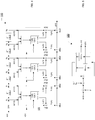
- FIG. 7 a block diagram of a yet another exemplary adaptive filter according to an embodiment of the present application is schematically illustrated.
- the adaptive filter shown in FIG. 7 makes use of manageable computational resource sharing.
- the exemplary adaptive filter comprises a number of computational blocks 260.
- the number of computational blocks 260 is determined at implementation or design stage.
- Each of the computational blocks 260 is enabled to perform the adjusting procedure of a filter coefficient c i (n) at one cycle.
- the adjusting procedure is carried out in accordance with an adaptive convergence algorithm.
- the computational blocks 260 are accordingly configured.
- the computational blocks 260 are not fixedly assigned to one or more tapped delay signals s(n-i).
- a symbol routing logic 300 is provided in the adaptive filter, which is configurable to selectively route any tapped delay signals s(n-i) to any computational block 260.
- each of the computational blocks 260 is freely assignable to one tapped delay signal s(n-1) at one cycle.
- the number w of clusters is configurable.
- the number of computational blocks 260.j comprised in each cluster 250.1 to 250.w may differ.
- the cluster 250.1 comprises a set of C1 computational blocks CB 260.1.1 to 260.1.C1
- the cluster 250.2 comprises a set of C2 computational blocks CB 260.2.1 to 260.2.C2
- the cluster 250.w comprises a set of Cw computational blocks CB 260.w.1 to 260.w.Cw.
- the symbol routing logic 300 routes each one of a number of w sets of tapped delay signals ⁇ s(n-i) ⁇ .1 to ⁇ s(n-i) ⁇ .w to a respective one of the clusters 250.1 to 250.w.
- the number of tapped delay signals s(n-i) comprised by each set may differ.
- a first set ⁇ s(n-i) ⁇ of tapped delay signals s(n-i) is routed to the cluster 250.1 and comprises M1 tapped delay signals s(n-i)
- a second set ⁇ s(n-i) ⁇ of tapped delay signals s(n-i) is routed to the cluster 250.2 and comprises M2 tapped delay signals s(n-i)
- a w-th set ⁇ s(n-i) ⁇ of tapped delay signals s(n-i) is routed to the cluster 250.w and comprises Mw tapped delay signals s(n-i).
- the number of sets of tapped delay signals ⁇ s(n-i) ⁇ .1 to ⁇ s(n-i) ⁇ .w correspond to the number of clusters 250.1 to 250.w.
- the filter coefficients c i (n) are stored in a coefficient memory storage 270, to which the computational blocks 260 have access to read a respective filter coefficient c i (n) from a respective memory location thereof and write an updated filter coefficient c i (n) to the respective memory location thereof.
- the allocation of each computational block 260 to a respective one of the clusters 250.1 to 250.w and the operation of the computational blocks 260 is under control of a cluster controller block 320.
- the cluster controller block 320 is configured to turn on/off the computational blocks 260 individually and/or cluster-wise.
- the cluster controller block 320 is further arranged to configure the computational blocks 260 to enable access to the required filter coefficient c i (n) corresponding to the tapped delay signal s(n-i) supplied thereto by the symbol routing logic 300.
- the routing of the tapped delay signals s(n-1) is under control of a routing controller block 310, which configures the symbol routing logic (300) accordingly.
- the routing controller block 310 is configured to allocate each tapped delay signal s(n-i) to one of the sets of tapped delay signals ⁇ s(n-i) ⁇ .1 to ⁇ s(n-i) ⁇ .w.
- the routing controller block 310 configures the symbol routing logic 300 to route each set of tapped delay signals ⁇ s(n-i) ⁇ .1 to ⁇ s(n-i) ⁇ .w to each respective one of the clusters 250.1 to 250.w.
- Each set of tapped delay signals ⁇ s(n-i) ⁇ .1 to ⁇ s(n-i) ⁇ .w is assigned to one of the clusters 250.1 to 250.w.
- Each cluster 250.1 to 250.w receives the tapped delay signals s(n-i) of one set of tapped delay signals (s(n-i) ⁇ .1 to ⁇ s(n-i) ⁇ .w.
- the routing controller block 310 and the cluster controller block 320 receive information from a monitoring block 200, which has access to the coefficients memory 270 and which is arranged to monitor the development of the filter coefficients c i (n).
- the monitoring block 200 is enabled to supply information relating to the development of the filter coefficients c i (n) to the routing controller block 310 and the cluster controller block 320, which are arranged to dynamically operate the exemplified adaptive filer based on the received information.
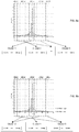
- FIGs. 8a and 8b show exemplary filter coefficient plots.
- the filter coefficients c i (n) comprise more and less dominant coefficients or filter coefficients c i (n) with higher and lower contribution.
- the more dominant filter coefficients are located at the taps around tap number 30 (of 60 taps in total). The remaining filter coefficients may be considered as less dominant. It may be understood that the more dominant filter coefficients may have a lower convergence rate than the less dominant filter coefficient. It may be also understood that a shortened convergence of the more dominate filter coefficients improves the overall operation of the adaptive filter.
- the contribution of the more dominant filter coefficients to the output signal y(n) is more significant than the contribution of the less dominant filter coefficients to the output signal y(n).
- controllable computational resource sharing enables to consider the above considerations in the operation of the adaptive filter while meeting performance requirements at a reduced power consumption.
- the symbol routing logic 300 allows to partition the total number of L tapped delay signals s(n-i) generated on each sampling cycle by the tapped-delay-line into w signal sets of tapped delay signals ⁇ s(n-i) ⁇ .1 to ⁇ s(n-i) ⁇ .w. Each signal set may comprise a different number of tapped delay signals s(n-i).
- the total number of L tapped delay signals s(n-i) may be partitioned into sets based on the monitored, assumed or expected contribution levels to the output signal y(n).
- the total number of L tapped delay signals s(n-i) may be partitioned into sets based on the monitored, assumed or expected value amounts of the associated filter coefficients c i (n).
- a partitioning of the tapped delay signals s(n-i) to signal sets may be predefined, for instance, the tapped delay signals s(n-i) may be evenly assigned to signal sets having substantially the same number of tapped delay signals s(n-i), e.g. when the initial values of the filter coefficients are set to zero.
- the allocation of the tapped delay signals s(n-i) to different signal sets may be based in the initial non-zero values, which may be considered to be indicative of levels of contribution or significance levels of the respective tapped delay signal s(n-i).
- the total number of L tapped delay signals s(n-i) may be repartitioned for instance in response to the monitored value amounts of the filter coefficients c i (n).
- the first signal set 400.1 and the last signal set 400.5 each comprise tapped delay signals s(n-i) with the smallest amount of value of the associated filter coefficients c i (n).
- the third signal set 400.3 comprises tapped delay signals s(n-i) with the highest amount of value of the associated filter coefficients c i (n).
- the second signal set 400.2 and the forth signal set 400.4 each comprise tapped delay signals s(n-i) with the medium amount of value of the associated filter coefficients c i (n).
- Each of the signal sets is associated to one of the clusters, herein five clusters according to the five signal sets.
- the cluster 1 is associated with the third signal set 400.3.
- Computational blocks are allocated to each one of the five clusters.
- the numbers of computational blocks allocated to the clusters may differ.
- the sharing factor k i defines the ratio between the number of tapped delay signals and filter coefficients c i (n), respectively, assigned to a cluster i and the number of computational blocks allocated to the cluster i.
- the sharing factors k i of the different clusters may differ from each other.
- the allocation of tapped delay signal s(n-i) may be performed based on one or more threshold levels applied to the amount values of the filter coefficients c i (n) or the initial values of the filter coefficients c i (n).
- the allocation of the tapped delay signals to different sets values may be based on normalized values of the filter coefficients c i (n). Normalized values of the filter coefficients c i (n) may improve the comparableness.
- the allocation of the tapped delay signals s(n-i) to the five signal sets exemplified in FIG. 8a may be the result of two threshold levels applied to the amount values of the filter coefficients c i (n).
- the amount values or normalized values of the filter coefficients c i (n) may be used for reallocation of the tapped delay signal s(n-i) to the signal sets.
- clusters to which signal sets with less dominant filter coefficients c i (n) are assigned, may be operated with a higher sharing factor than clusters, to which signal sets with more dominant filter coefficients c i (n) are assigned.
- the cluster controller block 320 is arranged to allocate the computational blocks to the clusters. Initially, the computational blocks may be allocated to clusters according to an initial allocation scheme; for instance, the computational blocks may be evenly allocated to clusters comprising substantially the same number of computational blocks. During operation of the adaptive filter, the allocation of the computational blocks may be adapted for instance in response to the monitored contribution levels and/or the state of convergence of the filter coefficients c i (n).
- the tapped delay signal s(n-i) may allocated to three signal sets 400.1, 400.2 and 400.3 based on one two threshold levels (cf. threshold low and threshold high) applied to normalized values of the filter coefficients c i (n).
- a number of N thresholds defines a number of N+1 (sub-) ranges of (normalized) filter coefficient values or value subranges.
- each signal sets may comprise one, two or more subsets of successive tapped delay signals s(n-i).
- the signal sets 400.1 and 400.2 each comprise two continuous subsets of tapped delay signal s(n-i) and the signal set 400.4 comprises one subsets of successive tapped delay signal s(n-i).
- Each of the three signal sets 400.1 to 400.3 is assigned to one of three clusters.
- the number of computational blocks allocated to each of the three cluster may be further selected based on the normalized values of the filter coefficients c i (n) in the respective signal set. In case the normalized values of the filter coefficients c i (n) of a signal set are low in comparison to the other ones, a low number of computational blocks is allocated to the respective cluster, which means that the filter coefficients c i (n) of the signal set with low values are adjusted using a high sharing factor k.
- a high number of computational blocks is allocated to the respective cluster, which means that the filter coefficients c i (n) of the signal set with high values are adjusted using a low sharing factor k.
- a medium number of computational blocks is allocated to the respective cluster, which means that the filter coefficients c i (n) of the signal set with high values are adjusted using a medium sharing factor k.
- the cluster 1 may comprise a high number of computational blocks for adjusting the filter coefficients c i (n) corresponding to the tapped delay signals s(n-i) of the signal set 400.3.
- the cluster 3 may comprise a low number of computational blocks for adjusting the filter coefficients c i (n) corresponding to the tapped delay signals s(n-i) of the signal set 400.1.
- the signal set 400.1 comprises two subsets.
- the cluster 2 may comprise a medium number of computational blocks for adjusting the filter coefficients c i (n) corresponding to the tapped delay signals s(n-i) of the signal set 400.2.
- the signal set 400.2 comprises two subsets.
- the operation of the computational blocks of one or more clusters may be disabled by the cluster controller block 320.
- the cluster controller block 320 is arranged to individually and/or cluster-wise enable or disable the operation of the computational blocks.
- a disabling of the computational blocks of one or more clusters may be performed in response to the monitoring block 200, which is arranged to monitor the development of the filter coefficients c i (n) over time. Based on the monitoring of the development of the filter coefficients c i (n), the monitoring block 200 is enabled to detect when filter coefficients c i (n) have reached the steady state.
- the computational blocks of the cluster can be disabled at least temporarily to reduce the power consumption.
- the computational blocks of the cluster may be disabled for a predefined off-time interval T off , after which the disabled computational blocks are put into operation again.
- the suggested design of the adaptable filter with configurable computational resources sharing enables to flexibly and dynamically assign computational power for a configurable subset of tapped delay signals s(n-i) and filter coefficients c i (n), respectively.
- the available computational power of the computational blocks employed for performing the adjusting procedure according to an adaptive convergence algorithm is efficiently usable while the overall number of implemented computational blocks can be reduced to an economic number.
- the convergence rate of the filter coefficients c i (n) my suffer.
- the convergence time of a filter coefficient c i (n) increases when making use of computational resources sharing.
- the convergence time of a filter c i (n) corresponds to the time period required by the adjusting procedure to yield to a value of the filter coefficient c i (n), which is substantially constant, which changes by small amounts only about its optimum convergence value, or which has reached steady state, in other words.
- FIGs. 10a and 10b schematically illustrate the development of a filter coefficient c i (n) updated over time in accordance with an adaptive convergence algorithm such as the aforementioned LMS algorithm either with or without using resource sharing. Only for the sake of explanation, a substantial linear development of a filter coefficient c i (n) is schematically illustrated. In general, the development of the filter coefficient c i (n) depends on the applied adaptive convergence algorithm.
- the parameter k indicates a factor relating to computational resource sharing.
- the parameter k corresponds to the above-described sharing factor k.
- the slopes of the curve defined by the development of the filter coefficient c i (n) over time are different.
- the slope of the curve determined using computational resource sharing is substantially reduced by the sharing factor k. Accordingly the convergence rate is significantly increased when using computational resource sharing.
- the determined offset is injected to the filter coefficient c i (n) at predefined periods of time.
- the injection of the determined offset is stopped in case the filter coefficient c i (n) varies about the convergence value, which is indicative of the filter coefficient c i (n) having reached the steady state.
- the offset Off i is determined based on a value difference of the filter coefficient c i (n).
- the value difference ⁇ i (n) is further determined each period of time M ⁇ N ⁇ T s after the potential injection of the offset Off i .
- the offset Off i is added to the filter coefficient c i (n) provided that the current slope of the development of the filter coefficient c i (n) is below a predefined threshold.
- a current slope of the development of the filter coefficient c i (n) below the predefined threshold is considered to be indicative of a filter coefficient c i (n) slightly varying about the optimal convergence value.
- the adaptive convergence algorithm is performed for at each cycle, whereas offsets are injected on a periodic basis having a period greater than the iteration cycle of the adaptive convergence algorithm.
- Fig. 10d illustrates a schematic diagram of an exemplary development of the value of a filter coefficient c i (n) over time. Offsets are periodically injected until the value of the filter coefficient c i (n) has substantially (e.g. approximately) reaches its optimal convergence value.
- the diagram of FIG. 10d the development of the value of a filter coefficient c i (n) over time using an adaptive filter with computational resource sharing and offset injection (solid line); the development of the value of a filter coefficient c i (n) over time using an adaptive filter with computational resource sharing without offset injection (dash line); and the development of the value of a filter coefficient c i (n) over time using an adaptive filter without computational resource sharing (dash-dot-dot line).
- the convergence rate of the adaptive filter with computational resource sharing and offset injection substantially corresponds to the convergence rate of the adaptive filter without computational resource sharing.
- the convergence rate of the adaptive filter with computational resource sharing (and without offset injection) is significantly lower.
- FIG. 11a a schematic flow diagram is illustrated showing an exemplary implementation of the method to improve the convergence rate of an adaptive filter with computational resource sharing.
- An example of an adaptive filter with computational resource sharing has been above discussed in more detail.
- the improved convergence rate of a filter coefficient c i (n) is obtained by an offset value Off i (j), which is added or subtracted at a predetermined period of time.
- the adding or subtracting of the offset value Off i (j) depends on a current slope of the development of the filter coefficient c i (n), in particular the adding or subtracting depends on whether the slope is positive (raising filter coefficient) or negative (falling filter coefficient).
- the offset value Off i (j) is based on a periodically determined value difference ⁇ i (j), wherein j is an index to the periods.
- the adaptive convergence algorithm is initialized and values are assigned for a first time period T 1 and a second time period T 2 .
- the sharing factor k is predefined by the implementation of the adaptive filter with computational resources sharing.
- a threshold value TH is assigned, which allows to determine whether or not the filter coefficient c i (n) has reached the steady state.
- the parameter N is greater than the sharing factor k (N > k).
- the second time period T 2 occurs M times in the first time period T 1 .
- the development of the filter coefficient c i (n) is monitored.
- the development is monitored on the basis of the change of the value of the filter coefficient c i (n) developing over time. For instance, a slope is determined from the value of the filter coefficient c i (n), in particular with respect to the second time period T 2 .
- an offset is injected into the iteration of the filter coefficient c i (n).
- such offset is injected each first time period T 1 , only. More particularly, the offset is only injected in case the filter coefficient c i (n) has not reached the steady state, e.g. in case an absolute value of the monitored slope exceeds the predefined threshold TH, which is considered as indicative of the filter coefficient c i (n) still significantly differing from the optimal convergence value.
- the offset to be injected is based on the monitored slope and further on the sharing factor.
- the iteration to calculate the filter coefficient c i (n) is performed.
- the step size ⁇ may be predefined in the initial operation.
- FIG. 11b a schematic flow diagram is illustrated showing an exemplary implementation of the monitoring of the development of the filter coefficient c i (n).
- the filter coefficient c i (n) is monitored based on the development of the value of the filter coefficient c i (n) within the first time period T 1 . For instance, a slope or a value difference is determined at least at the beginning of each first time period T 1 and the ending of each first time period T 1 . The slope or value difference is determined from the change of the values of the filter coefficient c i (n), e.g. over the second time period T 2 .
- a slope or value difference is determined in an operation S220.
- the slope is determined based on the change of the filter coefficient value c i (n) over time / sampling index.
- the slope c i ' is determined based on the values of the filter coefficient c i (n) and filter coefficient c i (n-N) at sampling index n and n-N: c i ′ ⁇ c i n ⁇ c i n ⁇ N N
- the slope c i ' or change ⁇ i may be stored in an operation S240 for later use.
- the stored slope c i * or change ⁇ i * is used for determining the offset.
- FIG. 11c a schematic flow diagram is illustrated showing an exemplary implementation of the injecting of an offset.
- injecting an offset into the iteration of the filter coefficient c i (n) is performed provided that the filter coefficient c i (n) has not reached steady state.
- the offset Off is determined in an operation S320.
- the offset Off is based on the stored slope c i * or change ⁇ i * to consider the development of the filter coefficient c i (n) over the first time period T 1 .
- the offset Off is injected into the iteration of the filter coefficient c i (n) if the filter coefficient c i (n) has not reached steady state.
- the current slope c i ' or the current value difference ⁇ i is compared against the predefined threshold TH.
- the current slope c i ' is for instance determined from a difference quotient based on the filter coefficient c i (n) at different points in time, e.g. points in time n and (n-N).
- the current value difference ⁇ i is for instance determined from a value difference based on the filter coefficient c i (n) at different points in time, e.g. points in time n and (n-N).
- the current slope c i ' is the slope determined by the previous operation relating to the monitoring of the filter coefficient c i (n).
- the current value difference ⁇ i is the value difference determined by the previous operation relating to the monitoring of the filter coefficient c i (n). c i ′ ⁇ TH c ; or ⁇ i ⁇ TH ⁇ wherein TH ⁇ ⁇ TH C ⁇ N in the present example.
- FIG. 11d a schematic flow diagram is illustrated showing a further exemplary implementation of the injecting of an offset.
- an operation S310 it is determined whether or not the first time period T 1 has lapsed. If the first time period T 1 has lapsed, the offset Off is determined in an operation S320.
- the current slope c i ' or the current change ⁇ i is compared against the predefined threshold TH (TH c and TH ⁇ , respectively).
- the offset Off is injected into the iteration calculation of the filter coefficient c i (n).
- the operations S310 to S330 correspond to the respective operations described above with reference to FIG. 11c . An unnecessary repetition is omitted.
- an operation S340 it is determined whether the development of the filter coefficient c i (n) over time shows an ascending or descending behavior. Whether the filter coefficient c i (n) ascends or descends over time can be determined from the current slope c i ' or the current value difference ⁇ i .
- the filter coefficient c i (n) ascends over time, otherwise if the current slope c i '(n) or the current change ⁇ i is less than 0, the filter coefficient c i (n) descends over time: c i ′ , ⁇ i > 0 : ascending or c i ′ , ⁇ i ⁇ 0 : descending .
- FIG. 12 a block diagram of another exemplary adaptive filter according to an embodiment of the present application is schematically illustrated.
- the adaptive filter shown in FIG. 12 has a filter order L and makes use of computational resource sharing in order to reduce the implementation complexity and costs.
- the LMS computational block 120.1 is for instance used to adjust the filter coefficients c 0 (n) to c 2 (n) and the LMS computational block 120.L/k is for instance used to adjust the filter coefficients c L-3 (n) to c L-1 (n) Those skilled in the art will understand that the computational resources sharing exemplary adaptive filter of FIG. 12 is only one illustrative example of a computational resources sharing adaptive filter and the present application is not intended to be limited thereto.
- the adaptive filter further comprises at least L memory locations to store the L filter coefficients c i (n).
- the adaptive filter further comprises a monitoring block 200, which has access to the filter coefficients c i (n) and which is arranged to monitor the development of the filter coefficients c i (n).
- the monitoring block 200 is configured to carry out the method of monitoring in particular as described above with reference to the flow diagrams shown in FIGs. 11a and 11b .
- the adaptive filter further comprises a offset calculation block 210, which receives information from the monitoring block 200 about the development of the values of the filter coefficients c i (n) and is arranged to compute offsets values Off i for the filter coefficients c i (n) on a periodic time scale and inject the computed offsets Off i into the adjusting procedure of the filter coefficients c i (n).
- the offset computation block 210 is configured to carry out the method of monitoring in particular as described above with reference to the flow diagrams shown in FIGs. 11a , 11c and 11d .
- the offset injection should not be understood to be limited to the LMS (least mean square) algorithm for adjusting the filter coefficient, with regard to which the methodology to improve the convergence rate has been illustratively explained above.
- the LMS algorithm is but one of an entire family of algorithms, which are based on approximations to steepest descent procedures.
- the family of algorithms further comprises for instance the sign-error algorithm, the sign-delta algorithm, sign-sign algorithm, zero-forcing algorithm and power-to-two quantized algorithm.
- the steepest descent procedures are based on the mean-squared error (MSE) cost function, which has been shown as useful for adaptive FIR filters.
- MSE mean-squared error
- further algorithm are known, which are based on non-MSE criteria.
- C n C n + Off ⁇ n
- C n + 1 C n + ⁇ n ⁇ G e n , S n , ⁇ n
- the technique of offset injection has been described above with reference to an adaptive filter with fixed resource sharing, it is immediately understood by those skilled in the art for this disclosure that aforementioned offset injection technique is likewise applicable with the adaptive filter with configurable computational resources sharing described with reference to FIGs. 7 to 9 .
- the offset to be injected is hence determined on the basis of the development of the individual filter coefficient c i (n) and the sharing factor k j of the one cluster 250.j, at which the convergence procedure for the individual filter coefficient c i (n) is performed.
- the offset calculation block 210 may be arranged with the monitoring block 200 and the filter coefficient memory 270.
- the monitoring block 200 further is configured as described above to enable the offset calculation block 210 to determine offsets Off i for the filter coefficient c i (n).
- the calculated offsets Off i may be periodically injected the adaptive convergence algorithm via access to the filter coefficient memory 270.
- the sharing factor k j may be determined from information supplied by the routing controller block 310 and the cluster controller block 320. The information is for instance indicative of the number of tapped delay signals in each of the signal sets ⁇ (s(n-i) ⁇ and the number of computational blocks 260 in each cluster 250.1 to 250.w, respectively.
- DSP digital signal processor
- ASIC application specific integrated circuit
- FPGA field programmable gate array
- a general-purpose processor may be a microprocessor, but in the alternative, the processor may be any conventional processor, controller, microcontroller, or state machine.
- a processor may also be implemented as a combination of computing devices, e.g., a combination of a DSP and a microprocessor, a plurality of microprocessors, one or more microprocessors in conjunction with a DSP core, or any other such configuration.
- a software module may reside in RAM memory, flash memory, ROM memory, EPROM memory, EEPROM memory, registers, hard disk, a removable disk, a CD-ROM, or any other form of storage medium known in the art.
- An exemplary storage medium is coupled to the processor such that the processor can read information from, and write information to, the storage medium.
- the storage medium may be integral to the processor.
- the processor and the storage medium may reside in an ASIC.
- the ASIC may reside in a user terminal.
- the processor and the storage medium may reside as discrete components in a user terminal.
- the functions described may be implemented in hardware, software, firmware, or any combination thereof. If implemented in software, the functions may be stored on or transmitted over as one or more instructions or code on a computer-readable medium.
- Computer-readable media includes both computer storage media and communication media including any medium that facilitates transfer of a computer program from one place to another.
- a storage media may be any available media that can be accessed by a general purpose or special purpose computer.
- such computer-readable media can comprise RAM, ROM, EEPROM, CD-ROM or other optical disk storage, magnetic disk storage or other magnetic storage devices, or any other medium that can be used to carry or store desired program code means in the form of instructions or data structures and that can be accessed by a general-purpose or special-purpose computer, or a general-purpose or special-purpose processor. Also, any connection is properly termed a computer-readable medium.
- Disk and disc includes compact disc (CD), laser disc, optical disc, digital versatile disc (DVD), floppy disk and Blu-ray disc where disks usually reproduce data magnetically, while discs reproduce data optically with lasers. Combinations of the above should also be included within the scope of computer-readable media.
Claims (15)
- Ein adaptiver Filter unter Verwenden von Ressourcen Sharing,
wobei der adaptive Filter (100) aufweist:
eine angezapfte Verzögerungsleitung (110, 110.1 bis 110.L-1), welche bereitstellt L angezapfte Verzögerungssignale, s(n-i),
wobei L eine Filterordnung ist von dem adaptiven Filter;
eine Anzahl von rechnergestützten Blöcken (260; 260.1 bis 260.1.C1; 260.2 bis 260.2.C2; und 260.w.1 bis 260.w.Cw), welche jeweils konfiguriert sind zum Einstellen eines Filterkoeffizienten, ci(n), in einem Zyklus von einem wiederholenden Vorgang gemäß einem adaptiven Konvergenzalgorithmus,
wobei die Anzahl von rechnergestützten Blöcken (260) geringer ist als die Filterordnung L; der adaptive Filter ist dadurch gekennzeichnet, dass dieser ferner aufweist:
einen Cluster Kontroller (320), welcher konfiguriert ist zum Zuordnen von jedem von den rechnergestützten Blöcken (260) zu einem von einer Anzahl von w Clustern (250, 250.1 bis 250.w),
wobei w eine positive Ganzzahl ist; und
eine Symbol Routing Logik (300), welche eingerichtet ist zum
Zuordnen der angezapften Verzögerungssignale, s(n-i), zu einer Anzahl von w Sätzen, {s(n-i)},
wobei die Anzahl von w Clustern (250) korrespondiert zu der Anzahl von w Sätzen von den angezapften Verzögerungssignalen, {s(n-i)}, und
Routen von jedem einen von den Sätzen von angezapften Verzögerungssignalen, {s(n-i)}, zu einem respektiven einen von den Clustern (250),
wobei die rechnergestützten Blöcke (260) von jedem Cluster (250) bereitgestellt sind zum Einstellen der Filterkoeffizienten, ci(n), welche assoziiert sid mit dem Satz von angezapften Verzögerungssignalen, {s(n-i)}, die geroutet sind zu dem respektiven einen von den Clustern (250),
wobei die rechnergestützten Blöcke (260) von jedem Cluster (250) zeitlich geteilt werden unter den Filterkoeffizienten, ci(n), von einem Satz von den angezapften Verzögerungssignalen, {s(n-i)}; und
einen Routing Kontroller (310), welcher bereitgestellt ist zum Konfigurieren des Routing von den angezapften Verzögerungssignalen, s(n-i), zu dem respektiven Cluster (250) in Übereinstimmung mit der Zuordnung davon. - Der adaptive Filter gemäß Anspruch 1, ferner aufweisend:
einen Überwachungsblock (200), welcher konfiguriert ist zum Überwachen von Entwicklungen von den Filterkoeffizienten, ci(n), über Zeit. - Der adaptive Filter gemäß Anspruch 1 bis Anspruch 2,
wobei der Cluster Kontroller (320) konfiguriert ist zum dynamischen Umverteilen der rechnergestützten Blöcke (260) zu einem respektiven einen von den Clustern (250). - Der adaptive Filter gemäß Anspruch 3,
wobei der Cluster Kontroller (320) konfiguriert ist zum Umverteilen der rechnergestützten Blöcke zu einem von den Clustern (250) als Antwort auf Information bezogen auf die Entwicklungen von den Filterkoeffizienten, ci(n), generiert mittels des Routing Kontrollers (310). - Der adaptive Filter gemäß irgendeinem der Ansprüche 1 bis 4,
wobei der Cluster Kontroller (320) konfiguriert ist zum Unterdrücken von einem oder mehreren von den rechnergestützten Blöcken (260) als Antwort auf Information bezogen auf die Entwicklungen von den Filterkoeffizienten, ci(n), generiert mittels des Routing Kontrollers (310). - Der adaptive Filter gemäß irgendeinem der Ansprüche 1 bis 5,
wobei der Cluster Kontroller (320) konfiguriert ist zum selektiven Unterdrücken der rechnergestützten Blöcke (260), welche zugeordnet sind zu einem von den Clustern (250), als Antwort auf Information bezogen auf die Entwicklungen von den Filterkoeffizienten, ci(n), generiert mittels des Routing Kontrollers (310). - Der adaptive Filter gemäß irgendeinem der Ansprüche 1 bis 6,
wobei der Routing Kontroller (310) eingerichtet ist zum dynamischen Routen von jedem einen von den angezapften Verzögerungssignalen, s(n-i), zu einem von den Clustern (250). - Der adaptive Filter gemäß irgendeinem der Ansprüche 1 bis 7,
wobei jeder Satz von den angezapften Verzögerungssignalen, {s(n-i)}, aufweist einen oder mehrere Untersätze von sukzessiv angezapften Verzögerungssignalen, {s(n-i)},
wobei i = i1,..., i2,
wobei i1 und i2 positive Ganzzahlen sind, i2 > i1. - Der adaptive Filter gemäß irgendeinem der Ansprüche 1 bis 8,
wobei der Überwachungsblock (200) konfiguriert ist zum Detektieren, ob oder ob nicht ein Filterkoeffizient, ci(n), erreicht hat einen dauerhaften Zustand;
wobei der Cluster Kontroller (320) konfiguriert ist zum Unterdrücken der rechnergestützten Blöcke (260), welche zugeordnet sind zu einem von den Clustern (250), als Antwort auf den Überwachungsblock (200), der detektiert, dass die Filterkoeffizienten, ci(n), welche assoziiert sind mit dem Satz von angezapften Verzögerungssignalen, {s(n-i)}, die geroutet sind zu dem einen Cluster (250), den dauerhaften Status erreicht haben. - Der adaptive Filter gemäß irgendeinem der Ansprüche 1 bis 9,
wobei der Cluster Kontroller (320) konfiguriert ist zum Unterdrücken der rechnergestützten Blöcke (260) von zumindest einem von den Clustern (250) für eine vordefinierte Ruhezeit Periode, Toff. - Der adaptive Filter gemäß irgendeinem der Ansprüche 1 bis 10,
wobei jeder Cluster (250.j) einen individuellen Teilungsfaktor, kj, hat, welcher definiert ist durch ein Verhältnis von der Anzahl Mj von den angezapften Verzögerungssignalen, s(n-i), in einem von den Sätzen von angezapften Signalen, {s(n-i)}, und der Anzahl Cj von rechnergestützten Blöcken (260.j.1 bis 260.j.Cj) von dem respektiven einen von den Clustern (250.w),
wobei kj = Mj / Cj und j = 1, ..., w. - Der adaptive Filter gemäß irgendeinem der Ansprüche 1 bis 11,
wobei der Überwachungsblock (200) konfiguriert ist zu Detektieren von Beteiligungslevel von den Filterkoeffizienten, ci(n),
wobei mehr dominante Filterkoeffizienten, ci(n), ein höheres Level von Beteiligung haben zu einem Ausgangssignal, y(n), von dem adaptiven Filter als weniger dominante Filterkoeffizienten, ci(n),
wobei der Cluster Kontroller (320) konfiguriert ist zum Zuordnen der Anzahl von w rechnergestützten Blöcken (260) zu den Clustern (250) abhängig von den detektierten Beteiligungsleveln von den Filterkoeffizienten, ci(n),
wobei der Routing Kontroller (310) konfiguriert ist zum individuellen Zuordnen einer Anzahl von angezapften Verzögerungssignalen, s(n-i), in jedem Satz von angezapften Verzögerungssignalen, {s(n-i)}, die geroutet sind durch die Symbol Routing Logik (300) zu dem respektiven Cluster (250) abhängig von dem detektierten Beteiligungsleveln von den Filterkoeffizienten, ci(n), welche assoziiert sind mit dem respektiven Satz von angezapften Verzögerungssignalen, {s(n-i)}. - Ein Verfahren zum Betreiben eines adaptiven Filters unter Verwenden von Ressourcen Sharing,
wobei der adaptive Filter (100) aufweist
eine angezapfte Verzögerungsleitung (110, 110.1 bis 110.L-1), welche bereitstellt L angezapfte Verzögerungssignale, s(n-i),
wobei L eine Filterordnung von dem adaptiven Filter ist; und
eine Anzahl von rechnergestützten Blöcken (260; 260.1 bis 260.1.C1, 260.2 bis 260.2.C2; und 260.w bist 260.w.Cw), welche jeweils konfiguriert sind zum Einstellen einen Filterkoeffizienten, ci(n), in einem Zyklus von einem wiederholenden Vorgang gemäß einem adaptiven Konvergenzalgorithmus,
wobei die Anzahl von rechnergestützten Blöcken (260) geringer ist als die Filterordnung L; das Verfahren ist dadurch gekennzeichnet, dass dieses ferner aufweist:
Zuordnen von jedem von der Mehrzahl von rechnergestützten Blöcken (260) zu einem von einer Anzahl von w Clustern (250, 250.1 bis 250.w),
wobei w eine positive Ganzzahl ist;Zuordnen der angezapften Signale, s(n-i), zu einer Anzahl von w Sätzen, {s(n-i)}, wobei die Anzahl von w Clustern (250) korrespondiert zu der Anzahl von w Sätzen von den angezapften Verzögerungssignalen, {s(n-i)}; undRouten von jeden angezapften Signalen von den Sätzen, {s(n-i)}, zu einem respektiven einen von den Clustern (250),wobei die rechnergestützten Blöcke (260) von jedem Cluster (250) zeitlich geteilt sind unter den Filterkoeffizienten, ci(n), welche assoziiert sind mit den angezapften Verzögerungssignalen, s(n-i), von dem respektiven Satz, {s(n-i)}, die geroutet sind dazu, wobei die rechnergestützten Blöcke von jedem Cluster bereitgestellt sind zum Einstellen der Filterkoeffizienten, ci(n). - Das Verfahren gemäß Anspruch 13,
wobei die angezapften Verzögerungssignale, s(n-i), zugeordnet sind zu einem respektiven einen von den Sätzen, {s(n-i)}, basierend auf dem Wert von den Filterkoeffizienten, ci(n), welche assoziiert sind mit den angezapften Verzögerungssignalen, s(n-i). - Das Verfahren gemäß Anspruch 13 oder Anspruch 14, ferner aufweisend:
Überwachen der Entwicklung von den Filterkoeffizienten, ci(n), über Zeit.
Priority Applications (4)
| Application Number | Priority Date | Filing Date | Title |
|---|---|---|---|
| EP16199542.8A EP3324542B1 (de) | 2016-11-18 | 2016-11-18 | Adaptiver filter mit verwaltbarer ressourcenteilung |
| JP2017121648A JP6948169B2 (ja) | 2016-11-18 | 2017-06-21 | 管理可能なリソースシェアリングを用いる適応フィルタ |
| US15/700,528 US10367545B2 (en) | 2016-11-18 | 2017-09-11 | Adaptive filter with manageable resource sharing |
| CN201711060782.8A CN108075747B (zh) | 2016-11-18 | 2017-11-01 | 具有可管理资源共享的自适应滤波器 |
Applications Claiming Priority (1)
| Application Number | Priority Date | Filing Date | Title |
|---|---|---|---|
| EP16199542.8A EP3324542B1 (de) | 2016-11-18 | 2016-11-18 | Adaptiver filter mit verwaltbarer ressourcenteilung |
Publications (2)
| Publication Number | Publication Date |
|---|---|
| EP3324542A1 EP3324542A1 (de) | 2018-05-23 |
| EP3324542B1 true EP3324542B1 (de) | 2019-10-23 |
Family
ID=57485291
Family Applications (1)
| Application Number | Title | Priority Date | Filing Date |
|---|---|---|---|
| EP16199542.8A Active EP3324542B1 (de) | 2016-11-18 | 2016-11-18 | Adaptiver filter mit verwaltbarer ressourcenteilung |
Country Status (4)
| Country | Link |
|---|---|
| US (1) | US10367545B2 (de) |
| EP (1) | EP3324542B1 (de) |
| JP (1) | JP6948169B2 (de) |
| CN (1) | CN108075747B (de) |
Families Citing this family (4)
| Publication number | Priority date | Publication date | Assignee | Title |
|---|---|---|---|---|
| US8300798B1 (en) | 2006-04-03 | 2012-10-30 | Wai Wu | Intelligent communication routing system and method |
| EP3324543B1 (de) | 2016-11-18 | 2020-01-08 | Nxp B.V. | Adaptives filter und verfahren zum betrieb eines adaptiven filters |
| US10917074B2 (en) * | 2019-03-29 | 2021-02-09 | Bose Corporation | Subband adaptive filter for systems with partially acausal transfer functions |
| US11475049B2 (en) * | 2020-01-31 | 2022-10-18 | Salesforce, Inc. | Methods and systems for organization extensibility and cluster scalability |
Family Cites Families (27)
| Publication number | Priority date | Publication date | Assignee | Title |
|---|---|---|---|---|
| JPS5952911A (ja) * | 1982-09-20 | 1984-03-27 | Nec Corp | トランスバ−サル・フイルタ |
| JPS61273008A (ja) * | 1985-05-28 | 1986-12-03 | Fujitsu Ltd | 適応形トランスバ−サルフイルタ |
| DE3765947D1 (de) * | 1986-01-18 | 1990-12-13 | Hewlett Packard Ltd | Beeinflussungsfreier analysator zur erfassung von kanalstoerungen. |
| JPS6315513A (ja) * | 1986-07-08 | 1988-01-22 | Fujitsu Ltd | 適応フイルタ |
| JP3182763B2 (ja) * | 1991-06-20 | 2001-07-03 | ユニヴァーサル・データ・システムズ・インコーポレイテッド | 信号点、等化器利得などを調整する装置および方法 |
| JP2734952B2 (ja) * | 1993-12-16 | 1998-04-02 | 日本電気株式会社 | Cdma基地局受信装置 |
| US5777910A (en) | 1996-11-19 | 1998-07-07 | Thomson Multimedia S.A. | Sparse equalization filter adaptive in two dimensions |
| US5946351A (en) * | 1996-12-27 | 1999-08-31 | At&T Corporation | Tap selectable decision feedback equalizer |
| JP3185709B2 (ja) * | 1997-05-19 | 2001-07-11 | 日本電気株式会社 | アダプティブフィルタおよびその適応化方法 |
| US6108681A (en) * | 1998-02-27 | 2000-08-22 | Philips Electronics North America Corporation | System for sharing resources in a digital filter |
| US7120656B1 (en) * | 2000-10-04 | 2006-10-10 | Marvell International Ltd. | Movable tap finite impulse response filter |
| US20020150155A1 (en) * | 2001-02-26 | 2002-10-17 | Itzhak Florentin | Convergence speed, lowering the excess noise and power consumption of equalizers |
| US7218682B2 (en) * | 2002-02-12 | 2007-05-15 | Itt Manufacturing Enterprises, Inc. | Methods and apparatus for synchronously combining signals from plural transmitters |
| JP4392153B2 (ja) * | 2002-07-17 | 2009-12-24 | パナソニック株式会社 | 波形等化装置 |
| US7499513B1 (en) | 2004-12-23 | 2009-03-03 | Xilinx, Inc. | Method and apparatus for providing frequency synthesis and phase alignment in an integrated circuit |
| FR2899052B1 (fr) * | 2006-03-22 | 2009-04-24 | Imra Europ Sas Soc Par Actions | Filtre adaptatif pour un recepteur de signal de communication |
| US8285772B2 (en) * | 2008-02-04 | 2012-10-09 | Realtek Semiconductor Corp. | Order adaptive finite impulse response filter and operating method thereof |
| JP5358021B2 (ja) * | 2009-06-03 | 2013-12-04 | エレクトロビット・システム・テスト・オサケユキテュア | オーバーザエアー試験システム |
| US8705602B1 (en) * | 2009-10-16 | 2014-04-22 | Altera Corporation | Equalizer circuitry with selectable tap positions and coefficients |
| US8615061B2 (en) * | 2010-07-29 | 2013-12-24 | Entropic Communications, Inc. | Method and apparatus for cross polarization and cross satellite interference cancellation |
| US9001883B2 (en) | 2011-02-16 | 2015-04-07 | Mediatek Inc | Method and apparatus for slice common information sharing |
| PT2725797T (pt) | 2011-06-23 | 2018-12-05 | Huawei Tech Co Ltd | Dispositivo de descodificação de desvios, dispositivo de codificação de desvios, dispositivo de filtro de imagem e estrutura de dados |
| KR20130075888A (ko) * | 2011-12-28 | 2013-07-08 | 삼성전자주식회사 | 무선통신 시스템에서 등화기 수신기 및 동작 방법 |
| US9385929B2 (en) | 2013-02-26 | 2016-07-05 | Cisco Technology, Inc. | Methods and devices for performing dynamic droop compensation |
| US9154187B2 (en) * | 2013-05-24 | 2015-10-06 | Nxp B.V. | System and method for operating a filter for echo cancellation |
| EP3059866A1 (de) * | 2015-02-17 | 2016-08-24 | Nxp B.V. | Zwei-Punkt-Modulation einer Halbdigitalen Phasenregelschleife |
| EP3324543B1 (de) | 2016-11-18 | 2020-01-08 | Nxp B.V. | Adaptives filter und verfahren zum betrieb eines adaptiven filters |
-
2016
- 2016-11-18 EP EP16199542.8A patent/EP3324542B1/de active Active
-
2017
- 2017-06-21 JP JP2017121648A patent/JP6948169B2/ja active Active
- 2017-09-11 US US15/700,528 patent/US10367545B2/en active Active
- 2017-11-01 CN CN201711060782.8A patent/CN108075747B/zh active Active
Non-Patent Citations (1)
| Title |
|---|
| None * |
Also Published As
| Publication number | Publication date |
|---|---|
| EP3324542A1 (de) | 2018-05-23 |
| CN108075747B (zh) | 2023-04-07 |
| US20180145725A1 (en) | 2018-05-24 |
| CN108075747A (zh) | 2018-05-25 |
| JP2018082422A (ja) | 2018-05-24 |
| US10367545B2 (en) | 2019-07-30 |
| JP6948169B2 (ja) | 2021-10-13 |
Similar Documents
| Publication | Publication Date | Title |
|---|---|---|
| EP3324543B1 (de) | Adaptives filter und verfahren zum betrieb eines adaptiven filters | |
| EP3324542B1 (de) | Adaptiver filter mit verwaltbarer ressourcenteilung | |
| US8199804B1 (en) | Efficient tapped delay line equalizer methods and apparatus | |
| EP2806570B1 (de) | System und verfahren zum betrieb eines filters zur echounterdrückung | |
| US7574467B2 (en) | Adaptive equalizer and method for the same | |
| JP7027322B2 (ja) | 信号処理装置、信号処理方法、並びにプログラム | |
| do Prado et al. | Sparsity-aware distributed adaptive filtering algorithms for nonlinear system identification | |
| CN101567862A (zh) | 用于通信接收器中的均衡系统与执行均衡的方法 | |
| US10692527B1 (en) | Target parameter adaptation | |
| Fiori | Analysis of modified" Bussgang" algorithms (MBAs) for channel equalization | |
| US20150288545A1 (en) | Apparatus and methods for continuous-time equalization | |
| US7158565B2 (en) | Waveform equalizer and shift register | |
| US20160277220A1 (en) | Pattern-based coefficient adaptation operation for decision feedback equalization | |
| US20180048396A1 (en) | System, apparatus, and method for at least mitigating a signal reflection | |
| JP2008124914A (ja) | エコーキャンセル装置、その方法、そのプログラム、およびその記録媒体 | |
| CN107026807A (zh) | 使用处理电路估计串行通信信道的性能的方法和系统 | |
| US6694280B2 (en) | Method for overflow testing of a blind equalizer | |
| Al-Awami et al. | An adaptive equalizer based on particle swarm optimization techniques | |
| Ramirez et al. | Recursive myriad-mean filters: Adaptive algorithms and applications | |
| WO2012104828A1 (en) | A method and apparatus for hierarchical adaptive filtering | |
| US20050249273A1 (en) | Method and apparatus for generating filter tap weights and biases for signal dependent branch metric computation | |
| JP2007221629A (ja) | 適応等化器 | |
| CN113259284B (zh) | 一种基于Bagging和长短期记忆网络的信道盲均衡方法及系统 | |
| Sitjongsataporn et al. | Set-Membership Adaptive Reduced-Rank Affine Projection Algorithm | |
| JP2023171028A (ja) | 受信装置、受信方法、受信プログラム及び送信装置 |
Legal Events
| Date | Code | Title | Description |
|---|---|---|---|
| PUAI | Public reference made under article 153(3) epc to a published international application that has entered the european phase |
Free format text: ORIGINAL CODE: 0009012 |
|
| STAA | Information on the status of an ep patent application or granted ep patent |
Free format text: STATUS: THE APPLICATION HAS BEEN PUBLISHED |
|
| AK | Designated contracting states |
Kind code of ref document: A1 Designated state(s): AL AT BE BG CH CY CZ DE DK EE ES FI FR GB GR HR HU IE IS IT LI LT LU LV MC MK MT NL NO PL PT RO RS SE SI SK SM TR |
|
| AX | Request for extension of the european patent |
Extension state: BA ME |
|
| STAA | Information on the status of an ep patent application or granted ep patent |
Free format text: STATUS: REQUEST FOR EXAMINATION WAS MADE |
|
| 17P | Request for examination filed |
Effective date: 20181123 |
|
| RBV | Designated contracting states (corrected) |
Designated state(s): AL AT BE BG CH CY CZ DE DK EE ES FI FR GB GR HR HU IE IS IT LI LT LU LV MC MK MT NL NO PL PT RO RS SE SI SK SM TR |
|
| GRAP | Despatch of communication of intention to grant a patent |
Free format text: ORIGINAL CODE: EPIDOSNIGR1 |
|
| STAA | Information on the status of an ep patent application or granted ep patent |
Free format text: STATUS: GRANT OF PATENT IS INTENDED |
|
| INTG | Intention to grant announced |
Effective date: 20190521 |
|
| GRAJ | Information related to disapproval of communication of intention to grant by the applicant or resumption of examination proceedings by the epo deleted |
Free format text: ORIGINAL CODE: EPIDOSDIGR1 |
|
| STAA | Information on the status of an ep patent application or granted ep patent |
Free format text: STATUS: REQUEST FOR EXAMINATION WAS MADE |
|
| GRAP | Despatch of communication of intention to grant a patent |
Free format text: ORIGINAL CODE: EPIDOSNIGR1 |
|
| STAA | Information on the status of an ep patent application or granted ep patent |
Free format text: STATUS: GRANT OF PATENT IS INTENDED |
|
| INTC | Intention to grant announced (deleted) | ||
| GRAS | Grant fee paid |
Free format text: ORIGINAL CODE: EPIDOSNIGR3 |
|
| GRAA | (expected) grant |
Free format text: ORIGINAL CODE: 0009210 |
|
| STAA | Information on the status of an ep patent application or granted ep patent |
Free format text: STATUS: THE PATENT HAS BEEN GRANTED |
|
| INTG | Intention to grant announced |
Effective date: 20190906 |
|
| AK | Designated contracting states |
Kind code of ref document: B1 Designated state(s): AL AT BE BG CH CY CZ DE DK EE ES FI FR GB GR HR HU IE IS IT LI LT LU LV MC MK MT NL NO PL PT RO RS SE SI SK SM TR |
|
| REG | Reference to a national code |
Ref country code: GB Ref legal event code: FG4D |
|
| REG | Reference to a national code |
Ref country code: CH Ref legal event code: EP |
|
| REG | Reference to a national code |
Ref country code: IE Ref legal event code: FG4D |
|
| REG | Reference to a national code |
Ref country code: AT Ref legal event code: REF Ref document number: 1194828 Country of ref document: AT Kind code of ref document: T Effective date: 20191115 |
|
| REG | Reference to a national code |
Ref country code: DE Ref legal event code: R096 Ref document number: 602016022839 Country of ref document: DE |
|
| REG | Reference to a national code |
Ref country code: NL Ref legal event code: MP Effective date: 20191023 |
|
| REG | Reference to a national code |
Ref country code: LT Ref legal event code: MG4D |
|
| PG25 | Lapsed in a contracting state [announced via postgrant information from national office to epo] |
Ref country code: LT Free format text: LAPSE BECAUSE OF FAILURE TO SUBMIT A TRANSLATION OF THE DESCRIPTION OR TO PAY THE FEE WITHIN THE PRESCRIBED TIME-LIMIT Effective date: 20191023 Ref country code: GR Free format text: LAPSE BECAUSE OF FAILURE TO SUBMIT A TRANSLATION OF THE DESCRIPTION OR TO PAY THE FEE WITHIN THE PRESCRIBED TIME-LIMIT Effective date: 20200124 Ref country code: PL Free format text: LAPSE BECAUSE OF FAILURE TO SUBMIT A TRANSLATION OF THE DESCRIPTION OR TO PAY THE FEE WITHIN THE PRESCRIBED TIME-LIMIT Effective date: 20191023 Ref country code: NL Free format text: LAPSE BECAUSE OF FAILURE TO SUBMIT A TRANSLATION OF THE DESCRIPTION OR TO PAY THE FEE WITHIN THE PRESCRIBED TIME-LIMIT Effective date: 20191023 Ref country code: BG Free format text: LAPSE BECAUSE OF FAILURE TO SUBMIT A TRANSLATION OF THE DESCRIPTION OR TO PAY THE FEE WITHIN THE PRESCRIBED TIME-LIMIT Effective date: 20200123 Ref country code: FI Free format text: LAPSE BECAUSE OF FAILURE TO SUBMIT A TRANSLATION OF THE DESCRIPTION OR TO PAY THE FEE WITHIN THE PRESCRIBED TIME-LIMIT Effective date: 20191023 Ref country code: PT Free format text: LAPSE BECAUSE OF FAILURE TO SUBMIT A TRANSLATION OF THE DESCRIPTION OR TO PAY THE FEE WITHIN THE PRESCRIBED TIME-LIMIT Effective date: 20200224 Ref country code: SE Free format text: LAPSE BECAUSE OF FAILURE TO SUBMIT A TRANSLATION OF THE DESCRIPTION OR TO PAY THE FEE WITHIN THE PRESCRIBED TIME-LIMIT Effective date: 20191023 Ref country code: NO Free format text: LAPSE BECAUSE OF FAILURE TO SUBMIT A TRANSLATION OF THE DESCRIPTION OR TO PAY THE FEE WITHIN THE PRESCRIBED TIME-LIMIT Effective date: 20200123 Ref country code: LV Free format text: LAPSE BECAUSE OF FAILURE TO SUBMIT A TRANSLATION OF THE DESCRIPTION OR TO PAY THE FEE WITHIN THE PRESCRIBED TIME-LIMIT Effective date: 20191023 |
|
| PG25 | Lapsed in a contracting state [announced via postgrant information from national office to epo] |
Ref country code: IS Free format text: LAPSE BECAUSE OF FAILURE TO SUBMIT A TRANSLATION OF THE DESCRIPTION OR TO PAY THE FEE WITHIN THE PRESCRIBED TIME-LIMIT Effective date: 20200224 Ref country code: RS Free format text: LAPSE BECAUSE OF FAILURE TO SUBMIT A TRANSLATION OF THE DESCRIPTION OR TO PAY THE FEE WITHIN THE PRESCRIBED TIME-LIMIT Effective date: 20191023 Ref country code: HR Free format text: LAPSE BECAUSE OF FAILURE TO SUBMIT A TRANSLATION OF THE DESCRIPTION OR TO PAY THE FEE WITHIN THE PRESCRIBED TIME-LIMIT Effective date: 20191023 |
|
| PG25 | Lapsed in a contracting state [announced via postgrant information from national office to epo] |
Ref country code: AL Free format text: LAPSE BECAUSE OF FAILURE TO SUBMIT A TRANSLATION OF THE DESCRIPTION OR TO PAY THE FEE WITHIN THE PRESCRIBED TIME-LIMIT Effective date: 20191023 |
|
| REG | Reference to a national code |
Ref country code: CH Ref legal event code: PL |
|
| REG | Reference to a national code |
Ref country code: DE Ref legal event code: R097 Ref document number: 602016022839 Country of ref document: DE |
|
| PG2D | Information on lapse in contracting state deleted |
Ref country code: IS |
|
| PG25 | Lapsed in a contracting state [announced via postgrant information from national office to epo] |
Ref country code: CH Free format text: LAPSE BECAUSE OF NON-PAYMENT OF DUE FEES Effective date: 20191130 Ref country code: LI Free format text: LAPSE BECAUSE OF NON-PAYMENT OF DUE FEES Effective date: 20191130 Ref country code: LU Free format text: LAPSE BECAUSE OF NON-PAYMENT OF DUE FEES Effective date: 20191118 Ref country code: ES Free format text: LAPSE BECAUSE OF FAILURE TO SUBMIT A TRANSLATION OF THE DESCRIPTION OR TO PAY THE FEE WITHIN THE PRESCRIBED TIME-LIMIT Effective date: 20191023 Ref country code: MC Free format text: LAPSE BECAUSE OF FAILURE TO SUBMIT A TRANSLATION OF THE DESCRIPTION OR TO PAY THE FEE WITHIN THE PRESCRIBED TIME-LIMIT Effective date: 20191023 Ref country code: CZ Free format text: LAPSE BECAUSE OF FAILURE TO SUBMIT A TRANSLATION OF THE DESCRIPTION OR TO PAY THE FEE WITHIN THE PRESCRIBED TIME-LIMIT Effective date: 20191023 Ref country code: RO Free format text: LAPSE BECAUSE OF FAILURE TO SUBMIT A TRANSLATION OF THE DESCRIPTION OR TO PAY THE FEE WITHIN THE PRESCRIBED TIME-LIMIT Effective date: 20191023 Ref country code: DK Free format text: LAPSE BECAUSE OF FAILURE TO SUBMIT A TRANSLATION OF THE DESCRIPTION OR TO PAY THE FEE WITHIN THE PRESCRIBED TIME-LIMIT Effective date: 20191023 Ref country code: EE Free format text: LAPSE BECAUSE OF FAILURE TO SUBMIT A TRANSLATION OF THE DESCRIPTION OR TO PAY THE FEE WITHIN THE PRESCRIBED TIME-LIMIT Effective date: 20191023 Ref country code: IS Free format text: LAPSE BECAUSE OF FAILURE TO SUBMIT A TRANSLATION OF THE DESCRIPTION OR TO PAY THE FEE WITHIN THE PRESCRIBED TIME-LIMIT Effective date: 20200223 |
|
| REG | Reference to a national code |
Ref country code: AT Ref legal event code: MK05 Ref document number: 1194828 Country of ref document: AT Kind code of ref document: T Effective date: 20191023 |
|
| REG | Reference to a national code |
Ref country code: BE Ref legal event code: MM Effective date: 20191130 |
|
| PLBE | No opposition filed within time limit |
Free format text: ORIGINAL CODE: 0009261 |
|
| STAA | Information on the status of an ep patent application or granted ep patent |
Free format text: STATUS: NO OPPOSITION FILED WITHIN TIME LIMIT |
|
| PG25 | Lapsed in a contracting state [announced via postgrant information from national office to epo] |
Ref country code: SK Free format text: LAPSE BECAUSE OF FAILURE TO SUBMIT A TRANSLATION OF THE DESCRIPTION OR TO PAY THE FEE WITHIN THE PRESCRIBED TIME-LIMIT Effective date: 20191023 Ref country code: IT Free format text: LAPSE BECAUSE OF FAILURE TO SUBMIT A TRANSLATION OF THE DESCRIPTION OR TO PAY THE FEE WITHIN THE PRESCRIBED TIME-LIMIT Effective date: 20191023 Ref country code: SM Free format text: LAPSE BECAUSE OF FAILURE TO SUBMIT A TRANSLATION OF THE DESCRIPTION OR TO PAY THE FEE WITHIN THE PRESCRIBED TIME-LIMIT Effective date: 20191023 |
|
| 26N | No opposition filed |
Effective date: 20200724 |
|
| PG25 | Lapsed in a contracting state [announced via postgrant information from national office to epo] |
Ref country code: IE Free format text: LAPSE BECAUSE OF NON-PAYMENT OF DUE FEES Effective date: 20191118 |
|
| PG25 | Lapsed in a contracting state [announced via postgrant information from national office to epo] |
Ref country code: SI Free format text: LAPSE BECAUSE OF FAILURE TO SUBMIT A TRANSLATION OF THE DESCRIPTION OR TO PAY THE FEE WITHIN THE PRESCRIBED TIME-LIMIT Effective date: 20191023 Ref country code: BE Free format text: LAPSE BECAUSE OF NON-PAYMENT OF DUE FEES Effective date: 20191130 Ref country code: AT Free format text: LAPSE BECAUSE OF FAILURE TO SUBMIT A TRANSLATION OF THE DESCRIPTION OR TO PAY THE FEE WITHIN THE PRESCRIBED TIME-LIMIT Effective date: 20191023 |
|
| PG25 | Lapsed in a contracting state [announced via postgrant information from national office to epo] |
Ref country code: CY Free format text: LAPSE BECAUSE OF FAILURE TO SUBMIT A TRANSLATION OF THE DESCRIPTION OR TO PAY THE FEE WITHIN THE PRESCRIBED TIME-LIMIT Effective date: 20191023 |
|
| PG25 | Lapsed in a contracting state [announced via postgrant information from national office to epo] |
Ref country code: MT Free format text: LAPSE BECAUSE OF FAILURE TO SUBMIT A TRANSLATION OF THE DESCRIPTION OR TO PAY THE FEE WITHIN THE PRESCRIBED TIME-LIMIT Effective date: 20191023 Ref country code: HU Free format text: LAPSE BECAUSE OF FAILURE TO SUBMIT A TRANSLATION OF THE DESCRIPTION OR TO PAY THE FEE WITHIN THE PRESCRIBED TIME-LIMIT; INVALID AB INITIO Effective date: 20161118 |
|
| PG25 | Lapsed in a contracting state [announced via postgrant information from national office to epo] |
Ref country code: TR Free format text: LAPSE BECAUSE OF FAILURE TO SUBMIT A TRANSLATION OF THE DESCRIPTION OR TO PAY THE FEE WITHIN THE PRESCRIBED TIME-LIMIT Effective date: 20191023 |
|
| PG25 | Lapsed in a contracting state [announced via postgrant information from national office to epo] |
Ref country code: MK Free format text: LAPSE BECAUSE OF FAILURE TO SUBMIT A TRANSLATION OF THE DESCRIPTION OR TO PAY THE FEE WITHIN THE PRESCRIBED TIME-LIMIT Effective date: 20191023 |
|
| P01 | Opt-out of the competence of the unified patent court (upc) registered |
Effective date: 20230725 |
|
| PGFP | Annual fee paid to national office [announced via postgrant information from national office to epo] |
Ref country code: GB Payment date: 20231019 Year of fee payment: 8 |
|
| PGFP | Annual fee paid to national office [announced via postgrant information from national office to epo] |
Ref country code: FR Payment date: 20231019 Year of fee payment: 8 Ref country code: DE Payment date: 20231019 Year of fee payment: 8 |