EP3323972A1 - Schwellenverbinder und dessen verwendung - Google Patents
Schwellenverbinder und dessen verwendung Download PDFInfo
- Publication number
- EP3323972A1 EP3323972A1 EP17202000.0A EP17202000A EP3323972A1 EP 3323972 A1 EP3323972 A1 EP 3323972A1 EP 17202000 A EP17202000 A EP 17202000A EP 3323972 A1 EP3323972 A1 EP 3323972A1
- Authority
- EP
- European Patent Office
- Prior art keywords
- threshold
- hollow chamber
- holder
- core
- connector
- Prior art date
- Legal status (The legal status is an assumption and is not a legal conclusion. Google has not performed a legal analysis and makes no representation as to the accuracy of the status listed.)
- Granted
Links
Images

Classifications
-
- E—FIXED CONSTRUCTIONS
- E06—DOORS, WINDOWS, SHUTTERS, OR ROLLER BLINDS IN GENERAL; LADDERS
- E06B—FIXED OR MOVABLE CLOSURES FOR OPENINGS IN BUILDINGS, VEHICLES, FENCES OR LIKE ENCLOSURES IN GENERAL, e.g. DOORS, WINDOWS, BLINDS, GATES
- E06B3/00—Window sashes, door leaves, or like elements for closing wall or like openings; Layout of fixed or moving closures, e.g. windows in wall or like openings; Features of rigidly-mounted outer frames relating to the mounting of wing frames
- E06B3/96—Corner joints or edge joints for windows, doors, or the like frames or wings
- E06B3/9632—Corner joints or edge joints for windows, doors, or the like frames or wings between a jamb and the threshold or sill of window or door frames
-
- E—FIXED CONSTRUCTIONS
- E06—DOORS, WINDOWS, SHUTTERS, OR ROLLER BLINDS IN GENERAL; LADDERS
- E06B—FIXED OR MOVABLE CLOSURES FOR OPENINGS IN BUILDINGS, VEHICLES, FENCES OR LIKE ENCLOSURES IN GENERAL, e.g. DOORS, WINDOWS, BLINDS, GATES
- E06B3/00—Window sashes, door leaves, or like elements for closing wall or like openings; Layout of fixed or moving closures, e.g. windows in wall or like openings; Features of rigidly-mounted outer frames relating to the mounting of wing frames
- E06B3/96—Corner joints or edge joints for windows, doors, or the like frames or wings
- E06B3/964—Corner joints or edge joints for windows, doors, or the like frames or wings using separate connection pieces, e.g. T-connection pieces
- E06B3/9642—Butt type joints with at least one frame member cut off square; T-shape joints
Definitions
- the invention relates to a multi-part threshold connector for connecting a hollow chamber profile with the top of a threshold with a threshold holder and an insertable into a hollow chamber of the hollow chamber filling core and a system with hollow section, threshold and multi-part threshold connector.
- Threshold connectors serve to connect a hollow chamber profile, in particular a post or frame profile with approximately T-, L- or Z-shaped cross-section, with a threshold profile, wherein the threshold profile has no flat surface.
- two different methods for connecting hollow chamber profiles with such thresholds are used in the prior art: in the first method, the end face of the hollow chamber profile is milled so that it corresponds exactly to the surface contour of the threshold profile.
- the end face of the hollow chamber profile is usually cut to length vertically and connected by means of a threshold connector with the threshold profile, the threshold connector compensates for the uneven surface contour of the threshold, at least in some areas.
- the invention relates to a system according to the second method.
- the end face of the hollow chamber profile must be sealed against the top of the sleeper connector in the rule.
- permanently elastic seals are often used, which must be compressed in order to achieve the desired sealing effect, at least a few tenths of a millimeter during assembly of the sleeper connector.
- U1 is a mechanical connector for connecting a hollow chamber profile with a frame known in which the connector consists of one piece of a base body and a vertically projecting therefrom, which can be inserted into a hollow chamber of the hollow chamber profile filling core.
- WO 2015/011092 A1 is a generic multi-part threshold connector with a main body (threshold holder) and a separate, insertable into a hollow chamber of the hollow chamber filling core known.
- the filler core must first be accurately positioned in the hollow chamber of the hollow chamber profile and screwed there with the hollow chamber profile, then by at least one projecting through the threshold and the threshold holder in the filling screw a sufficient Anspresskraft between the end face of the hollow chamber profile and the top to enable the threshold holder.
- This exact positioning of the filling core in the hollow chamber of the hollow chamber profile when screwing is expensive and leads to incorrect execution of the lack of tightness of the connection.
- Object of the present invention is therefore to provide a multi-part generic threshold connector for connecting a hollow chamber profile with the top of a threshold, which provides a simplified installation while ensuring a tight connection.
- threshold connectors and threshold holders are often used interchangeably. In the present application, however, is referred to as a threshold holder of the main body of a multi-part threshold connector, which rests when used properly with its underside on the threshold top and with its top on the end face of the hollow chamber profile. Accordingly, in the present application as a threshold connector denotes the combination of threshold holder and the insertable into a hollow chamber of the hollow chamber filling core.
- the invention achieves the above object by a threshold connector according to claim 1, preferably in conjunction with one or more of the features of the dependent claims 2-6, or by a system according to claim 7 and a method according to claim 8.
- Core of the present invention is that threshold holder and filler core before final assembly compliant, but spaced from each other are connected.
- the distance between the threshold holder facing the end of the filling core to the top of the threshold holder is a few tenths to a few millimeters, preferably 0.2 to 6 mm.
- an exact positioning of the filling core so that in the subsequent tightening the connection, a compression of the end face of the hollow chamber profile with the threshold holder or an interposed seal is made possible.
- the spaced resilient attachment of the filling core to the threshold holder is effected by elastic elements, preferably resilient elements such as resilient tongues, webs or the like, in connection with locking elements or the like.
- elastic elements preferably resilient elements such as resilient tongues, webs or the like, in connection with locking elements or the like.
- elastic elements and fixed stops for example, small cams, bars or the like.
- the threshold holder has on its filling core and thus the end face of the hollow chamber profile facing top a seal which is compressed during final assembly or during later tightening of the compound.
- This seal can be a flat seal, for example consisting of sponge rubber, which at least partially covers the outer contour of the end face of the hollow chamber profile during final assembly.
- This seal can rest loosely on the top of the threshold holder or, for example glued to the top of the threshold holder, force, material or positively connected or mechanically fastened.
- the threshold holder can also have on its upper side a completely or partially circumferential linear seal, for example of thermoplastic elastomer (TPE), sponge rubber or another foam, wherein the linear seal, for example, with the top of the threshold holder glued, non-positively, material or positively connected or mechanically attached and the at least partially covers the outer contour of the end face of the hollow chamber profile in the final assembly.
- TPE thermoplastic elastomer
- the linear seal for example, with the top of the threshold holder glued, non-positively, material or positively connected or mechanically attached and the at least partially covers the outer contour of the end face of the hollow chamber profile in the final assembly.
- the threshold holder on its underside facing the threshold full or part of a seal which may for example consist of sponge rubber.
- the threshold holder on its underside also have a completely or partially circumferential linear seal, for example made of thermoplastic elastomer (TPE), sponge rubber or another foam, the linear seal, for example, glued to the underside of the threshold holder, non-positively, material or form-fitting connected or mechanically attached.
- TPE thermoplastic elastomer
- the filler core is made of plastic, particularly preferably by injection molding. This allows in a particularly efficient manner to provide resilient elements, in particular one or more spring tongues on the underside of the filler core facing the threshold holder.
- resilient elements in particular one or more spring tongues on the underside of the filler core facing the threshold holder.
- corresponding spring-elastic elements may alternatively also be provided on the upper side of the threshold holder.
- the threshold holder is made of plastic, particularly preferably by injection molding. This allows in a particularly rational manner, locking elements and guide pins or the like. provided.
- the attachment between threshold holder and the filler core is made by at least one clip connection, this may for example consist of one or more snap hooks on the top of the threshold holder and corresponding thereto undercut webs on the underside of the filling core, wherein when placing the Grekerns on the top of the threshold holder engage the latching hooks behind the webs latching.
- the length of the or the latching hook (s) is advantageously chosen so that the spring tongues o. The like. Not or only little loaded and thus not or at least not completely pressed, so that a desired elastically yielding, but spaced attachment of the filling core is achieved at the threshold holder.
- one or more integrally connected at both ends with the filler core or the threshold holder spring bars are used, wherein at one of the two ends, the connection between the spring bars and the filling core or the threshold holder is designed as a predetermined breaking point.
- the connection between the spring bars and the filling core or the threshold holder is designed as a predetermined breaking point.
- the filler core with the threshold holder are yieldingly spaced and the threshold holder is firmly connected to the top of the threshold.
- the order of these two process steps is not critical.
- the threshold connector is delivered preassembled, that is, filler core and sill holders are already factory-fitted yieldingly spaced.
- the joining of the threshold holder and the threshold preferably takes place - as is known in the art - by means of screws which are rotated either from the underside of the threshold into the threshold holder or preferably from the top of the threshold holder into the threshold.
- the hollow chamber profile is placed on the threshold connector or the filling core inserted into the hollow chamber. Thereafter, the filling core is firmly connected in particular by a screw with the hollow chamber profile.
- the hollow chamber profile is pressed onto the top of the threshold holder and / or arranged between the hollow chamber profile and the top of the threshold holder seal, wherein the distance between the filling core and Threshold holder is reduced accordingly and the seal is compressed.
- the filling core is inserted into a hollow chamber of the hollow chamber profile, so of course also comprises the possibility to introduce the filling core in a reinforcing profile, which in turn was introduced into a hollow chamber of the hollow chamber profile.
- Fig. 1 is a perspective view of a system in the form of an exploded view with threshold 1, consisting of threshold holder 11 and filler core 12 threshold connector 10 and the extruded as a Z-shaped frame profile made of plastic hollow chamber profile 20 shown before assembly.
- the threshold 1 is designed in a manner known per se in several parts and essentially comprises the threshold basic body 2, the plastic strip 3 and the threshold cover 4.
- the threshold connector 10 consists essentially of the main body 13 forming the threshold holder 11 and the filling core 12. Before mounting the threshold holder 11 and the filler core 12 elastically yielding connected (“pre-assembled state"). The distance between the underside of the filling core 12 and the top 14 of the threshold holder 11 is 3.5 mm in the preassembled state.
- the filler core 12 is made by injection molding of thermoplastic material, such as ABS, polycarbonate or rigid PVC.
- a central bore 33 receives the screw 8 during later assembly.
- the spring bars 25 are integrally connected to the filler core 12.
- the spring bars 25 are connected at both ends with the filling core 12, of which on one side via a predetermined breaking point. This ensures that the filler core 12 after attaching to the threshold holder 11 initially relatively stiff, but spaced from it is connected. During subsequent tightening of the screw 8 breaks this predetermined breaking point, so that the spring bars 25 are only one side connected to the filling core 12 and the screw 8 can be easily screwed.
- the threshold holder 11 has on its upper side 14 a plurality of centering pins 19 which engage in the later assembly in different hollow chambers of the hollow chamber profile 20, abut against the inner walls of the hollow chambers and thus ensure a torsionally rigid connection between the hollow chamber profile 20 and the threshold 1.
- a similar function also take the two guide pin 27 with respect to a torsionally rigid connection between the threshold holder 11 and the filling core 12th
- Fig. 7 is the detail "C" of the threshold holder 11 according to FIG Fig. 5 shown enlarged. It can be seen on the top 14 two locking hooks 28, which in the pre-assembly of the threshold connector 10, so when placing the filling core 12 on the top 14 of the threshold holder 11, behind the two undercut webs 26 (FIG. Fig. 9 ) to grab.
- the length of these latching hooks 28 and the position of the two webs 26 are designed so that the effected by the spring bars 25 distance between the bottom 34 of the Medkerns 12 and the top 14 of the threshold holder 11 is about 3.5 mm and thus the seal 16th not yet compressed in the preassembled state.
- the threshold connector 10 is initially mounted for mounting on the top 31 of the threshold base body 2 that the on the underside 15 of the threshold holder 11 projecting centering pin 18 (FIG. Fig. 6 ) engage in the holes 6 of the threshold base body 2 and when screwing the screw 32 into the threshold base body 2, a sealing pressing of the bottom 15 is effected by compression of the seal 17 on the threshold base body 2 and in the vertebral channel 7.
- a rollover cover 5 is additionally used, which replaces the threshold cover 4 in the end region of the threshold 1 and the inner rollover 21 (FIG. Fig. 8 ) of the hollow chamber profile 20 on the inside 24 closes downwards.
- the flashover cover 5 has on its upper side a plurality of centering pins 29 which engage in the subsequent placement of the hollow chamber profile 20 in hollow chambers of the inner flashover 21 of the hollow chamber profile 20 and further increase the torsional stiffness of the compound.
- the attachment of the flashover cover 5 on the threshold 1 by means of the two screws.
- the hollow chamber profile 20 with its end face on the top 14 of the pre-assembled threshold connector 10 set that at this time still yieldingly spaced connected to the threshold holder 11 filler core 12 extends completely into the hollow chamber 22.
- the next step by screwing in the two screws 30 through the wall of the hollow chamber profile 20 into the filling core 12, a firm connection is made between the filling core 12 and the hollow chamber profile 20.
- the central screw 8 is screwed from the underside of the threshold base body 2 by the threshold holder 11 in the filling core 12. Since the filling core 12 with its underside 34 on the one hand has a distance of about 3.5 mm to the top 14 of the threshold holder 11 and on the other hand is firmly connected by the screws 30 with the hollow profile 20, when screwing the screw 8 in the filling core 12 the Hollow chamber profile 20 is pulled axially with its end face in the direction of the upper side 14 of the threshold holder 11 and the seal 16 is pressed against the corresponding contour of the end face of the hollow chamber profile 20. In this case, the seal 16 is compressed and the sealing function is produced. However, after tightening the screw 8, the filler core 12 need not contact the top surface 14 of the threshold holder 11. The original distance of about 3.5 mm to the top 14 of the threshold holder 11 is rather designed so that even larger tolerances when inserting the threshold connector 10 can be compensated with the filling core 12 in the end face of the hollow chamber profile 20.
- the hollow chamber profile 20 and the threshold 1 is shown in various sections.
- the filler core 12 is already firmly connected to the hollow chamber profile 20 by means of the two screws 30, but still connected at 3.5 mm spaced with the threshold holder 11 by the latching hooks 28 and the webs 26 existing latching connection.
- the filling core 12 and the hollow chamber profile 20 firmly connected thereto are pulled with its end face onto the upper side 14 of the threshold holder 11, whereby the seal 16 is compressed and the end face of the hollow chamber profile 20 is firmly pressed on the top 14 of the threshold holder 11.
- the two spring bars 25 are elastically deformed, as in Fig. 11 in comparison to Fig. 10 can be seen.
- Fig. 8 Finally, the finished connection between the hollow chamber profile 20 and the threshold 1 is shown in an oblique view from the outside 23.
- the threshold 1 1 laterally projecting inner flap 21 is in the installed state - as usual in France in particular - on the inner wall of a building.
Landscapes
- Engineering & Computer Science (AREA)
- Civil Engineering (AREA)
- Structural Engineering (AREA)
- Connector Housings Or Holding Contact Members (AREA)
- Mutual Connection Of Rods And Tubes (AREA)
Abstract
Description
- Die Erfindung betrifft einen mehrteiligen Schwellenverbinder zum Verbinden eines Hohlkammerprofils mit der Oberseite einer Schwelle mit einem Schwellenhalter und einem in eine Hohlkammer des Hohlkammerprofils einführbaren Füllkern sowie ein System mit Hohlkammerprofil, Schwelle und mehrteiligem Schwellenverbinder.
- Schwellenverbinder gemäß der vorliegenden Erfindung dienen zum Verbinden eines Hohlkammerprofils, insbesondere eines Pfosten- oder Blendrahmenprofils mit etwa T-, L- oder Z-förmigem Querschnitt, mit einem Schwellenprofil, wobei das Schwellenprofil keine ebene Oberfläche aufweist. Grundsätzlich werden im Stand der Technik zwei unterschiedliche Methoden zum Verbinden von Hohlkammerprofilen mit derartigen Schwellen eingesetzt: bei der ersten Methode wird die Stirnfläche des Hohlkammerprofils so gefräst, dass sie exakt der Oberflächenkontur des Schwellenprofils entspricht. Bei der zweiten Methode wird die Stirnfläche des Hohlkammerprofils in der Regel senkrecht abgelängt und mithilfe eines Schwellenverbinders mit dem Schwellenprofil verbunden, wobei der Schwellenverbinder die unebene Oberflächenkontur der Schwelle wenigstens in Teilbereichen ausgleicht. Die Erfindung betrifft ein System gemäß der zweiten Methode.
- Die Stirnfläche des Hohlkammerprofils muss in der Regel gegenüber der Oberseite des Schwellenverbinders abgedichtet werden. Hierzu werden häufig dauerelastische Dichtungen eingesetzt, die, um die gewünschte Dichtwirkung zu erreichen, bei der Montage des Schwellenverbinders wenigstens einige zehntel Millimeter komprimiert werden müssen.
- Aus der
DE 200 22 411 U1 ist eine Rahmen-Pfosten-Verbindung bekannt, bei der ein Hohlkammerprofil mittels eines exzentrisch geführten Verbindungselements die Stirnseite des Pfostens auf den Rahmen presst und dabei eine Dichtung komprimiert. Derartige Konstruktionen erfordern jedoch äußerst aufwendige Verbinder-Konstruktionen. - Aus der
DE 20 2007 015 357 U1 ist ein mechanischer Verbinder zum Verbinden eines Hohlkammerprofils mit einem Blendrahmen bekannt, bei dem der Verbinder einstückig aus einem Grundkörper und einem hiervon senkrecht abstehenden, in eine Hohlkammer des Hohlkammerprofils einführbaren Füllkern besteht. Durch besondere Anordnung der Befestigungselemente zwischen dem Schwellenverbinder und dem Blendrahmenprofil entfällt eine Abdichtung in diesem Bereich. - Aus der
DE 197 34 876 A1 ist ein Verbindungselement zur Verbindung eines Hohlkammerprofils mit einem auf Stoß anliegenden Profilteil im Tür- oder Fensterbau mit einem in das Hohlkammerprofil einsteckbaren Halteelement bekannt, bei dem im Halteelement ein Spreizelement angeordnet ist, das so verschiebbar oder verdrehbar ist, dass dadurch Flächen des Halteelementes gegen das Hohlkammerprofil gedrückt werden. Eine derartige Konstruktion ist einerseits aufwendig und löst andererseits nicht das Problem einer Abdichtung zwischen dem auf Stoß anliegenden Profilteil und dem Verbinder. - Aus der
WO 2015/011092 A1 ist ein gattungsgemäßer mehrteiliger Schwellenverbinder mit einem Grundkörper (Schwellenhalter) und einem separaten, in eine Hohlkammer des Hohlkammerprofils einführbaren Füllkern bekannt. Bei dieser Konstruktion muss allerdings der Füllkern zunächst genau in der Hohlkammer des Hohlkammerprofils positioniert und dort mit dem Hohlkammerprofil verschraubt werden, um anschließend durch wenigstens eine durch die Schwelle und den Schwellenhalter in den Füllkern ragende Schraubverbindung eine genügende Anspresskraft zwischen der Stirnfläche des Hohlkammerprofils und der Oberseite des Schwellenhalters ermöglichen zu können. Diese exakte Positionierung des Füllkerns in der Hohlkammer des Hohlkammerprofils beim Verschrauben ist allerdings aufwendig und führt bei falscher Ausführung zur mangelnden Dichtigkeit der Verbindung. - Aufgabe der vorliegenden Erfindung ist es daher, einen mehrteiligen gattungsgemäßen Schwellenverbinder zum Verbinden eines Hohlkammerprofils mit der Oberseite einer Schwelle zur Verfügung zu stellen, der eine vereinfachte Montage unter Gewährleistung einer dichten Verbindung bietet.
- Die Begriffe Schwellenverbinder und Schwellenhalter werden häufig synonym verwendet. In der vorliegenden Anmeldung wird jedoch als Schwellenhalter der Grundkörper eines mehrteiligen Schwellenverbinders bezeichnet, der bei bestimmungsgemäßer Verwendung mit seiner Unterseite auf der Schwellenoberseite und mit seiner Oberseite an der Stirnfläche des Hohlkammerprofils anliegt. Entsprechend wird in der vorliegenden Anmeldung als Schwellenverbinder die Kombination aus Schwellenhalter und dem in eine Hohlkammer des Hohlkammerprofils einführbaren Füllkern bezeichnet.
- Die Erfindung löst die vorstehend genannte Aufgabe durch einen Schwellenverbinder nach Anspruch 1, bevorzugt in Verbindung mit einem oder mehreren der Merkmale der abhängigen Ansprüche 2 - 6, bzw. durch ein System gemäß Anspruch 7 sowie ein Verfahren gemäß Anspruch 8.
- Kern der vorliegenden Erfindung ist es, dass Schwellenhalter und Füllkern vor der Endmontage nachgiebig, jedoch beabstandet miteinander verbunden sind. Der Abstand zwischen der dem Schwellenhalter zugewandten Stirnseite des Füllkerns zur Oberseite des Schwellenhalters beträgt dabei einige zehntel bis einige Millimeter, bevorzugt 0,2 bis 6 mm. Bei der späteren Fixierung des Füllkerns in der Hohlkammer des Hohlkammerprofils ermöglicht diese nachgiebige, jedoch beabstandete Befestigung des Füllkerns an dem Schwellenhalter ohne zusätzliche Maßnahmen eine exakte Positionierung des Füllkerns, so dass bei dem anschließenden Festschrauben der Verbindung ein Verpressen der Stirnseite des Hohlkammerprofils mit dem Schwellenhalter bzw. einer dazwischen angeordneten Dichtung ermöglicht wird. Durch die erfindungsgemäß nachgiebige, jedoch beabstandete Befestigung des Füllkerns an dem Schwellenhalter wird die eigentliche Montage wesentlich erleichtert und die Dichtfunktion zwischen der Stirnseite des Hohlkammerprofils und dem Schwellenhalter gewährleistet.
- Nach einer ersten Ausführungsform der Erfindung wird die beabstandete nachgiebige Befestigung des Füllkerns an dem Schwellenhalter durch elastische Elemente, bevorzugt federelastische Elemente wie federnde Zungen, Stege oder dergleichen, in Verbindung mit Rastelementen oder dergleichen bewirkt. Alternativ oder in Verbindung mit elastischen Elementen können auch feste Anschläge, zum Beispiel kleine Nocken, Stege oder dgl. verwendet werden, die eine Sollbruchstelle aufweisen, bei definierter Belastung abreißen und damit die notwendige Nachgiebigkeit bewirken.
- Erfindungsgemäß weist der Schwellenhalter auf seiner dem Füllkern und damit der Stirnseite des Hohlkammerprofils zugewandten Oberseite eine Dichtung auf, die bei der Endmontage bzw. beim späteren Anziehen der Verbindung komprimiert wird. Bei dieser Dichtung kann es sich um eine flächige, beispielsweise aus Moosgummi bestehende Dichtung handeln, die bei der Endmontage die Außenkontur der Stirnseite des Hohlkammerprofils wenigstens teilweise abdeckt. Diese Dichtung kann lose auf der Oberseite des Schwellenhalters aufliegen oder beispielsweise mit der Oberseite des Schwellenhalters verklebt, kraft-, stoff- oder formschlüssig verbunden oder mechanisch befestigt werden. Alternativ kann der Schwellenhalter auf seiner Oberseite auch eine ganz oder teilweise umlaufende linienförmige Dichtung aufweisen, beispielsweise aus thermoplastischem Elastomer (TPE), Moosgummi oder einem anderen Schaumstoff, wobei die linienförmige Dichtung beispielsweise mit der Oberseite des Schwellenhalters verklebt, kraft-, stoff- oder formschlüssig verbunden oder mechanisch befestigt werden kann und die bei der Endmontage die Außenkontur der Stirnseite des Hohlkammerprofils wenigstens teilweise abdeckt.
- Nach einer weiteren bevorzugten Ausführungsform der Erfindung weist der Schwellenhalter auf seiner der Schwelle zugewandten Unterseite voll- oder teilflächig eine Dichtung auf, die beispielsweise aus Moosgummi bestehen kann. Alternativ kann der Schwellenhalter auf seiner Unterseite auch eine ganz oder teilweise umlaufende linienförmige Dichtung aufweisen, beispielsweise aus thermoplastischem Elastomer (TPE), Moosgummi oder einem anderen Schaumstoff, wobei die linienförmige Dichtung beispielsweise mit der Unterseite des Schwellenhalters verklebt, kraft-, stoff- oder formschlüssig verbunden oder mechanisch befestigt werden kann.
- Bevorzugt wird der Füllkern aus Kunststoff hergestellt, besonders bevorzugt im Spritzgussverfahren. Dieses ermöglicht in besonders rationeller Weise, federelastische Elemente, insbesondere eine oder mehrere Federzungen auf der dem Schwellenhalter zugewandten Unterseite des Füllkerns vorzusehen. Entsprechende federelastische Elemente können jedoch alternativ auch auf der Oberseite des Schwellenhalters vorgesehen werden.
- Bevorzugt wird der Schwellenhalter aus Kunststoff hergestellt, besonders bevorzugt im Spritzgussverfahren. Dieses ermöglicht in besonders rationeller Weise, Rastelemente und Führungszapfen o.dgl. vorzusehen.
- Diese elastischen Elemente bewirken zusammen mit entsprechend angeordneten Befestigungsmitteln, bevorzugt einer oder mehreren Clipsverbindung(en), die erfindungsgemäß vorgesehene nachgiebige, jedoch beabstandete Befestigung des Füllkerns an dem Schwellenhalter.
- Soweit nach einer bevorzugten Ausführungsform der Erfindung die Befestigung zwischen Schwellenhalter und dem Füllkern mittels wenigstens einer Clipsverbindung hergestellt wird, kann diese beispielsweise aus einem oder mehreren Rasthaken an der Oberseite des Schwellenhalters und hierzu korrespondierenden hinterschnittenen Stegen an der Unterseite des Füllkerns bestehen, wobei beim Aufsetzen des Füllkerns auf die Oberseite des Schwellenhalters die Rasthaken hinter die Stege rastend eingreifen.
- Soweit die nachgiebige, jedoch beabstandete Befestigung des Füllkerns am Schwellenhalter mit elastischen Mitteln wie Federzungen, Federstege o. dgl. bewirkt wird, wird die Länge des oder der Rasthaken(s) dabei vorteilhaft so gewählt, dass die Federzungen o. dgl. nicht oder nur wenig belastet und damit nicht oder zumindest nicht vollständig eingedrückt werden, so dass eine gewünschte elastisch nachgiebige, jedoch beabstandete Befestigung des Füllkerns an dem Schwellenhalter erreicht wird.
- Es liegt auch im Rahmen der vorliegenden Erfindung, eine andere Art der beabstandeten elastischen Befestigung des Füllkerns an dem Schwellenhalter vorzusehen, beispielsweise durch Verwendung einer Schraubverbindung, die nicht vollständig angezogen wird in Kombination mit wenigstens einem anderen federnden Element, beispielsweise Schaumstoff oder einer Metallfeder, insbesondere auch in Form einer Spiralfeder.
- Nach einer besonders bevorzugten Ausführungsform der Erfindung werden eine oder mehrere an beiden Enden mit dem Füllkern oder dem Schwellenhalter einstückig verbundene Federstege verwendet, wobei an einem der beiden Enden die Verbindung zwischen den Federstegen und dem Füllkern bzw. dem Schwellenhalter als Sollbruchstelle ausgeführt ist. Beim Anziehen der durch die Schwelle und den Schwellenhalter in den Füllkern ragenden Schraube bei der Endmontage bricht die Sollbruchstelle auf und ermöglicht eine bessere Nachgiebigkeit zwischen dem Füllkern und dem Schwellenhalter. Zugleich wird hierdurch sichergestellt, dass bei der Vormontage von Schwellenhalter und Füllkern zu dem Schwellenverbinder eine zwar noch elastische, aber relativ steife, nach Bruch der Sollbruchstelle jedoch leichter nachgiebige Verbindung erzielt wird.
- Zur Montage werden zunächst der Füllkern mit dem Schwellenhalter nachgiebig beabstandet und der Schwellenhalter mit der Oberseite der Schwelle fest verbunden. Die Reihenfolge dieser beiden Verfahrensschritte ist dabei unkritisch. Bevorzugt wird jedoch der Schwellenverbinder vormontiert geliefert, d.h., Füllkern und Schwellenhalter sind bereits werkseitig nachgiebig beabstandet verbunden. Das Verbinden von Schwellenhalter und Schwelle erfolgt bevorzugt - wie im Stand der Technik bekannt - durch Schrauben, die entweder von der Unterseite der Schwelle in den Schwellenhalter oder bevorzugt von der Oberseite des Schwellenhalters in die Schwelle gedreht werden.
- Anschließend wird das Hohlkammerprofil auf den Schwellenverbinder aufgesetzt bzw. der Füllkern in die Hohlkammer eingeführt. Danach wird der Füllkern insbesondere durch eine Verschraubung fest mit dem Hohlkammerprofil verbunden. Mittels wenigstens einer Schraube, die von der Unterseite der Schwelle durch den Schwellenhalter in den Füllkern geschraubt wird, wird das Hohlkammerprofil auf die Oberseite des Schwellenhalters und/oder die zwischen dem Hohlkammerprofil und der Oberseite des Schwellenhalters angeordnete Dichtung gepresst, wobei der Abstand zwischen Füllkern und Schwellenhalter entsprechend verringert und die Dichtung komprimiert wird.
- Soweit gemäß der Beschreibung dieser Anmeldung der Füllkern in eine Hohlkammer des Hohlkammerprofils eingeführt wird, ist damit selbstverständlich auch die Möglichkeit umfasst, den Füllkern in ein Verstärkungsprofil einzuführen, das wiederum in eine Hohlkammer des Hohlkammerprofils eingebracht wurde.
- Die Erfindung wird nachfolgend anhand eines Ausführungsbeispiels sowie der Zeichnung näher erläutert. Es zeigen dabei:
- Fig. 1
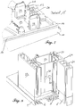
- eine perspektivische Ansicht in Form einer Explosionszeichnung mit Schwelle, Schwellenverbinder und Blendrahmenprofil,
- Fig. 2
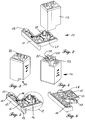
- den Schwellenverbinder vor dem Zusammenbau,
- Fig. 3
- den Füllkern in perspektivischer Ansicht von oben,
- Fig. 4
- den Füllkern in perspektivischer Ansicht von unten,
- Fig. 5
- den Schwellenhalter in perspektivischer Ansicht von oben,
- Fig. 6
- den Schwellenhalter in perspektivischer Ansicht von unten,
- Fig. 7
- Detail "C" gemäß
Fig. 5 , - Fig. 8
- die fertige Verbindung mit Schwelle, Schwellenverbinder und Blendrahmenprofil,
- Fig. 9
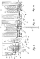
- einen Horizontalschnitt durch das mit der Schwelle verbundene Blendrahmenprofil,
- Fig. 10
- einen Vertikalschnitt "AA" gemäß
Fig. 9 vor dem Verschrauben, - Fig. 11
- einen Vertikalschnitt wie in
Fig. 10 nach dem Verschrauben. - In
Fig. 1 ist eine perspektivische Ansicht eines Systems in Form einer Explosionszeichnung mit Schwelle 1, dem aus Schwellenhalter 11 und Füllkern 12 bestehenden Schwellenverbinder 10 und dem als Z-förmiges Blendrahmenprofil aus Kunststoff extrudierten Hohlkammerprofil 20 vor der Montage dargestellt. Die Schwelle 1 ist in an sich bekannter Weise mehrteilig ausgeführt und umfasst im Wesentlichen den Schwellengrundkörper 2, die Kunststoffleiste 3 und den Schwellendeckel 4. - Der Schwellenverbinder 10 besteht im Wesentlichen aus dem den Grundkörper 13 bildenden Schwellenhalter 11 und dem Füllkern 12. Vor der Montage werden der Schwellenhalter 11 und der Füllkern 12 elastisch nachgiebig verbunden ("vormontierter Zustand"). Der Abstand zwischen der Unterseite des Füllkerns 12 und der Oberseite 14 des Schwellenhalters 11 beträgt im vormontierten Zustand 3,5 mm.
- In den
Fig. 2 bis 6 sind verschiedene perspektivische Ansichten des Schwellenhalters 11 und des Füllkerns 12 dargestellt. Der Füllkern 12 wird im Spritzgussverfahren aus thermoplastischem Kunststoff, beispielsweise ABS, Polycarbonat oder Hart-PVC, hergestellt. Eine zentrale Bohrung 33 nimmt bei der späteren Montage die Schraube 8 auf. - Auf der Unterseite (
Fig. 4 ) des Füllkerns 12 sind zwei Federstege 25 zu erkennen, die eine elastisch beabstandete Verbindung zwischen dem Füllkern 12 und dem Schwellenhalter 11 ermöglichen. Die Federstege 25 sind einstückig mit dem Füllkern 12 verbunden. In dem hier dargestellten Ausführungsbeispiel sind die Federstege 25 an beiden Enden mit dem Füllkern 12 verbunden, davon an einer Seite über eine Sollbruchstelle. Hierdurch wird erreicht, dass der Füllkern 12 nach dem Aufstecken auf den Schwellenhalter 11 zunächst relativ steif, jedoch beabstandet mit diesem verbunden ist. Beim späteren Anziehen der Schraube 8 bricht diese Sollbruchstelle, so dass die Federstege 25 nur noch einseitig mit dem Füllkern 12 verbunden sind und die Schraube 8 leichter eingedreht werden kann. - Der Schwellenhalter 11 weist auf seiner Oberseite 14 eine Vielzahl von Zentrierzapfen 19 auf, die bei der späteren Montage in verschiedene Hohlkammern des Hohlkammerprofils 20 eingreifen, an den Innenwänden dieser Hohlkammern anliegen und damit eine torsionssteife Verbindung zwischen dem Hohlkammerprofil 20 und der Schwelle 1 gewährleisten. Eine ähnliche Funktion übernehmen auch die beiden Führungszapfen 27 in Bezug auf eine torsionssteife Verbindung zwischen dem Schwellenhalter 11 und dem Füllkern 12.
- In
Fig. 7 ist das Detail "C" des Schwellenhalters 11 gemäßFig. 5 vergrößert dargestellt. Man erkennt auf der Oberseite 14 zwei Rasthaken 28, die bei der Vormontage des Schwellenverbinders 10, also beim Aufsetzen des Füllkerns 12 auf die Oberseite 14 des Schwellenhalters 11, hinter die zwei hinterschnittenen Stege 26 (Fig. 9 ) greifen. Die Länge dieser Rasthaken 28 und die Lage der beiden Stege 26 sind so ausgelegt, dass der durch die Federstege 25 bewirkte Abstand zwischen der Unterseite 34 des Füllkerns 12 und der Oberseite 14 des Schwellenhalters 11 ca. 3,5 mm beträgt und damit die Dichtung 16 im vormontierten Zustand noch nicht komprimiert wird. - Der Schwellenverbinder 10 wird zur Montage zunächst so auf die Oberseite 31 des Schwellengrundkörper 2 aufgesetzt, dass die auf der Unterseite 15 des Schwellenhalters 11 vorstehenden Zentrierzapfen 18 (
Fig. 6 ) in die Löcher 6 des Schwellengrundkörpers 2 eingreifen und beim Eindrehen der Schraube 32 in den Schwellengrundkörper 2 ein dichtendes Anpressen der Unterseite 15 unter Komprimierung der Dichtung 17 auf den Schwellengrundkörper 2 und in den Wirbelkanal 7 bewirkt wird. - Bei dem in
Fig. 1 dargestellten Ausführungsbeispiel wird zusätzlich eine Überschlagsabdeckung 5 verwendet, die den Schwellendeckel 4 im Endbereich der Schwelle 1 ersetzt und den inneren Überschlag 21 (Fig. 8 ) des Hohlkammerprofils 20 auf der Innenseite 24 nach unten hin abschließt. Die Überschlagsabdeckung 5 weist auf ihrer Oberseite mehrere Zentrierzapfen 29 auf, die beim späteren Aufsetzen des Hohlkammerprofils 20 in Hohlkammern des inneren Überschlags 21 des Hohlkammerprofils 20 eingreifen und die Torsionssteifigkeit der Verbindung weiter erhöhen. Die Befestigung der Überschlagsabdeckung 5 an der Schwelle 1 erfolgt mittels der beiden Schrauben 9. - Nach Befestigen des Schwellenverbinders 10 auf dem Schwellengrundkörper 2 wird das Hohlkammerprofil 20 mit seiner Stirnfläche so auf die Oberseite 14 des vormontierten Schwellenverbinders 10 gesetzt, dass der zu diesem Zeitpunkt noch nachgiebig beabstandet mit dem Schwellenhalter 11 verbundene Füllkern 12 vollständig in die Hohlkammer 22 ragt. Im nächsten Schritt wird durch Eindrehen der beiden Schrauben 30 durch die Wandung des Hohlkammerprofils 20 in den Füllkern 12 eine feste Verbindung zwischen Füllkern 12 und Hohlkammerprofil 20 hergestellt.
- Abschließend wird die zentrale Schraube 8 von der Unterseite des Schwellengrundkörpers 2 durch den Schwellenhalter 11 in den Füllkern 12 geschraubt. Da der Füllkern 12 mit seiner Unterseite 34 einerseits einen Abstand von ca. 3,5 mm zur Oberseite 14 des Schwellenhalters 11 aufweist und andererseits durch die Schrauben 30 fest mit dem Hohlkammerprofil 20 verbunden ist, wird beim Eindrehen der Schraube 8 in den Füllkern 12 das Hohlkammerprofil 20 mit seiner Stirnseite axial in Richtung der Oberseite 14 des Schwellenhalters 11 gezogen und die Dichtung 16 an die entsprechende Kontur der Stirnfläche des Hohlkammerprofils 20 gepresst. Hierbei wird die Dichtung 16 komprimiert und die Dichtfunktion hergestellt. Nach dem festen Anziehen der Schraube 8 kann, muss der Füllkern 12 die Oberseite 14 des Schwellenhalters 11 jedoch nicht berühren. Der ursprüngliche Abstand von ca. 3,5 mm zur Oberseite 14 des Schwellenhalters 11 ist vielmehr so ausgelegt, dass auch größere Toleranzen beim Einsetzen des Schwellenverbinders 10 mit dem Füllkern 12 in die Stirnseite des Hohlkammerprofils 20 ausgeglichen werden können.
- In den
Fig. 9 bis 11 ist die Schwellenverbindung mit dem Schwellenverbinder 10, dem Hohlkammerprofil 20 und der Schwelle 1 in verschiedenen Schnitten dargestellt. In denFig. 9 und 10 ist der Füllkern 12 bereits mit dem Hohlkammerprofil 20 mittels der beiden Schrauben 30 fest verbunden, jedoch noch um 3,5 mm beabstandet mit dem Schwellenhalter 11 durch die aus den Rasthaken 28 und den Stegen 26 bestehende Rastverbindung verbunden. Durch Eindrehen der Schraube 8 wird der Füllkern 12 und das damit fest verbundene Hohlkammerprofil 20 mit seiner Stirnseite auf die Oberseite 14 des Schwellenhalters 11 gezogen, wodurch die Dichtung 16 komprimiert und die Stirnseite des Hohlkammerprofils 20 fest auf die Oberseite 14 des Schwellenhalters 11 gepresst wird. Hierbei werden auch die beiden Federstege 25 elastisch verformt, wie inFig. 11 im Vergleich zurFig. 10 zu erkennen ist. - In
Fig. 8 ist schließlich die fertige Verbindung zwischen dem Hohlkammerprofil 20 und der Schwelle 1 in einer schrägen Ansicht von der Außenseite 23 dargestellt. Der die Schwelle 1 seitlich überragende innere Überschlag 21 liegt im eingebauten Zustand - wie insbesondere in Frankreich üblich - an der Innenwand eines Gebäudes an. -
- 1
- Schwelle
- 2
- Schwellengrundkörper
- 3
- Kunststoffleiste
- 4
- Schwellendeckel
- 5
- Überschlagsabdeckung
- 6
- Löcher
- 7
- Wirbelkanal
- 8
- Schraube
- 9
- Schrauben
- 10
- Schwellenverbinder
- 11
- Schwellenhalter
- 12
- Füllkern
- 13
- Grundkörper
- 14
- Oberseite
- 15
- Unterseite
- 16
- Dichtung (Oberseite)
- 17
- Dichtung (Unterseite)
- 18
- Zentrierzapfen (Unterseite)
- 19
- Zentrierzapfen (Oberseite)
- 20
- Hohlkammerprofil (Blendrahmenprofil)
- 21
- innerer Überschlag
- 22
- Hohlkammer
- 23
- Außenseite
- 24
- Innenseite
- 25
- Federstege
- 26
- Stege
- 27
- Führungszapfen
- 28
- Rasthaken
- 29
- Zentrierzapfen
- 30
- Schrauben
- 31
- Oberseite (Schwelle)
- 32
- Schraube
- 33
- Bohrung
- 34
- Unterseite (Füllkern)
Claims (8)
- Schwellenverbinder (10) zum Verbinden eines wenigstens eine Hohlkammer (22) aufweisenden Hohlkammerprofils (20) mit der Oberseite (31) einer Schwelle (1), umfassend wenigstens einen Schwellenhalter (11) und einen in die Hohlkammer einführbaren Füllkern (12), wobei der Schwellenhalter (11) auf seiner dem Füllkern (12) zugewandten Oberseite (14) eine Dichtung (16) aufweist, dadurch gekennzeichnet, dass der Füllkern (12) und/oder der Schwellenhalter (11) Mittel aufweisen, die eine nachgiebige, beabstandete Befestigung des Füllkerns (12) an dem Schwellenhalter (11) bewirken.
- Schwellenverbinder (10) nach Anspruch 1, gekennzeichnet durch Mittel zum festen Verbinden, insbesondere Verschrauben, des Füllkerns (12) mit dem Hohlkammerprofil (20).
- Schwellenverbinder (10) nach Anspruch 1 oder 2, dadurch gekennzeichnet, dass der Schwellenhalter (11) auf seiner der Schwelle (1) zugewandten Unterseite (15) eine Dichtung (17) aufweist.
- Schwellenverbinder (10) nach einem der Ansprüche 1 bis 3, dadurch gekennzeichnet, dass der Füllkern (12) aus Kunststoff besteht.
- Schwellenverbinder (10) nach einem der Ansprüche 1 bis 4, dadurch gekennzeichnet, dass die nachgiebige, beabstandete Befestigung des Füllkerns (12) an dem Schwellenhalter (11) elastisch ausgeführt ist.
- Schwellenverbinder (10) nach einem der Ansprüche 1 bis 5, dadurch gekennzeichnet, dass die nachgiebige, beabstandete Befestigung des Füllkerns (12) an dem Schwellenhalter (11) eine Sollbruchstelle aufweist.
- System umfassend eine Schwelle (1), ein Hohlkammerprofil (20) und einen mehrteiligen Schwellenverbinder nach einem der Ansprüche 1 bis 6.
- Verfahren zum Verbinden eines wenigstens eine Hohlkammer (22) aufweisenden Hohlkammerprofils (20) mit der Oberseite (31) einer Schwelle (1) unter Verwendung eines einen Füllkern (12) und einen Schwellenhalter (11) umfassenden Schwellenverbinders (10) nach einem der Ansprüche 1 bis 6, mit folgenden Verfahrensschritten:a) der Füllkern (12) wird mit dem Schwellenhalter (11) nachgiebig beabstandet verbunden;b) der Schwellenhalter (11) wird mit der Oberseite (31) der Schwelle (1) fest verbunden;c) das Hohlkammerprofil (20) wird auf den Schwellenverbinder (10) aufgesetzt bzw. der Füllkern (12) wird in die Hohlkammer (22) eingeführt;d) der Füllkern (12) wird - insbesondere durch eine Verschraubung (30) - fest mit dem Hohlkammerprofil (20) verbunden;e) mittels wenigstens einer Schraube (8), die von der Unterseite der Schwelle (1) durch den Schwellenhalter (11) in den Füllkern (12) geschraubt wird, wird das Hohlkammerprofil (20) auf die Oberseite (14) des Schwellenhalters (11) und/oder die zwischen dem Hohlkammerprofil (20) und der Oberseite (14) des Schwellenhalters (11) angeordnete Dichtung (16) gepresst, wobei sich der Abstand zwischen Füllkern (12) und Schwellenhalter (11) unter Komprimierung der Dichtung (16) verringert,
wobei die Verfahrensschritte a) und b) auch in umgekehrter Reihenfolge erfolgen können.
Applications Claiming Priority (1)
| Application Number | Priority Date | Filing Date | Title |
|---|---|---|---|
| EP16199343.1A EP3323971A1 (de) | 2016-11-17 | 2016-11-17 | Schwellenverbinder und dessen verwendung |
Publications (2)
| Publication Number | Publication Date |
|---|---|
| EP3323972A1 true EP3323972A1 (de) | 2018-05-23 |
| EP3323972B1 EP3323972B1 (de) | 2020-02-19 |
Family
ID=57345810
Family Applications (2)
| Application Number | Title | Priority Date | Filing Date |
|---|---|---|---|
| EP16199343.1A Withdrawn EP3323971A1 (de) | 2016-11-17 | 2016-11-17 | Schwellenverbinder und dessen verwendung |
| EP17202000.0A Active EP3323972B1 (de) | 2016-11-17 | 2017-11-16 | Schwellenverbinder und dessen verwendung |
Family Applications Before (1)
| Application Number | Title | Priority Date | Filing Date |
|---|---|---|---|
| EP16199343.1A Withdrawn EP3323971A1 (de) | 2016-11-17 | 2016-11-17 | Schwellenverbinder und dessen verwendung |
Country Status (2)
| Country | Link |
|---|---|
| EP (2) | EP3323971A1 (de) |
| DE (1) | DE102017126954A1 (de) |
Families Citing this family (1)
| Publication number | Priority date | Publication date | Assignee | Title |
|---|---|---|---|---|
| DE102023124133A1 (de) * | 2023-09-07 | 2025-03-13 | Maco Technologie Gmbh | Bodenschwelle |
Citations (4)
| Publication number | Priority date | Publication date | Assignee | Title |
|---|---|---|---|---|
| DE19734876A1 (de) | 1997-08-12 | 1999-02-18 | Peter Willrich | Verbindungselement zur Verbindung eines Hohlteils mit einem auf Stoß anliegenden Profilteil im Tür- oder Fensterbau |
| DE20022411U1 (de) | 2000-05-02 | 2001-08-16 | Deflex-Dichtsysteme Gmbh, 47059 Duisburg | Rahmen-Pfosten-Verbindung |
| DE202007015357U1 (de) | 2007-11-02 | 2009-03-19 | Rehau Ag + Co | Mechanischer Verbinder |
| WO2015011092A1 (de) | 2013-07-23 | 2015-01-29 | Profine Gmbh | System mit pfostenprofil, schwelle und schwellenhalter |
-
2016
- 2016-11-17 EP EP16199343.1A patent/EP3323971A1/de not_active Withdrawn
-
2017
- 2017-11-16 DE DE102017126954.1A patent/DE102017126954A1/de not_active Withdrawn
- 2017-11-16 EP EP17202000.0A patent/EP3323972B1/de active Active
Patent Citations (4)
| Publication number | Priority date | Publication date | Assignee | Title |
|---|---|---|---|---|
| DE19734876A1 (de) | 1997-08-12 | 1999-02-18 | Peter Willrich | Verbindungselement zur Verbindung eines Hohlteils mit einem auf Stoß anliegenden Profilteil im Tür- oder Fensterbau |
| DE20022411U1 (de) | 2000-05-02 | 2001-08-16 | Deflex-Dichtsysteme Gmbh, 47059 Duisburg | Rahmen-Pfosten-Verbindung |
| DE202007015357U1 (de) | 2007-11-02 | 2009-03-19 | Rehau Ag + Co | Mechanischer Verbinder |
| WO2015011092A1 (de) | 2013-07-23 | 2015-01-29 | Profine Gmbh | System mit pfostenprofil, schwelle und schwellenhalter |
Also Published As
| Publication number | Publication date |
|---|---|
| EP3323971A1 (de) | 2018-05-23 |
| DE102017126954A1 (de) | 2018-05-17 |
| EP3323972B1 (de) | 2020-02-19 |
Similar Documents
| Publication | Publication Date | Title |
|---|---|---|
| EP2834095B1 (de) | Profilelement zum verbinden einer fahrzeugscheibe mit einem abdeckteil und profilelementbaugruppe | |
| DE19930728B4 (de) | Dübel zum Befestigen eines Gegenstandes an einem Träger aus Flachmaterial | |
| EP3433912B1 (de) | Flachteilhalter für die befestigung eines flachteils an einem rahmengestell eines schaltschranks und ein entsprechender schaltschrank | |
| EP0569986A1 (de) | Verbindung für winklig aneinanderstossende Hohlprofilstäbe | |
| EP1405979B1 (de) | Verbindungsvorrichtung, Abdeckvorrichtung und Trennelement | |
| EP3025003B1 (de) | System mit pfostenprofil, schwelle und schwellenhalter | |
| EP1794030B1 (de) | Dachträgersystem für ein fahrzeug | |
| EP3014041A1 (de) | System zur herstellung eines türrahmens mit schwellenhalter | |
| DE19615378C2 (de) | Dichtkörper für einen Anschluß zwischen einem Pfostenprofil und einem Fenster- oder Türrahmenprofil | |
| DE102007057999B3 (de) | Öffenbares Fahrzeugdach | |
| EP3323972B1 (de) | Schwellenverbinder und dessen verwendung | |
| EP2088337A2 (de) | Profil und Profilsystem | |
| EP2746515A2 (de) | Vorsatzschale für eine Fenster- oder Türkonstruktion | |
| WO2015127924A1 (de) | Schaltschrank | |
| EP2047120A1 (de) | Befestigungsclip | |
| EP3692611B1 (de) | Anordnung zur positionierung eines flachteils an einem schaltschrankrahmengestell sowie ein entsprechendes verfahren | |
| EP1035294A2 (de) | Kämpferverbinder-Satz | |
| EP3745919A1 (de) | Schubladenseitenwand | |
| EP2055886A2 (de) | Mechanischer Verbinder | |
| DE102007034930A1 (de) | Isolierprofil, Verfahren zur Montage eines Isolierprofils sowie Stromschiene | |
| DE102013110832A1 (de) | Vorrichtung zur Abdichtung von Tür- oder Fensterelementen | |
| DE10212229A1 (de) | Schwellenverbinder | |
| EP1787002A1 (de) | Bauteilesatz aus wenigstens einer sprosse und wenigstens zwei sprossenendstücken zum einbauen in eine isolierglasscheibe | |
| EP2071992B1 (de) | Raumtrennvorrichtung, insbesondere Duschabtrennung | |
| EP2642040B1 (de) | Verbinder, Werkzeug zur Montage und Verwendung eines Verbinders |
Legal Events
| Date | Code | Title | Description |
|---|---|---|---|
| PUAI | Public reference made under article 153(3) epc to a published international application that has entered the european phase |
Free format text: ORIGINAL CODE: 0009012 |
|
| STAA | Information on the status of an ep patent application or granted ep patent |
Free format text: STATUS: THE APPLICATION HAS BEEN PUBLISHED |
|
| AK | Designated contracting states |
Kind code of ref document: A1 Designated state(s): AL AT BE BG CH CY CZ DE DK EE ES FI FR GB GR HR HU IE IS IT LI LT LU LV MC MK MT NL NO PL PT RO RS SE SI SK SM TR |
|
| AX | Request for extension of the european patent |
Extension state: BA ME |
|
| STAA | Information on the status of an ep patent application or granted ep patent |
Free format text: STATUS: REQUEST FOR EXAMINATION WAS MADE |
|
| 17P | Request for examination filed |
Effective date: 20181123 |
|
| RBV | Designated contracting states (corrected) |
Designated state(s): AL AT BE BG CH CY CZ DE DK EE ES FI FR GB GR HR HU IE IS IT LI LT LU LV MC MK MT NL NO PL PT RO RS SE SI SK SM TR |
|
| GRAP | Despatch of communication of intention to grant a patent |
Free format text: ORIGINAL CODE: EPIDOSNIGR1 |
|
| STAA | Information on the status of an ep patent application or granted ep patent |
Free format text: STATUS: GRANT OF PATENT IS INTENDED |
|
| INTG | Intention to grant announced |
Effective date: 20190906 |
|
| GRAS | Grant fee paid |
Free format text: ORIGINAL CODE: EPIDOSNIGR3 |
|
| GRAA | (expected) grant |
Free format text: ORIGINAL CODE: 0009210 |
|
| STAA | Information on the status of an ep patent application or granted ep patent |
Free format text: STATUS: THE PATENT HAS BEEN GRANTED |
|
| AK | Designated contracting states |
Kind code of ref document: B1 Designated state(s): AL AT BE BG CH CY CZ DE DK EE ES FI FR GB GR HR HU IE IS IT LI LT LU LV MC MK MT NL NO PL PT RO RS SE SI SK SM TR |
|
| REG | Reference to a national code |
Ref country code: CH Ref legal event code: EP |
|
| REG | Reference to a national code |
Ref country code: DE Ref legal event code: R096 Ref document number: 502017003852 Country of ref document: DE |
|
| REG | Reference to a national code |
Ref country code: CH Ref legal event code: NV Representative=s name: TR-IP CONSULTING LLC, CH |
|
| REG | Reference to a national code |
Ref country code: AT Ref legal event code: REF Ref document number: 1235152 Country of ref document: AT Kind code of ref document: T Effective date: 20200315 |
|
| REG | Reference to a national code |
Ref country code: IE Ref legal event code: FG4D Free format text: LANGUAGE OF EP DOCUMENT: GERMAN |
|
| REG | Reference to a national code |
Ref country code: NL Ref legal event code: MP Effective date: 20200219 |
|
| PG25 | Lapsed in a contracting state [announced via postgrant information from national office to epo] |
Ref country code: NO Free format text: LAPSE BECAUSE OF FAILURE TO SUBMIT A TRANSLATION OF THE DESCRIPTION OR TO PAY THE FEE WITHIN THE PRESCRIBED TIME-LIMIT Effective date: 20200519 Ref country code: FI Free format text: LAPSE BECAUSE OF FAILURE TO SUBMIT A TRANSLATION OF THE DESCRIPTION OR TO PAY THE FEE WITHIN THE PRESCRIBED TIME-LIMIT Effective date: 20200219 Ref country code: RS Free format text: LAPSE BECAUSE OF FAILURE TO SUBMIT A TRANSLATION OF THE DESCRIPTION OR TO PAY THE FEE WITHIN THE PRESCRIBED TIME-LIMIT Effective date: 20200219 |
|
| REG | Reference to a national code |
Ref country code: LT Ref legal event code: MG4D |
|
| PG25 | Lapsed in a contracting state [announced via postgrant information from national office to epo] |
Ref country code: LV Free format text: LAPSE BECAUSE OF FAILURE TO SUBMIT A TRANSLATION OF THE DESCRIPTION OR TO PAY THE FEE WITHIN THE PRESCRIBED TIME-LIMIT Effective date: 20200219 Ref country code: IS Free format text: LAPSE BECAUSE OF FAILURE TO SUBMIT A TRANSLATION OF THE DESCRIPTION OR TO PAY THE FEE WITHIN THE PRESCRIBED TIME-LIMIT Effective date: 20200619 Ref country code: SE Free format text: LAPSE BECAUSE OF FAILURE TO SUBMIT A TRANSLATION OF THE DESCRIPTION OR TO PAY THE FEE WITHIN THE PRESCRIBED TIME-LIMIT Effective date: 20200219 Ref country code: HR Free format text: LAPSE BECAUSE OF FAILURE TO SUBMIT A TRANSLATION OF THE DESCRIPTION OR TO PAY THE FEE WITHIN THE PRESCRIBED TIME-LIMIT Effective date: 20200219 Ref country code: GR Free format text: LAPSE BECAUSE OF FAILURE TO SUBMIT A TRANSLATION OF THE DESCRIPTION OR TO PAY THE FEE WITHIN THE PRESCRIBED TIME-LIMIT Effective date: 20200520 Ref country code: BG Free format text: LAPSE BECAUSE OF FAILURE TO SUBMIT A TRANSLATION OF THE DESCRIPTION OR TO PAY THE FEE WITHIN THE PRESCRIBED TIME-LIMIT Effective date: 20200519 |
|
| PG25 | Lapsed in a contracting state [announced via postgrant information from national office to epo] |
Ref country code: NL Free format text: LAPSE BECAUSE OF FAILURE TO SUBMIT A TRANSLATION OF THE DESCRIPTION OR TO PAY THE FEE WITHIN THE PRESCRIBED TIME-LIMIT Effective date: 20200219 |
|
| PG25 | Lapsed in a contracting state [announced via postgrant information from national office to epo] |
Ref country code: RO Free format text: LAPSE BECAUSE OF FAILURE TO SUBMIT A TRANSLATION OF THE DESCRIPTION OR TO PAY THE FEE WITHIN THE PRESCRIBED TIME-LIMIT Effective date: 20200219 Ref country code: ES Free format text: LAPSE BECAUSE OF FAILURE TO SUBMIT A TRANSLATION OF THE DESCRIPTION OR TO PAY THE FEE WITHIN THE PRESCRIBED TIME-LIMIT Effective date: 20200219 Ref country code: CZ Free format text: LAPSE BECAUSE OF FAILURE TO SUBMIT A TRANSLATION OF THE DESCRIPTION OR TO PAY THE FEE WITHIN THE PRESCRIBED TIME-LIMIT Effective date: 20200219 Ref country code: LT Free format text: LAPSE BECAUSE OF FAILURE TO SUBMIT A TRANSLATION OF THE DESCRIPTION OR TO PAY THE FEE WITHIN THE PRESCRIBED TIME-LIMIT Effective date: 20200219 Ref country code: DK Free format text: LAPSE BECAUSE OF FAILURE TO SUBMIT A TRANSLATION OF THE DESCRIPTION OR TO PAY THE FEE WITHIN THE PRESCRIBED TIME-LIMIT Effective date: 20200219 Ref country code: SM Free format text: LAPSE BECAUSE OF FAILURE TO SUBMIT A TRANSLATION OF THE DESCRIPTION OR TO PAY THE FEE WITHIN THE PRESCRIBED TIME-LIMIT Effective date: 20200219 Ref country code: EE Free format text: LAPSE BECAUSE OF FAILURE TO SUBMIT A TRANSLATION OF THE DESCRIPTION OR TO PAY THE FEE WITHIN THE PRESCRIBED TIME-LIMIT Effective date: 20200219 Ref country code: SK Free format text: LAPSE BECAUSE OF FAILURE TO SUBMIT A TRANSLATION OF THE DESCRIPTION OR TO PAY THE FEE WITHIN THE PRESCRIBED TIME-LIMIT Effective date: 20200219 Ref country code: PT Free format text: LAPSE BECAUSE OF FAILURE TO SUBMIT A TRANSLATION OF THE DESCRIPTION OR TO PAY THE FEE WITHIN THE PRESCRIBED TIME-LIMIT Effective date: 20200712 |
|
| REG | Reference to a national code |
Ref country code: DE Ref legal event code: R097 Ref document number: 502017003852 Country of ref document: DE |
|
| PLBE | No opposition filed within time limit |
Free format text: ORIGINAL CODE: 0009261 |
|
| STAA | Information on the status of an ep patent application or granted ep patent |
Free format text: STATUS: NO OPPOSITION FILED WITHIN TIME LIMIT |
|
| 26N | No opposition filed |
Effective date: 20201120 |
|
| PG25 | Lapsed in a contracting state [announced via postgrant information from national office to epo] |
Ref country code: SI Free format text: LAPSE BECAUSE OF FAILURE TO SUBMIT A TRANSLATION OF THE DESCRIPTION OR TO PAY THE FEE WITHIN THE PRESCRIBED TIME-LIMIT Effective date: 20200219 Ref country code: PL Free format text: LAPSE BECAUSE OF FAILURE TO SUBMIT A TRANSLATION OF THE DESCRIPTION OR TO PAY THE FEE WITHIN THE PRESCRIBED TIME-LIMIT Effective date: 20200219 |
|
| PG25 | Lapsed in a contracting state [announced via postgrant information from national office to epo] |
Ref country code: MC Free format text: LAPSE BECAUSE OF FAILURE TO SUBMIT A TRANSLATION OF THE DESCRIPTION OR TO PAY THE FEE WITHIN THE PRESCRIBED TIME-LIMIT Effective date: 20200219 |
|
| PG25 | Lapsed in a contracting state [announced via postgrant information from national office to epo] |
Ref country code: LU Free format text: LAPSE BECAUSE OF NON-PAYMENT OF DUE FEES Effective date: 20201116 |
|
| REG | Reference to a national code |
Ref country code: BE Ref legal event code: MM Effective date: 20201130 |
|
| PG25 | Lapsed in a contracting state [announced via postgrant information from national office to epo] |
Ref country code: IE Free format text: LAPSE BECAUSE OF NON-PAYMENT OF DUE FEES Effective date: 20201116 |
|
| PG25 | Lapsed in a contracting state [announced via postgrant information from national office to epo] |
Ref country code: TR Free format text: LAPSE BECAUSE OF FAILURE TO SUBMIT A TRANSLATION OF THE DESCRIPTION OR TO PAY THE FEE WITHIN THE PRESCRIBED TIME-LIMIT Effective date: 20200219 Ref country code: MT Free format text: LAPSE BECAUSE OF FAILURE TO SUBMIT A TRANSLATION OF THE DESCRIPTION OR TO PAY THE FEE WITHIN THE PRESCRIBED TIME-LIMIT Effective date: 20200219 Ref country code: CY Free format text: LAPSE BECAUSE OF FAILURE TO SUBMIT A TRANSLATION OF THE DESCRIPTION OR TO PAY THE FEE WITHIN THE PRESCRIBED TIME-LIMIT Effective date: 20200219 |
|
| PG25 | Lapsed in a contracting state [announced via postgrant information from national office to epo] |
Ref country code: MK Free format text: LAPSE BECAUSE OF FAILURE TO SUBMIT A TRANSLATION OF THE DESCRIPTION OR TO PAY THE FEE WITHIN THE PRESCRIBED TIME-LIMIT Effective date: 20200219 Ref country code: AL Free format text: LAPSE BECAUSE OF FAILURE TO SUBMIT A TRANSLATION OF THE DESCRIPTION OR TO PAY THE FEE WITHIN THE PRESCRIBED TIME-LIMIT Effective date: 20200219 |
|
| GBPC | Gb: european patent ceased through non-payment of renewal fee |
Effective date: 20211116 |
|
| PG25 | Lapsed in a contracting state [announced via postgrant information from national office to epo] |
Ref country code: BE Free format text: LAPSE BECAUSE OF NON-PAYMENT OF DUE FEES Effective date: 20201130 |
|
| PG25 | Lapsed in a contracting state [announced via postgrant information from national office to epo] |
Ref country code: GB Free format text: LAPSE BECAUSE OF NON-PAYMENT OF DUE FEES Effective date: 20211116 |
|
| REG | Reference to a national code |
Ref country code: DE Ref legal event code: R081 Ref document number: 502017003852 Country of ref document: DE Owner name: PROFINE GMBH, DE Free format text: FORMER OWNER: PROFINE GMBH, 53840 TROISDORF, DE |
|
| PGFP | Annual fee paid to national office [announced via postgrant information from national office to epo] |
Ref country code: AT Payment date: 20221121 Year of fee payment: 6 |
|
| PGFP | Annual fee paid to national office [announced via postgrant information from national office to epo] |
Ref country code: CH Payment date: 20221121 Year of fee payment: 6 |
|
| REG | Reference to a national code |
Ref country code: CH Ref legal event code: PL |
|
| REG | Reference to a national code |
Ref country code: AT Ref legal event code: MM01 Ref document number: 1235152 Country of ref document: AT Kind code of ref document: T Effective date: 20231116 |
|
| PG25 | Lapsed in a contracting state [announced via postgrant information from national office to epo] |
Ref country code: CH Free format text: LAPSE BECAUSE OF NON-PAYMENT OF DUE FEES Effective date: 20231130 |
|
| PG25 | Lapsed in a contracting state [announced via postgrant information from national office to epo] |
Ref country code: AT Free format text: LAPSE BECAUSE OF NON-PAYMENT OF DUE FEES Effective date: 20231116 |
|
| PG25 | Lapsed in a contracting state [announced via postgrant information from national office to epo] |
Ref country code: CH Free format text: LAPSE BECAUSE OF NON-PAYMENT OF DUE FEES Effective date: 20231130 Ref country code: AT Free format text: LAPSE BECAUSE OF NON-PAYMENT OF DUE FEES Effective date: 20231116 |
|
| PGFP | Annual fee paid to national office [announced via postgrant information from national office to epo] |
Ref country code: DE Payment date: 20251119 Year of fee payment: 9 |
|
| PGFP | Annual fee paid to national office [announced via postgrant information from national office to epo] |
Ref country code: IT Payment date: 20251125 Year of fee payment: 9 |
|
| PGFP | Annual fee paid to national office [announced via postgrant information from national office to epo] |
Ref country code: FR Payment date: 20251126 Year of fee payment: 9 |