EP3323931B1 - Wäscheständer zum aufhängen und trocknen von wäsche - Google Patents
Wäscheständer zum aufhängen und trocknen von wäsche Download PDFInfo
- Publication number
- EP3323931B1 EP3323931B1 EP17189642.6A EP17189642A EP3323931B1 EP 3323931 B1 EP3323931 B1 EP 3323931B1 EP 17189642 A EP17189642 A EP 17189642A EP 3323931 B1 EP3323931 B1 EP 3323931B1
- Authority
- EP
- European Patent Office
- Prior art keywords
- laundry
- rack
- grids
- bars
- another
- Prior art date
- Legal status (The legal status is an assumption and is not a legal conclusion. Google has not performed a legal analysis and makes no representation as to the accuracy of the status listed.)
- Active
Links
- 238000001035 drying Methods 0.000 title claims description 33
- 238000010276 construction Methods 0.000 claims description 7
- NJPPVKZQTLUDBO-UHFFFAOYSA-N novaluron Chemical compound C1=C(Cl)C(OC(F)(F)C(OC(F)(F)F)F)=CC=C1NC(=O)NC(=O)C1=C(F)C=CC=C1F NJPPVKZQTLUDBO-UHFFFAOYSA-N 0.000 description 3
- 238000004026 adhesive bonding Methods 0.000 description 1
- 230000008878 coupling Effects 0.000 description 1
- 238000010168 coupling process Methods 0.000 description 1
- 238000005859 coupling reaction Methods 0.000 description 1
- 230000001419 dependent effect Effects 0.000 description 1
- 238000006073 displacement reaction Methods 0.000 description 1
- 230000000694 effects Effects 0.000 description 1
- 238000009434 installation Methods 0.000 description 1
- 238000000034 method Methods 0.000 description 1
- 238000003466 welding Methods 0.000 description 1
Images
Classifications
-
- D—TEXTILES; PAPER
- D06—TREATMENT OF TEXTILES OR THE LIKE; LAUNDERING; FLEXIBLE MATERIALS NOT OTHERWISE PROVIDED FOR
- D06F—LAUNDERING, DRYING, IRONING, PRESSING OR FOLDING TEXTILE ARTICLES
- D06F57/00—Supporting means, other than simple clothes-lines, for linen or garments to be dried or aired
- D06F57/08—Folding stands
Definitions
- the invention relates to a drying rack for hanging and drying laundry.
- Drying racks for drying laundry are known from the prior art. Arrangements of this type, which are also referred to as laundry drying racks or drying rack arrangements, are widespread household aids and typically have a collapsible base frame with two legs for setting up on a base. Also known are pull-out drying racks to increase the area for hanging the laundry.
- the EP 2208820 A1 , DE 10161319 A1 , EP 0609476 A1 , DE 202008003345 U1 and the DE 202004011846 U1 reveal drying rack.
- EP 2208820 A1 discloses a drying rack with a foldable support frame and two laundry racks, which are mounted on the support frame so that they can be displaced relative to the support frame and are coupled to one another in such a way that the two laundry racks can be displaced relative to one another between a first, pushed-together end position and a second, extended end position.
- An object on which the invention is based is to describe a concept for a clothes horse that allows for a particularly flexible use of the clothes horse and a high level of individual adaptability with regard to a usable area for hanging laundry.
- a drying rack for hanging and drying laundry has a foldable Support frame and only two laundry racks for receiving items of laundry.
- the laundry grate each have a transverse bar from which several parallel laundry rods extend.
- the two laundry racks are mounted on the support frame so that they can be displaced relative to the support frame.
- the two laundry grates are coupled to one another in such a way that the two laundry grates can be displaced relative to one another between a first end position pushed together and a second end position pulled apart.
- the laundry rods of both laundry grids are aligned coaxially with one another and are connected to one another.
- the laundry rods of both laundry gratings are at least partially arranged so that they can be pushed into one another.
- Each laundry grate has two outer laundry rods and several inner laundry rods, and the inner laundry rods are each connected to one another via a tubular connecting element as a guide and/or stability aid.
- the drying rack can also be referred to as an extendable drying rack and enables particularly flexible use.
- a first usable lattice area in the first end position of the two laundry fences can easily be enlarged towards a second usable lattice area in the second end position of the two laundry lattice.
- a simple structure and simple assembly are given, as explained below.
- the laundry stand provides only two laundry racks, which are arranged or mounted such that they can be displaced relative to one another and also with respect to the support frame.
- a fixed main grid that is stationary with respect to the carrier frame, including a frame that surrounds it on four sides. This becomes a particularly easy constructed, inexpensive and easy-to-assemble drying rack.
- the usable area of the grid is not interrupted in the longitudinal direction of the laundry rods, so that particularly large, wide items of laundry can be hung up.
- the support frame is a base frame or pedestal of the drying rack, which carries the two laundry grids or on which the two grids are supported.
- the support frame has two pairs of legs or pairs of stands for setting up the drying rack.
- the support frame can be folded up so that the drying rack can be easily folded up and stowed away to save space.
- the laundry grids form a common level, such as the grid usable area, laundry usable area or levels of the same name.
- the laundry racks are pivotably mechanically coupled to the support frame, so that the support frame can essentially be folded into the common plane.
- the two laundry racks are designed to correspond to each other and have the same number of laundry rods.
- each rod of a lattice forms a pair of laundry rods or a common laundry rod with another rod.
- Each lattice has a transverse bar, also called a transverse strut or transverse frame element, on which the laundry rods are fixed perpendicularly to a main extension of the transverse bar.
- transverse bars also called a transverse strut or transverse frame element
- the laundry rods are fixed perpendicularly to a main extension of the transverse bar.
- On the side of the rods facing away from the transverse beam these are exposed or have free ends.
- the attachment to the crossbars can be done in different ways, for example by means of screw connections.
- the transverse bars are on the outside, while the free ends point toward a center. In other words, the free ends of one lattice point in the direction of the cross bar of the other lattice.
- the shifting of the lattice relative to one another means that they can be shifted in the longitudinal direction of the laundry rods.
- the shifting takes place within mechanically specified limits, for example by means of locking devices or stop elements.
- In the first end position the two grids are maximally pushed together, while in the second end position, the two grids are maximally pulled apart.
- the transverse beams can serve as a pulling or sliding aid and can be designed accordingly.
- Each clothes rack has two outer clothes rods and several inner clothes rods and the inner clothes rods are each connected to one another via a tubular connecting element.
- the tubular connecting element is, for example, a one-piece plastic element that represents a guide and/or stability aid for the clothes rods.
- the two laundry racks can be positioned independently of one another. As mentioned above, this is possible at least within predetermined limits, for example. In other words, for example, only the first laundry rack can be pulled out of the first position. This contributes to the flexible usability of the drying rack. In particular, spatial conditions at the installation site of the stand can be taken into account.
- the laundry rods of both laundry grids are aligned coaxially with one another and are connected to one another. This means that the laundry rods are aligned with each other.
- the clothes rods form common, continuous clothes rods.
- the connection can take place indirectly, for example via further pipe elements or connecting elements, or directly, for example directly. Due to the coaxial arrangement, the rods can be inserted into each other, so that a high level of stability can be achieved.
- the clothes rods of both clothes rails are telescopically connected.
- the laundry rods of the laundry grate are at least partially pushed into one another or are arranged such that they can be pushed into one another. At least in the pushed together position, the rods are arranged one inside the other. In the second end position, the sticks can, but no longer have to be inserted into one another, these being held in alignment with one another in the latter variant, for example by means of an additional connecting element.
- the staffs are always connected to form common staffs. Pushing or inserting into one another means that the two laundry racks are pushed into one another in the longitudinal direction of the laundry rods. In other words, the bars overlap in the axial direction.
- the outer diameters of the rods are adjusted accordingly. For example, the outer diameter of one lattice is slightly smaller than that of the other lattice, so that the rods can dip into one another.
- the laundry rods of the laundry grate are tubular, in particular hollow tubular. This allows the rods to be guided into one another.
- the tubular connecting elements are fixed to the inner clothes rods of one clothes fence and the inner clothes rods of the other clothes fence are at least partially accommodated in the connection elements.
- partially means the axial direction of the laundry rods.
- the outer laundry rods are mechanically more stable than the inner laundry rods. This allows the two grids to be securely supported or stored on the support frame.
- the outer bars form stiffer side frame members, particularly longitudinal members.
- two opposite, tubular longitudinal frame elements are arranged in a stationary manner on the support frame, into which outer laundry rods of the laundry grids are inserted.
- the longitudinal frame element is open on both sides. Together with the longitudinal frame elements, the outer laundry rods of the laundry rack form a laundry rod, although there may be slight differences in diameter analogous to the above.
- the longitudinal frame element can, for example, be designed to be particularly stiff and mechanically stable.
- the support frame together with the longitudinal frame elements forms a support structure on which the two laundry racks are held in a displaceable manner.
- each longitudinal frame element is pivotally coupled to the support frame via two fastening elements. Similar to the above (connecting elements), this is a plastic element, for example, which also has a pivoting mount for the carrier frame.
- the fastening elements each have a tubular section in which an end of a longitudinal frame element and an outer clothes rod of a clothes rack are accommodated.
- each outer laundry rod is guided over the fastening element on the longitudinal frame element and can be pushed or pushed into it.
- the foldable support frame is formed by a scissor-like stand construction.
- a scissor-like stand construction is particularly easy to fold and allows a very space-saving storage of the drying rack. Due to the relative displaceability of all two laundry grates with respect to the support frame, the use of such a base frame is made possible, which would not be possible in the case of an extendable grate in which the grates are not slidably guided on the support frame.
- the scissor-like stand construction is formed by two U-shaped brackets, each having two opposite legs and a bottom cross member connecting the two legs, free ends of the legs being pivotally coupled to the clothes rails.
- the mechanical coupling can be implemented directly or indirectly.
- the free legs are pivotally connected to the fastening element.
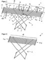
- Figures 1 and 2 show two functional states of a pull-out drying rack 1.
- the drying rack 1 has a collapsible support frame 2, which is a pedestal with two legs 3.
- Each leg 3 is formed as a U-shaped bracket having two opposite legs 4 and a bottom cross member 5 connecting the two legs 4 .
- the legs 4 are designed in two parts for a leg 3 .
- two leg elements 4A and 4B are mechanically connected via a joint element 5, which is folded in between the shown and a not shown state is adjustable, so that the pedestal 2 can be folded into one plane (not shown).
- foot caps can be provided in the corner areas, which serve as protection for the ground and/or the legs.
- fasteners 8 are pivotally mounted.
- the fasteners 8 are made of plastic in one piece.
- two fastening elements 8 are arranged on each of the two longitudinal sides 9 of the drying rack 1 .
- the fastening elements 8 have a continuous tubular section which can also be stepped with regard to an inner diameter.
- a hollow tubular longitudinal frame member 10 is inserted and fixed in the tubular portion of the two respective fasteners.
- the longitudinal frame element 10 is non-positively fixed in the tubular sections in the manner of a press fit.
- the longitudinal frame elements 10 are arranged in a stationary manner with respect to the support frame 2 and define a working plane E or working area in which the laundry is hung.
- the clothes horse 1 also has two clothes rails 11 constructed in a manner corresponding to one another, of which a first clothes rail 11A is arranged on the left and a second clothes rail 11B is arranged on the right. Both laundry grids 11 each have a transverse bar 12 from which a plurality of tubular laundry rods 13 extend perpendicularly to a main extension direction of the transverse bar 12 . The laundry rods 13 run parallel to one another. The laundry rods are divided into two outer laundry rods 13A and several inner laundry rods 13I per laundry grid 11 .
- tubular connecting elements 15 are fixed at the free ends 14 of the inner laundry rods 13I.
- the fixation can take place analogously to the above fastening elements 8 by means of a press fit, but as above, other connection techniques, for example materially bonded such as gluing or welding, are also possible.
- the connecting elements 15 are made in one piece from plastic.
- the laundry racks 11 are now attached to one another and to the support frame 2 in such a way that they are plugged together or brought together with the free ends 14 directed toward one another.
- the laundry rods 13 of the laundry grid 11 and the longitudinal frame elements 10 are aligned coaxially with one another.
- the outer laundry rods 13A are each guided into the fastening elements 8 and the inner rods 13I are mechanically coupled to one another via the connecting elements 15 .
- the clothes rails 11 can thus be pushed together or pulled apart relative to one another, with the clothes rods 13 of the second grid 11B being guided further into the clothes rods 13 of the first grid 11A. This increases an axial degree of overlap. This takes place within predetermined limits, which can be mechanically defined by means of locking or stop elements (not shown).
- the laundry rods 13 of both grids 11 and the longitudinal frame elements 10 are correspondingly adapted in terms of their outer and inner diameters such that the rods 13 can be pushed into one another or into the longitudinal frame elements 10 .
- the outer clothes rods 13A can be shorter in length than the inner ones Rods 13I be formed.
- the outer rods 13A can also be designed to be more stable, for example more rigid, so that the laundry racks 11 are securely mounted and guided via the longitudinal frame element 10 on the support frame.
- the two laundry grids 11 are thus mechanically connected to one another and mounted on the support frame 2, in which the grids are accommodated in the longitudinal frame elements 10 via the outer laundry rods 13A.
- the inner rods 13I and the outer rods 13A together with the longitudinal frame elements 10 each form common, continuous laundry rods 16, which extend between the transverse sides 17 of the drying rack 1, i.e. from the transverse bar 12 of the first laundry rack 11A to the transverse bar 12 of the second laundry rack 11B .
- the two laundry gratings 11 thus form a grating useful area 18 in the useful plane E, in which laundry can be hung.
- the laundry grate 11 can be displaced relative to one another, with the gratings 11 being able to be positioned independently of one another. Furthermore, the laundry racks 11 are mounted to be displaceable relative to the support frame 2 . This allows the high flexibility and adaptability of the drying rack 1 described at the outset.
- the grids 11 can thus be easily shifted between a first end position, in which the usable grid area 18 is maximum, and a second end position, in which the usable grid area 18 is minimal will.
- the displacement is stepless and can be achieved, for example, by gripping and pushing the transverse bars 12 .
- figure 1 shows a first functional state of the clothes horse 1, in which the first end position of the clothes rack 11 is shown.
- figure 2 shows a second functional state of the stand 1, wherein the effective grid area 18 is reduced. It should be noted that in figure 2 almost all reference symbols have been omitted for reasons of clarity.
- the laundry racks 11 would be pushed into one another in such a way that transverse bars 12 strike against the fastening elements 8 .
- the grid usable area 18 corresponds approximately to an area that is spanned by the longitudinal frame elements 10 and the transverse bars.
- the rods 13 of one grid 11 are always at least partially inserted into the rods 13 of the other grid.
- the bars cannot overlap axially either, with the free ends 14 only being arranged in the connecting elements 15 and only being guided into the bars 13 of the other grid 11 when they are pushed together.
- the grid usable area 18 is never interrupted by additional transverse struts. In other words, only one length of each laundry rod 16 formed together is varied. This means that individually different sized items of laundry can be hung up without interruption. Furthermore, the support frame 2 does not have to be adjusted in order to adjust the useful grid area 18 . A claimed footprint of the support frame 2 always remains the same. As a result, the scissors-like construction shown can be realized. However, other foot constructions are also conceivable.
Description
- Die Erfindung betrifft einen Wäscheständer zum Aufhängen und Trocknen von Wäsche.
- Wäscheständer zum Trocknen von Wäsche sind aus dem Stand der Technik bekannt. Derartige Anordnungen, welche auch als Wäschetrockengestelle oder Wäscheständeranordnungen bezeichnet werden, sind vielverbreitete Haushaltshilfen und weisen typischerweise ein zusammenklappbares Grundgestell mit zwei Standbeinen zum Aufstellen auf einem Untergrund auf. Bekannt sind auch ausziehbare Wäscheständer, um eine Fläche zum Aufhängen der Wäsche zu vergrößern. Die
EP 2208820 A1 ,DE 10161319 A1 ,EP 0609476 A1 ,DE 202008003345 U1 und dieDE 202004011846 U1 offenbaren Wäscheständer. Insbesondere dieEP 2208820 A1 offenbart einen Wäscheständer mit klappbaren Trägergestell und zwei Wäschegittern, die relativ zu dem Trägergestell verschiebbar an dem Trägergestell gelagert und derart miteinander gekoppelt sind, dass die beiden Wäschegitter relativ zueinander zwischen einer ersten, zusammengeschobenen Endposition und einer zweiten, auseinandergezogenen Endposition verschiebbar sind. - Eine Aufgabe, welche der Erfindung zugrunde liegt, ist es, ein Konzept für einen Wäscheständer zu beschreiben, welches eine besonders flexible Verwendbarkeit des Wäscheständers und eine hohe individuelle Anpassbarkeit hinsichtlich einer Nutzfläche zum Aufhängen von Wäsche ermöglicht.
- Es wird ein Wäscheständer zum Aufhängen und Trocknen von Wäsche offenbart. Der Wäscheständer weist ein klappbares Trägergestell und lediglich zwei Wäschegitter zum Aufnehmen von Wäschestücken auf. Die Wäschegitter weisen jeweils einen Querholm auf, von dem sich mehrere, zueinander parallele Wäschestäbe erstrecken. Die beiden Wäschegitter sind relativ zu dem Trägergestell verschiebbar an dem Trägergestell gelagert. Weiterhin sind die beiden Wäschegitter derart miteinander gekoppelt, dass die beiden Wäschegitter relativ zueinander zwischen einer ersten, zusammengeschobenen Endposition und einer zweiten, auseinandergezogenen Endposition verschiebbar sind. Die Wäschestäbe beider Wäschegitter sind koaxial zueinander ausgerichtet und miteinander verbunden. Die Wäschestäbe beider Wäschegitter sind zumindest teilweise ineinander schiebbar angeordnet. Jedes Wäschegitter weist zwei äußere Wäschestäbe und mehrere innere Wäschestäbe auf und die inneren Wäschestäbe sind über jeweils ein rohrförmiges Verbindungselement als Führung und/oder Stabilitätshilfe miteinander verbunden.
- Der Wäscheständer kann auch als ausziehbarer Wäscheständer bezeichnet werden und ermöglicht eine besonders flexible Verwendung. Es kann einfach eine erste Gitternutzfläche in der ersten Endposition der beiden Wäschegitter hin zu einer zweiten Gitternutzfläche in der zweiten Endposition der beiden Wäschegitter vergrößert werden kann. Dabei sind ein einfacher Aufbau und eine einfache Montierbarkeit gegeben, wie nachfolgend erläutert.
- Der Wäscheständer sieht lediglich zwei Wäschegitter vor, die jeweils zueinander als auch bezüglich des Trägergestells relativ verschiebbar angeordnet sind oder gelagert sind. Somit ist kein feststehendes, bezüglich des Trägergestells ortsfestes Hauptgitter inklusive von vier Seiten umgebenden Rahmen nötig. Dadurch wird zu einem besonders einfach aufgebauten, kostengünstigen und einfach zu montierenden Wäscheständer beigetragen.
- Weiterhin sind keine Querstreben außer den beiden Querholmen, die den Wäscheständer entsprechend der eingestellten Gitternutzfläche seitlich begrenzen, nötig. Auch dies trägt zur Einfachheit des Ständers bei. Zudem wird die Gitternutzfläche in Längsrichtung der Wäschestäbe nicht unterbrochen, so dass besonders große, breite Wäscheteile aufhängbar sind.
- Durch das Verschieben kann die Gitternutzfläche vergrößert oder verkleinert werden. Das Verschieben kann frei wählbar und somit eine Anpassung der Gitternutzfläche stufenlos erfolgen. Dies ermöglicht eine hohe individuelle Anpassbarkeit hinsichtlich der Gitternutzfläche zum Aufhängen von Wäsche.
- Dadurch, dass alle Wäschegitter relativ zum Trägergestell verschiebbar sind, bleibt eine Standfläche für den Wäscheständer unverändert. Zum Ausziehen der Wäschegitter müssen beispielsweise ein oder mehrere Ständerbeine nicht verschoben und mitausgezogen werden.
- Bei dem Trägergestell handelt es sich um ein Grundgestell oder Fußgestell des Wäscheständers, welches die beiden Wäschegitter trägt bzw. auf welchem die beiden Gitter abgestützt sind. Beispielsweise hat das Trägergestell zwei Beinpaare oder Ständerpaare zum Aufstellen des Wäscheständers. Das Trägergestell ist zusammenklappbar, so dass der Wäscheständer einfach zusammengeklappt und platzsparend verstaut werden kann.
- Die Wäschegitter bilden eine gemeinsame Ebene, etwa die Gitternutzfläche, Wäschenutzfläche oder gleichnamige Ebenen. Die Wäschegitter sind schwenkbar mit dem Trägergestell mechanisch gekoppelt, so dass das Trägergestell im Wesentlichen in die gemeinsame Ebene klappbar ist.
- Die beiden Wäschegitter sind korrespondierend zueinander aufgebaut und haben die gleiche Anzahl an Wäschestäben. Dies heißt, jeder Stab eines Gitters bildet mit einem anderen Stab ein Wäschestabpaar oder einen gemeinsamen Wäschestab. Jedes Gitter hat einen Querholm, auch Querstrebe oder Querrahmenelement genannt, an dem senkrecht zu einer Haupterstreckung des Querholms die Wäschestäbe festgelegt sind. An der dem Querholm abgewandten Seite der Stäbe sind diese freiliegend bzw. weisen freie Enden auf. Die Befestigung an den Querholmen kann auf verschiedene Arten geschehen, etwa mittels Verschraubungen. Im montierten Zustand des Wäscheständers sind die Querholme außen, während die freien Enden zu einer Mitte weisen. Mit anderen Worten zeigen die freien Enden des einen Gitters in Richtung des Querholms des anderen Gitters.
- Das Verschieben der Gitter zueinander bedeutet, dass diese in Längsrichtung der Wäschestäbe verschiebbar sind. Das Verschieben erfolgt innerhalb mechanisch vorgegebener Grenzen, etwa mittels Feststellvorrichtungen oder Anschlagselementen. In der ersten Endposition sind die beiden Gitter maximal zusammengeschoben, während in der zweiten Endposition die beiden Gitter maximal weiter auseinandergezogen sind. Die Querholme können als Zieh- bzw. Verschiebehilfe dienen und entsprechend ausgebildet sein. Jedes Wäschegitter weist zwei äußere Wäschestäbe und mehrere innere Wäschestäbe auf und die inneren Wäschestäbe sind über jeweils ein rohrförmiges Verbindungselement miteinander verbunden. Bei dem rohrförmigen Verbindungselement handelt es sich beispielsweise um ein einstückiges Kunststoffelement, welches eine Führung und/oder Stabilitätshilfe für die Wäschestäbe darstellt.
- Gemäß einer Ausführungsform sind die beiden Wäschegitter unabhängig voneinander positionierbar. Wie oben erwähnt ist das beispielsweise zumindest innerhalb vorgegebener Grenzen möglich. Mit anderen Worten kann beispielsweise nur das erste Wäschegitter ausgezogen werden aus der ersten Position. Dies trägt zu der flexiblen Verwendbarkeit des Wäscheständers bei. Insbesondere kann dadurch räumlichen Gegebenheiten am Aufstellort des Ständers Rechnung getragen werden.
- Die Wäschestäbe beider Wäschegitter sind koaxial zueinander ausgerichtet und miteinander verbunden. Dies bedeutet, dass die Wäschestäbe fluchtend zueinander angeordnet sind. Die Wäschestäbe bilden gemeinsame, durchgehende Wäschestäbe. Das Verbinden kann mittelbar, etwa über weitere Rohrelemente oder Verbindungselemente, oder unmittelbar, etwa direkt, erfolgen. Durch die koaxiale Anordnung können die Stäbe ineinander eingeführt werden, so dass eine hohe Stabilität erreichbar ist.
- Die Wäschestäbe beider Wäschegitter teleskopisch verbunden. Mit anderen Worten sind die Wäschestäbe der Wäschegitter zumindest teilweise ineinander eingeschoben oder ineinander einschiebbar angeordnet. Zumindest in der zusammengeschobenen Position sind die Stäbe ineinander angeordnet. In der zweiten Endposition können, aber müssen die Stäbe nicht mehr ineinander eingeführt sein, wobei diese in letzterer Variante fluchtend zueinander gehalten sind, etwa mittels eines zusätzlichen Verbindungselements. Stets sind die Stäbe zur Bildung gemeinsamer Stäbe verbunden. Ineinanderschieben oder ineinander einführen bedeutet, dass die beiden Wäschegitter in Längsrichtung der Wäschestäbe ineinandergeschoben sind. Anders ausgedrückt überlappen sich die Stäbe in axialer Richtung. Dabei sind Außendurchmesser der Stäbe entsprechend angepasst. Etwa sind die Außendurchmesser des einen Gitters etwas kleiner als die des anderen Gitters, so dass Stäbe ineinander eintauchen können.
- Gemäß einer Ausführungsform sind die Wäschestäbe der Wäschegitter rohrförmig, insbesondere hohlrohrförmig, ausgebildet sind. Dadurch können die Stäbe ineinander geführt werden.
- Gemäß einer Ausführungsform sind die rohrförmigen Verbindungselemente an den inneren Wäschestäbe des einen Wäschegitters festgelegt und die inneren Wäschestäbe des anderen Wäschegitters zumindest teilweise in den Verbindungselementen aufgenommen sind. Teilweise heißt bezüglich einer Längserstreckung, axialen Richtung der Wäschestäbe. Dadurch sind die Wäschestäbe gegenseitig stabil geführt, so dass diese gegeneinander sicher verschiebbar sind.
- Gemäß einer Ausführungsform sind die äußeren Wäschestäbe im Vergleich zu den inneren Wäschestäben mechanisch stabiler ausgebildet. Dadurch können die beiden Gitter sicher am Trägergestell abgestützt oder gelagert werden. Die äußeren Stäbe bilden beispielsweise steifere Seitenrahmenelemente, insbesondere Längselemente.
- Gemäß einer Ausführungsform sind an dem Trägergestell zwei gegenüberliegende, rohrförmige Längsrahmenelemente ortsfest angeordnet, in die jeweils äußere Wäschestäbe der Wäschegitter eingeführt sind. Das Längsrahmenelement ist jeweils zu beiden Seiten in offen. Die äußeren Wäschestäbe der Wäschegitter bilden mit den Längsrahmenelementen zusammen einen Wäschestab, wobei leichte Unterschiede im Durchmesser analog zu oben vorhanden sein können. Das Längsrahmenelement kann beispielsweise besonders steif und mechanisch stabil ausgeführt sein. Beispielsweise bildet das Trägergestell zusammen mit den Längsrahmenelementen eine Tragestruktur, an der die beiden Wäschegitter verschiebbar gehalten sind.
- Gemäß einer Ausführungsform ist jedes Längsrahmenelement über zwei Befestigungselemente schwenkbar mit dem Trägergestell gekoppelt. Analog zu oben (Verbindungselemente) handelt es sich beispielsweise um Kunststoffelement, welches zudem eine schwenkbare Aufnahme für das Trägergestell hat.
- Gemäß einer Ausführungsform weisen die Befestigungselemente jeweils einen rohrförmigen Abschnitt auf, in dem ein Ende eines Längsrahmenelements und ein äußerer Wäschestab eines Wäschegitters aufgenommen sind. Dadurch ist jeder äußerer Wäschestab über das Befestigungselement an dem Längsrahmenelement geführt und in dieses einschiebbar bzw. eingeschoben.
- Gemäß einer Ausführungsform ist das klappbare Trägergestell durch eine scherenförmige Ständerkonstruktion gebildet. Eine derartige Konstruktion ist besonders gut einklappbar und ermöglicht eine sehr platzsparende Aufbewahrung des Wäscheständers. Aufgrund der relativen Verschiebbarkeit aller zwei Wäschegitter bezüglich des Trägergestells ist der Einsatz eines solchen Fußgestells ermöglicht, welches im Falle eines ausziehbaren Gitters, bei dem die Gitter nicht verschiebbar am Trägergestell geführt sind, nicht umsetzbar wäre.
- Gemäß einer Ausführungsform ist die scherenförmige Ständerkonstruktion durch zwei U-förmige Bügel gebildet, die jeweils zwei gegenüberliegende Schenkel und ein Bodenquerelement, welches die beiden Schenkel verbindet, aufweisen, wobei freie Enden der Schenkel schwenkbar mit den Wäschegittern gekoppelt sind. Analog zu oben kann die mechanische Kopplung direkt oder mittelbar realisiert sein. Etwa sind die freien Schenkel schwenkbar an dem Befestigungselement angebunden.
- Weitere vorteilhafte Ausgestaltungen sind in den Unteransprüchen und in der nachfolgenden, ausführlichen Beschreibung eines Ausführungsbeispiels offenbart.
- Das Ausführungsbeispiel wird unter Zuhilfenahme der angehängten Figuren nachfolgend beschrieben. Gleichartige oder gleich wirkende Elemente sind figurenübergreifend mit den gleichen Bezugszeichen versehen.
- In den Figuren zeigen:
-
Figur 1 eine schematische, perspektivische Ansicht eines ausziehbaren Wäscheständers gemäß einem Ausführungsbeispiel mit Wäschegittern in einem ersten Funktionszustand und -
Figur 2 eine schematische, perspektivische Ansicht des Wäscheständers in einem zweiten Funktionszustand. -
Figuren 1 und 2 zeigen zwei Funktionszustände eines ausziehbaren Wäscheständers 1. - Der Wäscheständer 1 hat ein zusammenklappbares Trägergestell 2, welches ein Fußgestell mit zwei Standbeinen 3 ist. Jedes Standbein 3 ist als U-förmiger Bügel gebildet, der zwei gegenüberliegende Schenkel 4 und ein Bodenquerelement 5 hat, der die beiden Schenkel 4 verbindet. Im Ausführungsbeispiel sind bei einem Standbein 3 die Schenkel 4 zweiteilig ausgeführt. Hierbei sind zwei Schenkelelemente 4A und 4B über ein Gelenkelement 5 mechanisch verbunden, welches zwischen dem gezeigten und einem nicht gezeigten eingeklappten Zustand verstellbar ist, so dass das Fußgestell 2 in eine Ebene zusammenklappbar ist (nicht gezeigt). Am Bodenquerelement 5 können an den Eckbereichen Fußkappen vorgesehen sein, die als Schutz für den Untergrund und/oder die Standbeine dienen.
- An freien Enden 7 der Standbeine 3 sind Befestigungselemente 8 schwenkbar befestigt. Die Befestigungselemente 8 sind aus Kunststoff einstückig hergestellt. Somit sind an beiden Längsseiten 9 des Wäscheständers 1 jeweils zwei Befestigungselemente 8 angeordnet. Die Befestigungselemente 8 haben einen durchgehenden rohrförmigen Abschnitt, der hinsichtlich eines Innendurchmessers auch gestuft sein kann.
- An jeder Längsseite 9 ist in dem rohrförmigen Abschnitt der zwei entsprechenden Befestigungselemente ein hohlrohrförmiges Längsrahmenelement 10 eingeführt und festgelegt. Beispielsweise ist das Längsrahmenelement 10 kraftschlüssig in der Art einer Presspassung in den rohrförmigen Abschnitten festgelegt. Die Längsrahmenelemente 10 sind ortsfest bezüglich des Trägergestells 2 angeordnet und definieren eine Nutzebene E oder Nutzfläche, in der Wäsche aufgehängt wird.
- Der Wäscheständer 1 hat weiterhin zwei korrespondierend zueinander aufgebaute Wäschegitter 11, wovon ein erstes Wäschegitter 11A links und ein zweites Wäschegitter 11B rechts angeordnet sind. Beide Wäschegitter 11 haben jeweils einen Querholm 12, von dem sich senkrecht zu einer Haupterstreckungsrichtung des Querholms 12 mehrere rohrförmige Wäschestäbe 13 erstrecken. Die Wäschestäbe 13 verlaufen parallel zueinander. Die Wäschestäbe unterteilen sich pro Wäschegitter 11 in zwei äußere Wäschestäbe 13A und mehrere innere Wäschestäbe 13I.
- An einem der beiden Wäschegitter 11 (im Ausführungsbeispiel das erste Wäschegitter 11A) sind an freien Enden 14 der inneren Wäschestäbe 13I jeweils rohrförmige Verbindungselemente 15 festgelegt.
- Die Festlegung kann analog zu obigen Befestigungselementen 8 mittels Presspassung geschehen, es bieten sich aber wie oben auch andere Verbindungstechniken, etwa stoffschlüssig wie Kleben oder Schweißen, an. Wie oben sind die Verbindungselemente 15 einstückig aus Kunststoff gefertigt.
- Die Wäschegitter 11 sind nun derart aneinander und an dem Trägergestell 2 befestigt, dass diese mit den freien Enden 14 aufeinander gerichtet zusammensteckt beziehungsweise zusammengeführt sind. Dabei sind die Wäschestäbe 13 der Wäschegitter 11 sowie die Längsrahmenelemente 10 koaxial fluchtend zueinander ausgerichtet. Im Detail werden nun die äußeren Wäschestäbe 13A jeweils in die Befestigungselemente 8 geführt und die inneren Stäbe 13I werden über die Verbindungselemente 15 miteinander mechanisch gekoppelt. Die Wäschegitter 11 können somit relativ zueinander zusammengeschoben oder auseinandergezogen werden, wobei die Wäschestäbe 13 des zweiten Gitters 11B weiter in die Wäschestäbe 13 des ersten Gitters 11A geführt werden. Dadurch wird ein axialer Überlappungsgrad erhöht. Dies geschieht innerhalb vorgegebener Grenzen, die mittels Feststell- oder Anschlagselemente mechanisch definiert sein können (nicht dargestellt). Für das Zusammenschieben sind die Wäschestäbe 13 beider Gitter 11 sowie die Längsrahmenelemente 10 hinsichtlich ihrer Außen- und Innendurchmesser entsprechend derart angepasst, dass die Stäbe 13 ineinander bzw. in die Längsrahmenelemente 10 schiebbar sind. Weiterhin können die äußeren Wäschestäbe 13A in ihrer Länge kürzer als die inneren Stäbe 13I ausgebildet sein. Die äußeren Stäbe 13A können zudem stabiler, etwa steifer, ausgeführt sein, so dass die Wäschegitter 11 sicher über die Längsrahmenelement 10 am Trägergestell gelagert und geführt sind.
- Die beiden Wäschegitter 11 sind somit miteinander mechanisch verbunden und an dem Trägergestell 2 gelagert, in dem die Gitter über die äußeren Wäschestäbe 13A in den Längsrahmenelementen 10 aufgenommen sind. Dadurch bilden die die inneren Stäbe 13I sowie die äußeren Stäbe 13A zusammen mit den Längsrahmenelementen 10 jeweils gemeinsame, durchgehende Wäschestäbe 16, die sich zwischen den Querseiten 17 des Wäscheständers 1, also von Querholm 12 des ersten Wäschegitters 11A zu Querholm 12 des zweiten Wäschegitters 11B erstrecken. Die beiden Wäschegitter 11 bilden somit eine Gitternutzfläche 18 in der Nutzebene E, in der Wäsche aufgehängt werden kann.
- Aufgrund der beschriebenen Festlegung der Wäschegitter 11 sind die Wäschegitter 11 zueinander verschiebbar, wobei die Gitter 11 unabhängig voneinander positionierbar sind. Weiterhin sind die Wäschegitter 11 relativ zu dem Trägergestell 2 verschiebbar gelagert. Dies erlaubt die eingangs beschriebene hohe Flexibilität und Anpassbarkeit des Wäscheständers 1. Die Gitter 11 können somit auf einfache Art und Weise zwischen einer ersten Endposition, in der die Gitternutzfläche 18 maximal ist, und einer zweite Endposition, in der die Gitternutzfläche 18 minimal ist, verschoben werden. Das Verschieben erfolgt stufenlos und kann beispielsweise durch Greifen und Schieben der Querholme 12 erreicht werden.
-
Figur 1 zeigt einen ersten Funktionszustand des Wäscheständers 1, in welchem die erste Endposition der Wäschegitter 11 gezeigt ist.Figur 2 zeigt einen zweiten Funktionszustand des Ständers 1, wobei die Gitternutzfläche 18 reduziert ist. Es sei darauf hingewiesen, dass inFigur 2 auf die Darstellung nahezu aller Bezugszeichen aus Übersichtlichkeitsgründen verzichtet ist. In der nicht darstellten zweiten Endposition würden die Wäschegitter 11 so ineinandergeschoben sein, dass Querholme 12 gegen die Befestigungselemente 8 anschlagen. In diesem Funktionszustand des Wäscheständers 1 entspricht die Gitternutzfläche 18 etwa einer Fläche, die durch die Längsrahmenelemente 10 und die Querholme aufgespannt ist. - Im gezeigten Ausführungsbeispiel sind die Stäbe 13 des einen Gitters 11 stets zumindest teilweise in die Stäbe 13 des anderen Gitters eingeführt. Im vollständig auseinander gezogenen Zustand (siehe
Figur 1 ) können sich die Stäbe jedoch auch nicht axial überlappen, wobei die freien Enden 14 lediglich in den Verbindungselementen 15 angeordnet sind und erst bei einem Zusammenschieben in die Stäbe 13 des anderen Gitters 11 geführt werden. - Dabei ist die Gitternutzfläche 18 nie von zusätzlichen Querstreben durchbrochen. Mit anderen Worten wird nur eine Länge jedes gemeinsam gebildeten Wäschestabs 16 variiert. Somit können individuell verschieden große Wäschestücke ohne Unterbrechung aufgehangen werden. Weiterhin muss zum Verstellen der Gitternutzfläche 18 nicht das Trägergestell 2 verstellt werden. Eine beanspruchte Stellfläche des Trägergestells 2 bleibt stets gleich. Dadurch kann die gezeigte scherenartige Konstruktion realisiert werden. Es sind aber auch andere Fußkonstruktionen denkbar.
-
- 1
- Wäscheständer
- 2
- Trägergestell
- 3
- Standbein
- 4
- Schenkel
- 5
- Bodenquerelement
- 6
- Gelenkelement
- 7
- freies Ende eines Schenkels
- 8
- Befestigungselement
- 9
- Längsseite
- 10
- Längsrahmenelement
- 11
- Wäschegitter
- 12
- Querholm
- 13
- Wäschestab
- 14
- freies Ende eines Wäschestabs
- 15
- Verbindungselement
- 16
- gemeinsamer Wäschestab
- 17
- Querseite
- 18
- Gitternutzfläche
- E
- Nutzebene
Claims (10)
- Wäscheständer (1) zum Aufhängen und Trocknen von Wäsche, aufweisend- ein klappbares Trägergestell (2); und- lediglich zwei Wäschegitter (11) zum Aufnehmen von Wäschestücken, wobei die Wäschegitter (11) jeweils einen Querholm (12) aufweisen, von dem sich mehrere, zueinander parallele Wäschestäbe (13) erstrecken;wobei die beiden Wäschegitter (11) relativ zu dem Trägergestell (2) verschiebbar an dem Trägergestell (2) gelagert und derart miteinander gekoppelt sind, dass die beiden Wäschegitter (11) relativ zueinander zwischen einer ersten, zusammengeschobenen Endposition und einer zweiten, auseinandergezogenen Endposition verschiebbar sind,
dadurch gekennzeichnet, dassdie Wäschestäbe (13) beider Wäschegitter (11) koaxial zueinander ausgerichtet und miteinander verbunden sind;die Wäschestäbe (13) beider Wäschegitter (11) zumindest teilweise ineinander schiebbar angeordnet sind,jedes Wäschegitter (11) zwei äußere Wäschestäbe (13A) und mehrere innere Wäschestäbe (13I) aufweist und die inneren Wäschestäbe (13I) über jeweils ein rohrförmiges Verbindungselement (15) als Führung und/oder Stabilitätshilfe miteinander verbunden sind. - Wäscheständer (1) nach Anspruch 1, wobei die beiden Wäschegitter (11) unabhängig voneinander positionierbar sind.
- Wäscheständer (1) nach einem der vorhergehenden Ansprüche, wobei die Wäschestäbe (13) der Wäschegitter (11) rohrförmig ausgebildet sind.
- Wäscheständer (1) nach einem der Ansprüche 1 bis 3, wobei die rohrförmigen Verbindungselemente an den inneren Wäschestäben des einen Wäschegitters (11) festgelegt sind und die inneren Wäschestäbe (13I) des anderen Wäschegitters (11) zumindest teilweise in den Verbindungselementen (15) aufgenommen sind.
- Wäscheständer (1) nach einem der Ansprüche 1 bis 4,
wobei die äußeren Wäschestäbe (13A) im Vergleich zu den inneren Wäschestäben (13I) mechanisch stabiler ausgebildet sind. - Wäscheständer (1) nach einem der vorhergehenden Ansprüche, wobei an dem Trägergestell (2) zwei gegenüberliegende, rohrförmige Längsrahmenelemente (10) ortsfest angeordnet sind, in die jeweils äußere Wäschestäbe (13A) der Wäschegitter (11) eingeführt sind.
- Wäscheständer (1) nach Anspruch 6, wobei jedes Längsrahmenelement (10) über zwei Befestigungselemente (8) schwenkbar mit dem Trägergestell (2) gekoppelt ist.
- Wäscheständer (1) nach Anspruch 7, wobei die Befestigungselemente (8) jeweils einen rohrförmigen Abschnitt aufweisen, indem ein Ende eines Längsrahmenelements (10) und ein äußerer Wäschestab (13A) eines Wäschegitters (11) aufgenommen ist.
- Wäscheständer (1) nach einem der vorhergehenden Ansprüche, wobei das klappbare Trägergestell (2) durch eine scherenförmige Ständerkonstruktion gebildet ist.
- Wäscheständer (1) nach Anspruch 9, wobei die scherenförmige Ständerkonstruktion durch zwei U-förmige Bügel gebildet ist, die jeweils zwei gegenüberliegende Schenkel (4) und ein Bodenquerelement (5), welches die beiden Schenkel (4) verbindet, aufweisen, wobei freie Enden (7) der Schenkel (4) schwenkbar mit den Wäschegittern (11) gekoppelt sind.
Priority Applications (1)
| Application Number | Priority Date | Filing Date | Title |
|---|---|---|---|
| PL17189642T PL3323931T3 (pl) | 2016-11-21 | 2017-09-06 | Stojąca suszarka na pranie do wieszania i suszenia prania |
Applications Claiming Priority (1)
| Application Number | Priority Date | Filing Date | Title |
|---|---|---|---|
| DE202016106508.9U DE202016106508U1 (de) | 2016-11-21 | 2016-11-21 | Wäscheständer zum Aufhängen und Trocknen von Wäsche |
Publications (2)
| Publication Number | Publication Date |
|---|---|
| EP3323931A1 EP3323931A1 (de) | 2018-05-23 |
| EP3323931B1 true EP3323931B1 (de) | 2022-02-16 |
Family
ID=57583879
Family Applications (1)
| Application Number | Title | Priority Date | Filing Date |
|---|---|---|---|
| EP17189642.6A Active EP3323931B1 (de) | 2016-11-21 | 2017-09-06 | Wäscheständer zum aufhängen und trocknen von wäsche |
Country Status (3)
| Country | Link |
|---|---|
| EP (1) | EP3323931B1 (de) |
| DE (1) | DE202016106508U1 (de) |
| PL (1) | PL3323931T3 (de) |
Families Citing this family (1)
| Publication number | Priority date | Publication date | Assignee | Title |
|---|---|---|---|---|
| CN109236171A (zh) * | 2018-10-19 | 2019-01-18 | 程魚洛 | 一种可伸缩的多功能家用人字梯 |
Family Cites Families (5)
| Publication number | Priority date | Publication date | Assignee | Title |
|---|---|---|---|---|
| DE59300187D1 (de) * | 1993-02-05 | 1995-06-14 | Leifheit Ag | Zusammenklappbarer Trockenständer. |
| ITPD20000289A1 (it) * | 2000-12-21 | 2002-06-21 | Gimi Srl | Struttura di stendibiancheria |
| DE202004011846U1 (de) * | 2004-07-29 | 2004-09-30 | Superbeta S.P.A. | Ausziehbarer Wäscheständer |
| DE202008003345U1 (de) * | 2008-03-07 | 2008-05-29 | Casa Si Marketing Und Vertriebsgesellschaft Mbh | Ausziehbarer Wäscheständer |
| IT1392717B1 (it) * | 2009-01-19 | 2012-03-16 | Gimi S P A | Stendibiancheria |
-
2016
- 2016-11-21 DE DE202016106508.9U patent/DE202016106508U1/de active Active
-
2017
- 2017-09-06 PL PL17189642T patent/PL3323931T3/pl unknown
- 2017-09-06 EP EP17189642.6A patent/EP3323931B1/de active Active
Also Published As
| Publication number | Publication date |
|---|---|
| PL3323931T3 (pl) | 2022-05-09 |
| DE202016106508U1 (de) | 2016-12-02 |
| EP3323931A1 (de) | 2018-05-23 |
Similar Documents
| Publication | Publication Date | Title |
|---|---|---|
| DE2851987A1 (de) | Stuetzvorrichtung fuer leitern | |
| DE2704398B2 (de) | Aus Ständern und Riegeln zusammensetzbares Gerüst | |
| DE212016000035U1 (de) | Halbautomatisches Fahrzeugdachzelt | |
| DE2526362A1 (de) | Stuetzeinheit fuer baugeruest | |
| EP3323931B1 (de) | Wäscheständer zum aufhängen und trocknen von wäsche | |
| DE2125372B2 (de) | Höhenverstellbares Fachwerkgerüst | |
| EP3090657A1 (de) | Tribüne mit mehreren sitz- und/oder stehplatzreihen und mit einem wellenbrecher | |
| WO2021105216A1 (de) | Windverband und möbelbausatz | |
| DE102017126738B3 (de) | Wäscheständer zum Trocknen von Wäsche | |
| DE202004011846U1 (de) | Ausziehbarer Wäscheständer | |
| DE10161319B4 (de) | Trockengestellstruktur | |
| DE202016001297U1 (de) | Zusammenlegbare Leiter | |
| EP4064937A1 (de) | Möbelbausatz | |
| DE102009038526B4 (de) | Befestigungs-Vorrichtung | |
| DE102011016701B4 (de) | Kuppelzelt | |
| DE202016101718U1 (de) | Faltsessel | |
| DE202015003209U1 (de) | Tribüne mit mehreren Sitz- und/oder Stehplatzreihen | |
| CH716838A1 (de) | Traverse, Traversensatz und Möbelbausatz. | |
| DE202017107484U1 (de) | Tragvorrichtung mit einem Tragarm zum Tragen eines Gegenstandes | |
| EP3459602A1 (de) | Sprossenwand | |
| EP1374725B1 (de) | Höhenverstellbare Stütze für Möbel | |
| DE202013000152U1 (de) | Gitterboden und Käfiganlage für Geflügel | |
| DE202008003345U1 (de) | Ausziehbarer Wäscheständer | |
| DE102011076409B4 (de) | Klappbare Säule für ein Möbelstück und Möbelstück mit einer klappbaren Säule | |
| EP2072655B1 (de) | Wäscheträger |
Legal Events
| Date | Code | Title | Description |
|---|---|---|---|
| PUAI | Public reference made under article 153(3) epc to a published international application that has entered the european phase |
Free format text: ORIGINAL CODE: 0009012 |
|
| STAA | Information on the status of an ep patent application or granted ep patent |
Free format text: STATUS: THE APPLICATION HAS BEEN PUBLISHED |
|
| AK | Designated contracting states |
Kind code of ref document: A1 Designated state(s): AL AT BE BG CH CY CZ DE DK EE ES FI FR GB GR HR HU IE IS IT LI LT LU LV MC MK MT NL NO PL PT RO RS SE SI SK SM TR |
|
| AX | Request for extension of the european patent |
Extension state: BA ME |
|
| STAA | Information on the status of an ep patent application or granted ep patent |
Free format text: STATUS: REQUEST FOR EXAMINATION WAS MADE |
|
| 17P | Request for examination filed |
Effective date: 20180718 |
|
| RBV | Designated contracting states (corrected) |
Designated state(s): AL AT BE BG CH CY CZ DE DK EE ES FI FR GB GR HR HU IE IS IT LI LT LU LV MC MK MT NL NO PL PT RO RS SE SI SK SM TR |
|
| STAA | Information on the status of an ep patent application or granted ep patent |
Free format text: STATUS: EXAMINATION IS IN PROGRESS |
|
| 17Q | First examination report despatched |
Effective date: 20210401 |
|
| GRAJ | Information related to disapproval of communication of intention to grant by the applicant or resumption of examination proceedings by the epo deleted |
Free format text: ORIGINAL CODE: EPIDOSDIGR1 |
|
| STAA | Information on the status of an ep patent application or granted ep patent |
Free format text: STATUS: GRANT OF PATENT IS INTENDED |
|
| GRAP | Despatch of communication of intention to grant a patent |
Free format text: ORIGINAL CODE: EPIDOSNIGR1 |
|
| STAA | Information on the status of an ep patent application or granted ep patent |
Free format text: STATUS: GRANT OF PATENT IS INTENDED |
|
| INTG | Intention to grant announced |
Effective date: 20210927 |
|
| GRAS | Grant fee paid |
Free format text: ORIGINAL CODE: EPIDOSNIGR3 |
|
| GRAA | (expected) grant |
Free format text: ORIGINAL CODE: 0009210 |
|
| STAA | Information on the status of an ep patent application or granted ep patent |
Free format text: STATUS: THE PATENT HAS BEEN GRANTED |
|
| AK | Designated contracting states |
Kind code of ref document: B1 Designated state(s): AL AT BE BG CH CY CZ DE DK EE ES FI FR GB GR HR HU IE IS IT LI LT LU LV MC MK MT NL NO PL PT RO RS SE SI SK SM TR |
|
| REG | Reference to a national code |
Ref country code: GB Ref legal event code: FG4D Free format text: NOT ENGLISH |
|
| REG | Reference to a national code |
Ref country code: DE Ref legal event code: R081 Ref document number: 502017012595 Country of ref document: DE Owner name: CASA SI MARKETING UND VERTRIEBSGMBH, AT Free format text: FORMER OWNER: CASA SI MARKETING UND VERTRIEBSGESELLSCHAFT MBH, WIEN, AT |
|
| REG | Reference to a national code |
Ref country code: CH Ref legal event code: EP |
|
| REG | Reference to a national code |
Ref country code: DE Ref legal event code: R096 Ref document number: 502017012595 Country of ref document: DE |
|
| REG | Reference to a national code |
Ref country code: AT Ref legal event code: REF Ref document number: 1468933 Country of ref document: AT Kind code of ref document: T Effective date: 20220315 |
|
| REG | Reference to a national code |
Ref country code: IE Ref legal event code: FG4D Free format text: LANGUAGE OF EP DOCUMENT: GERMAN |
|
| REG | Reference to a national code |
Ref country code: NL Ref legal event code: FP |
|
| REG | Reference to a national code |
Ref country code: LT Ref legal event code: MG9D |
|
| PG25 | Lapsed in a contracting state [announced via postgrant information from national office to epo] |
Ref country code: SE Free format text: LAPSE BECAUSE OF FAILURE TO SUBMIT A TRANSLATION OF THE DESCRIPTION OR TO PAY THE FEE WITHIN THE PRESCRIBED TIME-LIMIT Effective date: 20220216 Ref country code: RS Free format text: LAPSE BECAUSE OF FAILURE TO SUBMIT A TRANSLATION OF THE DESCRIPTION OR TO PAY THE FEE WITHIN THE PRESCRIBED TIME-LIMIT Effective date: 20220216 Ref country code: PT Free format text: LAPSE BECAUSE OF FAILURE TO SUBMIT A TRANSLATION OF THE DESCRIPTION OR TO PAY THE FEE WITHIN THE PRESCRIBED TIME-LIMIT Effective date: 20220616 Ref country code: NO Free format text: LAPSE BECAUSE OF FAILURE TO SUBMIT A TRANSLATION OF THE DESCRIPTION OR TO PAY THE FEE WITHIN THE PRESCRIBED TIME-LIMIT Effective date: 20220516 Ref country code: LT Free format text: LAPSE BECAUSE OF FAILURE TO SUBMIT A TRANSLATION OF THE DESCRIPTION OR TO PAY THE FEE WITHIN THE PRESCRIBED TIME-LIMIT Effective date: 20220216 Ref country code: HR Free format text: LAPSE BECAUSE OF FAILURE TO SUBMIT A TRANSLATION OF THE DESCRIPTION OR TO PAY THE FEE WITHIN THE PRESCRIBED TIME-LIMIT Effective date: 20220216 Ref country code: ES Free format text: LAPSE BECAUSE OF FAILURE TO SUBMIT A TRANSLATION OF THE DESCRIPTION OR TO PAY THE FEE WITHIN THE PRESCRIBED TIME-LIMIT Effective date: 20220216 Ref country code: BG Free format text: LAPSE BECAUSE OF FAILURE TO SUBMIT A TRANSLATION OF THE DESCRIPTION OR TO PAY THE FEE WITHIN THE PRESCRIBED TIME-LIMIT Effective date: 20220516 |
|
| PG25 | Lapsed in a contracting state [announced via postgrant information from national office to epo] |
Ref country code: LV Free format text: LAPSE BECAUSE OF FAILURE TO SUBMIT A TRANSLATION OF THE DESCRIPTION OR TO PAY THE FEE WITHIN THE PRESCRIBED TIME-LIMIT Effective date: 20220216 Ref country code: GR Free format text: LAPSE BECAUSE OF FAILURE TO SUBMIT A TRANSLATION OF THE DESCRIPTION OR TO PAY THE FEE WITHIN THE PRESCRIBED TIME-LIMIT Effective date: 20220517 Ref country code: FI Free format text: LAPSE BECAUSE OF FAILURE TO SUBMIT A TRANSLATION OF THE DESCRIPTION OR TO PAY THE FEE WITHIN THE PRESCRIBED TIME-LIMIT Effective date: 20220216 |
|
| PG25 | Lapsed in a contracting state [announced via postgrant information from national office to epo] |
Ref country code: IS Free format text: LAPSE BECAUSE OF FAILURE TO SUBMIT A TRANSLATION OF THE DESCRIPTION OR TO PAY THE FEE WITHIN THE PRESCRIBED TIME-LIMIT Effective date: 20220617 |
|
| PG25 | Lapsed in a contracting state [announced via postgrant information from national office to epo] |
Ref country code: SM Free format text: LAPSE BECAUSE OF FAILURE TO SUBMIT A TRANSLATION OF THE DESCRIPTION OR TO PAY THE FEE WITHIN THE PRESCRIBED TIME-LIMIT Effective date: 20220216 Ref country code: SK Free format text: LAPSE BECAUSE OF FAILURE TO SUBMIT A TRANSLATION OF THE DESCRIPTION OR TO PAY THE FEE WITHIN THE PRESCRIBED TIME-LIMIT Effective date: 20220216 Ref country code: RO Free format text: LAPSE BECAUSE OF FAILURE TO SUBMIT A TRANSLATION OF THE DESCRIPTION OR TO PAY THE FEE WITHIN THE PRESCRIBED TIME-LIMIT Effective date: 20220216 Ref country code: EE Free format text: LAPSE BECAUSE OF FAILURE TO SUBMIT A TRANSLATION OF THE DESCRIPTION OR TO PAY THE FEE WITHIN THE PRESCRIBED TIME-LIMIT Effective date: 20220216 Ref country code: DK Free format text: LAPSE BECAUSE OF FAILURE TO SUBMIT A TRANSLATION OF THE DESCRIPTION OR TO PAY THE FEE WITHIN THE PRESCRIBED TIME-LIMIT Effective date: 20220216 Ref country code: CZ Free format text: LAPSE BECAUSE OF FAILURE TO SUBMIT A TRANSLATION OF THE DESCRIPTION OR TO PAY THE FEE WITHIN THE PRESCRIBED TIME-LIMIT Effective date: 20220216 |
|
| REG | Reference to a national code |
Ref country code: DE Ref legal event code: R097 Ref document number: 502017012595 Country of ref document: DE |
|
| PG25 | Lapsed in a contracting state [announced via postgrant information from national office to epo] |
Ref country code: AL Free format text: LAPSE BECAUSE OF FAILURE TO SUBMIT A TRANSLATION OF THE DESCRIPTION OR TO PAY THE FEE WITHIN THE PRESCRIBED TIME-LIMIT Effective date: 20220216 |
|
| PLBE | No opposition filed within time limit |
Free format text: ORIGINAL CODE: 0009261 |
|
| STAA | Information on the status of an ep patent application or granted ep patent |
Free format text: STATUS: NO OPPOSITION FILED WITHIN TIME LIMIT |
|
| 26N | No opposition filed |
Effective date: 20221117 |
|
| PG25 | Lapsed in a contracting state [announced via postgrant information from national office to epo] |
Ref country code: SI Free format text: LAPSE BECAUSE OF FAILURE TO SUBMIT A TRANSLATION OF THE DESCRIPTION OR TO PAY THE FEE WITHIN THE PRESCRIBED TIME-LIMIT Effective date: 20220216 |
|
| PG25 | Lapsed in a contracting state [announced via postgrant information from national office to epo] |
Ref country code: MC Free format text: LAPSE BECAUSE OF FAILURE TO SUBMIT A TRANSLATION OF THE DESCRIPTION OR TO PAY THE FEE WITHIN THE PRESCRIBED TIME-LIMIT Effective date: 20220216 |
|
| REG | Reference to a national code |
Ref country code: CH Ref legal event code: PL |
|
| REG | Reference to a national code |
Ref country code: BE Ref legal event code: MM Effective date: 20220930 |
|
| PG25 | Lapsed in a contracting state [announced via postgrant information from national office to epo] |
Ref country code: LU Free format text: LAPSE BECAUSE OF NON-PAYMENT OF DUE FEES Effective date: 20220906 |
|
| PG25 | Lapsed in a contracting state [announced via postgrant information from national office to epo] |
Ref country code: LI Free format text: LAPSE BECAUSE OF NON-PAYMENT OF DUE FEES Effective date: 20220930 Ref country code: IE Free format text: LAPSE BECAUSE OF NON-PAYMENT OF DUE FEES Effective date: 20220906 Ref country code: CH Free format text: LAPSE BECAUSE OF NON-PAYMENT OF DUE FEES Effective date: 20220930 |
|
| PG25 | Lapsed in a contracting state [announced via postgrant information from national office to epo] |
Ref country code: BE Free format text: LAPSE BECAUSE OF NON-PAYMENT OF DUE FEES Effective date: 20220930 |
|
| PGFP | Annual fee paid to national office [announced via postgrant information from national office to epo] |
Ref country code: NL Payment date: 20230920 Year of fee payment: 7 Ref country code: GB Payment date: 20230921 Year of fee payment: 7 |
|
| REG | Reference to a national code |
Ref country code: AT Ref legal event code: MM01 Ref document number: 1468933 Country of ref document: AT Kind code of ref document: T Effective date: 20220906 |
|
| PGFP | Annual fee paid to national office [announced via postgrant information from national office to epo] |
Ref country code: PL Payment date: 20230824 Year of fee payment: 7 Ref country code: FR Payment date: 20230918 Year of fee payment: 7 Ref country code: DE Payment date: 20230922 Year of fee payment: 7 |
|
| PG25 | Lapsed in a contracting state [announced via postgrant information from national office to epo] |
Ref country code: AT Free format text: LAPSE BECAUSE OF NON-PAYMENT OF DUE FEES Effective date: 20220906 |
|
| PGFP | Annual fee paid to national office [announced via postgrant information from national office to epo] |
Ref country code: IT Payment date: 20230929 Year of fee payment: 7 |
|
| PG25 | Lapsed in a contracting state [announced via postgrant information from national office to epo] |
Ref country code: HU Free format text: LAPSE BECAUSE OF FAILURE TO SUBMIT A TRANSLATION OF THE DESCRIPTION OR TO PAY THE FEE WITHIN THE PRESCRIBED TIME-LIMIT; INVALID AB INITIO Effective date: 20170906 |