EP3323643A1 - Pneumatique - Google Patents
Pneumatique Download PDFInfo
- Publication number
- EP3323643A1 EP3323643A1 EP17201624.8A EP17201624A EP3323643A1 EP 3323643 A1 EP3323643 A1 EP 3323643A1 EP 17201624 A EP17201624 A EP 17201624A EP 3323643 A1 EP3323643 A1 EP 3323643A1
- Authority
- EP
- European Patent Office
- Prior art keywords
- bead
- wire
- ring
- pneumatic tire
- cord
- Prior art date
- Legal status (The legal status is an assumption and is not a legal conclusion. Google has not performed a legal analysis and makes no representation as to the accuracy of the status listed.)
- Granted
Links
- 239000011324 bead Substances 0.000 claims abstract description 118
- 238000005452 bending Methods 0.000 claims description 27
- 238000012360 testing method Methods 0.000 description 8
- 230000003247 decreasing effect Effects 0.000 description 5
- 229910000831 Steel Inorganic materials 0.000 description 4
- 230000002411 adverse Effects 0.000 description 4
- 239000010959 steel Substances 0.000 description 4
- 238000004519 manufacturing process Methods 0.000 description 3
- 230000000694 effects Effects 0.000 description 2
- 238000004804 winding Methods 0.000 description 2
- 239000004677 Nylon Substances 0.000 description 1
- 229920000297 Rayon Polymers 0.000 description 1
- 239000004760 aramid Substances 0.000 description 1
- 229920003235 aromatic polyamide Polymers 0.000 description 1
- 239000010426 asphalt Substances 0.000 description 1
- 238000010586 diagram Methods 0.000 description 1
- 239000000835 fiber Substances 0.000 description 1
- 229920001778 nylon Polymers 0.000 description 1
- 230000008520 organization Effects 0.000 description 1
- 238000011056 performance test Methods 0.000 description 1
- 239000002964 rayon Substances 0.000 description 1
- 230000004043 responsiveness Effects 0.000 description 1
- 238000013112 stability test Methods 0.000 description 1
- 238000010998 test method Methods 0.000 description 1
- 230000001052 transient effect Effects 0.000 description 1
Images


Classifications
-
- B—PERFORMING OPERATIONS; TRANSPORTING
- B60—VEHICLES IN GENERAL
- B60C—VEHICLE TYRES; TYRE INFLATION; TYRE CHANGING; CONNECTING VALVES TO INFLATABLE ELASTIC BODIES IN GENERAL; DEVICES OR ARRANGEMENTS RELATED TO TYRES
- B60C15/00—Tyre beads, e.g. ply turn-up or overlap
- B60C15/04—Bead cores
- B60C15/05—Bead cores multiple, i.e. with two or more cores in each bead
-
- B—PERFORMING OPERATIONS; TRANSPORTING
- B29—WORKING OF PLASTICS; WORKING OF SUBSTANCES IN A PLASTIC STATE IN GENERAL
- B29D—PRODUCING PARTICULAR ARTICLES FROM PLASTICS OR FROM SUBSTANCES IN A PLASTIC STATE
- B29D30/00—Producing pneumatic or solid tyres or parts thereof
- B29D30/06—Pneumatic tyres or parts thereof (e.g. produced by casting, moulding, compression moulding, injection moulding, centrifugal casting)
- B29D30/48—Bead-rings or bead-cores; Treatment thereof prior to building the tyre
-
- B—PERFORMING OPERATIONS; TRANSPORTING
- B60—VEHICLES IN GENERAL
- B60C—VEHICLE TYRES; TYRE INFLATION; TYRE CHANGING; CONNECTING VALVES TO INFLATABLE ELASTIC BODIES IN GENERAL; DEVICES OR ARRANGEMENTS RELATED TO TYRES
- B60C15/00—Tyre beads, e.g. ply turn-up or overlap
- B60C15/0009—Tyre beads, e.g. ply turn-up or overlap features of the carcass terminal portion
- B60C15/0027—Tyre beads, e.g. ply turn-up or overlap features of the carcass terminal portion with low ply turn-up, i.e. folded around the bead core and terminating at the bead core
-
- B—PERFORMING OPERATIONS; TRANSPORTING
- B60—VEHICLES IN GENERAL
- B60C—VEHICLE TYRES; TYRE INFLATION; TYRE CHANGING; CONNECTING VALVES TO INFLATABLE ELASTIC BODIES IN GENERAL; DEVICES OR ARRANGEMENTS RELATED TO TYRES
- B60C15/00—Tyre beads, e.g. ply turn-up or overlap
- B60C15/04—Bead cores
-
- B—PERFORMING OPERATIONS; TRANSPORTING
- B60—VEHICLES IN GENERAL
- B60C—VEHICLE TYRES; TYRE INFLATION; TYRE CHANGING; CONNECTING VALVES TO INFLATABLE ELASTIC BODIES IN GENERAL; DEVICES OR ARRANGEMENTS RELATED TO TYRES
- B60C15/00—Tyre beads, e.g. ply turn-up or overlap
- B60C15/04—Bead cores
- B60C2015/046—Cable cores, i.e. cores made-up of twisted wires
-
- B—PERFORMING OPERATIONS; TRANSPORTING
- B60—VEHICLES IN GENERAL
- B60C—VEHICLE TYRES; TYRE INFLATION; TYRE CHANGING; CONNECTING VALVES TO INFLATABLE ELASTIC BODIES IN GENERAL; DEVICES OR ARRANGEMENTS RELATED TO TYRES
- B60C2200/00—Tyres specially adapted for particular applications
- B60C2200/04—Tyres specially adapted for particular applications for road vehicles, e.g. passenger cars
-
- B—PERFORMING OPERATIONS; TRANSPORTING
- B60—VEHICLES IN GENERAL
- B60C—VEHICLE TYRES; TYRE INFLATION; TYRE CHANGING; CONNECTING VALVES TO INFLATABLE ELASTIC BODIES IN GENERAL; DEVICES OR ARRANGEMENTS RELATED TO TYRES
- B60C2200/00—Tyres specially adapted for particular applications
- B60C2200/10—Tyres specially adapted for particular applications for motorcycles, scooters or the like
Definitions
- the present invention relates to a pneumatic tire, more particularly to a bead core disposed in a bead portion of the tire.
- a bead core disposed in a bead portion of a pneumatic tire is formed by winding a bead wire in a plurality of layers.
- a bead wire As such a bead wire, a twisted cord formed by twisting a plurality of filaments together has been known.
- the bead portion is provided with flexibility, and the ride comfort performance of the tire may be improved.
- the binding force provided by the bead core between the bead portion and the wheel rim is relatively reduced, and there is a possibility that the steering/handling stability and the uniformity of the tire are deteriorated.
- a monofilament cord made up a single filament has been also known.
- Such monofilament cord for example, steel monofilament cord has a relatively high tensile modulus, and the binding force provided by the bead core between the bead portion and the wheel rim is increased. Therefore, the steering/handling stability and the uniformity of the tire can be improved.
- the flexibility of the bead portion is decreased, there is a possibility that the ride comfort performance is deteriorated.
- an object of the present invention to provide a pneumatic tire in which, by improving the bead core, the ride comfort performance, steering the stability and uniformity can be improved in good balance.
- a pneumatic tire comprises: an annular bead core embedded in a bead portion of the tire, wherein the bead core is composed of a plurality of wire rings each of which is made of a spirally overlap-wound bead wire and which are arranged in the tire axial direction, and the wire rings include a first ring whose bead wire is a twisted cord made of a plurality of filaments twisted together, and a second ring whose bead wire is a monofilament cord made of a single filament.
- a bending rigidity of the twisted cord is lower than a bending rigidity of the monofilament cord.
- the bending rigidity of the twisted cord is 0.10 to 0.29 times the bending rigidity of the monofilament cord.
- the bending rigidity of the twisted cord is 100 N to 260 N.
- an elongation of the twisted cord is not less than 0.03 % when a tension of the twisted cord is increased from 2.5 N to 49.0 N.
- the axially outermost wire ring in the bead core is the first ring.
- the number of the first ring(s) is not less than the number of the second ring or ring(s).
- the number of spiral turns of the bead wire of each wire ring is not less than 1.5 times the number of the wire rings arranged in the tire axial direction.
- the radially outer end of the bead core is positioned radially inside the radially outer end of a rim flange when the pneumatic tire is mounted on a standard wheel rim having the rim flange and inflated to a standard pressure and loaded with no tire load.
- the twisted cord has a layer twist structure comprising a core filament, and sheath filaments surrounding the core filament.
- the twisted cord has a bunch twisted structure in which all the filaments as a bunch are twisted in one direction.
- the first ring made of the twisted cord provides flexibility for the bead portion of the pneumatic tire to improve the ride comfort performance.
- the second ring made of the monofilament cord provides rigidity for the bead portion of the pneumatic tire to prevent a decrease in the binding force of the bead core to the wheel rim to improve the steering/handling stability and the uniformity.
- the pneumatic tire according to the present invention is improved in the ride comfort performance, steering/handling stability and uniformity in good balance.
- the present invention is suitably applied to a motorcycle tire as well as a passenger car tire.
- a pneumatic tire 1 as an embodiment of the present invention is mounted on a standard wheel rim RM and inflated to a standard pressure, and no tire load is applied thereto.
- the standard wheel rim RM is a wheel rim officially approved or recommended for the tire by standards organizations, i.e. JATMA (Japan and Asia), T&RA (North America), ETRTO (Europe), TRAA (Australia), STRO (Scandinavia), ALAPA (Latin America), ITTAC (India) and the like which are effective in the area where the tire is manufactured, sold or used.
- the standard pressure is the maximum air pressure for the tire specified by the same organization in the Air-pressure/Maximum-load Table or similar list.
- the standard wheel rim is the "standard rim” specified in JATMA, the “Measuring Rim” in ETRTO, the “Design Rim” in TRA or the like.
- the standard pressure is the "maximum air pressure” in JATMA, the “Inflation Pressure” in ETRTO, the maximum pressure given in the "Tire Load Limits at various Cold Inflation Pressures" table in TRA or the like. In case of passenger car tires, however, the standard pressure is uniformly defined by 180 kPa.
- the pneumatic tire 1 comprises a tread portion 2 whose outer surface defines the tread, a pair of axially spaced bead portions 4 mounted on rim seats of the wheel rim RM, a pair of sidewall portions 3 extending between the tread edges and the bead portions, a carcass 6 extending between the bead portions 4 through the tread portion 2 and the sidewall portions 3, a belt 7 disposed radially outside the carcass 6 in the tread portion 2, and a bead core 5 disposed in each of the bead portions 4.
- the carcass 6 is composed of at least one carcass ply 6A, in the present embodiment only one carcass ply 6A.
- the carcass ply 6A is made of carcass cords arranged radially at an angle of from 75 to 90 degrees with respect to the tire equator C, and extending between the bead portions 4 through the tread portion 2 and the sidewall portions 3, and turned up around the bead core 5 in each of the bead portions from the axial inside to the axially outside of the tire, so as to form a pair of turned up portions 6b and a main portion 6a therebetween.
- the carcass cords for example, organic fiber cords and/or steel cords can be used.
- the belt 7 in the present embodiment is composed of two radially inner and outer belt plies 7A and 7B each made of belt cords laid at an angle of from 15 to 45 degrees with respect to the tire equator C.
- the belt cords for example, steel cords, aramid cords, rayon cords and the like can be suitably used.
- the bead cores 5 are each composed of wire rings 10 arranged in the tire axial direction.
- the bead core 5 is composed of two wire rings 10.
- each of the wire rings 10 includes two ends of the bead wire 11: a winding-starting end 11a and a winding-ending end 11b. From a point of view of uniformity, it is preferable that the two ends 11a and 11b are positioned at substantially same circumferential positions.
- the wire rings 10 constituting the bead core include a first ring 13 and a second ring 14.
- the first ring 13 is such that its bead wire 11 is a twisted cord 13a (shown in Fig. 4 ) made up of a plurality of filaments 15 twisted together.
- the second ring 14 is such that its bead wire 11 is a monofilament cord 14a made up of a single filament.
- the first ring 13 made of the twisted cord 13a increases the flexibility of the bead portion 4 of the tire 1 to improve the ride comfort performance of the tire.
- the second ring 14 made of the monofilament cord 14a prevents a decrease in the binding force of the bead core 5 to the wheel rim RM to improve the steering/handling stability.
- the tire 1 can be improved in the ride comfort performance, steering the stability and uniformity in good balance.
- the bending rigidity of the twisted cord 13a is lower than the bending rigidity of the monofilament cord 14a. If the bending rigidity of the twisted cord 13a is higher than the bending rigidity of the monofilament cord 14a, there is a possibility that the diameter d1 of the twisted cord 13a is excessively increased, increasing the tire weight, and the ride comfort performance is deteriorated. If the bending rigidity of the twisted cord 13a is excessively lower than the bending rigidity of the monofilament cord 14a, there is a possibility that the rigidity of the first ring 13 is decreased and the steering/handling stability is deteriorated.
- the bending rigidity of the twisted cord 13a is 0.10 to 0.29 times the bending rigidity of the monofilament cord 14a.
- the bending rigidity is measured as follow, using a specimen 100 of 150 mm length prepared by melt-cutting the bead wire 11 not to be untwisted. As shown in Fig. 7 , a 20 mm long end portion of the specimen 100 is fixedly supported by a jig 201. A force in the normal direction to the longitudinal direction of the specimen 100 is applied to the other free end 102 of the specimen 100 at 130 mm from the fixed end 101, and is gradually increased. The force when the angle of a straight line drawn between the ends 101 and 102 with respect to the longitudinal direction becomes 40 degrees (resisting force N), is obtained as the bending rigidity. For example, in order to measure the bending rigidity, a Stiffness Tester 150-D manufactured by Taber Industries can be used.
- the bending rigidity of the twisted cord 13a is set in a range from 100 N to 260 N. If the bending rigidity of the twisted cord 13a is lower than 100 N, there is a possibility that the binding force of the bead core 5 to the wheel rim RM is decreased, affecting the steering/handling stability. If the bending rigidity is higher than 260 N, there is a possibility that the flexibility of the bead portion 4 becomes less, affecting the ride comfort performance. Further, there is a possibility that the twisted cord 13a becomes thick, increasing the tire weight, and the ride comfort performance is deteriorated.
- the elongation of the twisted cord 13a when the tension is increased from 2.5 N to 49.0 N is in a range from 0.03 % to 0.75 %. If the elongation of the twisted cord 13a is less than 0.03 %, there is a possibility that the flexibility of the bead wire 11 becomes insufficient, and the ride comfort performance is adversely affected. If the elongation of the twisted cord 13a is more than 0.75 %, there is a possibility that the binding force of the bead core 5 to the wheel rim RM is decreased, and the steering/handling stability is adversely affected.
- the elongation of the monofilament cord 14a when the tension is increased from 2.5 N to 49.0 N is in a range from 0.03 % to 0.07 %.
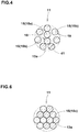
- the twisted cord 13a as the bead wire 11 is composed of a plurality of core filaments 15a, and a plurality of sheath filaments 15b which are twisted together. More specifically, the twisted cord 13a has a layer twist structure in which an outer layer 19 made up of the sheath filaments 15b are twisted around a core 18 made up of the core filaments 15a.
- the bead wire 11 having such layer twist structure exerts excellent bendability to increase the flexibility of the bead portion 4.
- the filaments 15 of the twisted cord 13a have a diameter d1 of from 0.15 to 0.45 mm. If the diameter d1 is less than 0.15 mm, there is a possibility that the binding force of the bead core 5 is decreased, and the steering/handling stability is adversely affected. If the diameter d1 is not less than 0.45 mm, there is a possibility that the flexibility of the bead portion 4 becomes insufficient, and the ride comfort performance is adversely affected.
- a contour 1a of the tire 1 in the ground contacting patch when the tire is normally loaded is indicated by an alternate long and two short dashes line.
- the bead portion 4 is bent toward the axially outside along the flange F of the wheel rim RM.
- the load acting on the bead seat B of the wheel rim RM becomes higher in the axially outer portion than in the axially inner portion.
- the first ring 13 is disposed as the axially outermost wire ring 10 in the bead core 5.
- the first ring 13 is axially outermost
- the second ring 14 is disposed axially inside the first ring 13.
- the first ring 13 having higher flexibility absorbs a large bending force, and the stress on the bead seat B is evened in the tire axial direction.
- the engaging force between bead portion of the tire 1 and the wheel rim RM becomes evened in the tire axial direction, and the steering/handling stability is improved.
- the number of the spiral turns of the bead wire 11 is not less than 1.5 times the number of the wire rings 10 in the bead core.
- the spiral turns of the bead wire 11 is counted from the radially innermost turn 11A toward the radially outermost turn 11C, some of the spiral turns more than 1.0 times the number of the wire rings 10 can generate a larger tension upon the inflation of the tire 1 and the application of a tire load, and the binding force of the bead core 5 is increased to improve the steering/handling stability.
- the number of the spiral turns is 8, and the number of the wire rings is 2.
- the radially outer end 5o of the bead core 5 is positioned radially inside the radially outer end Fo of the flange F, that is, the diameter R1 of the radially outer end 5o of the bead core 5 is less than the diameter R2 of the radially outer end Fo of the flange F.
- the tire is provided with moderate flexibility from the bead portion 4 to a lower sidewall portion, and the bead portion 4 becomes easy to bend along the rim flange F.
- the ride comfort performance is improved.
- Fig. 5 shows another example of the bead core 5 embedded in the bead portion 4 as another embodiment of the present invention, wherein the bead core 5 is composed of three wire rings 10 arranged in the tire axial direction.
- the three wire rings 10 are an axially outermost wire ring 10a, an axially innermost wire ring 10b, and a middle wire ring 10c therebetween.
- the outermost wire ring 10a is the above-mentioned first ring 13.
- the innermost wire ring 10b is the above-mentioned second ring 14.
- the middle wire ring 10c is the first ring 13 As explained above, as the first ring 13 is axially outermost in the bead core 5, the steering/handling stability is improved.
- the first ring 13 is disposed in a middle region of the bead seat B in which the middle wire ring 10c is disposed (the middle region is acted by a larger force than an inner region of the bead seat B in which the innermost wire ring 10b is disposed), the load acting on the middle wire ring 10c is absorbed by the first ring 13. Therefore, the variation of the stress on the bead seat B becomes small, and the engaging force between the bead portion of the tire 1 and the wheel rim RM becomes evened. As a result, the steering/handling stability is improved.
- the middle wire ring 10c is the second ring 14 and the innermost wire ring 10b is the first ring 13.
- the ride comfort performance during straight running becomes high in comparison with the example shown in Fig. 5 .
- the number of the first rings 13 is equal to or more than the number of the second ring(s) 14.
- the flexibility of the bead core 5 and the rigidity of the bead portion 4 are secured in good balance, and the steering/handling stability, ride comfort performance and uniformity is effectively improved.
- the number of the spiral turns of the bead wire 11 is not less than 1.5 times the number of the wire rings 10 in the bead core. In the example shown in Fig. 5 , the number of the spiral turns is 6, and the number of the wire rings 10 is 3. It is preferable that the radially outer end 5o of the bead core 5 is positioned radially inside the radially outer end Fo of the flange F.
- Fig. 6 shows a cord having a bunch twisted structure in which a plurality of filaments 15c constituting the cord are twisted all together in one direction.
- the cord having such a bunch twisted structure can be used as the low-cost twisted cord 13a.
- the bead core 5 can be manufactured, for example, by firstly manufacturing the wire rings 10 separately from each other by spirally winding the rubberized bead wire 11, and then closely arranging the wire rings 10 to be combined into the bead core 5.
- a tape of the bead wires 13a and 14a arranged side by side in the widthwise direction of the tape and rubberized is firstly manufactured, and then the tape is overlap wound into the bead core 5.
- the rubberized bead wire 11 or the tape of the bead wires is wound within an annular guide groove formed around an annular jig.
- the bead wires 13a and 14a arranged side by side without being united are wound within an annular guide groove into the bead core 5.
- motorcycle tires of size 180/55ZR17 were experimentally manufactured and tested for the ride comfort performance, handling stability and uniformity. Aside from the bead cores, all the test tires had the same structure. Specifications of the bead cores are shown in Table 1.
- the filaments constituting all the bead wires were steel filaments.
- the bending rigidity of the monofilament cord was 900 N.
- the elongation of the monofilament cord was 0.032 %.
- the carcass was composed of a single ply of nylon cords (2/1400 dtex, cord count 51/50 mm).
Landscapes
- Engineering & Computer Science (AREA)
- Mechanical Engineering (AREA)
- Tires In General (AREA)
- Ropes Or Cables (AREA)
Applications Claiming Priority (1)
| Application Number | Priority Date | Filing Date | Title |
|---|---|---|---|
| JP2016223472A JP6828390B2 (ja) | 2016-11-16 | 2016-11-16 | 空気入りタイヤ |
Publications (2)
| Publication Number | Publication Date |
|---|---|
| EP3323643A1 true EP3323643A1 (fr) | 2018-05-23 |
| EP3323643B1 EP3323643B1 (fr) | 2019-02-27 |
Family
ID=60327145
Family Applications (1)
| Application Number | Title | Priority Date | Filing Date |
|---|---|---|---|
| EP17201624.8A Active EP3323643B1 (fr) | 2016-11-16 | 2017-11-14 | Pneumatique |
Country Status (3)
| Country | Link |
|---|---|
| US (1) | US11077723B2 (fr) |
| EP (1) | EP3323643B1 (fr) |
| JP (1) | JP6828390B2 (fr) |
Citations (3)
| Publication number | Priority date | Publication date | Assignee | Title |
|---|---|---|---|---|
| US3942574A (en) * | 1974-12-16 | 1976-03-09 | The Goodyear Tire & Rubber Company | Tire bead |
| DE4137726A1 (de) * | 1990-11-16 | 1992-05-21 | Sumitomo Rubber Ind | Reifenwulst |
| WO2008061544A1 (fr) * | 2006-11-22 | 2008-05-29 | Pirelli Tyre S.P.A. | Pneu avec tringle légère |
Family Cites Families (17)
| Publication number | Priority date | Publication date | Assignee | Title |
|---|---|---|---|---|
| BE565709A (fr) * | 1957-03-14 | Michelin & Cie | ||
| US4823857A (en) * | 1988-03-16 | 1989-04-25 | The Goodyear Tire & Rubber Company | Tire beads |
| US5099902A (en) * | 1989-05-30 | 1992-03-31 | Bridgestone/Firestone, Inc. | Offset wound helical bead for pneumatic tires |
| JP3343293B2 (ja) * | 1994-08-08 | 2002-11-11 | 住友ゴム工業株式会社 | タイヤ用のスチールコード |
| JP2001097010A (ja) * | 1999-09-30 | 2001-04-10 | Bridgestone Corp | 空気入りタイヤ |
| EP1126074B1 (fr) * | 2000-02-17 | 2007-04-11 | Sumitomo Rubber Industries Limited | Pneumatique |
| JP4105397B2 (ja) * | 2000-03-02 | 2008-06-25 | 住友ゴム工業株式会社 | 金属コード及びそれを用いた空気入りタイヤ |
| WO2003037660A1 (fr) | 2001-10-30 | 2003-05-08 | Pirelli Pneumatici S.P.A. | Pneu a tringle comprenant un cable preforme |
| WO2006128494A1 (fr) * | 2005-05-30 | 2006-12-07 | Pirelli Tyre S.P.A. | Pneumatic tire with composite bead core |
| FR2956836B1 (fr) * | 2010-02-26 | 2015-03-27 | Michelin Soc Tech | Pneumatique ayant une plus grande resistance au decoincement. |
| JP5144783B2 (ja) * | 2011-04-08 | 2013-02-13 | 住友ゴム工業株式会社 | 空気入りタイヤ、及びその製造方法 |
| JP2013056566A (ja) * | 2011-09-07 | 2013-03-28 | Yokohama Rubber Co Ltd:The | 空気入りタイヤ |
| JP5416792B2 (ja) * | 2012-01-24 | 2014-02-12 | 住友ゴム工業株式会社 | 空気入りタイヤ |
| JP2013199236A (ja) * | 2012-03-26 | 2013-10-03 | Yokohama Rubber Co Ltd:The | 空気入りタイヤ |
| JP2015160599A (ja) * | 2014-02-28 | 2015-09-07 | 横浜ゴム株式会社 | 空気入りタイヤ |
| JP5946490B2 (ja) * | 2014-05-19 | 2016-07-06 | 住友ゴム工業株式会社 | 空気入りタイヤ |
| FR3030348B1 (fr) * | 2014-12-23 | 2017-06-23 | Michelin & Cie | Procede pour l'assemblage d'une ebauche de pneumatique |
-
2016
- 2016-11-16 JP JP2016223472A patent/JP6828390B2/ja active Active
-
2017
- 2017-11-14 EP EP17201624.8A patent/EP3323643B1/fr active Active
- 2017-11-15 US US15/813,587 patent/US11077723B2/en active Active
Patent Citations (3)
| Publication number | Priority date | Publication date | Assignee | Title |
|---|---|---|---|---|
| US3942574A (en) * | 1974-12-16 | 1976-03-09 | The Goodyear Tire & Rubber Company | Tire bead |
| DE4137726A1 (de) * | 1990-11-16 | 1992-05-21 | Sumitomo Rubber Ind | Reifenwulst |
| WO2008061544A1 (fr) * | 2006-11-22 | 2008-05-29 | Pirelli Tyre S.P.A. | Pneu avec tringle légère |
Also Published As
| Publication number | Publication date |
|---|---|
| JP6828390B2 (ja) | 2021-02-10 |
| US20180134099A1 (en) | 2018-05-17 |
| US11077723B2 (en) | 2021-08-03 |
| JP2018079801A (ja) | 2018-05-24 |
| EP3323643B1 (fr) | 2019-02-27 |
Similar Documents
| Publication | Publication Date | Title |
|---|---|---|
| US10589577B2 (en) | Heavy-duty pneumatic tire | |
| US6609552B2 (en) | Pneumatic tire with single-twist organic filter band cords | |
| EP2607104B1 (fr) | Pneu | |
| EP2246201B1 (fr) | Pneu à carcasse radiale | |
| CN115362071B (zh) | 充气轮胎 | |
| KR20130086306A (ko) | 공기 타이어 | |
| JP2019142395A (ja) | 空気入りタイヤ | |
| US20150000817A1 (en) | Pneumatic tire for two-wheeled motor vehicle | |
| EP3059100B1 (fr) | Pneu | |
| JP5358333B2 (ja) | 空気入りタイヤ | |
| EP3323643B1 (fr) | Pneumatique | |
| JP2008179325A (ja) | 空気入りラジアルタイヤ | |
| CN115335239B (zh) | 充气轮胎 | |
| US20230241922A1 (en) | Pneumatic tire | |
| EP3287302B1 (fr) | Pneumatique | |
| US20220016933A1 (en) | Tire | |
| EP4257371A1 (fr) | Pneumatique | |
| CN111070970B (zh) | 轮胎 | |
| US20220305850A1 (en) | Pneumatic tire | |
| JP2019142352A (ja) | 空気入りタイヤ | |
| JP2010012828A (ja) | 空気入りタイヤ | |
| JP2017196954A (ja) | 空気入りタイヤ | |
| JP2008290503A (ja) | 空気入りラジアルタイヤ | |
| CN117881552A (zh) | 充气轮胎 | |
| JP2023064380A (ja) | 空気入りタイヤ |
Legal Events
| Date | Code | Title | Description |
|---|---|---|---|
| PUAI | Public reference made under article 153(3) epc to a published international application that has entered the european phase |
Free format text: ORIGINAL CODE: 0009012 |
|
| STAA | Information on the status of an ep patent application or granted ep patent |
Free format text: STATUS: THE APPLICATION HAS BEEN PUBLISHED |
|
| AK | Designated contracting states |
Kind code of ref document: A1 Designated state(s): AL AT BE BG CH CY CZ DE DK EE ES FI FR GB GR HR HU IE IS IT LI LT LU LV MC MK MT NL NO PL PT RO RS SE SI SK SM TR |
|
| AX | Request for extension of the european patent |
Extension state: BA ME |
|
| STAA | Information on the status of an ep patent application or granted ep patent |
Free format text: STATUS: REQUEST FOR EXAMINATION WAS MADE |
|
| 17P | Request for examination filed |
Effective date: 20180731 |
|
| RBV | Designated contracting states (corrected) |
Designated state(s): AL AT BE BG CH CY CZ DE DK EE ES FI FR GB GR HR HU IE IS IT LI LT LU LV MC MK MT NL NO PL PT RO RS SE SI SK SM TR |
|
| REG | Reference to a national code |
Ref country code: DE Ref legal event code: R079 Ref document number: 602017002378 Country of ref document: DE Free format text: PREVIOUS MAIN CLASS: B60C0015040000 Ipc: B60C0015000000 |
|
| RIC1 | Information provided on ipc code assigned before grant |
Ipc: B60C 15/04 20060101ALI20180905BHEP Ipc: B60C 15/00 20060101AFI20180905BHEP Ipc: B60C 15/05 20060101ALI20180905BHEP Ipc: B29D 30/48 20060101ALI20180905BHEP |
|
| GRAP | Despatch of communication of intention to grant a patent |
Free format text: ORIGINAL CODE: EPIDOSNIGR1 |
|
| STAA | Information on the status of an ep patent application or granted ep patent |
Free format text: STATUS: GRANT OF PATENT IS INTENDED |
|
| INTG | Intention to grant announced |
Effective date: 20181030 |
|
| GRAS | Grant fee paid |
Free format text: ORIGINAL CODE: EPIDOSNIGR3 |
|
| GRAA | (expected) grant |
Free format text: ORIGINAL CODE: 0009210 |
|
| STAA | Information on the status of an ep patent application or granted ep patent |
Free format text: STATUS: THE PATENT HAS BEEN GRANTED |
|
| AK | Designated contracting states |
Kind code of ref document: B1 Designated state(s): AL AT BE BG CH CY CZ DE DK EE ES FI FR GB GR HR HU IE IS IT LI LT LU LV MC MK MT NL NO PL PT RO RS SE SI SK SM TR |
|
| REG | Reference to a national code |
Ref country code: GB Ref legal event code: FG4D |
|
| REG | Reference to a national code |
Ref country code: CH Ref legal event code: EP |
|
| REG | Reference to a national code |
Ref country code: AT Ref legal event code: REF Ref document number: 1100786 Country of ref document: AT Kind code of ref document: T Effective date: 20190315 |
|
| REG | Reference to a national code |
Ref country code: IE Ref legal event code: FG4D |
|
| REG | Reference to a national code |
Ref country code: DE Ref legal event code: R096 Ref document number: 602017002378 Country of ref document: DE |
|
| REG | Reference to a national code |
Ref country code: NL Ref legal event code: MP Effective date: 20190227 |
|
| REG | Reference to a national code |
Ref country code: LT Ref legal event code: MG4D |
|
| PG25 | Lapsed in a contracting state [announced via postgrant information from national office to epo] |
Ref country code: NO Free format text: LAPSE BECAUSE OF FAILURE TO SUBMIT A TRANSLATION OF THE DESCRIPTION OR TO PAY THE FEE WITHIN THE PRESCRIBED TIME-LIMIT Effective date: 20190527 Ref country code: PT Free format text: LAPSE BECAUSE OF FAILURE TO SUBMIT A TRANSLATION OF THE DESCRIPTION OR TO PAY THE FEE WITHIN THE PRESCRIBED TIME-LIMIT Effective date: 20190627 Ref country code: FI Free format text: LAPSE BECAUSE OF FAILURE TO SUBMIT A TRANSLATION OF THE DESCRIPTION OR TO PAY THE FEE WITHIN THE PRESCRIBED TIME-LIMIT Effective date: 20190227 Ref country code: NL Free format text: LAPSE BECAUSE OF FAILURE TO SUBMIT A TRANSLATION OF THE DESCRIPTION OR TO PAY THE FEE WITHIN THE PRESCRIBED TIME-LIMIT Effective date: 20190227 Ref country code: SE Free format text: LAPSE BECAUSE OF FAILURE TO SUBMIT A TRANSLATION OF THE DESCRIPTION OR TO PAY THE FEE WITHIN THE PRESCRIBED TIME-LIMIT Effective date: 20190227 Ref country code: LT Free format text: LAPSE BECAUSE OF FAILURE TO SUBMIT A TRANSLATION OF THE DESCRIPTION OR TO PAY THE FEE WITHIN THE PRESCRIBED TIME-LIMIT Effective date: 20190227 |
|
| PG25 | Lapsed in a contracting state [announced via postgrant information from national office to epo] |
Ref country code: BG Free format text: LAPSE BECAUSE OF FAILURE TO SUBMIT A TRANSLATION OF THE DESCRIPTION OR TO PAY THE FEE WITHIN THE PRESCRIBED TIME-LIMIT Effective date: 20190527 Ref country code: LV Free format text: LAPSE BECAUSE OF FAILURE TO SUBMIT A TRANSLATION OF THE DESCRIPTION OR TO PAY THE FEE WITHIN THE PRESCRIBED TIME-LIMIT Effective date: 20190227 Ref country code: RS Free format text: LAPSE BECAUSE OF FAILURE TO SUBMIT A TRANSLATION OF THE DESCRIPTION OR TO PAY THE FEE WITHIN THE PRESCRIBED TIME-LIMIT Effective date: 20190227 Ref country code: IS Free format text: LAPSE BECAUSE OF FAILURE TO SUBMIT A TRANSLATION OF THE DESCRIPTION OR TO PAY THE FEE WITHIN THE PRESCRIBED TIME-LIMIT Effective date: 20190627 Ref country code: GR Free format text: LAPSE BECAUSE OF FAILURE TO SUBMIT A TRANSLATION OF THE DESCRIPTION OR TO PAY THE FEE WITHIN THE PRESCRIBED TIME-LIMIT Effective date: 20190528 Ref country code: HR Free format text: LAPSE BECAUSE OF FAILURE TO SUBMIT A TRANSLATION OF THE DESCRIPTION OR TO PAY THE FEE WITHIN THE PRESCRIBED TIME-LIMIT Effective date: 20190227 |
|
| REG | Reference to a national code |
Ref country code: AT Ref legal event code: MK05 Ref document number: 1100786 Country of ref document: AT Kind code of ref document: T Effective date: 20190227 |
|
| PG25 | Lapsed in a contracting state [announced via postgrant information from national office to epo] |
Ref country code: DK Free format text: LAPSE BECAUSE OF FAILURE TO SUBMIT A TRANSLATION OF THE DESCRIPTION OR TO PAY THE FEE WITHIN THE PRESCRIBED TIME-LIMIT Effective date: 20190227 Ref country code: EE Free format text: LAPSE BECAUSE OF FAILURE TO SUBMIT A TRANSLATION OF THE DESCRIPTION OR TO PAY THE FEE WITHIN THE PRESCRIBED TIME-LIMIT Effective date: 20190227 Ref country code: ES Free format text: LAPSE BECAUSE OF FAILURE TO SUBMIT A TRANSLATION OF THE DESCRIPTION OR TO PAY THE FEE WITHIN THE PRESCRIBED TIME-LIMIT Effective date: 20190227 Ref country code: CZ Free format text: LAPSE BECAUSE OF FAILURE TO SUBMIT A TRANSLATION OF THE DESCRIPTION OR TO PAY THE FEE WITHIN THE PRESCRIBED TIME-LIMIT Effective date: 20190227 Ref country code: RO Free format text: LAPSE BECAUSE OF FAILURE TO SUBMIT A TRANSLATION OF THE DESCRIPTION OR TO PAY THE FEE WITHIN THE PRESCRIBED TIME-LIMIT Effective date: 20190227 Ref country code: IT Free format text: LAPSE BECAUSE OF FAILURE TO SUBMIT A TRANSLATION OF THE DESCRIPTION OR TO PAY THE FEE WITHIN THE PRESCRIBED TIME-LIMIT Effective date: 20190227 Ref country code: SK Free format text: LAPSE BECAUSE OF FAILURE TO SUBMIT A TRANSLATION OF THE DESCRIPTION OR TO PAY THE FEE WITHIN THE PRESCRIBED TIME-LIMIT Effective date: 20190227 Ref country code: AL Free format text: LAPSE BECAUSE OF FAILURE TO SUBMIT A TRANSLATION OF THE DESCRIPTION OR TO PAY THE FEE WITHIN THE PRESCRIBED TIME-LIMIT Effective date: 20190227 |
|
| REG | Reference to a national code |
Ref country code: DE Ref legal event code: R097 Ref document number: 602017002378 Country of ref document: DE |
|
| PG25 | Lapsed in a contracting state [announced via postgrant information from national office to epo] |
Ref country code: PL Free format text: LAPSE BECAUSE OF FAILURE TO SUBMIT A TRANSLATION OF THE DESCRIPTION OR TO PAY THE FEE WITHIN THE PRESCRIBED TIME-LIMIT Effective date: 20190227 Ref country code: SM Free format text: LAPSE BECAUSE OF FAILURE TO SUBMIT A TRANSLATION OF THE DESCRIPTION OR TO PAY THE FEE WITHIN THE PRESCRIBED TIME-LIMIT Effective date: 20190227 |
|
| PG25 | Lapsed in a contracting state [announced via postgrant information from national office to epo] |
Ref country code: AT Free format text: LAPSE BECAUSE OF FAILURE TO SUBMIT A TRANSLATION OF THE DESCRIPTION OR TO PAY THE FEE WITHIN THE PRESCRIBED TIME-LIMIT Effective date: 20190227 |
|
| PLBE | No opposition filed within time limit |
Free format text: ORIGINAL CODE: 0009261 |
|
| STAA | Information on the status of an ep patent application or granted ep patent |
Free format text: STATUS: NO OPPOSITION FILED WITHIN TIME LIMIT |
|
| 26N | No opposition filed |
Effective date: 20191128 |
|
| PG25 | Lapsed in a contracting state [announced via postgrant information from national office to epo] |
Ref country code: TR Free format text: LAPSE BECAUSE OF FAILURE TO SUBMIT A TRANSLATION OF THE DESCRIPTION OR TO PAY THE FEE WITHIN THE PRESCRIBED TIME-LIMIT Effective date: 20190227 |
|
| PG25 | Lapsed in a contracting state [announced via postgrant information from national office to epo] |
Ref country code: MC Free format text: LAPSE BECAUSE OF FAILURE TO SUBMIT A TRANSLATION OF THE DESCRIPTION OR TO PAY THE FEE WITHIN THE PRESCRIBED TIME-LIMIT Effective date: 20190227 Ref country code: LU Free format text: LAPSE BECAUSE OF NON-PAYMENT OF DUE FEES Effective date: 20191114 |
|
| REG | Reference to a national code |
Ref country code: BE Ref legal event code: MM Effective date: 20191130 |
|
| PG25 | Lapsed in a contracting state [announced via postgrant information from national office to epo] |
Ref country code: IE Free format text: LAPSE BECAUSE OF NON-PAYMENT OF DUE FEES Effective date: 20191114 |
|
| PG25 | Lapsed in a contracting state [announced via postgrant information from national office to epo] |
Ref country code: BE Free format text: LAPSE BECAUSE OF NON-PAYMENT OF DUE FEES Effective date: 20191130 |
|
| PG25 | Lapsed in a contracting state [announced via postgrant information from national office to epo] |
Ref country code: CY Free format text: LAPSE BECAUSE OF FAILURE TO SUBMIT A TRANSLATION OF THE DESCRIPTION OR TO PAY THE FEE WITHIN THE PRESCRIBED TIME-LIMIT Effective date: 20190227 |
|
| REG | Reference to a national code |
Ref country code: CH Ref legal event code: PL |
|
| PG25 | Lapsed in a contracting state [announced via postgrant information from national office to epo] |
Ref country code: HU Free format text: LAPSE BECAUSE OF FAILURE TO SUBMIT A TRANSLATION OF THE DESCRIPTION OR TO PAY THE FEE WITHIN THE PRESCRIBED TIME-LIMIT; INVALID AB INITIO Effective date: 20171114 Ref country code: MT Free format text: LAPSE BECAUSE OF FAILURE TO SUBMIT A TRANSLATION OF THE DESCRIPTION OR TO PAY THE FEE WITHIN THE PRESCRIBED TIME-LIMIT Effective date: 20190227 |
|
| PG25 | Lapsed in a contracting state [announced via postgrant information from national office to epo] |
Ref country code: LI Free format text: LAPSE BECAUSE OF NON-PAYMENT OF DUE FEES Effective date: 20201130 Ref country code: CH Free format text: LAPSE BECAUSE OF NON-PAYMENT OF DUE FEES Effective date: 20201130 |
|
| PG25 | Lapsed in a contracting state [announced via postgrant information from national office to epo] |
Ref country code: SI Free format text: LAPSE BECAUSE OF FAILURE TO SUBMIT A TRANSLATION OF THE DESCRIPTION OR TO PAY THE FEE WITHIN THE PRESCRIBED TIME-LIMIT Effective date: 20190227 |
|
| PG25 | Lapsed in a contracting state [announced via postgrant information from national office to epo] |
Ref country code: MK Free format text: LAPSE BECAUSE OF FAILURE TO SUBMIT A TRANSLATION OF THE DESCRIPTION OR TO PAY THE FEE WITHIN THE PRESCRIBED TIME-LIMIT Effective date: 20190227 |
|
| GBPC | Gb: european patent ceased through non-payment of renewal fee |
Effective date: 20211114 |
|
| PG25 | Lapsed in a contracting state [announced via postgrant information from national office to epo] |
Ref country code: GB Free format text: LAPSE BECAUSE OF NON-PAYMENT OF DUE FEES Effective date: 20211114 |
|
| P01 | Opt-out of the competence of the unified patent court (upc) registered |
Effective date: 20230510 |
|
| PGFP | Annual fee paid to national office [announced via postgrant information from national office to epo] |
Ref country code: FR Payment date: 20230929 Year of fee payment: 7 |
|
| PGFP | Annual fee paid to national office [announced via postgrant information from national office to epo] |
Ref country code: DE Payment date: 20230929 Year of fee payment: 7 |