EP3323260B1 - Système et procédé de programmation dynamique d'émissions radioélectriques sans collision - Google Patents
Système et procédé de programmation dynamique d'émissions radioélectriques sans collision Download PDFInfo
- Publication number
- EP3323260B1 EP3323260B1 EP16825065.2A EP16825065A EP3323260B1 EP 3323260 B1 EP3323260 B1 EP 3323260B1 EP 16825065 A EP16825065 A EP 16825065A EP 3323260 B1 EP3323260 B1 EP 3323260B1
- Authority
- EP
- European Patent Office
- Prior art keywords
- time slot
- time
- master
- mark
- tag
- Prior art date
- Legal status (The legal status is an assumption and is not a legal conclusion. Google has not performed a legal analysis and makes no representation as to the accuracy of the status listed.)
- Active
Links
- 230000005540 biological transmission Effects 0.000 title claims description 133
- 238000000034 method Methods 0.000 title claims description 55
- 230000004044 response Effects 0.000 claims description 5
- 230000007958 sleep Effects 0.000 description 10
- 238000004891 communication Methods 0.000 description 4
- 238000012546 transfer Methods 0.000 description 4
- 239000000203 mixture Substances 0.000 description 2
- 230000008569 process Effects 0.000 description 2
- 101100368725 Bacillus subtilis (strain 168) tagF gene Proteins 0.000 description 1
- 230000001413 cellular effect Effects 0.000 description 1
- 230000001010 compromised effect Effects 0.000 description 1
- 230000008878 coupling Effects 0.000 description 1
- 238000010168 coupling process Methods 0.000 description 1
- 238000005859 coupling reaction Methods 0.000 description 1
- 125000004122 cyclic group Chemical group 0.000 description 1
- 238000013461 design Methods 0.000 description 1
- 238000011161 development Methods 0.000 description 1
- 238000011156 evaluation Methods 0.000 description 1
- 238000005259 measurement Methods 0.000 description 1
- 230000007246 mechanism Effects 0.000 description 1
- 238000012545 processing Methods 0.000 description 1
- 230000011664 signaling Effects 0.000 description 1
- 238000012360 testing method Methods 0.000 description 1
Images


Classifications
-
- H—ELECTRICITY
- H04—ELECTRIC COMMUNICATION TECHNIQUE
- H04W—WIRELESS COMMUNICATION NETWORKS
- H04W74/00—Wireless channel access, e.g. scheduled or random access
- H04W74/04—Scheduled or contention-free access
-
- H—ELECTRICITY
- H04—ELECTRIC COMMUNICATION TECHNIQUE
- H04W—WIRELESS COMMUNICATION NETWORKS
- H04W72/00—Local resource management
- H04W72/04—Wireless resource allocation
- H04W72/044—Wireless resource allocation based on the type of the allocated resource
- H04W72/0446—Resources in time domain, e.g. slots or frames
-
- H—ELECTRICITY
- H04—ELECTRIC COMMUNICATION TECHNIQUE
- H04W—WIRELESS COMMUNICATION NETWORKS
- H04W84/00—Network topologies
- H04W84/18—Self-organising networks, e.g. ad-hoc networks or sensor networks
- H04W84/20—Master-slave selection or change arrangements
Definitions
- Radio-frequency (RF) tracking is used in many different types of sporting events and for a variety of purposes.
- RF tags may be attached to players and balls to track their respective movements.
- each RF tag is in RF communication with multiple receivers at different respective locations to determine the position of each RF tag. It is also commonplace to equip runners in a race with RF tags for finish line timing, and in some cases for tracking the progress of the runners during the race.
- RF tracking is also utilized to transmit biometric data of an athlete, such as an athlete's heart rate, by coupling an RF tag with a biometric measurement device carried by the athlete.
- the RF tag attached to the object to be tracked emits a radio signal that is detected by one or more receivers.
- the ping rate i.e., periodicity, frequency or rate of transmission
- the ping rate may require between ten and one hundred locates per second.
- many tags may be configured to transmit frequently, typically resulting in overlap of transmission. This is particularly challenging in events like football where a large number of fast moving objects are tracked to continuously provide position information for each athlete and the ball. In many cases, the quality of location determination is compromised by transmission overlap, often resulting in failure to locate one or more objects.
- Document WO 2010/073158 A1 describes a system for scheduling wireless transmissions using a flexible superframe to be repeated.
- the superframe is divided into a beacon period, a data/sense/sleep period, and a signaling window, each having different numbers of time slots.
- Document WO 2010/018523 A2 also describes a system for scheduling wireless transmissions using superframe.
- the superframe is constituded of subframes, and different superframes include subframes of different lengths.
- document US 8 248 981 B2 describes a system for wireless transmission.
- a system dynamically schedules wireless transmissions without collision within a repeating frame.
- Each frame is divided into a plurality of consecutive blocks and each block is divided into a plurality of consecutive time slots.
- a first predefined time slot in each block is used for announcement transmissions.
- the system includes a master transmitter capable of transmitting a master time mark during a second predefined time slot in each block.
- the master time mark includes a time slot reservation area for indicating dynamic allocation of time slots.
- the system also includes a processor communicatively coupled with the master transmitter, a non-transitory memory communicatively coupled with the processor, a time slot reservation table stored within the memory for tracking the predefined time slots and dynamic allocation of the time slots within each block, and an allocator, implemented as machine readable instructions stored in the memory and executed by the processor, capable of: allocating, based upon the time slot reservation table, at least one unallocated time slot in at least one of the plurality of blocks for use by a transmitting device in response to an announcement message received from the transmitting device during the first predefined time slot; and updating the time slot reservation area and the time slot reservation table to indicate the allocation of the at least one time slot to the transmitting device.
- the transmitting device receives a subsequent master time mark and transmits only during the indicated at least one time slot of a subsequent frame.
- a method dynamically schedules wireless transmissions without collision.
- a master transmitter periodically transmits a time mark during a first predefined time slot of a plurality of consecutive time slots that form a transmission block. Multiple consecutive transmission blocks form a frame.
- An announcement transmission from a wireless transmitting device is received via at least one receiver during a second predefined time slot of the plurality of time slots.
- An allocator allocates, at least partly based upon the received announcement transmission, a third time slot of the plurality of time slots to the wireless transmitting device.
- a time slot reservation area of at least one subsequently transmitted time mark includes indication of the allocation of the third time slot to the wireless transmitting device.
- the wireless transmitting device receives the subsequently transmitted time mark and transmits only during the third time slot of subsequent frames.
- This document describes example systems and methods for dynamically scheduling transmissions from a plurality of wireless tags.
- the wireless tag transmissions are used to track objects within an operational area using ranging techniques.
- the disclosed dynamic scheduling systems and methods may be used for other purposes, such as data transfer, without departing from the scope hereof.
- the primary characteristics of the disclosed systems and methods are a global clocking scheme that creates defined time slots that are used for slotted transmissions that favor high and adjustable transmission rates, with dynamic and automatic registration and configuration of the wireless tags.
- the advantages of the disclosed systems and methods are that transmission collisions are avoided by dynamically assigning one or more of the time slots for use by each transmitting device such that only one device is transmitting at any one time.
- FIG. 1 shows one example system 100 for dynamically scheduling wireless transmissions.
- System 100 operates to track objects (participants, officials, balls, equipment, etc.) at a sporting event, for example.
- System 100 includes a plurality of wireless tags 102 located within an operational area 150 (e.g., each tag 102 may be attached to an object to be tracked), at least one receiver 104 (also known as sensors and anchors), a master transmitter 106, optionally one or two slave transmitters 108, and a computer 110.
- System 100 may use more or fewer tags 102 and/or receivers 104 without departing from the scope hereof.
- System 100 receives transmissions from tags 102 when tags 102 are within an operational area 150.
- the operational area 150 may include a performance area 152, such as an American football field, a race track, or similar sporting arenas.
- system 100 is shown with four receivers 104(1)-(4) positioned around operational area 150 and communicatively coupled, via a network 120, with computer 110.
- Network 120 is for example based upon one or more of Ethernet, Wi-Fi, UWB, cellular and USB. Transmissions from wireless tags 102 are received by one or more of receivers 104 and information and data of those received transmissions are sent to computer 110 via a network 120.
- Computer 110 includes one or more processors 115, memory 111, and an allocator 112.
- the allocator 112 may be implemented as software having machine readable instructions stored within memory 111 and executed by processor 115 to configure tags 102, receivers 104, and transmitters 106, 108 of system 100 for operation, as described in detail below.
- wireless tags 102, receivers 104, and transmitters 106, 108 operate within the ultra-wide-band (UWB) frequency range using conventional UWB protocols, where each tag 102, receiver 104, and transmitters 106, 108 is configured with, for example, at least one DW1000 chip from DecaWave Ltd.
- the DW1000 is a fully integrated single chip UWB low-power low-cost transceiver IC compliant to IEEE802.15.4-2011.
- wireless tags 102, receivers 104, and transmitters 106, 108 may operate at other frequencies, use other protocols, and use other chips without departing from the scope hereof.
- timing is based upon the duration of each transmission from wireless tags 102.
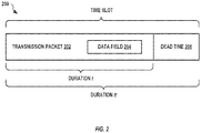
- FIG. 2 shows one example time slot 200 that has a duration tt that is longer than the duration t of a transmission packet 202. That is, the duration of time slot 200 is long enough to include transmission packet 202 and a dead time 206, which is a period where no transmission is desired and is included to prevent transmission collision that might occur if a local clock of a wireless tag 102 transmitting in a first time slot drifts relative to a local clock of another wireless tag 102 transmitting in an adjacent time slot 200.
- time slot 200 has a period of 132 ⁇ s, giving a total of about 7,600 time slots per second.
- transmission packet 202 includes a data field 204, however, transmission packet 202 may have other formats without departing from the scope hereof.
- shortest duration t of transmission packet 202 is 120 ⁇ s.
- System 100 dynamically controls transmission time (also known as air time) of transmitting devices (e.g., wireless tags 102, transmitter 106, 108) according to time slots 200.
- the number of consecutive time slots 200 allocated for any particular transmission defines a maximum packet size that may be transmitted. That is, allocator 112 may allocate multiple time slots 200 to any transmitting device to allow for transmissions requiring a duration greater than a single time slot 200.
- FIG. 3 shows one example transmission block 300 that has a duration tb that includes one-hundred and twenty-eight consecutive time slots 200, consecutively numbered 0 through 127.
- duration tb is about 16.9 ms, and consecutive transmission blocks 300 therefore repeat at a frequency of about 59 Hz.
- other block durations, and thus the number of time slots 200 contained therein, may be used without departing from the scope hereof.
- each transmission block 300 is signaled by a master time mark 302 that is transmitted by master transmitter 106, and optionally followed by one or both of a slave time mark 304(1), transmitted by slave transmitter 108(1), and a slave time mark 304(2), transmitted by slave transmitter 108(2).
- each time mark 302, 304 is allocated two time slots 200; specifically, time slots 0 and 1 are dedicated for use by master time mark 302, time slots 2 and 3 are dedicated for use by slave time mark 304(1), and time slots 4 and 5 are dedicated for use by slave time mark 304(2).
- the number of time slots allocated for use by time marks 302, 304 is based upon the amount of data to be included within each time mark.
- Time slot 127 is dedicated for announcement 308 transmission by tags 102, where any tag 102 that is not yet configured may transmit an announcement 308 within time slot 127 to announce its presence to system 100.
- Allocator 112 dynamically allocates time slots 6 through 126 for use by tags 102 and optionally by receivers 104. Allocator 112 maintains a time slot reservation table 114 within memory of computer 110 that defines which time slots 200 of each transmission block 300 are allocated for use by each transmitting device (e.g., tags 102 and optionally receivers 104, and transmitters 106, 108).
- each transmitting device e.g., tags 102 and optionally receivers 104, and transmitters 106, 108.
- FIG. 4 shows one example transmission frame 400 with a duration tf that includes sixty-four consecutive transmission blocks 300. Continuing with the above example, duration tf of each transmission frame 400 is just over one second.
- transmissions use the format defined in transmission packet 202 of FIG. 2 , where data field 204 includes at least the following data items: Data Item Name Description packet type defines the kind of packet being sent. sender node ID gives the sender's node ID or 0x00 if unassigned.
- sender node ID is one byte, and thus operation of system 100 may include up to 255 different transmitting devices (e.g., tags 102, receivers 104, and transmitters 106, 108).
- system 100 The operation of system 100 is described from the point of view of the participating devices. At first, operation is assumed to be with a separate backhaul network (i.e., using network 120) for transferring data from receivers 104 to computer 110. Later, using the UWB as backhaul will be discussed, wherein data sent from receivers 104 to computer 110 are transmitted wirelessly and share the bandwidth provided by allocation of time slots 200.
- a separate backhaul network i.e., using network 120
- UWB as backhaul will be discussed, wherein data sent from receivers 104 to computer 110 are transmitted wirelessly and share the bandwidth provided by allocation of time slots 200.
- Master transmitter 106 contains a very stable clock and transmits master time mark 302 at the start of each transmission block 300 to provide global timing to system 100. Only one master transmitter 106 is used within system 100 and is positioned to maximize the number of other devices 102, 104, 108 that receive its transmission (i.e., master time mark 302). Master transmitter 106 is assumed to have adequate amounts of power to receive and transmit as needed.
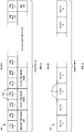
- FIG. 5 shows one example data field 204 of master time mark 302.
- master time mark 302 includes a time slot counter 502, a time slot reservations area 504, and an auxiliary command area 506.
- Time slot counter 502 is an integer value that is initialized to zero and incremented by the number of time slots 200 within each transmission block 300 (e.g., 128) for each new transmission of master time mark 302.
- time slot counter 502 thereby identifies the time slot 200 of the current transmission.
- slot counter 502 is implemented as a 32 bit number, and therefore does not wrap around for 156 hours (6.5 days) of continuous operation.
- Auxiliary command area 506 is an optional command and argument area that allows control commands and data to be included within master time mark 302 and thus receives by any receiving device (e.g., tags 102, receivers 104, and slave transmitters 108).
- FIG. 6 shows time slot reservations area 504 of FIG. 5 in further example detail.
- Time slot reservations area 504 contains an array of time slot allocations 601, where each time slot allocation 601 includes a node ID 602, a time slot value 604, an interval value 606, a phase value 608, and a time mark phase value 610.
- Node ID 602 identifies the transmitter (e.g., a tag 102) to which the reservation applies, and time slot value 604 identifies one time slot 200 within transmission block 300 (e.g., a value from 6 to 126).
- time slot reservations area 504 includes four time slot allocations 601, where a first master time mark 302 includes time slot allocations 601 for a first four different wireless tags 102, a subsequent master time mark 302 includes time slot allocations 601 for a next different set of four wireless tags, and so on, repeating in a cyclic manner.
- Use of interval value 606, phase value 608, and time mark phase value 610 is described in detail below.
- FIG. 10 is a schematic illustrating example distribution of time slot allocations 601 within transmission frame 400, where each block may include time slot allocations 601 for four different wireless tags 102.
- time slot allocations 601 may be included for different transmitting nodes (e.g., tags 102 and receivers 104).
- tags 102 and receivers 104 may be allocated dynamically as tags 102 announce themselves to system 100, and may therefore not be in sequence.
- master transmitter 106 emits master time mark 302 precisely at a period of transmission block 300 until system 100 is shut down.
- slave transmitters 108(1) and 108(2) may be included to extend operation of system 100 beyond the transmission range of master transmitter 106.
- Slave transmitters 108(1) and 108(2) transmit slave time mark 304(1) and 304(2), respectively, and may be positioned such that all devices (e.g., tags 102 and receivers 104) of system 100 within operational area 150 are able to receive at least one of master time mark 302 and slave time marks 304(1) and 104(2).
- each slave transmitter 108 is substantially identical to master transmitter 106, and is positioned such that (a) it is in range to receive master time mark 302, and (b) a sufficient number of receivers 104 are able to receive both slave time mark 304 and master time mark 302.
- Each included slave transmitter 108 is configured via network 120 and receives its unique node ID, which defines which time slots 200 it transmits within, in each transmission block 300, as shown in FIG. 3 (i.e., if assigned as the first slave transmitter, it transmits within time slots 2 and 3, otherwise it transmits in time slots 4 and 5).
- each included slave transmitter 108 transmits slave time mark 304 containing its node ID, an adjusted slot counter (i.e., slave transmitter 108(1) sends master time mark 302 slot counter + 2, and slave transmitter 108(2) sends master time mark 302 slot counter + 4) and the same information as time slot reservations area 504 and auxiliary command area 506 as in master time mark 302.
- an adjusted slot counter i.e., slave transmitter 108(1) sends master time mark 302 slot counter + 2
- slave transmitter 108(2) sends master time mark 302 slot counter + 4
- each slave transmitter 108 synchronizes with master transmitter 106 by receiving master time mark 302 to determine parameters for converting global time to their local clock and thereby align itself with its allocated time slot. If slave transmitter 108 does not receive master time mark 302, it may receive transmissions from one or more other nodes (e.g., tags 102 and other transmitter 108) and align itself with its allocated time slot 200 based upon information of time slot reservation table 114. Via network 120, slave transmitter 108 may receive information as to how to adjust its local clock to be more aligned with master transmitter 106.
- master time mark 302 may receive transmissions from one or more other nodes (e.g., tags 102 and other transmitter 108) and align itself with its allocated time slot 200 based upon information of time slot reservation table 114.
- slave transmitter 108 may receive information as to how to adjust its local clock to be more aligned with master transmitter 106.
- At least one receiver 104 may determine an alignment error between slave time mark 304 and master time mark 302 and provide an adjustment to slave transmitter 108 via network 120.
- Each receiver 104 is positioned such that transmissions from tags 102 within operational area 150 are received.
- Each receiver 104 is connected to computer 110 via network 120 and has a stable clock.
- Each receiver 104 is able to receive at least one of master time mark 302 and slave time mark 304, and thereby synchronizes itself for operation within system 100. Operation of receiver 104 assumes adequate amounts of power to receive and transmit as needed.
- receiver 104 receives all transmissions, records data received within transmission and at least a timestamp indicative of the time the transmission was received, and optionally one or more of signal strength, signal quality, and so on. Receiver 104 then sends this information via network 120 to computer 110.
- Tags 102 are attached to objects, such as people, athletes, balls, and so on, that are to be tracked within operational area 150.
- Tags 102 utilize power from at least one battery and therefore system 100 operates to configure each tag 102 with a desired ping rate such that each tag 102 transmits only as often as necessary, thereby reducing power consumption and the size of the battery needed to power the tag 102.
- tag 102 configures itself in a low-power mode (also known as sleep mode) when not required to transmit, receive, or perform other operations.
- a low-power mode also known as sleep mode
- tag 102 configures itself to periodically wake, at a low duty cycle, to receive master time mark 302 or slave time mark 304.
- tag 102 awakens and activates its receiver to "listen" for a period greater than duration tb of one transmission block 300 once every minute, and thereby has a very low duty cycle (e.g., about 0.03%).
- the sleep interval between listening periods may be varied to aid in randomizing tag wake up times, thereby reducing likelihood of repeating transmission collisions where two tags awaken at the same time to request configuration.
- tag 102 Since tag 102 is listening for a period greater than the duration of one transmission block 300, it is assured of receiving master time mark 302 and/or slave time mark 304 when in range of an operational system 100. When tag 102 does not receive a master time make (or slave time mark) it assumes that it is not within range of operational system 100 and returns to its low-power mode.
- time slot 127 of each transmission block 300 is reserved for announcements 308 from tags 102 that are not yet configured by system 100. Since there are likely to be few unconfigured tags 102 during operation of system 100, and since time slot 127 precedes time slot 0 of a subsequent transmission block 300, time slot 127 is typically transmission free prior to transmission of master time mark 302 during operation.
- tag 102 determines a current slot counter of the received transmission. It may also determine whether the received transmission was from master transmitter 106 or a slave transmitter 108 using either the received node ID or the received slot counter 502.
- Tag 102 then computes a start time for time slot 127 of the current transmission block 300 and transmits announcement 308 within time slot 127 to identify itself to system 100, where tag announce 308 packet contains a long serial number or MAC address that uniquely identifies tag 102.
- announcement 308 also includes other parameters from tag 102 (e.g., battery level, and so on). Announcement 308 is limited in length to duration dt of a single time slot 200.
- tag 102 After sending announcement 308, tag 102 configures itself to awaken from a low-power mode to receive master time mark 302 in a transmission block 300 that is several (e.g., sixteen) blocks into the future, wherein allocator 112 inserts time slot reservation information within that block.
- This block delay (e.g., sixteen blocks) allows allocator 112 time to process the received announce 308, update time slot reservation table 114, and send the appropriate time slot reservation information to master transmitter 106 and optionally to slave transmitters 108.
- tag 102 Upon receiving its slot reservation information, tag 102 configures itself to transmit tracking information (e.g., a locate message and/or other collected information) during the assigned time slot 200.
- announce 308 may not be received by any receiver 104.
- tag 102 does not receive any time slot reservation information in the appropriate master time mark 302 or slave time marks 304 and therefore tag 102 configures itself to sleep for a variable period of between one and five seconds and then listens for a next master time mark 302 or slave time mark 304 and tries to announce again. In this way, every tag 102 awaiting configuration by computer 110 is likely to receive time slot reservation information eventually.
- Announcement 308 may be received by one or more receivers 104, and received data and other information of announcement 308 is sent to computer 110.
- Allocator 112 based upon a desired ping rate for tag 102 and time slot reservation table 114, determining a time slot value, an interval, and a phase value for tag 102 to allocate at least one time slot 200 for use by tag 102.
- the interval value is a positive integer defining a block interval period between transmissions by tag 102.
- an interval value of one indicates that the tag is to transmit every transmission block 300.
- duration dt of transmission block 300 is about 16.9 ms, this achieves a ping rate of about 60 Hz.
- An interval value of two indicates that the tag is to transmit every other transmission block 300, and an interval value of sixty indicates that the tag is to transmit once every sixty transmission blocks 300.
- a phase value indicates within which of the interval value blocks the tag is to transmit.
- Each phase value has a range of zero to interval value minus one and in one embodiment, tag 102 is configured to transmit when the current time slot mod (Time Slots per Block * Interval Value) is equal to the Phase Value.
- the defined Interval Value determines the number of tags 102 that may share use of the identified time slot. In the 60 Hz example of the above table, sixty tags 102, each tag having a different phase value, may share use of time slot 15 without collision, each operating with a ping rate of 1 Hz.
- This slot reservation methodology allows each tag 102 operating within system 100 to be configured with a desired ping rate (also referred to as transmission interval or transmission rate). For example, based upon the application supported by the wireless communication between the tags 102 and computer 110, the application may dynamically select a desired transmission rate for each wireless tag 102. Further, by assigning two time slots 200 to tag 102, each time slot positioned half a block apart (e.g., time slots 6 and 70), a desired transmission rate of 120 Hz may be achieved. Where location of tag 102 is determined from each transmission, the desired ping rate may be based upon expected movement of tag 102.
- a desired ping rate also referred to as transmission interval or transmission rate
- tag 102 need not activate its receiver to receive time marks 302, 304 when it is not expected to transmit during that block 300 and not expecting to receive time slot reservation information. Further, using the time mark phase value 610, tag 102 may determine a future time slot number containing its time slot reservations, and thereby determine a precise time when to listen for changes to its configuration. This allows tag 102 to limit the amount of time it needs to be actively receiving time marks 302, 304, to only the times when its time slot reservation is expected or for transmission blocks 300 containing its allocated time slot 200.
- master time mark 302 and slave time marks 304 may assign a node ID to the tag so that the long address, serial number, or MAC address is not needed to identify the tag in subsequent transmissions.
- tag 102 Once tag 102 has received its time slot reservation information, it begins transmitting transmission packets 202 at the desired transmission rate, each transmission fitting within one time slot 200.
- Each of these transmission packets 202 contains a packet type indicating that it is a location packet and the assigned node ID of tag 102 and optionally any additional parameters the tag wants to transfer to computer 110, up to the maximum packet size that fits within one time slot 200.
- Computer 110 may confirm that tag 102 has been successfully configured when it receives, from any receiver 104, data and parameters of a received packet from the tag indicating the appropriate use of the allocated time slot 200.
- tag 102 is configured to receive its time slot reservation information within a master time mark 302 of the same transmission block 300 within which it is configures to transmit.
- Such configuration allows tag 102 to refresh/confirm its time slot reservation information and receive timing that allows tag 102 to adjust for local clock drift and thereby retain accuracy for transmission within its allocated time slot 200.
- time slot reservation information updates occur at a rate of less than once per transmission frame 400 (e.g., once per sixty-four blocks), and thus each master time mark 302 (and slave time marks 304) may include time slot reservation information for up to four different tags 102, as shown in FIG. 6 .
- tag 102 may expand its receive period to also include slave time marks 304, if available. Then, upon receiving slave time mark 304, tag 102 may then configure itself to listen only to the strongest (master or slave) time mark 302, 304 until that is no longer received, then expand its receiving period to search again (i.e., once syncing with slave time mark 304, tag 102 may utilize only slave time mark 304 until it can no longer be received).
- Tag 102 may be configured to stop sending transmission packets 202 by allocating time slot 0 to the tag, whereupon tag 102 does not transmit, but still receives master time mark 302 containing its time slot reservation information. This effectively stops tag 102 from transmitting until a new time slot 200 is assigned, but does not require tag 102 to start the annunciation process again, since tag 102 is still receiving one of time marks 302, 304 and maintaining timing accuracy thereby.
- tag 102 If tag 102 does not receive its time slot reservation information for sixteen cycles, it returns to the unconfigured state, listens for a time mark, and tries to reconnect to system 100 by sending announcement 308 at the appropriate time when a time mark is received. Thus, when system 100 is shutdown, master and slave transmitters 106, 108 stop transmitting time marks 302, 304, respectively, and all tags cease operation (i.e., transmission) within sixteen cycles of their respective slot reservation update period.
- tag 102 knows when to transmit and which time marks 302, 304 to receive for time slot reservation information. Thus, tag 102 may configure itself in low-power mode between these periods to conserve battery power.
- Master transmitter 106 and slave transmitters 108 transmit time marks 302, 304, that are received by receivers 104.
- Tags 102 transmit transmission packets 202 that may be received by receivers 104.
- Receivers 104 send data received, along with packet information, to computer 110.
- Computer 110 receives data from receivers 104 and may then communicate this data to one or more application devices 190. For example, based upon the received data, application device 190 may compute the location of each tag 102 using time difference of arrival (TDOA) algorithms and other techniques, as known in the art. From these determined locations, application device 190 may generate position reports that are provided to yet other applications. Computer 110 may use data from receiver 104 to detect unregistered tags and possible errors in system 100. Computer 110 may also record (log) the data received from receivers 104 in a raw format, which may be useful as input for testing future algorithms or for system performance analysis.
- TDOA time difference of arrival
- each transmission block 300 is available for use by tags 102.
- transmission block 300 is fully utilized, transmissions from one-hundred and twenty one tags 102 may be received during each block. Where duration tb is 16.8 ms, this allows about 7,200 tag transmissions to be received without collision each second.
- the dynamic allocation of system 100 allows these transmissions to be received as 120 tags transmitting at 60 Hz, 240 tags transmitting at 30 Hz, 360 tags transmitting at 20 Hz, and any mixture of rates and quantities that do not exceed the limitations of system 100.
- Computer 110 may therefore be implemented as multiple computers without departing from the scope hereof.
- time mark 302 includes auxiliary command area 506 which may include commands and parameters as needed.
- auxiliary command area 506 is used to initiate a two way ranging (TWR) between any two of: tags 102, receivers 104, master transmitter 106, and slave transmitter(s) 108, and parameters may identify allocated time slots 200 for that purpose.
- auxiliary command area 506 is used to transfer bulk data between any two of tags 102, receivers 104, master transmitter 106, and slave transmitter(s) 108.
- auxiliary command is used to provide over-the-air updates to firmware within any one or more of tags 102, receivers 104, master transmitter 106, and slave transmitter(s) 108.
- a single radio link may be used for both wireless communication from tags 102 to receivers 104, and for transfer of information from receivers 104 to computer 110 (data backhaul), thereby alleviating the need for network 120.
- system 100 when using the single radio link for both tag transmission and data backhaul, system 100 is necessarily limited by the wireless bandwidth of the single radio link.
- the number of tags 102 and receivers 104 that may be used concurrently within system 100 is limited, as compared to the number of tags 102 and receiver 104 that may be used when network 120 is used for data backhaul.
- receivers 104 are configured to transmit as well as receive, all tags 102 and receivers 104 need to be able to receive master time mark 302 from master transmitter 106, and master transmitter 106 is configured to receive data from receivers 104 and provide it to computer 110.
- receivers 104 are configured to "batch up" data reports from more than one tag 102 into a single transmission to master transmitter 106 and computer 110. Assuming reception of transmission packet 202 at any one receiver 104 generates twenty bytes of data, if the receiver is allocated four time slots for a batched data report, then the batched data report may contain data for up to sixteen received transmission packets 202 from tags 102.
- an example layout of block 300 would be: master: time slots 0-1, tag1: time slot 2, tag2: time slot 3, tag3: time slot 4, ..., tag16: time slot 17, empty: time slots 18-46, receiver1: time slots 47-50, receiver2: time slots 51-54, receiver3: time slots 55-58, ..., receiver20: time slots 123-126, and announce: time slot 127.
- Empty time slots 18-46 provide time for receivers 104 to formulate the receiver tag report (batch) and do any computations needed prior to transmission. For example, where duration tb is 16.8 ms and block 300 contains one-hundred and twenty-eight time slots 200, empty time slots 18-46 provide a period of about 3.8 ms for the receiver to prepare the batched data report for transmission.
- system 100 performs about 960 tag locates per second. This could be sixteen tags transmitting at 60 Hz, thirty-two tags transmitting at 30 Hz, forty-eight tags transmitting at 20 Hz, ninety-six tags transmitting at 10 Hz, or various mixtures of rates and quantity. Empty slots 18-46 may be reduced to increase tag rates if desired.
- Receivers 104 may be configured with their dedicated time slots using a similar mechanism as described above for tags 102; each receiver 104 may receive a slot reservation in response to their transmission of an announcement 308 packet. Since receivers 104 are not connected to a wired network, they synchronize with master transmitter 106 using announce 308 packet.
- system 100 is configured as a hybrid of the above configurations where master transmitter 106 and slave transmitters 108 are on a wired or separate network, but receivers 104 use UWB backhaul for receiver tag reports.
- slave transmitters 108 may collect data from receivers 104 that are not received by master transmitter 106.
- FIG. 7 is a flowchart illustrating one example method 700 for dynamically scheduling wireless transmissions without collision.
- Method 700 is for example implemented within master transmitter 106 and computer 110.
- step 702 method 700 transmits a time mark defining start of a transmission block that is divided into a plurality of time slots.
- master transmitter 106 transmits master time mark 302 at the start of transmission block 300, which is divided into a plurality of time slots 200.
- step 704 receives, during a dedicated announcement time slot of the plurality of time slots, an announcement from a wireless tag.
- allocator 112 receives, via receiver 104, announcement 308 when transmitted by wireless tag 102 within time slot 127.
- step 706 method 700 allocates, in response to the announcement, a tag transmission time slot to the wireless tag.
- allocator 112 allocates time slot 27 to wireless tag 102.
- step 708 method 700 includes indication of the allocation of the tag transmission time slot within at least one subsequent time mark.
- master transmitter 106 includes time slot allocation 601 within a subsequent master time mark 302.
- Steps 702 through 708 repeat to periodically transmit master time mark 302 to receive announcements 308, and to allocate time slots 200 to wireless tags 102.
- FIGs. 8 and 9 are a flowchart illustrating one example method 800 with dynamically scheduled wireless tag transmissions.
- Method 800 is for example implemented within each wireless tag 102.
- Method 800 may be also implemented within other devices that transmit information to computer 110, such as receiver 104, and transmitter 106, 108.
- step 802 method 800 sleeps. In one example of step 802, tag 102 sleeps for one minute. In step 804, method 800 wakes to receive a time mark. In one example of step 804, tag 102 wakes and activates its receiver for 20ms to receive time mark 302 and/or 304. Step 806 is a decision. If, in step 806, method 800 determines that a time mark was successfully received in step 804, method 800 continues with step 808; otherwise method 800 continues with step 802. Steps 802 through 806 repeat until tag 102 receives a time mark 302 and/or 304.
- step 808 sleeps until a next announcement time slot.
- tag 102 configures a timer, implemented within tag 102, to mature at the start of announcement time slot 127 of the current block 300 and then configures itself into a low power mode to wait for the timer to mature.
- method 800 wakes and transmits an announcement.
- the timer matures and wakes tag 102, which then transmits announcement 308.
- method 800 sleeps until the time slot allocation block.
- tag 102 configures a timer to wake tag 102 at the start of the sixteenth subsequent transmission block 300, and then configures itself in a low power mode.
- step 814 method 800 wakes to receive the time mark and its slot allocation.
- the timer matures and wakes tag 102, which then activates its receiver to receive master time mark 302, which is expected to contain its time slot allocation information.
- Step 816 is a decision. If, in step 816, method 800 determines that the time slot information was included within the received time mark, method 800 continues with step 818 of FIG. 9 ; otherwise, method 800 continues with step 802. Steps 802 through 816 thus repeat until tag 102 receives its time slot allocation information.
- Step 818 is optional. If included, in step 818, method 800 stores the received time slot information. In one example of step 818, tag 102 stores time slot allocation 601 indicating a time slot 200 value of twenty-seven, an interval of one, and a phase of zero, within a memory of tag 102. Step 820 is optional. If included, in step 820, method 800 performs other work. In one example of step 820, tag 102 may include other sensors that are activated and read during step 820 to monitor biometrics parameters of an athlete configured with tag 102. In step 822, method 800 sleeps until a next transmission block. In one example of step 822, based upon received time slot information, tag 102 configures a time to wake tag 102 at the start of the next transmission block 300, and then configures itself into a low power mode.
- step 824 method 800 wakes to receive a time mark.
- the timer matures and wakes tag 102, which activates its receiver to receive master time mark 302 and synchronizes its internal clock with the received master time mark 302.
- step 826 method 800 sleeps until its assigned time slot.
- tag 102 configures a timer to mature at the start of time slot twenty-seven of the current block.
- step 828 method 800 wakes and transmits its transmission packet. In one example of step 828, the timer awakens tag 102, which activates its transmitter and transmits transmission packet 202.
- Steps 820 through 828 repeat until new time slot allocation 601 is received or until time marks are not received for sixteen consecutive cycles, whereupon method 800 returns to step 802.
Claims (15)
- Système (100) pour programmer dynamiquement des transmissions sans fil sans collision dans une trame répétitive (400) qui est divisée en une pluralité de blocs consécutifs (300), dans lequel chaque bloc est divisé en un même nombre de tranches de temps consécutives (200), et dans lequel une première tranche de temps prédéfinie dans chaque bloc est utilisée pour des transmissions d'annonces (308), ledit système comprenant:un émetteur principal (106) configuré pour transmettre une marque temporelle principale (302) pendant une deuxième tranche de temps prédéfinie dans chaque bloc, dans lequel la marque temporelle principale comprend une zone de réservation de tranche de temps (504) pour indiquer l'attribution dynamique des tranches de temps;un processeur (115) couplé en communication avec l'émetteur principal;une mémoire (111) couplée en communication avec le processeur;un tableau de réservation des tranches de temps (114) stocké dans la mémoire, pour suivre les tranches de temps prédéfinies et pour allouer dynamiquement les tranches de temps dans chaque blocun allocateur (112), mis en œuvre sous forme d'instructions lisibles machinalement et stockées dans la mémoire qui, lorsqu'elles sont exécutées par le processeur, commandent le processeur à:allouer, sur la base du tableau de réservation des tranches de temps, au moins une tranche de temps non allouée dans au moins un des blocs de la pluralité de blocs, pour utilisation par un dispositif de transmission en réponse à un message d'annonce reçu du dispositif de transmission pendant la première tranche de temps prédéfinie, etmettre à jour la zone de réservation des tranches de temps et le tableau de réservation des tranches de temps pour indiquer l'attribution d'au moins une tranche de temps audit dispositif de transmission;dans lequel le dispositif de transmission reçoit une marque temporelle principale ultérieure et est configuré pour transmettre uniquement pendant la d'au moins une tranche de temps indiquée de trames ultérieures.
- Système selon la revendication 1, l'allocateur étant adapté pour calculer une valeur d'intervalle (606) et une valeur de phase (608) pour l'au moins une tranche de temps, dans lequel la valeur d'intervalle et la valeur de phase indiquent dans lequel des blocs consécutifs de la trame répétitive l'au moins une tranche de temps se produit.
- Système selon la revendication 2, dans lequel la valeur d'intervalle est un entier positif définissant une période d'intervalle de bloc; la valeur de phase est un entier, entre zéro et la valeur d'intervalle moins un, identifiant dans lequel des blocs consécutifs de la trame répétitive l'au moins une tranche de temps se produit; et
l'allocateur comprend en outre des instructions lisibles par machine qui, lorsqu'elles sont exécutées par le processeur, commandent le processeur à calculer la valeur d'intervalle et la valeur de phase sur la base du nombre de blocs consécutifs dans la trame répétitive, du nombre de tranches de temps dans chacun des blocs consécutifs, d'une durée de chacune des tranches de temps et d'une vitesse de transmission ping souhaitée du dispositif de transmission. - Système selon la revendication 1, comprenant en outre au moins un émetteur subordonné (108) couplé de manière communicative avec le processeur et configuré pour transmettre une marque temporelle subordonnée (304) pendant une troisième tranche de temps prédéfinie de chaque bloc, la marque temporelle subordonnée comprenant une copie de la zone de réservation de tranche de temps, dans lequel le au moins un émetteur subordonné est situé pour étendre la portée de transmission de l'émetteur principal.
- Procédé (700) pour programmer dynamiquement des transmissions sans fil sans collision, dans une trame répétitive qui est divisée en une pluralité de blocs consécutifs, dans lequel chaque bloc est divisé en un même nombre de tranches de temps consécutives, et dans lequel une première tranche de temps prédéfinie dans chaque bloc est utilisée pour des transmissions d'annonces, ledit procédé comprenant:transmettre périodiquement (702), via un émetteur principal (106), une marque de temps principale (302) pendant une deuxième tranche de temps prédéfinie dans chaque bloc, la marque de temps principale comprenant une zone de réservation de tranche de temps (504) pour indiquer l'attribution dynamique des tranches de temps;recevoir (704), par au moins un récepteur (104) pendant la première tranche de temps prédéfinie, une transmission d'annonce (308) à partir d'un dispositif de transmission;allouer (706), par un ordinateur (110), et sur la base d'une table de réservation de tranche de temps (114) pour suivre les tranches de temps prédéfinies et allouer dynamiquement les tranches de temps dans chaque bloc, au moins une tranche de temps non allouée dans au moins un de la pluralité de blocs au dispositif de transmission en réponse à la transmission d'annonce, dans lequel l'ordinateur (110) reçoit la transmission d'annonce du au moins un récepteur (104); etinclure (708) l'indication de l'attribution d'au moins une tranche de temps au dispositif de transmission dans une zone de réservation de tranche de temps d'au moins une marque temporelle principale transmise ultérieurement;dans lequel le dispositif de transmission est configuré pour recevoir la marque temporelle principale transmise ultérieurement et transmettre des données pendant au moins une tranche de temps des trames suivantes.
- Procédé selon la revendication 5, ladite attribution comprenant en outre calculer une valeur d'intervalle (606) et une valeur de phase (608) pour le au moins une tranche de temps sur la base d'une vitesse de ping souhaitée du dispositif de transmission, dans lequel la valeur d'intervalle et la valeur de phase indiquent dans lequel des blocs consécutifs de la trame répétitive le au moins une tranche de temps se produit.
- Procédé selon la revendication 6, dans lequel la valeur d'intervalle est un nombre entier positif définissant une période d'intervalle de bloc; et la valeur de phase est un nombre entier, entre zéro et la valeur d'intervalle moins un, identifiant dans lequel des blocs consécutifs de la trame répétitive l'au moins une tranche de temps se produit.
- Procédé selon la revendication 6, dans lequel calculer comprend calculer la valeur d'intervalle et de la valeur de phase sur la base d'un nombre de blocs consécutifs dans la trame répétitive, d'un nombre de tranches de temps formant chacun des blocs consécutifs, tt une durée de chacune des tranches de temps, et la vitesse de ping souhaitée du dispositif de transmission.
- Procédé de la revendication 5, comprenant en outre stocker l'indication d'au moins une tranche de temps dans le tablseau de réservation des tranches de temps (114).
- Procédé selon la revendication 5, dans lequel la première tranche de temps prédéfinie et la deuxième tranche de temps prédéfinie sont invariantes dans chaque bloc.
- Procédé selon la revendication 5, dans lequel l'au moins une tranche de temps n'est pas attribué simultanément à d'autres dispositifs de transmission.
- Procédé selon la revendication 5, comprenant en outre l'émission à partir d'au moins un émetteur subordonné (108) d'une marque temporelle subordonnée (304) pendant une troisième tranche de temps prédéterminée de chaque bloc, dans lequel la marque temporelle subordonnée est basée sur la marque temporelle principale et l'émetteur subordonné est positionné de manière à étendre la portée opérationnelle de l'émetteur principal.
- Procédé selon la revendication 5, comprenant en outre l'incrémentation automatique, dans l'émetteur principal, d'un compteur de tranches de temps (502) et l'inclusion du compteur de tranches de temps dans la marque de temps principale, dans lequel le compteur de tranches de temps indique un numéro séquentiel de la tranche de temps la plus récente.
- Procédé selon la revendication 5, dans lequel le dispositif de transmission détermine le minutage de l'au moins une tranche de temps sur la base de la réception de chaque marque temporelle principale.
- Procédé selon la revendication 5, dans lequel le dispositif de transmission est une étiquette sans fil (102) attachée à un objet à suivre lors d'un événement sportif.
Priority Applications (1)
| Application Number | Priority Date | Filing Date | Title |
|---|---|---|---|
| EP21156292.1A EP3843484A1 (fr) | 2015-07-13 | 2016-07-13 | Système et procédé de programmation dynamique d'émissions radioélectriques sans collision |
Applications Claiming Priority (2)
| Application Number | Priority Date | Filing Date | Title |
|---|---|---|---|
| US201562192017P | 2015-07-13 | 2015-07-13 | |
| PCT/US2016/041980 WO2017011491A1 (fr) | 2015-07-13 | 2016-07-13 | Système et procédé de programmation dynamique d'émissions radioélectriques sans collision |
Related Child Applications (1)
| Application Number | Title | Priority Date | Filing Date |
|---|---|---|---|
| EP21156292.1A Division EP3843484A1 (fr) | 2015-07-13 | 2016-07-13 | Système et procédé de programmation dynamique d'émissions radioélectriques sans collision |
Publications (3)
| Publication Number | Publication Date |
|---|---|
| EP3323260A1 EP3323260A1 (fr) | 2018-05-23 |
| EP3323260A4 EP3323260A4 (fr) | 2019-02-20 |
| EP3323260B1 true EP3323260B1 (fr) | 2021-02-17 |
Family
ID=57758268
Family Applications (2)
| Application Number | Title | Priority Date | Filing Date |
|---|---|---|---|
| EP16825065.2A Active EP3323260B1 (fr) | 2015-07-13 | 2016-07-13 | Système et procédé de programmation dynamique d'émissions radioélectriques sans collision |
| EP21156292.1A Withdrawn EP3843484A1 (fr) | 2015-07-13 | 2016-07-13 | Système et procédé de programmation dynamique d'émissions radioélectriques sans collision |
Family Applications After (1)
| Application Number | Title | Priority Date | Filing Date |
|---|---|---|---|
| EP21156292.1A Withdrawn EP3843484A1 (fr) | 2015-07-13 | 2016-07-13 | Système et procédé de programmation dynamique d'émissions radioélectriques sans collision |
Country Status (6)
| Country | Link |
|---|---|
| US (3) | US10039128B2 (fr) |
| EP (2) | EP3323260B1 (fr) |
| AU (2) | AU2016291761B2 (fr) |
| CA (1) | CA2991630C (fr) |
| NZ (2) | NZ762601A (fr) |
| WO (1) | WO2017011491A1 (fr) |
Families Citing this family (9)
| Publication number | Priority date | Publication date | Assignee | Title |
|---|---|---|---|---|
| US10039128B2 (en) * | 2015-07-13 | 2018-07-31 | Isolynx, Llc | System and method for dynamically scheduling wireless transmissions without collision |
| US10958399B2 (en) * | 2016-03-11 | 2021-03-23 | Sony Corporation | Terminal device, infrastructure equipment and methods |
| GB2552794B (en) * | 2016-08-08 | 2019-12-04 | Powerchord Group Ltd | A method of authorising an audio download |
| IT201700109664A1 (it) * | 2017-09-29 | 2019-03-29 | Teko Telecom S R L | Sistema fronthaul per una rete di telecomunicazione wireless |
| CN110870366B (zh) * | 2017-11-28 | 2020-12-22 | Oppo广东移动通信有限公司 | 在用户设备中分配资源的方法和用户设备 |
| ES2884031T3 (es) * | 2018-01-30 | 2021-12-10 | Claitec Solutions Sl | Sistema y procedimiento anticolisión entre objetos |
| KR102521751B1 (ko) * | 2018-08-29 | 2023-04-13 | 광동 오포 모바일 텔레커뮤니케이션즈 코포레이션 리미티드 | 무선 통신 방법과 통신 장치 |
| DE102018124691A1 (de) * | 2018-10-08 | 2020-04-09 | Bayerische Motoren Werke Aktiengesellschaft | Master-Slave-System |
| US20200197772A1 (en) * | 2018-12-20 | 2020-06-25 | Uatp Ip, Llc | Projected game arena with movable surfaces |
Family Cites Families (104)
| Publication number | Priority date | Publication date | Assignee | Title |
|---|---|---|---|---|
| US4987571A (en) * | 1989-07-25 | 1991-01-22 | Motorola, Inc. | Data communication system with prioritized periodic and aperiodic messages |
| US5539394A (en) * | 1994-03-16 | 1996-07-23 | International Business Machines Corporation | Time division multiplexed batch mode item identification system |
| US8280682B2 (en) | 2000-12-15 | 2012-10-02 | Tvipr, Llc | Device for monitoring movement of shipped goods |
| US6885971B2 (en) | 1994-11-21 | 2005-04-26 | Phatrat Technology, Inc. | Methods and systems for assessing athletic performance |
| USRE43382E1 (en) * | 1998-02-19 | 2012-05-15 | Round Rock Research, Llc | Method of addressing messages and communications systems |
| WO2001008417A1 (fr) | 1999-07-26 | 2001-02-01 | Joseph Charles Bok | Systeme, appareil et procede de telemetrie et de suivi de cibles recherchees |
| JP2002152813A (ja) * | 2000-11-09 | 2002-05-24 | Ntt Docomo Inc | 移動通信システムにおけるタイムスロット割り当て方法および移動通信システムにおけるタイムスロット割り当て装置 |
| US7253717B2 (en) * | 2000-11-29 | 2007-08-07 | Mobile Technics Llc | Method and system for communicating with and tracking RFID transponders |
| WO2002049143A1 (fr) | 2000-12-12 | 2002-06-20 | Paratek Microwave, Inc. | Filtres coupe-bandes electriquement accordables |
| US6931023B2 (en) * | 2001-01-16 | 2005-08-16 | Physical Optics Corporation | Access device and method thereof for accessing a network |
| JP2002232940A (ja) * | 2001-02-05 | 2002-08-16 | Ntt Docomo Inc | タイムスロット割り当て装置、タイムスロット割り当て方法、移動体通信システム及びその動作方法、プログラム、記録媒体 |
| US6661342B2 (en) | 2001-06-04 | 2003-12-09 | Time Domain Corporation | System and method for using impulse radio technology to track the movement of athletes and to enable secure communications between the athletes and their teammates, fans or coaches |
| US20030001009A1 (en) * | 2001-06-29 | 2003-01-02 | Motorola, Inc. | Collision mitigation method and apparatus used in a radio frequency identification system |
| US7304972B2 (en) * | 2002-01-10 | 2007-12-04 | Harris Corporation | Method and device for establishing communication links and handling unbalanced traffic loads in a communication system |
| US6982987B2 (en) * | 2002-01-10 | 2006-01-03 | Harris Corporation | Wireless communication network including data prioritization and packet reception error determination features and related methods |
| US6901064B2 (en) * | 2002-01-10 | 2005-05-31 | Harris Corporation | Method and device for establishing communication links and detecting interference between mobile nodes in a communication system |
| US6904032B2 (en) * | 2002-01-10 | 2005-06-07 | Harris Corporation | Method and device for establishing communication links between mobile communication systems |
| US7684380B2 (en) * | 2002-01-22 | 2010-03-23 | Freescale Semiconductor, Inc. | System and method for handling asynchronous data in a wireless network |
| US6710713B1 (en) | 2002-05-17 | 2004-03-23 | Tom Russo | Method and apparatus for evaluating athletes in competition |
| US20040006424A1 (en) | 2002-06-28 | 2004-01-08 | Joyce Glenn J. | Control system for tracking and targeting multiple autonomous objects |
| US20040046642A1 (en) * | 2002-09-05 | 2004-03-11 | Honeywell International Inc. | Protocol for addressing groups of RFID tags |
| US6995655B2 (en) * | 2002-10-02 | 2006-02-07 | Battelle Memorial Institute | Method of simultaneously reading multiple radio frequency tags, RF tags, and RF reader |
| US7525989B2 (en) * | 2002-12-16 | 2009-04-28 | Intel Corporation | System, method and device for time slot status messaging among SONET nodes |
| US6998987B2 (en) | 2003-02-26 | 2006-02-14 | Activseye, Inc. | Integrated RFID and video tracking system |
| US7009561B2 (en) | 2003-03-11 | 2006-03-07 | Menache, Llp | Radio frequency motion tracking system and method |
| US7313126B2 (en) * | 2003-07-31 | 2007-12-25 | Samsung Electronics Co., Ltd. | Control system and multiple access method in wireless communication system |
| AU2004316032B2 (en) * | 2004-02-25 | 2011-09-08 | Accenture Global Services Limited | RFID protected media system and method |
| JP4779438B2 (ja) * | 2004-05-31 | 2011-09-28 | パナソニック株式会社 | 無線通信方法および無線通信装置 |
| US7187287B2 (en) * | 2004-07-27 | 2007-03-06 | Sony Corporation | Systems and methods for zone security |
| US7336178B2 (en) * | 2004-10-07 | 2008-02-26 | Le Michael Q | Method and apparatus for remote control vehicle identification |
| US7357299B2 (en) * | 2004-10-12 | 2008-04-15 | Aristocrat Technologies, Inc. | Method and apparatus for synchronization of proximate RFID readers in a gaming environment |
| JP5100966B2 (ja) | 2005-01-17 | 2012-12-19 | ソニーモバイルコミュニケーションズ株式会社 | 非接触型近距離無線通信装置、携帯電話端末 |
| JP4259477B2 (ja) * | 2005-02-09 | 2009-04-30 | 日本電気株式会社 | Rfタグ読取りシステム、rfタグリーダライタ制御装置及びそれらに用いる干渉回避方法 |
| JP4799054B2 (ja) * | 2005-06-03 | 2011-10-19 | 富士通株式会社 | 情報アクセス・システムおよびアクティブ型非接触情報記憶装置 |
| US7425888B2 (en) * | 2005-07-29 | 2008-09-16 | Symbol Technologies, Inc. | Methods for optimizing communications between an RFID reader and a tag population using non-sequential masking |
| KR100625675B1 (ko) * | 2005-09-30 | 2006-09-18 | 에스케이 텔레콤주식회사 | Rfid 시스템에서의 적응적 이진 트리 분할 기법을이용한 복수의 태그 식별 방법 및 이를 위한 rfid시스템 |
| US20070075838A1 (en) * | 2005-10-04 | 2007-04-05 | Symbol Technologies, Inc. | Method and apparatus for avoiding radio frequency identification (RFID) tag response collisions |
| JP2007114821A (ja) * | 2005-10-18 | 2007-05-10 | Hitachi Ltd | Rfidタグ、rfidリーダ・ライタ、rfidシステムおよびrfidシステムの処理方法 |
| US7839948B2 (en) * | 2005-12-02 | 2010-11-23 | Qualcomm Incorporated | Time slicing techniques for variable data rate encoding |
| US7936252B2 (en) | 2005-12-07 | 2011-05-03 | Zih Corp. | Adaptive control for improved RFID transponder read and write performance |
| WO2007128142A1 (fr) * | 2006-05-04 | 2007-11-15 | Elektrobit Wireless Communications Ltd. | Procédé permettant de faire fonctionner un réseau rfid |
| US8300668B2 (en) * | 2006-09-29 | 2012-10-30 | Harris Corporation | Automatic delay compensated simulcasting system and method |
| US20080122583A1 (en) * | 2006-11-27 | 2008-05-29 | Benjamin Bekritsky | System and method for RFID tag communication |
| KR101102719B1 (ko) * | 2006-12-07 | 2012-01-05 | 미소니모 카이 액퀴지션 엘엘씨 | 타임슬롯 및 채널 할당을 위한 시스템 및 방법 |
| US20080140233A1 (en) | 2006-12-12 | 2008-06-12 | International Business Machines Corporation | Determining team effectiveness through sporting events |
| KR100848354B1 (ko) * | 2006-12-21 | 2008-07-25 | 성균관대학교산학협력단 | 태그의 수 추정 및 충돌 방지 시스템과 그 추정 및 충돌방지 방법 |
| US20080157934A1 (en) * | 2006-12-27 | 2008-07-03 | Joshua Posamentier | High priority RFID tags system and method |
| KR100872086B1 (ko) * | 2007-05-23 | 2008-12-05 | 에스케이 텔레콤주식회사 | Rfid 시스템에서의 태그 충돌 방지를 위한 최적의프레임 사이즈를 결정하는 방법 |
| US20080315999A1 (en) * | 2007-06-25 | 2008-12-25 | Parelec Israel Ltd. | Wireless communication system for tracking assets with affixed electronic smart tags and methods thereof |
| ES2412891T3 (es) | 2007-08-15 | 2013-07-12 | Catapult Innovations Pty Ltd | Seguimiento de balones en los deportes |
| KR100876668B1 (ko) * | 2007-09-21 | 2009-01-07 | 인하대학교 산학협력단 | Tdma 기반 rfid 네트워크에서 타임슬롯 충돌방지를위한 타임슬롯 할당장치 및 할당방법 |
| JP4983505B2 (ja) * | 2007-09-25 | 2012-07-25 | ブラザー工業株式会社 | 無線タグ通信装置 |
| JP4788973B2 (ja) * | 2007-09-28 | 2011-10-05 | ブラザー工業株式会社 | 無線タグ通信装置 |
| KR20090037797A (ko) * | 2007-10-12 | 2009-04-16 | 한국전자통신연구원 | 이동전화 기지국을 통한 모바일 rfid 리더의 tdma 제어 방법 및 모바일 rfid 리더 |
| JP4716195B2 (ja) * | 2007-10-17 | 2011-07-06 | ブラザー工業株式会社 | 無線タグ通信装置 |
| KR101396430B1 (ko) * | 2007-10-31 | 2014-05-20 | 삼성전자주식회사 | 전자식별시스템에서 태그 충돌 방지 방법 및 장치 |
| JP5119870B2 (ja) * | 2007-11-09 | 2013-01-16 | ブラザー工業株式会社 | 無線タグ通信装置及び無線タグ通信システム |
| KR100922393B1 (ko) * | 2007-11-23 | 2009-10-19 | 성균관대학교산학협력단 | 무선 주파수 식별 시스템에서 태그 수 추정 방법 및 이를이용한 태그 인식 방법 |
| WO2009110544A1 (fr) * | 2008-03-06 | 2009-09-11 | 京セラ株式会社 | Procédé de communication et dispositif de station de base l'utilisant |
| US7671802B2 (en) | 2008-03-17 | 2010-03-02 | Disney Enterprises, Inc. | Active player tracking |
| JP2010010761A (ja) * | 2008-06-24 | 2010-01-14 | Brother Ind Ltd | 無線タグ通信システム及び無線タグ通信装置 |
| US7880616B2 (en) * | 2008-06-25 | 2011-02-01 | Symbol Technologies, Inc. | Wireless data communication system having radio frequency devices, and related operating methods for disabling a transmit mode |
| US20100039237A1 (en) * | 2008-06-26 | 2010-02-18 | Sridhar Radhakrishnan | Framework for fast rfid tag reading in static and mobile environments |
| CN102119543B (zh) * | 2008-08-11 | 2014-07-23 | 皇家飞利浦电子股份有限公司 | 用于身体区域网络中的高效数据传输的技术 |
| US8325046B2 (en) * | 2008-09-30 | 2012-12-04 | Panasonic Corporation | RFID system, reader-writer, and RFID tag |
| US8305194B2 (en) * | 2008-11-06 | 2012-11-06 | At&T Intellectual Property I, L.P. | Collision resolution protocol for mobile RFID tag identification |
| US8172722B2 (en) | 2008-12-05 | 2012-05-08 | Nike, Inc. | Athletic performance monitoring systems and methods in a team sports environment |
| US20100148931A1 (en) * | 2008-12-12 | 2010-06-17 | Ravikanth Srinivasa Pappu | Radio devices and communications |
| WO2010073158A1 (fr) * | 2008-12-23 | 2010-07-01 | Koninklijke Philips Electronics, N.V. | Réservation de canal dans des réseaux sans fil flexibles |
| TWI425366B (zh) * | 2009-03-30 | 2014-02-01 | Mstar Semiconductor Inc | 根據通訊協定處理來執行資料存取的方法與裝置 |
| KR20100117951A (ko) * | 2009-04-27 | 2010-11-04 | 삼성전자주식회사 | 이동 애드 혹 네트워크에서 통신 방법 및 장치 |
| US8289185B2 (en) | 2009-05-05 | 2012-10-16 | Advanced Technologies Group, LLC | Sports telemetry system for collecting performance metrics and data |
| WO2011017403A1 (fr) * | 2009-08-04 | 2011-02-10 | Zia Systems, Llc | Système et procédé de suivi d'objets en temps réel |
| EP2284782B1 (fr) * | 2009-08-13 | 2013-07-24 | Research In Motion Limited | Procédé et appareil pour la modification d'une base de données concernant un horaire |
| US8396902B2 (en) * | 2009-08-13 | 2013-03-12 | Research In Motion Limited | Method and apparatus for modifying a scheduling database |
| JP4854776B2 (ja) * | 2009-09-15 | 2012-01-18 | 東芝テック株式会社 | Rfタグリーダライタ |
| WO2011058438A1 (fr) * | 2009-11-12 | 2011-05-19 | Precyse Technologies, Inc. | Procédé et système de localisation utilisant des signaux en collision |
| US8248981B2 (en) * | 2010-01-21 | 2012-08-21 | Eigent Technologies, Inc. | Method and apparatus for low cost, long range, power efficient, wireless system with enhanced functionality |
| US8884741B2 (en) | 2010-02-24 | 2014-11-11 | Sportvision, Inc. | Tracking system |
| US20120033620A1 (en) * | 2010-08-03 | 2012-02-09 | Nxp B.V. | Synchronization for data transfers between physical layers |
| US9070026B2 (en) * | 2011-10-29 | 2015-06-30 | International Business Machines Corporation | Coordination of transmission of data from wireless identification tags |
| US9070028B2 (en) * | 2011-10-29 | 2015-06-30 | International Business Machines Corporation | Control of wireless identification tag activation |
| US8779902B2 (en) * | 2011-10-29 | 2014-07-15 | International Business Machines Corporation | Identifier sequencing of wireless identification tags |
| US8950683B2 (en) * | 2011-11-25 | 2015-02-10 | Zhijia Liu | Production process of tag antenna |
| US10062025B2 (en) * | 2012-03-09 | 2018-08-28 | Neology, Inc. | Switchable RFID tag |
| US9367718B2 (en) * | 2012-10-22 | 2016-06-14 | Iotera, Inc. | Methods for enabling low-power RFID communication |
| CN104144024B (zh) * | 2013-05-09 | 2017-08-11 | 电信科学技术研究院 | 时隙状态更新方法和设备 |
| JP6292231B2 (ja) * | 2013-05-31 | 2018-03-14 | 日本電気株式会社 | Rfidタグ読み取り装置、rfidタグ読み取りプログラム及びそのrfidタグ読み取り方法 |
| EP3321857B1 (fr) | 2013-06-04 | 2019-11-20 | Isolynx, LLC | Optimisation d'un système de poursuite d'objets, et outils |
| US9715005B2 (en) | 2013-06-06 | 2017-07-25 | Zih Corp. | Method, apparatus, and computer program product improving real time location systems with multiple location technologies |
| US20140361890A1 (en) | 2013-06-06 | 2014-12-11 | Zih Corp. | Method, apparatus, and computer program product for alert generation using health, fitness, operation, or performance of individuals |
| US9517417B2 (en) | 2013-06-06 | 2016-12-13 | Zih Corp. | Method, apparatus, and computer program product for performance analytics determining participant statistical data and game status data |
| US20140362120A1 (en) | 2013-06-06 | 2014-12-11 | Zih Corp. | Method and apparatus for displaying analytics via configurable visualizations |
| US20150178817A1 (en) | 2013-06-06 | 2015-06-25 | Zih Corp. | Method, apparatus, and computer program product for enhancement of fan experience based on location data |
| US10437658B2 (en) | 2013-06-06 | 2019-10-08 | Zebra Technologies Corporation | Method, apparatus, and computer program product for collecting and displaying sporting event data based on real time data for proximity and movement of objects |
| US10609762B2 (en) | 2013-06-06 | 2020-03-31 | Zebra Technologies Corporation | Method, apparatus, and computer program product improving backhaul of sensor and other data to real time location system network |
| US9699278B2 (en) | 2013-06-06 | 2017-07-04 | Zih Corp. | Modular location tag for a real time location system network |
| US20150149250A1 (en) | 2013-06-06 | 2015-05-28 | Zih Corp. | Method, apparatus, and computer program product to ascertain supply and demand analytics and outputting events based on real-time data for proximity and movement of individuals and objects |
| US20150221004A1 (en) * | 2014-02-04 | 2015-08-06 | Buiitime Llc | Buying time via time slots |
| JP5656305B1 (ja) * | 2014-04-17 | 2015-01-21 | パナソニックIpマネジメント株式会社 | 通信装置、通信システム、及び通信方法 |
| WO2015186043A1 (fr) | 2014-06-06 | 2015-12-10 | Zih Corp. | Procédé, appareil et produit-programme d'ordinateur permettant d'améliorer des systèmes de localisation en temps réel avec plusieurs technologies de localisation |
| US9449295B2 (en) * | 2014-06-25 | 2016-09-20 | Amazon Technologies, Inc. | Tracking transactions by confluences and sequences of RFID signals |
| WO2016196863A1 (fr) | 2015-06-05 | 2016-12-08 | Zih Corp. | Étiquette à emplacement modulaire pour réseau de système de localisation en temps réel |
| US10039128B2 (en) * | 2015-07-13 | 2018-07-31 | Isolynx, Llc | System and method for dynamically scheduling wireless transmissions without collision |
-
2016
- 2016-07-13 US US15/208,782 patent/US10039128B2/en active Active
- 2016-07-13 AU AU2016291761A patent/AU2016291761B2/en active Active
- 2016-07-13 EP EP16825065.2A patent/EP3323260B1/fr active Active
- 2016-07-13 WO PCT/US2016/041980 patent/WO2017011491A1/fr active Application Filing
- 2016-07-13 CA CA2991630A patent/CA2991630C/fr active Active
- 2016-07-13 NZ NZ762601A patent/NZ762601A/en unknown
- 2016-07-13 NZ NZ739402A patent/NZ739402A/en unknown
- 2016-07-13 EP EP21156292.1A patent/EP3843484A1/fr not_active Withdrawn
-
2018
- 2018-07-30 US US16/048,857 patent/US10904917B2/en active Active
-
2020
- 2020-01-29 AU AU2020200642A patent/AU2020200642C1/en active Active
- 2020-12-28 US US17/135,964 patent/US11553520B2/en active Active
Non-Patent Citations (1)
| Title |
|---|
| None * |
Also Published As
| Publication number | Publication date |
|---|---|
| EP3323260A1 (fr) | 2018-05-23 |
| AU2016291761A1 (en) | 2018-02-01 |
| US11553520B2 (en) | 2023-01-10 |
| AU2020200642C1 (en) | 2022-07-14 |
| WO2017011491A1 (fr) | 2017-01-19 |
| US20210120582A1 (en) | 2021-04-22 |
| AU2020200642A1 (en) | 2020-02-20 |
| NZ762601A (en) | 2023-05-26 |
| AU2016291761B2 (en) | 2019-10-31 |
| US10904917B2 (en) | 2021-01-26 |
| EP3843484A1 (fr) | 2021-06-30 |
| EP3323260A4 (fr) | 2019-02-20 |
| CA2991630A1 (fr) | 2017-01-19 |
| AU2020200642B2 (en) | 2022-03-10 |
| NZ739402A (en) | 2020-04-24 |
| CA2991630C (fr) | 2024-04-09 |
| US20170019897A1 (en) | 2017-01-19 |
| US20180338323A1 (en) | 2018-11-22 |
| US10039128B2 (en) | 2018-07-31 |
Similar Documents
| Publication | Publication Date | Title |
|---|---|---|
| AU2020200642C1 (en) | System and method for dynamically scheduling wireless transmissions without collision | |
| US9971916B1 (en) | Transaction scheduling system for a wireless data communications network | |
| US11163034B2 (en) | Location system | |
| JP2019516982A (ja) | ポジショニングシステム | |
| US11191058B2 (en) | UWB locating method with auxiliary channel synchronisation | |
| KR20200013016A (ko) | 무선랜에서 채널 액세스 관련정보를 요청 및 획득하는 방법 및 단말, 무선랜에서 채널 액세스 관련정보를 제공하는 장치 | |
| EP3855202A1 (fr) | Système et procédés de positionnement unifié basés sur le temps de vol | |
| US11486998B2 (en) | Ultra-wideband (UWB) positioning system, base station, tag and operation methods thereof | |
| CN106797622A (zh) | 随机接入通道配置 |
Legal Events
| Date | Code | Title | Description |
|---|---|---|---|
| STAA | Information on the status of an ep patent application or granted ep patent |
Free format text: STATUS: THE INTERNATIONAL PUBLICATION HAS BEEN MADE |
|
| PUAI | Public reference made under article 153(3) epc to a published international application that has entered the european phase |
Free format text: ORIGINAL CODE: 0009012 |
|
| STAA | Information on the status of an ep patent application or granted ep patent |
Free format text: STATUS: REQUEST FOR EXAMINATION WAS MADE |
|
| 17P | Request for examination filed |
Effective date: 20180205 |
|
| AK | Designated contracting states |
Kind code of ref document: A1 Designated state(s): AL AT BE BG CH CY CZ DE DK EE ES FI FR GB GR HR HU IE IS IT LI LT LU LV MC MK MT NL NO PL PT RO RS SE SI SK SM TR |
|
| AX | Request for extension of the european patent |
Extension state: BA ME |
|
| DAV | Request for validation of the european patent (deleted) | ||
| DAX | Request for extension of the european patent (deleted) | ||
| A4 | Supplementary search report drawn up and despatched |
Effective date: 20190122 |
|
| RIC1 | Information provided on ipc code assigned before grant |
Ipc: H04W 72/04 20090101ALI20190117BHEP Ipc: H04W 40/24 20090101AFI20190117BHEP |
|
| STAA | Information on the status of an ep patent application or granted ep patent |
Free format text: STATUS: EXAMINATION IS IN PROGRESS |
|
| 17Q | First examination report despatched |
Effective date: 20200107 |
|
| GRAP | Despatch of communication of intention to grant a patent |
Free format text: ORIGINAL CODE: EPIDOSNIGR1 |
|
| STAA | Information on the status of an ep patent application or granted ep patent |
Free format text: STATUS: GRANT OF PATENT IS INTENDED |
|
| INTG | Intention to grant announced |
Effective date: 20200827 |
|
| GRAS | Grant fee paid |
Free format text: ORIGINAL CODE: EPIDOSNIGR3 |
|
| GRAA | (expected) grant |
Free format text: ORIGINAL CODE: 0009210 |
|
| STAA | Information on the status of an ep patent application or granted ep patent |
Free format text: STATUS: THE PATENT HAS BEEN GRANTED |
|
| AK | Designated contracting states |
Kind code of ref document: B1 Designated state(s): AL AT BE BG CH CY CZ DE DK EE ES FI FR GB GR HR HU IE IS IT LI LT LU LV MC MK MT NL NO PL PT RO RS SE SI SK SM TR |
|
| REG | Reference to a national code |
Ref country code: GB Ref legal event code: FG4D |
|
| REG | Reference to a national code |
Ref country code: CH Ref legal event code: EP |
|
| REG | Reference to a national code |
Ref country code: DE Ref legal event code: R096 Ref document number: 602016052747 Country of ref document: DE |
|
| REG | Reference to a national code |
Ref country code: AT Ref legal event code: REF Ref document number: 1363181 Country of ref document: AT Kind code of ref document: T Effective date: 20210315 |
|
| REG | Reference to a national code |
Ref country code: IE Ref legal event code: FG4D |
|
| REG | Reference to a national code |
Ref country code: NL Ref legal event code: FP |
|
| REG | Reference to a national code |
Ref country code: SE Ref legal event code: TRGR |
|
| REG | Reference to a national code |
Ref country code: LT Ref legal event code: MG9D |
|
| PG25 | Lapsed in a contracting state [announced via postgrant information from national office to epo] |
Ref country code: BG Free format text: LAPSE BECAUSE OF FAILURE TO SUBMIT A TRANSLATION OF THE DESCRIPTION OR TO PAY THE FEE WITHIN THE PRESCRIBED TIME-LIMIT Effective date: 20210517 Ref country code: LT Free format text: LAPSE BECAUSE OF FAILURE TO SUBMIT A TRANSLATION OF THE DESCRIPTION OR TO PAY THE FEE WITHIN THE PRESCRIBED TIME-LIMIT Effective date: 20210217 Ref country code: NO Free format text: LAPSE BECAUSE OF FAILURE TO SUBMIT A TRANSLATION OF THE DESCRIPTION OR TO PAY THE FEE WITHIN THE PRESCRIBED TIME-LIMIT Effective date: 20210517 Ref country code: PT Free format text: LAPSE BECAUSE OF FAILURE TO SUBMIT A TRANSLATION OF THE DESCRIPTION OR TO PAY THE FEE WITHIN THE PRESCRIBED TIME-LIMIT Effective date: 20210617 Ref country code: GR Free format text: LAPSE BECAUSE OF FAILURE TO SUBMIT A TRANSLATION OF THE DESCRIPTION OR TO PAY THE FEE WITHIN THE PRESCRIBED TIME-LIMIT Effective date: 20210518 Ref country code: HR Free format text: LAPSE BECAUSE OF FAILURE TO SUBMIT A TRANSLATION OF THE DESCRIPTION OR TO PAY THE FEE WITHIN THE PRESCRIBED TIME-LIMIT Effective date: 20210217 Ref country code: FI Free format text: LAPSE BECAUSE OF FAILURE TO SUBMIT A TRANSLATION OF THE DESCRIPTION OR TO PAY THE FEE WITHIN THE PRESCRIBED TIME-LIMIT Effective date: 20210217 |
|
| REG | Reference to a national code |
Ref country code: AT Ref legal event code: MK05 Ref document number: 1363181 Country of ref document: AT Kind code of ref document: T Effective date: 20210217 |
|
| PG25 | Lapsed in a contracting state [announced via postgrant information from national office to epo] |
Ref country code: PL Free format text: LAPSE BECAUSE OF FAILURE TO SUBMIT A TRANSLATION OF THE DESCRIPTION OR TO PAY THE FEE WITHIN THE PRESCRIBED TIME-LIMIT Effective date: 20210217 Ref country code: LV Free format text: LAPSE BECAUSE OF FAILURE TO SUBMIT A TRANSLATION OF THE DESCRIPTION OR TO PAY THE FEE WITHIN THE PRESCRIBED TIME-LIMIT Effective date: 20210217 Ref country code: RS Free format text: LAPSE BECAUSE OF FAILURE TO SUBMIT A TRANSLATION OF THE DESCRIPTION OR TO PAY THE FEE WITHIN THE PRESCRIBED TIME-LIMIT Effective date: 20210217 |
|
| PG25 | Lapsed in a contracting state [announced via postgrant information from national office to epo] |
Ref country code: IS Free format text: LAPSE BECAUSE OF FAILURE TO SUBMIT A TRANSLATION OF THE DESCRIPTION OR TO PAY THE FEE WITHIN THE PRESCRIBED TIME-LIMIT Effective date: 20210617 |
|
| PG25 | Lapsed in a contracting state [announced via postgrant information from national office to epo] |
Ref country code: EE Free format text: LAPSE BECAUSE OF FAILURE TO SUBMIT A TRANSLATION OF THE DESCRIPTION OR TO PAY THE FEE WITHIN THE PRESCRIBED TIME-LIMIT Effective date: 20210217 Ref country code: CZ Free format text: LAPSE BECAUSE OF FAILURE TO SUBMIT A TRANSLATION OF THE DESCRIPTION OR TO PAY THE FEE WITHIN THE PRESCRIBED TIME-LIMIT Effective date: 20210217 Ref country code: AT Free format text: LAPSE BECAUSE OF FAILURE TO SUBMIT A TRANSLATION OF THE DESCRIPTION OR TO PAY THE FEE WITHIN THE PRESCRIBED TIME-LIMIT Effective date: 20210217 Ref country code: SM Free format text: LAPSE BECAUSE OF FAILURE TO SUBMIT A TRANSLATION OF THE DESCRIPTION OR TO PAY THE FEE WITHIN THE PRESCRIBED TIME-LIMIT Effective date: 20210217 |
|
| REG | Reference to a national code |
Ref country code: DE Ref legal event code: R097 Ref document number: 602016052747 Country of ref document: DE |
|
| PG25 | Lapsed in a contracting state [announced via postgrant information from national office to epo] |
Ref country code: SK Free format text: LAPSE BECAUSE OF FAILURE TO SUBMIT A TRANSLATION OF THE DESCRIPTION OR TO PAY THE FEE WITHIN THE PRESCRIBED TIME-LIMIT Effective date: 20210217 Ref country code: RO Free format text: LAPSE BECAUSE OF FAILURE TO SUBMIT A TRANSLATION OF THE DESCRIPTION OR TO PAY THE FEE WITHIN THE PRESCRIBED TIME-LIMIT Effective date: 20210217 Ref country code: DK Free format text: LAPSE BECAUSE OF FAILURE TO SUBMIT A TRANSLATION OF THE DESCRIPTION OR TO PAY THE FEE WITHIN THE PRESCRIBED TIME-LIMIT Effective date: 20210217 |
|
| PLBE | No opposition filed within time limit |
Free format text: ORIGINAL CODE: 0009261 |
|
| STAA | Information on the status of an ep patent application or granted ep patent |
Free format text: STATUS: NO OPPOSITION FILED WITHIN TIME LIMIT |
|
| 26N | No opposition filed |
Effective date: 20211118 |
|
| PG25 | Lapsed in a contracting state [announced via postgrant information from national office to epo] |
Ref country code: ES Free format text: LAPSE BECAUSE OF FAILURE TO SUBMIT A TRANSLATION OF THE DESCRIPTION OR TO PAY THE FEE WITHIN THE PRESCRIBED TIME-LIMIT Effective date: 20210217 Ref country code: AL Free format text: LAPSE BECAUSE OF FAILURE TO SUBMIT A TRANSLATION OF THE DESCRIPTION OR TO PAY THE FEE WITHIN THE PRESCRIBED TIME-LIMIT Effective date: 20210217 |
|
| PG25 | Lapsed in a contracting state [announced via postgrant information from national office to epo] |
Ref country code: SI Free format text: LAPSE BECAUSE OF FAILURE TO SUBMIT A TRANSLATION OF THE DESCRIPTION OR TO PAY THE FEE WITHIN THE PRESCRIBED TIME-LIMIT Effective date: 20210217 |
|
| PG25 | Lapsed in a contracting state [announced via postgrant information from national office to epo] |
Ref country code: MC Free format text: LAPSE BECAUSE OF FAILURE TO SUBMIT A TRANSLATION OF THE DESCRIPTION OR TO PAY THE FEE WITHIN THE PRESCRIBED TIME-LIMIT Effective date: 20210217 |
|
| PG25 | Lapsed in a contracting state [announced via postgrant information from national office to epo] |
Ref country code: IT Free format text: LAPSE BECAUSE OF FAILURE TO SUBMIT A TRANSLATION OF THE DESCRIPTION OR TO PAY THE FEE WITHIN THE PRESCRIBED TIME-LIMIT Effective date: 20210217 |
|
| PG25 | Lapsed in a contracting state [announced via postgrant information from national office to epo] |
Ref country code: IS Free format text: LAPSE BECAUSE OF FAILURE TO SUBMIT A TRANSLATION OF THE DESCRIPTION OR TO PAY THE FEE WITHIN THE PRESCRIBED TIME-LIMIT Effective date: 20210617 Ref country code: LU Free format text: LAPSE BECAUSE OF NON-PAYMENT OF DUE FEES Effective date: 20210713 |
|
| PG25 | Lapsed in a contracting state [announced via postgrant information from national office to epo] |
Ref country code: HU Free format text: LAPSE BECAUSE OF FAILURE TO SUBMIT A TRANSLATION OF THE DESCRIPTION OR TO PAY THE FEE WITHIN THE PRESCRIBED TIME-LIMIT; INVALID AB INITIO Effective date: 20160713 |
|
| P01 | Opt-out of the competence of the unified patent court (upc) registered |
Effective date: 20230523 |
|
| PG25 | Lapsed in a contracting state [announced via postgrant information from national office to epo] |
Ref country code: CY Free format text: LAPSE BECAUSE OF FAILURE TO SUBMIT A TRANSLATION OF THE DESCRIPTION OR TO PAY THE FEE WITHIN THE PRESCRIBED TIME-LIMIT Effective date: 20210217 |
|
| PGFP | Annual fee paid to national office [announced via postgrant information from national office to epo] |
Ref country code: NL Payment date: 20230718 Year of fee payment: 8 |
|
| PGFP | Annual fee paid to national office [announced via postgrant information from national office to epo] |
Ref country code: IE Payment date: 20230710 Year of fee payment: 8 Ref country code: GB Payment date: 20230706 Year of fee payment: 8 Ref country code: CH Payment date: 20230801 Year of fee payment: 8 |
|
| PGFP | Annual fee paid to national office [announced via postgrant information from national office to epo] |
Ref country code: SE Payment date: 20230710 Year of fee payment: 8 Ref country code: FR Payment date: 20230710 Year of fee payment: 8 Ref country code: DE Payment date: 20230705 Year of fee payment: 8 Ref country code: BE Payment date: 20230719 Year of fee payment: 8 |